WO2019026766A1 - 空気調和装置 - Google Patents
空気調和装置 Download PDFInfo
- Publication number
- WO2019026766A1 WO2019026766A1 PCT/JP2018/028113 JP2018028113W WO2019026766A1 WO 2019026766 A1 WO2019026766 A1 WO 2019026766A1 JP 2018028113 W JP2018028113 W JP 2018028113W WO 2019026766 A1 WO2019026766 A1 WO 2019026766A1
- Authority
- WO
- WIPO (PCT)
- Prior art keywords
- temperature
- air
- heat exchanger
- refrigerant
- control unit
- Prior art date
Links
- 238000004378 air conditioning Methods 0.000 title claims abstract description 33
- 239000003507 refrigerant Substances 0.000 claims abstract description 189
- 238000010438 heat treatment Methods 0.000 claims description 59
- 230000008859 change Effects 0.000 claims description 22
- 238000013459 approach Methods 0.000 claims description 4
- 238000004781 supercooling Methods 0.000 description 21
- 239000007788 liquid Substances 0.000 description 18
- 238000001816 cooling Methods 0.000 description 10
- 230000007423 decrease Effects 0.000 description 10
- 230000015654 memory Effects 0.000 description 9
- 238000005516 engineering process Methods 0.000 description 8
- 230000004048 modification Effects 0.000 description 8
- 238000012986 modification Methods 0.000 description 8
- 230000006870 function Effects 0.000 description 6
- 230000005494 condensation Effects 0.000 description 5
- 238000009833 condensation Methods 0.000 description 5
- 238000010586 diagram Methods 0.000 description 5
- 230000008020 evaporation Effects 0.000 description 5
- 238000001704 evaporation Methods 0.000 description 5
- 238000000034 method Methods 0.000 description 5
- 238000005057 refrigeration Methods 0.000 description 5
- 238000012937 correction Methods 0.000 description 3
- 238000013021 overheating Methods 0.000 description 3
- 238000007664 blowing Methods 0.000 description 2
- 230000003247 decreasing effect Effects 0.000 description 2
- 238000001514 detection method Methods 0.000 description 2
- RWRIWBAIICGTTQ-UHFFFAOYSA-N difluoromethane Chemical compound FCF RWRIWBAIICGTTQ-UHFFFAOYSA-N 0.000 description 2
- 239000012530 fluid Substances 0.000 description 2
- 230000004044 response Effects 0.000 description 2
- 230000006835 compression Effects 0.000 description 1
- 238000007906 compression Methods 0.000 description 1
- 239000012141 concentrate Substances 0.000 description 1
- 230000001143 conditioned effect Effects 0.000 description 1
- 238000006073 displacement reaction Methods 0.000 description 1
- 230000000694 effects Effects 0.000 description 1
- 238000002844 melting Methods 0.000 description 1
- 230000008018 melting Effects 0.000 description 1
- 239000000203 mixture Substances 0.000 description 1
- 230000008569 process Effects 0.000 description 1
- 230000009467 reduction Effects 0.000 description 1
- 230000000630 rising effect Effects 0.000 description 1
- 229920006395 saturated elastomer Polymers 0.000 description 1
- 230000001629 suppression Effects 0.000 description 1
- 230000007704 transition Effects 0.000 description 1
- 238000010792 warming Methods 0.000 description 1
Images


Classifications
-
- F—MECHANICAL ENGINEERING; LIGHTING; HEATING; WEAPONS; BLASTING
- F25—REFRIGERATION OR COOLING; COMBINED HEATING AND REFRIGERATION SYSTEMS; HEAT PUMP SYSTEMS; MANUFACTURE OR STORAGE OF ICE; LIQUEFACTION SOLIDIFICATION OF GASES
- F25B—REFRIGERATION MACHINES, PLANTS OR SYSTEMS; COMBINED HEATING AND REFRIGERATION SYSTEMS; HEAT PUMP SYSTEMS
- F25B13/00—Compression machines, plants or systems, with reversible cycle
-
- F—MECHANICAL ENGINEERING; LIGHTING; HEATING; WEAPONS; BLASTING
- F24—HEATING; RANGES; VENTILATING
- F24F—AIR-CONDITIONING; AIR-HUMIDIFICATION; VENTILATION; USE OF AIR CURRENTS FOR SCREENING
- F24F11/00—Control or safety arrangements
- F24F11/30—Control or safety arrangements for purposes related to the operation of the system, e.g. for safety or monitoring
- F24F11/46—Improving electric energy efficiency or saving
-
- F—MECHANICAL ENGINEERING; LIGHTING; HEATING; WEAPONS; BLASTING
- F24—HEATING; RANGES; VENTILATING
- F24F—AIR-CONDITIONING; AIR-HUMIDIFICATION; VENTILATION; USE OF AIR CURRENTS FOR SCREENING
- F24F11/00—Control or safety arrangements
- F24F11/30—Control or safety arrangements for purposes related to the operation of the system, e.g. for safety or monitoring
- F24F11/49—Control or safety arrangements for purposes related to the operation of the system, e.g. for safety or monitoring ensuring correct operation, e.g. by trial operation or configuration checks
-
- F—MECHANICAL ENGINEERING; LIGHTING; HEATING; WEAPONS; BLASTING
- F24—HEATING; RANGES; VENTILATING
- F24F—AIR-CONDITIONING; AIR-HUMIDIFICATION; VENTILATION; USE OF AIR CURRENTS FOR SCREENING
- F24F11/00—Control or safety arrangements
- F24F11/50—Control or safety arrangements characterised by user interfaces or communication
- F24F11/56—Remote control
- F24F11/58—Remote control using Internet communication
-
- F—MECHANICAL ENGINEERING; LIGHTING; HEATING; WEAPONS; BLASTING
- F24—HEATING; RANGES; VENTILATING
- F24F—AIR-CONDITIONING; AIR-HUMIDIFICATION; VENTILATION; USE OF AIR CURRENTS FOR SCREENING
- F24F11/00—Control or safety arrangements
- F24F11/62—Control or safety arrangements characterised by the type of control or by internal processing, e.g. using fuzzy logic, adaptive control or estimation of values
- F24F11/63—Electronic processing
- F24F11/64—Electronic processing using pre-stored data
-
- F—MECHANICAL ENGINEERING; LIGHTING; HEATING; WEAPONS; BLASTING
- F24—HEATING; RANGES; VENTILATING
- F24F—AIR-CONDITIONING; AIR-HUMIDIFICATION; VENTILATION; USE OF AIR CURRENTS FOR SCREENING
- F24F11/00—Control or safety arrangements
- F24F11/62—Control or safety arrangements characterised by the type of control or by internal processing, e.g. using fuzzy logic, adaptive control or estimation of values
- F24F11/63—Electronic processing
- F24F11/65—Electronic processing for selecting an operating mode
-
- F—MECHANICAL ENGINEERING; LIGHTING; HEATING; WEAPONS; BLASTING
- F24—HEATING; RANGES; VENTILATING
- F24F—AIR-CONDITIONING; AIR-HUMIDIFICATION; VENTILATION; USE OF AIR CURRENTS FOR SCREENING
- F24F11/00—Control or safety arrangements
- F24F11/70—Control systems characterised by their outputs; Constructional details thereof
- F24F11/80—Control systems characterised by their outputs; Constructional details thereof for controlling the temperature of the supplied air
- F24F11/83—Control systems characterised by their outputs; Constructional details thereof for controlling the temperature of the supplied air by controlling the supply of heat-exchange fluids to heat-exchangers
- F24F11/84—Control systems characterised by their outputs; Constructional details thereof for controlling the temperature of the supplied air by controlling the supply of heat-exchange fluids to heat-exchangers using valves
-
- F—MECHANICAL ENGINEERING; LIGHTING; HEATING; WEAPONS; BLASTING
- F24—HEATING; RANGES; VENTILATING
- F24F—AIR-CONDITIONING; AIR-HUMIDIFICATION; VENTILATION; USE OF AIR CURRENTS FOR SCREENING
- F24F11/00—Control or safety arrangements
- F24F11/70—Control systems characterised by their outputs; Constructional details thereof
- F24F11/80—Control systems characterised by their outputs; Constructional details thereof for controlling the temperature of the supplied air
- F24F11/86—Control systems characterised by their outputs; Constructional details thereof for controlling the temperature of the supplied air by controlling compressors within refrigeration or heat pump circuits
-
- F—MECHANICAL ENGINEERING; LIGHTING; HEATING; WEAPONS; BLASTING
- F25—REFRIGERATION OR COOLING; COMBINED HEATING AND REFRIGERATION SYSTEMS; HEAT PUMP SYSTEMS; MANUFACTURE OR STORAGE OF ICE; LIQUEFACTION SOLIDIFICATION OF GASES
- F25B—REFRIGERATION MACHINES, PLANTS OR SYSTEMS; COMBINED HEATING AND REFRIGERATION SYSTEMS; HEAT PUMP SYSTEMS
- F25B41/00—Fluid-circulation arrangements
- F25B41/30—Expansion means; Dispositions thereof
- F25B41/31—Expansion valves
- F25B41/34—Expansion valves with the valve member being actuated by electric means, e.g. by piezoelectric actuators
-
- F—MECHANICAL ENGINEERING; LIGHTING; HEATING; WEAPONS; BLASTING
- F25—REFRIGERATION OR COOLING; COMBINED HEATING AND REFRIGERATION SYSTEMS; HEAT PUMP SYSTEMS; MANUFACTURE OR STORAGE OF ICE; LIQUEFACTION SOLIDIFICATION OF GASES
- F25B—REFRIGERATION MACHINES, PLANTS OR SYSTEMS; COMBINED HEATING AND REFRIGERATION SYSTEMS; HEAT PUMP SYSTEMS
- F25B41/00—Fluid-circulation arrangements
- F25B41/30—Expansion means; Dispositions thereof
- F25B41/385—Dispositions with two or more expansion means arranged in parallel on a refrigerant line leading to the same evaporator
-
- F—MECHANICAL ENGINEERING; LIGHTING; HEATING; WEAPONS; BLASTING
- F25—REFRIGERATION OR COOLING; COMBINED HEATING AND REFRIGERATION SYSTEMS; HEAT PUMP SYSTEMS; MANUFACTURE OR STORAGE OF ICE; LIQUEFACTION SOLIDIFICATION OF GASES
- F25B—REFRIGERATION MACHINES, PLANTS OR SYSTEMS; COMBINED HEATING AND REFRIGERATION SYSTEMS; HEAT PUMP SYSTEMS
- F25B49/00—Arrangement or mounting of control or safety devices
- F25B49/02—Arrangement or mounting of control or safety devices for compression type machines, plants or systems
- F25B49/022—Compressor control arrangements
-
- G—PHYSICS
- G05—CONTROLLING; REGULATING
- G05B—CONTROL OR REGULATING SYSTEMS IN GENERAL; FUNCTIONAL ELEMENTS OF SUCH SYSTEMS; MONITORING OR TESTING ARRANGEMENTS FOR SUCH SYSTEMS OR ELEMENTS
- G05B15/00—Systems controlled by a computer
- G05B15/02—Systems controlled by a computer electric
-
- F—MECHANICAL ENGINEERING; LIGHTING; HEATING; WEAPONS; BLASTING
- F24—HEATING; RANGES; VENTILATING
- F24F—AIR-CONDITIONING; AIR-HUMIDIFICATION; VENTILATION; USE OF AIR CURRENTS FOR SCREENING
- F24F11/00—Control or safety arrangements
- F24F11/50—Control or safety arrangements characterised by user interfaces or communication
- F24F11/56—Remote control
- F24F11/59—Remote control for presetting
-
- F—MECHANICAL ENGINEERING; LIGHTING; HEATING; WEAPONS; BLASTING
- F24—HEATING; RANGES; VENTILATING
- F24F—AIR-CONDITIONING; AIR-HUMIDIFICATION; VENTILATION; USE OF AIR CURRENTS FOR SCREENING
- F24F11/00—Control or safety arrangements
- F24F11/70—Control systems characterised by their outputs; Constructional details thereof
- F24F11/72—Control systems characterised by their outputs; Constructional details thereof for controlling the supply of treated air, e.g. its pressure
- F24F11/74—Control systems characterised by their outputs; Constructional details thereof for controlling the supply of treated air, e.g. its pressure for controlling air flow rate or air velocity
-
- F—MECHANICAL ENGINEERING; LIGHTING; HEATING; WEAPONS; BLASTING
- F24—HEATING; RANGES; VENTILATING
- F24F—AIR-CONDITIONING; AIR-HUMIDIFICATION; VENTILATION; USE OF AIR CURRENTS FOR SCREENING
- F24F2140/00—Control inputs relating to system states
- F24F2140/50—Load
-
- F—MECHANICAL ENGINEERING; LIGHTING; HEATING; WEAPONS; BLASTING
- F24—HEATING; RANGES; VENTILATING
- F24F—AIR-CONDITIONING; AIR-HUMIDIFICATION; VENTILATION; USE OF AIR CURRENTS FOR SCREENING
- F24F2140/00—Control inputs relating to system states
- F24F2140/60—Energy consumption
-
- F—MECHANICAL ENGINEERING; LIGHTING; HEATING; WEAPONS; BLASTING
- F25—REFRIGERATION OR COOLING; COMBINED HEATING AND REFRIGERATION SYSTEMS; HEAT PUMP SYSTEMS; MANUFACTURE OR STORAGE OF ICE; LIQUEFACTION SOLIDIFICATION OF GASES
- F25B—REFRIGERATION MACHINES, PLANTS OR SYSTEMS; COMBINED HEATING AND REFRIGERATION SYSTEMS; HEAT PUMP SYSTEMS
- F25B2313/00—Compression machines, plants or systems with reversible cycle not otherwise provided for
- F25B2313/023—Compression machines, plants or systems with reversible cycle not otherwise provided for using multiple indoor units
- F25B2313/0233—Compression machines, plants or systems with reversible cycle not otherwise provided for using multiple indoor units in parallel arrangements
-
- F—MECHANICAL ENGINEERING; LIGHTING; HEATING; WEAPONS; BLASTING
- F25—REFRIGERATION OR COOLING; COMBINED HEATING AND REFRIGERATION SYSTEMS; HEAT PUMP SYSTEMS; MANUFACTURE OR STORAGE OF ICE; LIQUEFACTION SOLIDIFICATION OF GASES
- F25B—REFRIGERATION MACHINES, PLANTS OR SYSTEMS; COMBINED HEATING AND REFRIGERATION SYSTEMS; HEAT PUMP SYSTEMS
- F25B2313/00—Compression machines, plants or systems with reversible cycle not otherwise provided for
- F25B2313/031—Sensor arrangements
- F25B2313/0314—Temperature sensors near the indoor heat exchanger
-
- F—MECHANICAL ENGINEERING; LIGHTING; HEATING; WEAPONS; BLASTING
- F25—REFRIGERATION OR COOLING; COMBINED HEATING AND REFRIGERATION SYSTEMS; HEAT PUMP SYSTEMS; MANUFACTURE OR STORAGE OF ICE; LIQUEFACTION SOLIDIFICATION OF GASES
- F25B—REFRIGERATION MACHINES, PLANTS OR SYSTEMS; COMBINED HEATING AND REFRIGERATION SYSTEMS; HEAT PUMP SYSTEMS
- F25B2313/00—Compression machines, plants or systems with reversible cycle not otherwise provided for
- F25B2313/031—Sensor arrangements
- F25B2313/0315—Temperature sensors near the outdoor heat exchanger
-
- F—MECHANICAL ENGINEERING; LIGHTING; HEATING; WEAPONS; BLASTING
- F25—REFRIGERATION OR COOLING; COMBINED HEATING AND REFRIGERATION SYSTEMS; HEAT PUMP SYSTEMS; MANUFACTURE OR STORAGE OF ICE; LIQUEFACTION SOLIDIFICATION OF GASES
- F25B—REFRIGERATION MACHINES, PLANTS OR SYSTEMS; COMBINED HEATING AND REFRIGERATION SYSTEMS; HEAT PUMP SYSTEMS
- F25B2600/00—Control issues
- F25B2600/02—Compressor control
- F25B2600/025—Compressor control by controlling speed
- F25B2600/0253—Compressor control by controlling speed with variable speed
-
- F—MECHANICAL ENGINEERING; LIGHTING; HEATING; WEAPONS; BLASTING
- F25—REFRIGERATION OR COOLING; COMBINED HEATING AND REFRIGERATION SYSTEMS; HEAT PUMP SYSTEMS; MANUFACTURE OR STORAGE OF ICE; LIQUEFACTION SOLIDIFICATION OF GASES
- F25B—REFRIGERATION MACHINES, PLANTS OR SYSTEMS; COMBINED HEATING AND REFRIGERATION SYSTEMS; HEAT PUMP SYSTEMS
- F25B2600/00—Control issues
- F25B2600/11—Fan speed control
- F25B2600/111—Fan speed control of condenser fans
-
- F—MECHANICAL ENGINEERING; LIGHTING; HEATING; WEAPONS; BLASTING
- F25—REFRIGERATION OR COOLING; COMBINED HEATING AND REFRIGERATION SYSTEMS; HEAT PUMP SYSTEMS; MANUFACTURE OR STORAGE OF ICE; LIQUEFACTION SOLIDIFICATION OF GASES
- F25B—REFRIGERATION MACHINES, PLANTS OR SYSTEMS; COMBINED HEATING AND REFRIGERATION SYSTEMS; HEAT PUMP SYSTEMS
- F25B2600/00—Control issues
- F25B2600/11—Fan speed control
- F25B2600/112—Fan speed control of evaporator fans
-
- F—MECHANICAL ENGINEERING; LIGHTING; HEATING; WEAPONS; BLASTING
- F25—REFRIGERATION OR COOLING; COMBINED HEATING AND REFRIGERATION SYSTEMS; HEAT PUMP SYSTEMS; MANUFACTURE OR STORAGE OF ICE; LIQUEFACTION SOLIDIFICATION OF GASES
- F25B—REFRIGERATION MACHINES, PLANTS OR SYSTEMS; COMBINED HEATING AND REFRIGERATION SYSTEMS; HEAT PUMP SYSTEMS
- F25B2600/00—Control issues
- F25B2600/19—Refrigerant outlet condenser temperature
-
- F—MECHANICAL ENGINEERING; LIGHTING; HEATING; WEAPONS; BLASTING
- F25—REFRIGERATION OR COOLING; COMBINED HEATING AND REFRIGERATION SYSTEMS; HEAT PUMP SYSTEMS; MANUFACTURE OR STORAGE OF ICE; LIQUEFACTION SOLIDIFICATION OF GASES
- F25B—REFRIGERATION MACHINES, PLANTS OR SYSTEMS; COMBINED HEATING AND REFRIGERATION SYSTEMS; HEAT PUMP SYSTEMS
- F25B2600/00—Control issues
- F25B2600/25—Control of valves
- F25B2600/2513—Expansion valves
-
- F—MECHANICAL ENGINEERING; LIGHTING; HEATING; WEAPONS; BLASTING
- F25—REFRIGERATION OR COOLING; COMBINED HEATING AND REFRIGERATION SYSTEMS; HEAT PUMP SYSTEMS; MANUFACTURE OR STORAGE OF ICE; LIQUEFACTION SOLIDIFICATION OF GASES
- F25B—REFRIGERATION MACHINES, PLANTS OR SYSTEMS; COMBINED HEATING AND REFRIGERATION SYSTEMS; HEAT PUMP SYSTEMS
- F25B2700/00—Sensing or detecting of parameters; Sensors therefor
- F25B2700/21—Temperatures
- F25B2700/2115—Temperatures of a compressor or the drive means therefor
- F25B2700/21152—Temperatures of a compressor or the drive means therefor at the discharge side of the compressor
Definitions
- the present disclosure relates to an air conditioner, and more particularly to an air conditioner having a heating function.
- Patent Document 1 Japanese Utility Model Application Laid-Open No. 4-4645
- the operating frequency of the compressor is set when the "high temperature air blowing mode" is set, that is, when it is requested to blow hot air having a high temperature temporarily.
- a technology is disclosed that does not give the user a feeling of cold wind by maximizing the speed of the air conditioner and setting the rotation speed of the indoor fan to "weak".
- An air conditioner includes a refrigerant circuit having a first refrigerant path in which a compressor, a first use side heat exchanger, a first expansion valve, and a heat source side heat exchanger are connected in order; (1) A control unit that controls the expansion valve, and the control unit receives a request for high-temperature air that temporarily raises the temperature of the warm air blown out through the first use-side heat exchanger The control of the first expansion valve is changed so that the temperature of the refrigerant flowing through the first usage-side heat exchanger rises.
- the first use side is received when a request for high temperature wind to temporarily raise the temperature of the warm air blown out through the first use side heat exchanger is received. Since the control of the first expansion valve is changed so that the temperature of the refrigerant flowing through the heat exchanger rises, the control of the first expansion valve with respect to the warm air blown out after being heat-exchanged by the first use side heat exchanger More heat is given from the refrigerant whose temperature has risen by changing the temperature.
- An air conditioner according to a second aspect is the air conditioner according to the first aspect, wherein the control unit reduces the target degree of subcooling to receive the first utilization side heat exchanger when a request for high temperature air is received. Control to increase the overheated area occupied by the gas refrigerant.
- the air conditioner pertaining to the second aspect if the target degree of subcooling is lowered when a request for high temperature air is received, the degree of opening of the first expansion valve increases and the gas refrigerant in the first usage-side heat exchanger Since the overheat area occupied by H increases, the proportion of high temperature gas refrigerant increases in the first utilization side heat exchanger.
- An air conditioner according to a third aspect is the air conditioner according to the first aspect or the second aspect, wherein the refrigerant circuit is controlled by the compressor, the second usage-side heat exchanger, and the control unit.
- the control unit further includes at least one second refrigerant path in which the valve and the heat source side heat exchanger are connected in order, and the controller receives the second refrigerant path that has not been required for the high temperature wind when the request for the high temperature wind is received.
- the thermo-off condition of the heating operation of the second refrigerant path is changed such that the heating operation used is easily thermo-off.
- the control unit when the control unit changes the thermo-off condition so that the heating operation using the second refrigerant path that has not been requested for high-temperature air is likely to be thermo-off, the second refrigerant path The period during which the heating operation using the heater is turned off is increased, and the liquid refrigerant tends to be accumulated in the second refrigerant path.
- An air conditioning apparatus is the air conditioning apparatus according to the third aspect, and the control unit is a setting under which the heating operation of the second refrigerant path is performed when the request for the high temperature wind is received. The thermo-off conditions are changed to make the difference between the temperature and the room temperature zero or smaller.
- An air conditioning apparatus is the air conditioning apparatus according to any one of the first aspect to the fourth aspect, wherein the control unit increases the rotational speed of the compressor when receiving a request for high-temperature air. Control to increase the flow rate of the refrigerant flowing to the first usage-side heat exchanger.
- the flow rate of the refrigerant flowing to the first usage-side heat exchanger is increased by the increase in the rotational speed of the compressor when a demand for high-temperature air is received. Coupled with changing the control of the valve to raise the temperature of the refrigerant flowing through the first utilization side heat exchanger, more heat can be given from the refrigerant to the air passing through the first utilization side heat exchanger become.
- An air conditioner according to a sixth aspect is the air conditioner according to any one of the first to fifth aspects, wherein the heat source side fan is controlled by the control unit and generates an air flow passing through the heat source side heat exchanger
- the control unit is configured to increase the number of rotations of the heat source side fan when a request for high temperature air is received.
- the air conditioner pertaining to the sixth aspect when the number of rotations of the heat source side fan is increased, heat exchange in the heat source side heat exchanger is promoted to increase the evaporation capacity, and as a result, in the first usage side heat exchanger Can increase the temperature of the warm air blown out through the first user-side heat exchanger.
- An air conditioner according to a seventh aspect is the air conditioner according to any one of the first aspect to the sixth aspect, which is controlled by the control unit, passes through the first use side heat exchanger, and is blown out as warm air
- the control unit is configured to control the air volume of the first user fan to be equal to or less than a predetermined value when a request for high temperature air is received.
- the first use fan is set to a predetermined value or less when receiving a request for high temperature wind, compared to the case where the air volume exceeds the predetermined value.
- the amount of air passing through the side heat exchanger per unit time decreases, and the amount of heat received by the unit volume of air increases.
- An air conditioner according to an eighth aspect is the air conditioner according to any one of the first aspect through the seventh aspect, having a high temperature wind request operation button used when transmitting a request for high temperature wind to the control unit
- the remote control is further provided, and the control unit is configured to be capable of receiving a request for high temperature air from the remote control.
- the remote controller when the high-temperature air operation button of the remote controller is operated, the remote controller can transmit the high-temperature air request and the control unit can receive the high-temperature air request.
- An air conditioning apparatus is the air conditioning apparatus according to any one of the first aspect to the eighth aspect, wherein the control unit is configured to receive the first use side heat exchanger when it receives a request for high temperature air. Control is performed to change the set temperature of the air conditioning target chamber from which the warm air is blown out to the maximum value.
- the control unit changes the set temperature of the air conditioning target chamber from which the hot air from the first usage-side heat exchanger is blown off to a maximum value, so a request for high temperature air is required.
- the room temperature of the space to be air-conditioned is likely to rise by raising the temperature of the warm air by receiving the temperature, but it is difficult to thermo-off the heating operation using the first refrigerant path compared to the case where the set temperature is not changed. Can.
- the air conditioning apparatus is the air conditioning apparatus according to any one of the first aspect to the ninth aspect, wherein the control unit is configured to receive the first use side heat exchanger when it receives a request for high temperature air. Control is performed to correct the valve opening degree of the first expansion valve so that the temperature of the refrigerant flowing in the air flow increases.
- the air conditioner pertaining to the tenth aspect correcting the valve opening degree of the first expansion valve so that the temperature of the refrigerant flowing through the first usage-side heat exchanger rises when a request for high-temperature air is received. Because of the correction of the valve opening degree to the warm air, a large amount of heat is given from the refrigerant of the first usage-side heat exchanger whose temperature has risen.
- An air conditioner according to an eleventh aspect is the air conditioner according to any one of the first through second aspects, wherein the refrigerant circuit is controlled by the compressor, the second usage-side heat exchanger, and the controller.
- the second expansion valve further includes at least one second refrigerant path in which the heat source side heat exchanger is connected in order, and the control unit receives the request for the high temperature wind, the second unit does not have the request for the high temperature wind
- the second expansion valve is controlled so as to store the refrigerant in the second usage-side heat exchanger when the heating operation using the refrigerant path is in the thermo-off state.
- the control unit stores the refrigerant in the second usage-side heat exchanger when the heating operation using the second refrigerant path that has not been requested for high-temperature air is thermo-off As described above, since the second expansion valve is controlled, it is possible to appropriately distribute the excess refrigerant generated to raise the temperature of the refrigerant flowing through the first usage-side heat exchanger.
- An air conditioner according to a twelfth aspect is the air conditioner according to the eleventh aspect, wherein the control unit is a refrigerant that is drawn into the compressor when the heating operation using the second refrigerant path is thermo-off.
- the valve opening degree of the second expansion valve is controlled so as to bring the temperature of (1) close to the target temperature or make the temperature of the refrigerant discharged from the compressor close to the target temperature.
- control unit is configured to control the temperature of the refrigerant sucked into the compressor or the refrigerant discharged from the compressor when the heating operation using the second refrigerant path is thermo-off.
- An air conditioner according to a thirteenth aspect is the air conditioner according to the twelfth aspect, further comprising an intermediate temperature sensor disposed between the refrigerant outlet and the refrigerant inlet of the second usage side heat exchanger, Is shifted to protection control when the intermediate temperature sensor detects that the refrigerant is in the subcooling state when the heating operation using the second refrigerant path is thermo-on, but the control is shifted to protection control, but the thermo-off It is configured not to shift to protection control.
- the control unit detects that the refrigerant is in a state of supercooling by the intermediate temperature sensor when the heating operation using the second refrigerant path is thermo-off Even if the intermediate temperature sensor detects the overcooling state, the heating operation can be continued while continuing to store the liquid refrigerant.
- the air conditioning apparatus it is possible to sufficiently increase the temperature of the warm air blown out from the first usage-side heat exchanger that has received the request for the high-temperature air.
- the amount of heat received by the air passing through the first utilization side heat exchanger is increased to sufficiently increase the temperature of the warm air You can raise it.
- the refrigerant of the air conditioning apparatus can be properly distributed even if the supercooling area decreases and the superheating area increases in the first usage-side heat exchanger of the first refrigerant path, Efficient operating conditions can be maintained.
- the user can use the remote controller to make a request for high-temperature air as needed.
- the air conditioning apparatus it is possible to secure comfort by suppressing an increase in the number of times the warm air from the first usage-side heat exchanger stops due to the request for high-temperature air.
- the temperature of the refrigerant drawn into the compressor can be easily controlled so as to be an efficient temperature.
- a large amount of liquid refrigerant can be stored in the second use side heat exchanger in which the heating operation is thermo-off, and the overheated region occupied by the gas refrigerant of the first use side heat exchanger is It becomes easy to expand.
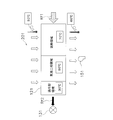
- FIG. 2 is a block diagram showing a control system of the air conditioner.
- the air conditioning apparatus 1 is a multi-room air conditioning apparatus, and indoor units 11, 12, 13, 14 as a plurality of use side units are connected in parallel to an outdoor unit 19 as a single heat source side unit.
- the outdoor unit 19 includes a compressor 36, an accumulator 37, a four-way switching valve 38, an outdoor heat exchanger 35 that is a heat source heat exchanger, expansion valves 31, 32, 33, 34, and an outdoor fan 39 that is a heat source fan.
- the indoor units 11, 12, 13, 14 accommodate the indoor heat exchangers 21, 22, 23, 24, which are use side heat exchangers, and the indoor fans 51, 52, 53, 54 which are use side fans.
- the compressor 36 is configured to be able to control the number of revolutions by a control unit 40 described later.
- the compressor 36 is a device that compresses the low-pressure refrigerant of the refrigeration cycle to a high pressure.
- the compressor 36 is a displacement compressor that is rotationally driven by a compressor motor 36a whose frequency can be controlled by an inverter.
- the outdoor fan 39 is driven by an outdoor fan motor 39a whose rotation number can be controlled by the control unit 40.
- the outdoor fan 39 is, for example, a propeller fan, and is configured to be able to change the air volume by changing the rotational speed.
- the expansion valves 31 to 34 are controlled by the control unit 40 so that the respective valve openings are individually changed.
- the indoor fans 51, 52, 53, 54 are driven by the indoor fan motors 51a, 52a, 53a, 54a that can control the number of rotations by the control unit 40.
- the indoor fans 51 to 54 are, for example, centrifugal fans or multi-blade fans, and are configured to be able to change the air volume by changing the rotational speed.
- the refrigerant circuit 2 of the air conditioner 1 is configured by connecting a compressor 36, an accumulator 37, a four-way switching valve 38, an outdoor heat exchanger 35, expansion valves 31 to 34, and indoor heat exchangers 21 to 24. .
- the refrigerant flowing through the refrigerant path r1 flows through the compressor 36, the indoor heat exchanger 21, the expansion valve 31, the outdoor heat exchanger 35, the four-way switching valve 38, and the accumulator 37.
- the refrigerant flowing through the refrigerant path r2 flows through the compressor 36, the indoor heat exchanger 22, the expansion valve 32, the outdoor heat exchanger 35, the four-way switching valve 38, and the accumulator 37.
- the refrigerant flowing through the refrigerant path r3 flows through the compressor 36, the indoor heat exchanger 23, the expansion valve 33, the outdoor heat exchanger 35, the four-way switching valve 38, and the accumulator 37.
- the refrigerant flowing through the refrigerant path r4 flows through the compressor 36, the indoor heat exchanger 24, the expansion valve 34, the outdoor heat exchanger 35, the four-way switching valve 38, and the accumulator 37.
- a vapor compression refrigeration cycle is performed on each of the refrigerant paths r1 to r4.
- R32 composition 100% of HFC-32 of a single refrigerant having a small global warming potential is used.
- the four-way switching valve 38 and the indoor heat exchangers 21 to 24 are connected by a gas refrigerant pipe 17, and the expansion valves 31 to 34 and the indoor heat exchangers 21 to 24 are liquid refrigerant pipes 18. Connected by
- the air conditioning apparatus 1 is equipped with many temperature sensors which consist of thermistors.
- the outdoor temperature sensor 97 detects the outside air temperature of the outdoor space where the outdoor unit 19 is installed.
- the discharge pipe temperature sensor 90 is attached to the discharge pipe of the compressor 36 and detects the discharge temperature To of the refrigerant discharged from the compressor 36.
- the outdoor heat exchange temperature sensor 95 which detects evaporation temperature at the time of heating operation is attached to the outdoor heat exchanger 35 which is a heat source side heat exchanger, and detects evaporation temperature Te at the time of heating operation.
- the indoor heat exchange temperature sensors 91, 92, 93, 94 are attached to the indoor heat exchangers 21, 22, 23, 24, and detect condensation temperatures Tc1 to Tc4 during heating operation.
- the liquid pipe temperature sensors 81, 82, 83, 84 are attached to the parts 18a, 18b, 18c, 18d of the liquid refrigerant pipe 18 which are branched from the outdoor heat exchanger 35 and extend to the indoor heat exchangers 21-24.
- the tube temperatures Tl1 to Tl4 are detected.
- the indoor temperature sensors 61 to 64 are disposed in the corresponding indoor units 11 to 14 so as to detect indoor temperatures Tr1 to Tr4 which are temperatures of indoor air taken into the indoor units 11 to 14, respectively.
- the gas pipe temperature sensors 71 to 74 are attached to portions 17a, 17b, 17c and 17d of the gas refrigerant pipe 17 which are branched from the four-way switching valve 38 and extend to the indoor heat exchangers 21 to 24.
- the control unit 40 controls the operation of the air conditioner 1 based on the detection values of these temperature sensors.
- the control unit 40 can be configured by a controller (automatic control device).
- the indoor air cooled by the evaporation of the refrigerant is blown out to the indoor space by the indoor fans 51 to 54 to cool the indoor space. Further, the refrigerant evaporated and vaporized in the indoor heat exchangers 21 to 24 returns to the outdoor unit 19 through the gas refrigerant pipe 17 and is sucked into the compressor 36 through the four-way switching valve 38 and the accumulator 37.
- the refrigerant returned to the outdoor unit 19 is decompressed by the expansion valves 31 to 34, and further exchanges heat with the outdoor air supplied by the outdoor fan 39 and the outdoor heat exchanger 35 to evaporate.
- the refrigerant evaporated and vaporized in the outdoor heat exchanger 35 is sucked into the compressor 36 through the four-way switching valve 38 and the accumulator 37.
- the indoor heat exchangers 21 to 24 function as a radiator of the refrigerant to warm the room
- the outdoor heat exchanger 35 heat source side heat exchanger It functions as a refrigerant evaporator.
- FIG. 2 shows an outline of a control system of the air conditioner 1.
- the control unit 40 includes indoor control devices 41 to 44 and an outdoor control device 45. Specifically, the control board (corresponding to the outdoor control device 45) in the electric component box (not shown) of the outdoor unit 19 and the control board in the electric component box (not shown) of the indoor units 11 to 14
- the control unit 40 is configured by being connected (corresponding to the indoor control devices 41 to 44).
- the indoor control devices 41 to 44 are configured to include CPUs 41a to 44a and memories 41b to 44b.
- the outdoor control device 45 is configured to include a CPU 45a, a memory 45b, and a timer 45c.
- the indoor units 11 to 14 are described in the memories 41 b to 45 b.
- the CPUs 41a to 45a execute the programs described in the memories 41b to 45b to generate signals for controlling the respective devices.
- the indoor units 11 to 14 are provided with a receiving unit that receives an instruction of the remote controller 111 to 114 operated by the user, a driver of a motor that changes the blowing direction of the conditioned air, and a display unit that displays an operation mode and the like. It is done.
- control unit 40 receives the detection values of the above-described temperature sensors, and controls the cooling operation and the heating operation based on these values.
- the control unit 40 controls the frequency of the compressor 36 and the opening degree of the expansion valves 31 to 34 during the cooling operation.
- the control in the cooling operation is the same as that in the related art, so the description is omitted here.
- the control unit 40 performs start control when starting the heating operation by starting the compressor 36 from the stopped state, and the expansion valves 31 to 34 in the normal heating operation state in which the refrigerant state after start is stable.
- Target discharge pipe temperature control and sub-cool control for adjusting the valve opening degree, capacity control of the compressor 36 in the normal heating operation state, control when there is a demand for high temperature wind, frost that has reached the outdoor heat exchanger 35 Defrost control for melting is performed.
- target discharge pipe temperature control during normal heating operation, subcool control and capacity control, and high-temperature air control when there is a demand for high-temperature air which are related to the technology of the present disclosure, will be described.
- Target discharge pipe temperature control in normal heating operation In target discharge pipe temperature control, the compressor is indirectly controlled by controlling the opening degree of the expansion valves 31 to 34 using the discharge pipe temperature. While performing superheat degree control on the suction side of 36, the control of the discharge temperature of the compressor 36 and the operation of the compressor 36 can be managed even if the refrigerant sucked by the compressor 36 becomes wet. Even if the refrigerant sucked into the compressor 36 becomes wet, the discharge pipe temperature control is performed within the range in which the compressor 36 is not damaged.
- the control unit 40 sets the valve opening degree of the expansion valves 31 to 34 so that the discharge temperature To detected by the discharge pipe temperature sensor 90 approaches the target discharge pipe temperature Tm. adjust.
- the temperature detected by the discharge pipe temperature sensor 90 is the temperature of the discharge pipe of the compressor 36, not the temperature of the refrigerant to be discharged. Therefore, it may be preferable to correct the temperature detected by the discharge pipe temperature sensor 90, but here, the temperature detected by the discharge pipe temperature sensor 90 will be described as being equal to the temperature of the refrigerant to be discharged.
- the control unit 40 controls the target discharge pipe temperature Tm based on the evaporation temperature Te detected using the outdoor heat exchange temperature sensor 95 and the condensation temperature Tc detected using the indoor heat exchange temperature sensors 91 to 94. It is set.
- the target discharge pipe temperature Tm has a value such that the degree of discharge superheat described later is maintained at 10 ° C. or more in the normal operation state.
- the refrigerant is drawn into the compressor 36 and discharged from the compressor 36 at a point (pressure and temperature) at which the efficiency of the refrigeration cycle is high. While the valve opening degree of the expansion valves 31 to 34 as a whole is adjusted by the target discharge pipe temperature control, the valve opening degree of each of the expansion valves 31 to 34 is adjusted according to the heating capacity required for each indoor unit 11 to 14 Adjusted.
- the capacity control of the compressor 36 during normal heating operation is performed by increasing or decreasing the rotational speed of the compressor 36 based on requests from the indoor units 11 to 14 Control. Specifically, based on the difference between the indoor temperatures Tr1 to Tr4 detected by the indoor temperature sensors 61 to 64 of the indoor units 11 to 14 and the set temperatures Ts1 to Ts4 set by the remote controllers 111 to 114, the control unit 40 However, the required output of the compressor 36 is determined, and the number of revolutions of the compressor 36 is changed.
- Subcool control in normal heating operation state is the valve opening degree of each of the expansion valves 31 to 34 determined by the target discharge pipe temperature control. It is control which corrects so that distribution may be performed appropriately.
- the control unit 40 uses the fluid tube temperatures Tl1 to Tl4 detected by the fluid tube temperature sensors 81 to 84 in the driver's room and the condensation temperatures Tc1 to Tc4 detected by the indoor heat exchange temperature sensors 91 to 94.
- the degree of cooling SC1 to SC4 can be calculated.
- the indoor units 11 to 14 are described as being disposed in different first to fourth rooms.
- the driver's room means a room among the first room to the fourth room in which the indoor units 11 to 14 are on.
- the room in which the indoor units 11 to 14 are thermo-off is called a stop room.
- the control unit 40 sets the target using, for example, the rotational speed fc of the compressor 36 and the temperature difference between the discharge temperature To and the target discharge pipe temperature Tm.
- the degree of supercooling SCm is calculated. For example, when the indoor unit 11 in the first room is thermo-on, the target subcooling degree SCm is compared with the subcooling degree SC1 of the indoor unit 11 in the first room, which is the driving room, of the expansion valve 31 Correct the valve opening.
- the valve opening degree of the expansion valve 31 of the first room is increased.
- the valve opening degree of the expansion valve 31 of the first room is reduced.
- the degree of opening of the expansion valve 31 of the first room is maintained as it is.
- control is performed so as not to change the valve opening degree when the difference ⁇ SC between the subcooling degree SC1 and the target subcooling degree SCm is within a predetermined range. It is also good.
- High-temperature wind control is started, for example, by the user operating a high-temperature wind request operation button provided on the remote controllers 111 to 114 that requires high-temperature wind.
- the high temperature wind control is a hot air blown out through the first user-side heat exchanger of the room in which the indoor unit receiving the high temperature wind request is installed when the high temperature wind request is received. It is control which raises temperature temporarily.
- a room in which an indoor unit having a request for high-temperature wind is installed may be referred to as a high-temperature wind room, and a room in which an indoor unit having no request for high-temperature wind is installed may be referred to as another room. .
- the fourth room is the high temperature air room
- the indoor heat exchanger 24 of the fourth room is the first use side. It corresponds to a heat exchanger.
- the high temperature wind operation button is operated by a plurality of remote controllers 111 to 114
- the plurality of rooms become high temperature wind rooms
- the indoor heat exchangers of the plurality of high temperature wind rooms are the first use side heat It can also be configured to correspond to a switch.
- the control unit 40 since it may not be appropriate to perform high temperature wind control even if there is a request, the control unit 40 satisfies the other start conditions as one start condition that the high temperature wind request operation button is pressed.
- the high temperature air control may be started by a method other than the method of operating the high temperature air request operation button of the remote controller 111-114.
- the high temperature air control is started when the user operates the high temperature air request operation button of the remote controller 111-114.
- the indoor heat exchanger of the room in which the high-temperature wind request operation button is pressed is referred to as a first use-side heat exchanger.
- a path to which the first usage-side heat exchanger is connected is referred to as a first refrigerant path
- an expansion valve present in the first refrigerant path is referred to as a first expansion valve.
- the refrigerant path r4 is the first refrigerant path
- the expansion valve 34 is the first expansion valve.
- the control unit 40 counts, by the timer 45c, an elapsed time after entering the high temperature air control, and cancels the high temperature air control on the condition that the time set in advance (for example, 30 minutes) is reached.
- the control unit 40 cancels the high temperature wind control. For example, when the indoor unit 14 in the high-temperature room is turned off by an instruction from the remote controller 114, etc., the indoor unit which has issued the request for high-temperature air disappears. In such a case, the timer 45c is used. Even if the count does not reach the set time, the hot air control is released.
- the control unit 40 performs control to increase the flow rate of the refrigerant flowing to the first usage-side heat exchanger when the high-temperature wind request is received. Specifically, the control unit 40 increases the rotational speed of the compressor 36 when receiving the high temperature wind request. For example, the control unit 40 adds a correction value to the number of revolutions of the compressor 36 to make the number of revolutions of the compressor 36 larger than that before the high temperature wind request. Further, in order to increase the rotational speed of the compressor 36 when receiving a high temperature wind request, for example, the control unit 40 may be configured to raise the upper limit value of the rotational speed of the compressor 36.
- the control part 40 performs control which increases the flow volume of the external air which flows into a heat-source side heat exchanger, when high temperature wind request
- the control unit 40 restricts the volume of air blown out as hot air by passing through the first usage-side heat exchanger that has received a demand for high-temperature air. Take control.
- the first usage-side fan blows air to the first usage-side heat exchanger in the high-temperature air room.
- the control unit 40 sets the fan tap of the indoor fan 52 that has become the first use side fan to a preset tap or less Restrict to the air volume tap.
- the indoor fan 52 for example, when switching in six steps is possible, the air volume is limited to the third or less from the smallest.
- the control unit 40 controls so as to gradually decrease.
- the control unit 40 is configured to increase the temperature of the refrigerant flowing through the first usage-side heat exchanger in the high-temperature air room when the demand for the high-temperature air is received. Change the control of the expansion valve. In other words, the control unit 40 changes the valve opening degree of the first expansion valve so as to raise the average temperature of the first usage-side heat exchanger. Specifically, before high-temperature air control, the superheated region formed by the gas refrigerant Rf1 flowing into the first usage-side heat exchanger 121 as shown in FIG. 3A is subjected to high-temperature air control as shown in FIG. 3B. Make larger as shown in. Accordingly, the large subcooling area as shown in FIG.
- the first use side heat exchanger 121 raises the room temperature of 20 ° C. to 50 ° C. by heat exchange before the high temperature wind control, the first use after the high temperature wind control
- the side heat exchanger 121 can raise the room temperature of 20 ° C. to 60 ° C. by heat exchange.
- the second usage-side heat exchanger 122 of the second usage unit 202 which did not have a request for high-temperature wind in the driver's cab, as shown in FIG. 3C, has a supercooling region after high-temperature wind control.
- the temperature of the hot air blown out from the second usage-side heat exchanger 122 tends to decrease because the temperature tends to increase and the overheat area tends to decrease.
- the second usage-side heat exchanger 122 of the second usage unit 202 which did not have a request for high-temperature wind in the stop room is stopped by the second usage-side fan, as shown in FIG. 3D. After control, the supercooling area is further increased and the overheating area is further reduced.
- the refrigerant flowing out of the subcooling region is the liquid refrigerant Rf2. It is also shown that the average temperature of the refrigerant in the superheated region is 70 ° C., the temperature of the refrigerant in the gas-liquid two-phase region is 50 ° C., and the temperature of the refrigerant in the subcooling region is 30 ° C. It is a model for explanation, and the actual case does not necessarily agree with this model. Further, in FIGS. 3A, 3 B and 3 C, the first expansion valve 131 expands the liquid refrigerant Rf 2 that has flowed out of the first use side heat exchanger 121, and blows the first use side heat exchanger 121.
- the first use side fan 151, and the second expansion valve 132 expands the liquid refrigerant Rf2 that has come out of the second use side heat exchanger 122, and blows the second use side heat exchanger 122. Is the second user side fan 152.
- the control unit 40 performs the first user-side heat exchange shown in FIGS. 3A and 3B.
- the target subcooling degree SCm is lowered with respect to the first usage-side unit 201 having the first usage-side heat exchanger 121, Control is performed to increase the superheated area occupied by the gas refrigerant in the first usage-side heat exchanger 121.
- the control unit 40 calculates a target degree of supercooling SCmH for high-temperature air control by subtracting a preset predetermined value.
- the predetermined value may be a constant, a value calculated according to a predetermined calculation formula, or a value described in a table in the memories 41b to 45b. For example, assuming that the target degree of supercooling SCm during normal heating operation is 12 degrees, four indoor units 11 to 14 are connected as shown in FIG. If there is a request for the high temperature wind, the target degree of supercooling SCmH after the change of the indoor unit in the high temperature room is changed to 5 degrees.
- the target degree of supercooling SCmH should be increased in order to perform efficient operation as a whole while considering the effects on other rooms. Is preferred. For example, when there are two high temperature air rooms (when there is a request for high temperature air from two indoor units), there is only one high temperature room (for one high temperature air from only one indoor unit) However, for example, if there are two high temperature air rooms, the target degree of supercooling SCmH is 7 to 8 degrees for both rooms and 9 if there are three high temperature air rooms. And so on. That is, in the case where there is a demand for high-temperature air from a plurality of indoor units, it is preferable that the reduction range of the target degree of supercooling SCmH be made smaller as the number of requested indoor units increases.
- the control part 40 retains the target supercooling degree SCm of the indoor unit for which there was no request for high-temperature air in the case of normal heating operation. It is configured to perform control to maintain. However, in order to further concentrate the capability in the high temperature air room, the control unit 40 may be configured to perform control to increase the target degree of subcooling of the room where there was no request for high temperature air.
- the target supercooling degree SCm is 12 degrees just before entering the high temperature wind control
- the high temperature After entering the wind control the target degree of supercooling SCmH of the indoor unit 11 is set to 5 degrees
- the degree of target supercooling SCmH of the indoor units 12 to 14 is set to 13 degrees.
- the control unit 40 performs target discharge pipe temperature control without performing subcool control.
- the valve opening degree of the expansion valve corresponding to the stop room changes in the direction of decreasing.
- the increase in the degree of valve opening of the expansion valve causes the indoor heat exchanger in the stop room to have a demand for high temperature wind.
- the amount of liquid refrigerant which is reduced by the use-side heat exchanger 121 (see FIG. 3B) is accumulated. As a result, the distribution of the refrigerant as a whole of the air conditioning apparatus 1 is optimized, and the efficient heating operation can be continued.
- a reservoir for storing the refrigerant expelled from the first usage-side heat exchanger 121 may be provided in the refrigerant circuit 2, as described above, the excess refrigerant is stored in the indoor heat exchanger in the stop room The addition of equipment can be omitted.
- the indoor heat exchange temperature sensors 91 to 94 attached to the indoor heat exchangers 21 to 24 function as intermediate temperature sensors disposed between the refrigerant outlet and the refrigerant inlet of the indoor heat exchangers 21 to 24.
- the control unit 40 controls the indoor heat exchange temperature sensor when the indoor unit 11 is thermo-on
- the control shifts to the protection control, but when the thermo-off, the control shifts to the protection control.
- the indoor heat exchange temperature sensor 91 is a liquid refrigerant.
- the possibility of detecting the temperature is high.
- the indoor heat exchange temperature sensor 91 detects excessive cooling, no protection control is performed, so that a large amount of refrigerant is accumulated in the indoor unit 11 which does not have a request for high-temperature air and is thermo-off. Can.
- thermo-off of indoor units that have required high-temperature wind A large amount of heat is supplied to the room air of the high-temperature wind room where the indoor units that have required high-temperature wind are installed . Therefore, the user often exceeds the set temperature. Therefore, if the heating operation is managed with the target set temperature set by the user as the target, the indoor unit frequently repeats the thermo-on and the thermo-off to impair the user's comfort.
- the control unit 40 automatically changes the set temperature of the indoor unit from which the high temperature air is blown to the maximum value so as not to repeat the heat on and the heat off. The changed set temperature is returned to the user's setting by the control unit 40 at the end of the high temperature wind control.
- the indoor unit 13 is the first usage-side unit for which high-temperature wind is required, and the other indoor units 11, 12, Assuming that No. 14 is a second usage-side unit where there is no request for high-temperature air, the control unit 40 makes it easy to perform the thermo-off operation of the heating operation using the refrigerant paths r1, r2, and r4, which are the second refrigerant paths. , The thermo-off conditions of the indoor units 11, 12 and 14 are changed.
- Tr2-Ts2 the difference between the set temperatures Ts1, Ts2, and Ts4 and the room temperatures Tr1, Tr2, and Tr4 from the indoor units 11, 12, and 14 in the other rooms.
- Tr4-Ts4 Tr4-Ts4
- the control unit 40 makes a change to loosen the thermo-off condition.
- the change of the thermo-off condition does not necessarily have to be the same, and the indoor unit 11 may be different such that the difference ⁇ Td1 is 0 degrees, and the indoor unit 12 may be different such as the difference ⁇ Td2 is 1 degree.
- the second usage side A transition is made to a high temperature wind mode in which control is performed so that the air volume of the indoor fans 51, 52, 54 which are fans is reduced or eliminated.
- the control unit 40 determines the air volume of the indoor fans 51, 52, 54. Decrease gradually.
- a pressure sensor may be used as the indoor heat exchange temperature sensors 91 to 94, and the high-pressure refrigerant pressure detected by the pressure sensor may be converted to a pressure equivalent saturation temperature. If the indoor heat exchange temperature sensors 91 to 94 are temperature sensors such as thermistors, the degree of subcooling may not be detected properly. As described above, the accuracy of control can be improved by replacing the pressure value of the high pressure refrigerant with the high pressure saturation temperature.
- step S1 when the high temperature air operation button of the remote controller 113 is operated and a request for high temperature air is transmitted from the indoor unit 13 to the control unit 40, high temperature air control is started (step S1).
- the control unit 40 starts counting by the timer 45c (step S2).
- step S3 the control unit 40 gradually reduces the number of rotations of the indoor fan 53 of the indoor unit 13 in the high-temperature room (step S3).
- the control unit 40 for example, reduces the rotational speed of the indoor fan 53 at a rate of 100 to 200 rpm per minute.
- step S4 it is determined whether or not to turn off the heat based on whether or not the temperature is not the same as the set temperatures Ts1, Ts2 and Ts4 after the change of the heat-off condition although the heat-off is not performed. For example, if the indoor temperature Tr4 has reached the set temperature Ts4, the indoor unit 14 is thermo-offed (step S5). Note that step S3 may be performed in parallel with steps S4 and S5, or step S3 may be performed after steps S4 and S5 are performed first.
- Control unit 40 determines whether the high-pressure equivalent saturation temperature (condensing temperature Tc (for example, condensing temperature Tc1)) is equal to or higher than a constant temperature Tp1 (step S5). If the high-pressure equivalent saturation temperature is less than the constant temperature Tp1, the control unit 40 reduces the rotational speed of the indoor fans 51 and 54 by 40 rpm (step S7). Tp1 in this case is, for example, forty and several degrees.
- step S8 is performed after step S7, the determination of step S6 may be performed again after step S7.
- step S8 If the high-pressure equivalent saturation temperature becomes Tp1 or higher, a request to turn off the high-temperature air control function comes (step S8), and the timer 45c does not count up (step S9). In order to continue, the process returns to step S4 to repeat the above operation. If a request for turning off the high temperature air control function is received (step S8), or the timer 45c counts up (step S9), the high temperature air mode is ended.
- the outdoor unit 19 is provided with four pairs of connection ports for liquid and gas pipes to which the four indoor units 11 to 14 can be connected, and two to four indoor units can be connected to the outdoor unit 19
- the technology of the present disclosure is applied to the multi-room air conditioner 1.
- the number of connectable indoor units may be plural, and up to five indoor units can be connected to one outdoor unit.
- the technology of the present disclosure can also be applied to various air conditioners.
- the technology of the present disclosure can also be applied to an air conditioner in which up to three indoor units can be connected to one outdoor unit.
- the technology of the present disclosure may be applied to a pair type air conditioner in which one indoor unit is connected to one outdoor unit.
- step S6 it is determined whether the high pressure equivalent saturation temperature is in the drooping zone, no change zone, or up zone in FIG. If it is in the hanging zone, the control unit 40 makes the determination of step S8 after lowering the upper limit fan tap of the indoor fan 52, 52 by one tap in step S7. When it is in the no change zone, the determination in step S8 is performed as it is. When in the up zone, the upper limit fan tap is raised by one tap and then the determination in step S8 is performed.
- the flow rate of the first use side heat exchanger is changed by changing the target degree of supercooling SCm of the indoor unit in the high-temperature air room in the subcool control.
- the control of the first expansion valve was changed so that the temperature of the refrigerant rises
- the temperature of the refrigerant flowing through the utilization side heat exchanger is corrected by correcting the opening degree of the first expansion valve of the indoor unit in the high temperature air room It may be configured to go up.
- the valve opening degree of the first expansion valve of the indoor unit in the high temperature air room may be fixed at a predetermined valve opening degree.
- the control of the first expansion valve which is performed so that the temperature of the refrigerant flowing through the first usage-side heat exchanger rises, is not limited to the change of the target degree of supercooling SCm.
- control unit 40 performs control by interpreting and executing the executable program and data stored in the memory by the CPU.
- the program and data may be introduced into the memory via the recording medium or may be executed directly from the recording medium. Further, the program and data may be introduced from the recording medium to the memory through a telephone line, a transport path, or the like.
- the control unit 40 may be configured using an integrated circuit (IC) capable of performing control similar to that performed using the CPU and the memory. Examples of the IC here include a large-scale integrated circuit (LSI), an application-specific integrated circuit (ASIC), a gate array, a field programmable gate array (FPGA), and the like.
- LSI large-scale integrated circuit
- ASIC application-specific integrated circuit
- FPGA field programmable gate array
- the control unit 40 changes the control of the expansion valve 31 to raise the temperature of the refrigerant flowing through the indoor heat exchanger 21 and, as shown in, for example, FIG.
- the average temperature of the refrigerant flowing to the indoor heat exchanger 21 (average temperature of the indoor heat exchanger) is raised.
- the overheating area of the indoor heat exchanger 21 is increased.
- the control unit 40 controls the refrigerant paths r2 to r4 for which there is no request for high temperature air (a second The thermooff conditions of the indoor units 12 to 14 in the refrigerant paths r2 to r4 are changed so that the indoor units 12 to 14 connected to the example of the path) can be easily turned off. Since the indoor unit 12 is in the thermo-on state and the indoor units 13, 14 are in the thermo-off state, only the indoor unit 12 may change the thermo-off condition. However, if the indoor units 13 and 14 are thermo-off in the heating operation state, it is expected that the thermo-off will occur if the indoor temperatures Tr3 and Tr4 decrease.
- thermo-off conditions of the indoor units 13 and 14 in the thermo-off state are changed to facilitate the thermo-off, the thermo-off can be made in a short time when the thermo-on is performed later.
- the overcooling region decreases in the indoor heat exchanger 21 of the refrigerant path r1 and overheating occurs. Even if the region increases, the refrigerant of the air conditioner 1 can be properly distributed, and the air conditioner 1 can maintain an efficient operating state.
- the remote controllers 111 to 114 can transmit the high temperature wind request and the control unit 40 can receive the high temperature wind request.
- the controller 111-114 can be used to instruct the user to perform hot air control as needed.
- the control unit 40 automatically changes the set temperature Ts1 of the indoor unit 11 installed in the air conditioning target chamber into which the warm air from the indoor heat exchanger 21 is blown out to the maximum value. Therefore, the indoor temperature Tr1 of the space to be air-conditioned tends to rise by raising the temperature of the warm air in response to the request for high temperature air, but the refrigerant path r1 is used compared to the case where the set temperature Ts1 is not changed. It is possible to make it difficult for the heating operation of the indoor unit 11 in the high temperature room to be thermo-off. As a result, it is possible to secure comfort by suppressing an increase in the number of times the warm air from the indoor heat exchanger 21 stops due to the request for the high temperature wind.
- the control unit 40 uses the fact that the heating operation of the indoor units 13 and 14 using the refrigerant paths r3 and r4 for which there is no request for high-temperature air is thermo-off to use the second
- the expansion valves 33, 34 which are the second expansion valves, are controlled so as to store the refrigerant in the indoor heat exchangers 23, 24, which are the side heat exchangers.
- the surplus refrigerant generated to raise the temperature of the refrigerant flowing through the indoor heat exchanger 21 can be properly distributed, and the temperature of the refrigerant drawn into the compressor 36 can be easily controlled to be an efficient temperature. .
- the control unit 40 performs the control of the expansion valves 33 and 34 by the target discharge pipe control as a specific example of the description of the above (6-10), thereby the second refrigerant path
- the expansion valve 33 is provided so that the temperature of the refrigerant sucked into the compressor 36 or the temperature of the refrigerant discharged from the compressor 36 approaches the target temperature when the heating operation using a certain refrigerant path r3, r4 is thermo-off It controls the valve opening of 34.
- Such control allows the refrigerant to be stored in the indoor heat exchangers 23, 24, as described with reference to FIG. 3D.
- control unit 40 generates the indoor heat exchange temperature sensor 93, which is an intermediate temperature sensor, when the heating operation using the refrigerant paths r3 and r4, which are the second refrigerant paths, is thermo-off.
- the system is configured not to shift to protection control even if the refrigerant is detected to be in the overcooling state by 94, while storing the liquid refrigerant even if the indoor heat exchange temperature sensors 93 and 94 detect the overcooling state Since the heating operation can be continued, a large amount of liquid refrigerant can be stored in the indoor heat exchangers 23 and 24 which are the second use side heat exchangers in which the heating operation is thermo-off, which is the first use side heat exchanger It becomes easy to expand the overheated area which the gas refrigerant of indoor heat exchanger 21 occupies.
Abstract
Description
本開示の一実施形態に係る空気調和装置の冷媒回路を、図1に示す。空気調和装置1は、多室型空気調和装置であって、1つの熱源側ユニットである室外機19に対して、複数の利用側ユニットである室内機11,12,13,14が並列に接続される構成である。室外機19は、圧縮機36、アキュムレータ37、四路切換弁38、熱源側熱交換器である室外熱交換器35、膨張弁31,32,33,34、及び熱源側ファンである室外ファン39を収容している。室内機11,12,13,14は、利用側熱交換器である室内熱交換器21,22,23,24及び利用側ファンである室内ファン51,52,53,54を収容している。
(2-1)冷房時の冷媒の流れ
次に空気調和装置1の動作の概略を説明する。冷房運転時は、四路切換弁38が図1において実線で示す状態に保持される。圧縮機36から吐出された高温高圧のガス冷媒は、四路切換弁38を介して室外熱交換器35に流入し、室外ファン39により供給される外気と室外熱交換器35で熱交換して凝縮・液化する。液化した冷媒は、膨張弁31~34で減圧され、室内ファン51~54により供給される室内空気と室内熱交換器21~24でさらに熱交換して蒸発する。冷媒の蒸発によって冷却された室内空気は、室内ファン51~54によって室内空間へと吹き出され、室内空間を冷房する。また、室内熱交換器21~24で蒸発して気化した冷媒は、ガス冷媒配管17を通って室外機19に戻り、四路切換弁38及びアキュムレータ37を経て圧縮機36に吸い込まれる。
暖房運転時は、四路切換弁38が図1において破線で示す状態に保持される。圧縮機36から吐出された高温高圧のガス冷媒は、四路切換弁38を介して各室内機11~14の室内熱交換器21~24に流入し、室内ファン51~54により供給される室内空気と室内熱交換器21~24で熱交換して凝縮・液化する。冷媒の凝縮によって加熱された室内空気は、室内ファン51~54によって室内空間へと吹き出され、室内空間を暖房する。室内熱交換器21~24において液化した冷媒は、液冷媒配管18を通って室外機19に戻る。室外機19に戻った冷媒は、膨張弁31~34で減圧され、室外ファン39により供給される室外空気と室外熱交換器35でさらに熱交換して蒸発する。室外熱交換器35で蒸発して気化した冷媒は、四路切換弁38及びアキュムレータ37を経て圧縮機36に吸い込まれる。
(3-1)概要
図2には、空気調和装置1の制御系統の概要が示されている。制御部40は、室内制御装置41~44と室外制御装置45とを含んでいる。具体的には、室外機19の電装品ボックス(図示せず)の中の制御基板(室外制御装置45に対応)および室内機11~14の電装品ボックス(図示せず)の中の制御基板(室内制御装置41~44に対応)が接続されて制御部40が構成されている。室内制御装置41~44は、CPU41a~44a及びメモリ41b~44bを含んで構成されている。また、室外制御装置45は、CPU45a、メモリ45b及びタイマ45cを含んで構成されている。メモリ41b~45bには、室内機11~14及び室外機19を制御するためのプログラム及びデータが記述されている。CPU41a~45aは、メモリ41b~45bに記述されているプログラムを実行することにより、各機器を制御するための信号を生成する。さらに、室内機11~14には、ユーザが操作入力するリモートコントローラ111~114の指令を受け付ける受信部、空調空気の吹出方向を変えるモータのドライバ、及び運転モードなどを表示する表示部などが設けられている。
制御部40は、冷房運転中の圧縮機36の周波数や膨張弁31~34の弁開度を制御する。冷房運転における制御については、従来通りであるため、ここでは説明を省略する。
制御部40は、停止状態から圧縮機36を起動して暖房運転を始めるときの起動制御、起動後の冷媒状態が安定した通常暖房運転状態における膨張弁31~34の弁開度調整のための目標吐出管温度制御及びサブククール制御、通常暖房運転状態における圧縮機36の容量制御、高温風要求があった場合の制御、室外熱交換器35に着いた霜を溶かすための除霜制御などを行う。ここでは、本開示の技術と関連する通常暖房運転時の目標吐出管温度制御、サブクール制御及び容量制御並びに高温風要求があった場合の高温風制御について説明する。
目標吐出管温度制御においては、吐出管温度を用いて膨張弁31~34の弁開度を制御することにより、間接的に圧縮機36の吸入側の過熱度制御を行うとともに、圧縮機36の吐出温度の管理及び圧縮機36が吸入する冷媒が湿り状態になっても圧縮機36の運転が管理できるように構成されている。圧縮機36に吸入される冷媒が湿り状態になっても、圧縮機36が損傷しない範囲で吐出管温度制御が行われる。
通常暖房運転状態における圧縮機36の容量制御は、各室内機11~14からの要求に基づいて圧縮機36の回転数を上下させる制御である。具体的には、室内機11~14の室内温度センサ61~64が検知する室内温度Tr1~Tr4と、リモートコントローラ111~114で設定された設定温度Ts1~Ts4との差に基づき、制御部40が、必要な圧縮機36の出力を決めて、圧縮機36の回転数を変更する。
通常暖房運転状態におけるサブクール制御は、目標吐出管温度制御により決定される各膨張弁31~34の弁開度を、暖房運転時の冷媒の分配が適正に行われるように補正する制御である。制御部40は、運転部屋の液管温度センサ81~84が検出する液管温度Tl1~Tl4と室内熱交温度センサ91~94が検出する凝縮温度Tc1~Tc4とを使って各運転部屋の過冷却度SC1~SC4を算出することができる。例えば、(SC1=Tc1-Tl1)などのように、各凝縮温度Tc1~Tc4から各液管温度Tl1~Tl4を差し引くことで、各運転部屋の過冷却度SC1~SC4を求めることができる。この実施形態では、室内機11~14が異なる第1部屋から第4部屋に配置されているとして説明する。ここで、運転部屋とは、第1部屋から第4部屋のうち室内機11~14がサーモオンしている部屋をいう。それに対して、第1部屋から第4部屋のうち室内機11~14がサーモオフしている部屋は停止部屋と呼ぶ。
高温風制御は、例えば、リモートコントローラ111~114に設けられている、高温風を要求する高温風要求操作ボタンをユーザが操作することにより開始される。ここで、高温風制御は、高温風の要求を受けた場合に、高温風要求を受けた室内機が設置されている部屋の第1利用側熱交換器を通過して吹出される温風の温度を一時的に上昇させる制御である。なお、以下の説明では、高温風の要求のあった室内機が設置されている部屋を高温風部屋、高温風の要求の無かった室内機が設置されている部屋を他室と呼ぶ場合もある。
制御部40は、高温風要求を受けた場合に、第1利用側熱交換器に流れる冷媒の流量を増やす制御を行う。具体的には、制御部40は、高温風要求を受けた場合に、圧縮機36の回転数を上げる。制御部40は、例えば、圧縮機36の回転数に補正値を加えて圧縮機36の回転数を高温風要求前に比べて大きくする。また、高温風要求を受けた場合に圧縮機36の回転数を上げるために、制御部40は、例えば、圧縮機36の回転数の上限値を引き上げるように構成されてもよい。
制御部40は、高温風要求を受けた第1利用側熱交換器を通過して温風として吹き出される風量を制限する制御を行う。ここでは、高温風部屋の第1利用側熱交換器には第1利用側ファンで送風する。具体的には、例えば、リモートコントローラ112の高温風要求操作ボタンが操作された場合には、制御部40は、第1利用側ファンとなった室内ファン52のファンタップを予め設定されたタップ以下の風量のタップに制限する。室内ファン52について、例えば、6段階の切換えが可能な場合に、風量が小さい方から3番目以下に制限するなどである。風量があまり小さくなり過ぎても高温風を受けている実感をユーザが得難い場合もあるので、温風の温度が下がり過ぎない適当な風量に設定される。また、風量を下げる場合には、制御部40は、徐々に下げるように制御する。
制御部40は、高温風の要求を受けた場合に、高温風部屋の第1利用側熱交換器を流れる冷媒の温度が上がるように第1膨張弁の制御を変更する。言い換えると、制御部40は、第1利用側熱交換器の平均温度を上げるように第1膨張弁の弁開度を変更する。具体的には、高温風制御前は、図3Aに示されているような第1利用側熱交換器121に流れ込んだガス冷媒Rf1によって形成される過熱領域を、高温風制御後は、図3Bに示されているように大きくする。それに伴って、高温風制御前は、図3Aに示されているよう大きかった過冷却領域が、高温風制御後は、図3Bに示されている過冷却領域のように小さくなる。その結果、例えば、高温風制御前に、第1利用側熱交換器121が20℃の室内温度を熱交換によって50℃まで上昇させていたのに比べて、高温風制御後は、第1利用側熱交換器121が20℃の室内温度を熱交換によって60℃まで上昇させることができるようになる。それに対して、運転部屋の高温風の要求の無かった第2利用ユニット202の第2利用側熱交換器122は、図3Cに示されているように、高温風制御後は、過冷却領域が増えて過熱領域が減る傾向にあり、第2利用側熱交換器122から吹き出される温風の温度は下がり気味になる。また、停止部屋の高温風の要求の無かった第2利用ユニット202の第2利用側熱交換器122は、図3Dに示されているように、第2利用側ファンが停止して、高温風制御後は、過冷却領域がさらに増えて過熱領域がさらに減る。
(4-3-1-1)運転部屋の目標過冷却度の変更
制御部40は、図3A及び図3Bに示されている第1利用側熱交換器121を有する第1利用側ユニット201が高温風の要求を受けた場合に、第1利用側熱交換器121を有する第1利用側ユニット201に対して、目標過冷却度SCmを下げて、第1利用側熱交換器121においてガス冷媒が占有する過熱領域を増やす制御を行う。例えば、制御部40は、通常暖房運転時と同様に目標過冷却度SCmを算出した後に、予め設定されている所定値を差し引いて高温風制御用の目標過冷却度SCmHを算出する。所定値は、定数であってもよく、また予め定められている計算式に従って計算される値であってもよく、メモリ41b~45b内のテーブルに記載されている値であってもよい。例えば、通常暖房運転時の目標過冷却度SCmが12度であるとすると、図1に示されているように4台の室内機11~14が接続され、そのうちの1台から高温風の要求があった場合には、その高温風の要求があった高温風部屋の室内機の変更後の目標過冷却度SCmHは5度に変更される。高温風の要求があった高温風部屋が2以上である場合は、他室への影響を考慮するとともに全体的に効率の良い運転をするために、目標過冷却度SCmHを大きくしていくことが好ましい。例えば、高温風部屋が2つである場合(2台の室内機から高温風の要求があった場合)は、高温風部屋が1つである場合(1台の室内機のみから高温風の要求があった場合)には5度であるのに対して例えば高温風部屋が2つの場合には目標過冷却度SCmHを両部屋とも7~8度に、高温風部屋が3つの場合には9~11度にするなどである。つまり、高温風の要求が複数の室内機からある場合には、要求がある室内機の数が多くなるほど目標過冷却度SCmHの下げ幅を小さくするように構成されることが好ましい。
制御部40は、ここでは、高温風の要求が無かった室内機の目標過冷却度SCmを通常暖房運転の場合のまま維持する制御を行うように構成されている。しかし、さらに高温風部屋に能力を集中させるために、制御部40は高温風の要求が無かった部屋の目標過冷却度を大きくする制御を行うように構成されてもよい。例えば、室内機11から高温風の要求があり、室内機12~14からは要求が無かった場合には、高温風制御に入る直前で目標過冷却度SCmが12度であったものが、高温風制御に入った後は室内機11の目標過冷却度SCmHを5度、室内機12~14の目標過冷却度SCmHを13度にするなどである。
停止部屋の室内機に対して、制御部40は、サブクール制御を行わずに目標吐出管温度制御を行う。この目標吐出管温度制御によって、停止部屋に対応する膨張弁の弁開度が小さくなる方向に変化する。このとき、停止部屋の室内ファンが停止しているが、膨張弁の弁開度が小さくなることによって、停止部屋の室内熱交換器には、高温風の要求があった高温風部屋の第1利用側熱交換器121(図3B参照)で減少した分の液冷媒が溜まることになる。その結果、空気調和装置1の全体としての冷媒の分配が適正化され、効率の良い暖房運転を続けることができる。例えば、第1利用側熱交換器121から追い出された冷媒を溜めるリザーバを冷媒回路2に設けてもよいが、上述のように停止部屋の室内熱交換器に余剰冷媒を溜めることでリザーバなどの機器の追加を省くことができる。
高温風の要求のあった室内機が設置されている高温風部屋の室内空気には、多くの熱量が供給される。そのため、ユーザが設定されている設定温度を超える場合が頻出する。従って、ユーザが設定した設定温度を目標に暖房運転を管理したのでは、室内機がサーモオンとサーモオフを頻繁に繰り返してしまってユーザの快適性を損ねることになる。このようにサーモオンとサーモオフを繰り返さないように、高温風の吹き出される室内機の設定温度を制御部40が自動的に最大値に変更する。この変更された設定温度は、高温風制御の終了とともに制御部40によりユーザの設定に戻される。
ここでは、室内機13が高温風の要求のあった第1利用側ユニットであり、他の室内機11,12,14は高温風の要求が無かった第2利用側ユニットであると仮定すると、第2冷媒経路である冷媒経路r1,r2、r4を用いた暖房運転がサーモオフし易くなるように、制御部40は、室内機11,12,14のサーモオフ条件を変更する。例えば、高温風制御に入るまでは、他室の室内機11,12,14が設定温度Ts1,Ts2,Ts4と室内温度Tr1,Tr2,Tr4との差ΔTd1(=Tr1-Ts1),ΔTd2(=Tr2-Ts2),ΔTd4(=Tr4-Ts4)が3度でサーモオフしていたものを、0度つまり設定温度Ts1,Ts2,Ts4と室内温度Tr1,Tr2,Tr4が等しい場合にサーモオフするように、制御部40がサーモオフ条件を緩める変更を行う。なお、サーモオフ条件の変更は、必ずしも同じである必要はなく、室内機11は差ΔTd1が0度、室内機12は差ΔTd2が1度のように異なるものとしてもよい。
高温風の要求のあった高温風部屋に設置されている室内機(第1利用側ユニット)の温風の温度が、高温風の要求の無かった他室の室内機(第2利用側ユニット)の風量に影響を受ける。また、高温風制御中に、第2利用側ユニットがサーモオンとサーモオフを繰り返すと、冷凍サイクルの高圧側の冷媒圧力が安定せず、第1利用側ユニットから吹き出される温風の温度がハンチングを起こす。
(5-1)変形例A
上記実施形態では、4台の室内機11~14を接続できる液管用およびガス管用の4対の接続ポートが室外機19に設けられ、室外機19に2台~4台の室内機を接続可能な多室型の空気調和装置1に本開示の技術を適用しているが、接続可能な室内機の台数は複数であればよく、最大で5台の室内機を1つの室外機に接続可能な空気調和装置に本開示の技術を適用することもできる。最大で3台の室内機を1つの室外機に接続可能な空気調和装置に対しても、本開示の技術を適用することができる。
上記実施形態では、冷房運転と暖房運転とを切り換えることができる空気調和装置1に本開示の技術を適用しているが、他の冷凍装置、例えば、暖房専用の空気調和装置などに本開示の技術を適用することも可能である。
上記実施形態では、図4を用いて説明したように、高温風モードに移行したときには、他室のファン回転数を下げる制御を行ったが、他室の運転部屋のファン風量が減るようにまたは無くなるように制御を行う高温風モードに移行したときに、他室の運転部屋の上限ファンタップを下げるように構成してもよい。実施形態の図4を用いて説明した場合のように、他室の運転部屋に室内機11,12が在るとすると、制御部40は、例えば室内熱交換器23の高圧相当飽和温度(凝縮温度Tc(凝縮温度Tc3))に基づいて室内ファン51,52の上限ファンタップを、例えば図5に示されているように変化させる。つまり、ステップS6では、高圧相当飽和温度が図5の垂下ゾーンにあるか、無変化ゾーンにあるか、またはアップゾーンにあるかが判断される。垂下ゾーンにある場合には、ステップS7において、制御部40が室内ファン52,52の上限ファンタップを1タップだけ垂下させた後にステップS8の判断を行う。無変化ゾーンにあるときには、そのままステップS8の判断を行う。アップゾーンにあるときは、上限ファンタップを1タップだけ上昇させた後にステップS8の判断を行う。
上記実施形態では、(4-3-1-1)で説明したように、サブクール制御において高温風部屋の室内機の目標過冷却度SCmを変更することにより、第1利用側熱交換器を流れる冷媒の温度が上がるように第1膨張弁の制御を変更したが、高温風部屋の室内機の第1膨張弁の弁開度を補正することによって1利用側熱交換器を流れる冷媒の温度が上がるように構成してもよい。例えば、高温風部屋の室内機の第1膨張弁の弁開度を予め設定されている一定の弁開度に固定するようにしてもよい。このように、第1利用側熱交換器を流れる冷媒の温度が上がるように行われる第1膨張弁の制御は、目標過冷却度SCmの変更に限られるものではない。
上記実施形態では、間接的に圧縮機36の吸入側の過熱度制御を行う目標吐出管温度制御を行う場合を例に挙げて説明したが、直接吸入側の過熱度制御を行う空気調和装置についても本開示の技術を適用することができる。
上記実施形態では、制御部40が、メモリに格納された実行可能なプログラム及びデータをCPUよって解釈実行することで制御を行う場合について説明した。このプログラム及びデータは、記録媒体を介してメモリ内に導入されてもよいし、記録媒体上から直接実行されてもよい。また、記録媒体からメモリへのプログラム及びデータの導入は、電話回線や搬送路等を介して行ってもよい。しかし、制御部40は、CPUとメモリを用いて行うのと同様の制御を行うことができる集積回路(IC)を用いて構成されてもよい。ここでいうICには、LSI(large-scale integrated circuit)、ASIC(application-specific integrated circuit)、ゲートアレイ、FPGA(field programmable gate array)等が含まれる。
以下の特徴の説明では、説明を分かり易くするために、室内機11がリモートコントローラ111から高温風の要求を受け、室内機12~14が高温風の要求を受けなかった場合を例に挙げる。また、高温風の要求を受けなかった室内機12~14のうち室内機12がサーモオンし、室内機13,14がサーモオフしているものとして以下の特徴の説明をする。
上述のように設定した例の状態に空気調和装置1があると、高温風部屋の室内機11の室内熱交換器21が第1利用側熱交換器になり、膨張弁31が第1膨張弁になる。制御部40は、高温風制御を行うときには、膨張弁31の制御を変更して、室内熱交換器21を流れる冷媒の温度を上げ、例えば図3Bに示されているように、過熱領域を広げることで室内熱交換器21に流れる冷媒の平均温度(室内熱交換器の平均温度)を上げている。その結果、室内熱交換器21で熱交換されて吹き出される温風に対して、通常の暖房運転よりも多くの熱量を与えることができ、高温風の要求を受けた室内機11から吹き出される温風の温度を十分に上げることができる。
上述のように設定した例では、高温風の要求を受けて制御部40が下げた室内機11の目標過冷却度SCmHにより、図3Bに示された第1利用側熱交換器121のように室内熱交換器21の過熱領域が増える。室内熱交換器21において高温のガス冷媒が占める過熱領域を増やすことができ、室内熱交換器21を通過する空気が受け取る熱量を増やして室内機11が吹出す温風の温度を十分に上げることができる。
上述のように設定した例では、上述の(4-3-3)で説明したように、制御部40により、高温風の要求の無かった冷媒経路r2~r4(高温風の無かった第2冷媒経路の例)に接続された室内機12~14がサーモオフし易くなるように冷媒経路r2~r4の室内機12~14のサーモオフ条件が変更される。室内機12がサーモオン状態にあり、室内機13,14がサーモオフ状態にあるので、室内機12のみサーモオフ条件を変更してもよい。しかし、室内機13,14が暖房運転されている状態でサーモオフされているのであれば、室内温度Tr3,Tr4が下がってくればいずれはサーモオフすることが予想される。そのため、サーモオフ状態にある室内機13,14のサーモオフ条件を変更してサーモオフし易くしておけば、後にサーモオンしたときに短期間でサーモオフさせることができることになる。このように、冷媒経路r2~r4を用いた暖房運転がサーモオフする期間が増えて冷媒経路r2~r4に冷媒が溜まり易くなると、冷媒経路r1の室内熱交換器21で過冷却領域が減って過熱領域が増えても空気調和装置1の冷媒を適切に配分でき、空気調和装置1は効率の良い運転状態を維持することができる。
上述のように設定した例では、高温風制御において圧縮機36の回転数を上げて室内熱交換器21に流れる冷媒の流量を増やすと、膨張弁31の制御が変更されて室内熱交換器21を流れる冷媒の温度が上がることともあいまってより多くの熱量が冷媒から室内熱交換器21を通過する空気に与えることができるようになる。
上述のように設定した例では、高温風制御において、熱源側ファンである室外ファン39の回転数を上げると熱源側熱交換器である室外熱交換器35での熱交換が促進されて蒸発能力が上がり、その結果、室内熱交換器21での凝縮能力が上がって室内熱交換器21を通過して吹き出される温風の温度を上げることができる。
上述のように設定した例では、高温風の要求を受けた場合に第1利用側ファンである室内ファン51の風量を所定値以下にすることで、風量が所定値を超える場合に比べて第1利用側熱交換器である室内熱交換器21を単位時間当たりに通過する空気の量が減少して単位体積の空気が受け取る熱量が増加する。
上記実施形態の構成では、リモートコントローラ111~114の高温風操作ボタンが操作されるとリモートコントローラ111~114が高温風の要求を送信して制御部40が高温風の要求を受信できるので、リモートコントローラ111~114を使ってユーザが必要に応じて高温風制御を行うように指示することができる。
上述のように設定した例では、室内熱交換器21からの温風が吹き出される空調対象室に設置されている室内機11の設定温度Ts1が制御部40により自動的に最大値に変更されることから、高温風の要求を受けて温風の温度を上げたことによって空調対象空間の室内温度Tr1が上がり易くなっているけれども、設定温度Ts1を変更しない場合に比べて冷媒経路r1を用いた高温風部屋の室内機11の暖房運転をサーモオフし難くすることができる。その結果、高温風の要求があったことで室内熱交換器21からの温風が止まる回数が多くなるのを抑制して快適性を確保することができる。
上述のように設定した例では、変形例Dで説明したように、高温風の要求を受けた場合に、第1利用側熱交換器である室内熱交換器21を流れる冷媒の温度が上がるように第1膨張弁である膨張弁31の弁開度を補正すると、弁開度の補正によって温度が上がった室内熱交換器21の冷媒から温風に対して多くの熱量を与えることができるようになる。
上述のように設定した例では、制御部40は、高温風の要求の無かった冷媒経路r3,r4を用いた室内機13,14の暖房運転がサーモオフしていることを活用して第2利用側熱交換器である室内熱交換器23,24に冷媒を溜めるように第2膨張弁である膨張弁33,34を制御する。その結果、室内熱交換器21を流れる冷媒の温度を上げるために生じた余剰冷媒を適切に分配でき、圧縮機36に吸入される冷媒の温度が効率の良い温度になるように制御し易くなる。
上述のように設定した例では、制御部40は、上記の(6-10)の説明の具体例として、膨張弁33,34の制御を目標吐出管制御によって行うことにより、第2冷媒経路である冷媒経路r3,r4を用いた暖房運転がサーモオフしている場合に圧縮機36に吸入される冷媒の温度または圧縮機36から吐出される冷媒の温度を目標温度に近づけるように膨張弁33,34の弁開度を制御している。そのような制御によって図3Dを用いて説明したように、室内熱交換器23,24に冷媒を溜めることができる。
上述のように設定した例では、制御部40は、第2冷媒経路である冷媒経路r3,r4を用いた暖房運転がサーモオフしている場合には中間温度センサである室内熱交温度センサ93,94により冷媒が過冷却状態になったことが検知されても保護制御に移行しないように構成した場合、室内熱交温度センサ93,94が過冷却状態を検知しても液冷媒を蓄え続けながら暖房運転を続けられるので、暖房運転がサーモオフしている第2利用側熱交換器である室内熱交換器23,24に多くの液冷媒を溜めることができて第1利用側熱交換器である室内熱交換器21のガス冷媒が占める過熱領域を拡大し易くなる。
2 冷媒回路
11~14 室内機
21~24 室内熱交換器
31~34 膨張弁
35 室外熱交換器(熱源側熱交換器の例)
36 圧縮機
39 室外ファン(熱源側ファンの例)
40 制御部
51~54 室内ファン
91~94 室内熱交温度センサ
111~114 リモートコントローラ
121 第1利用側熱交換器
122 第2利用側熱交換器
131 第1膨張弁
132 第2膨張弁
151 第1利用側ファン
152 第2利用側ファン
201 第1利用側ユニット
202 第2利用側ユニット
Claims (13)
- 圧縮機(36)、第1利用側熱交換器(121)、第1膨張弁(131)、熱源側熱交換器(35)が順に接続される第1冷媒経路を有する冷媒回路(2)と、
前記圧縮機及び前記第1膨張弁の制御を行う制御部(40)と、
を備え、
前記制御部は、前記第1利用側熱交換器を通過して吹出される温風の温度を一時的に上昇させる高温風の要求を受けた場合に、前記第1利用側熱交換器を流れる冷媒の温度が上がるように前記第1膨張弁の制御を変更する、空気調和装置。 - 前記制御部は、前記高温風の要求を受けた場合に、目標過冷却度を下げて前記第1利用側熱交換器においてガス冷媒が占有する過熱領域を増やす制御を行う、
請求項1に記載の空気調和装置。 - 前記冷媒回路は、前記圧縮機、第2利用側熱交換器(122)、前記制御部に制御される第2膨張弁(132)、前記熱源側熱交換器が順に接続される少なくとも1つの第2冷媒経路をさらに有し、
前記制御部は、前記高温風の要求を受けた場合に、前記高温風の要求の無かった前記第2冷媒経路を用いた暖房運転がサーモオフし易くなるように前記第2冷媒経路の暖房運転のサーモオフ条件を変更する、
請求項1または請求項2に記載の空気調和装置。 - 前記制御部は、前記高温風の要求を受けた場合に、前記第2冷媒経路の暖房運転でサーモオフさせる条件である設定温度と室内温度の差を0にするかまたは小さくするようにサーモオフ条件を変更する、
請求項3に記載の空気調和装置。 - 前記制御部は、前記高温風の要求を受けた場合に、前記圧縮機の回転数を上げて、前記第1利用側熱交換器に流れる冷媒の流量を増やす制御を行う、
請求項1から4のいずれか一項に記載の空気調和装置。 - 前記制御部に制御され、前記熱源側熱交換器を通過する気流を発生させる熱源側ファン(39)をさらに備え、
前記制御部は、前記高温風の要求を受けた場合に、前記熱源側ファンの回転数を上げる、
請求項1から5のいずれか一項に記載の空気調和装置。 - 前記制御部に制御され、前記第1利用側熱交換器を通過して温風として吹出される気流を発生させる第1利用側ファン(151)をさらに備え、
前記制御部は、前記高温風の要求を受けた場合に、前記第1利用側ファンの風量を所定値以下にする制御を行う、
請求項1から6のいずれか一項に記載の空気調和装置。 - 前記制御部に前記高温風の要求を送信する場合に用いられる高温風要求操作ボタンを有するリモートコントローラ(111~114)をさらに備え、
前記制御部は、前記リモートコントローラから前記高温風の要求を受信可能に構成されている、
請求項1から7のいずれか一項に記載の空気調和装置。 - 前記制御部は、前記高温風の要求を受けた場合に、前記第1利用側熱交換器からの温風が吹き出される空調対象室の設定温度を最大値に変更する制御を行う、
請求項1から8のいずれか一項に記載の空気調和装置。 - 前記制御部は、前記高温風の要求を受けた場合に、前記第1利用側熱交換器を流れる冷媒の温度が上がるように前記第1膨張弁の弁開度を補正する制御を行う、
請求項1から9のいずれか一項に記載の空気調和装置。 - 前記冷媒回路は、前記圧縮機、第2利用側熱交換器(122)、前記制御部に制御される第2膨張弁(132)、前記熱源側熱交換器が順に接続される少なくとも1つの第2冷媒経路をさらに有し、
前記制御部は、前記高温風の要求を受けた場合に、前記高温風の要求の無かった前記第2冷媒経路を用いた暖房運転がサーモオフしている場合に前記第2利用側熱交換器に冷媒を溜めるように前記第2膨張弁を制御する、
請求項1または請求項2に記載の空気調和装置。 - 前記制御部は、前記第2冷媒経路を用いた暖房運転がサーモオフしている場合に、前記圧縮機に吸入される冷媒の温度を目標温度に近づけるようにまたは前記圧縮機から吐出される冷媒の温度を目標温度に近づけるように前記第2膨張弁の弁開度を制御する、
請求項11に記載の空気調和装置。 - 前記第2利用側熱交換器の冷媒出口と冷媒入口の間に配置された中間温度センサをさらに備え、
前記制御部は、前記第2冷媒経路を用いた暖房運転がサーモオンしている場合に前記中間温度センサにより冷媒が過冷却状態になったことが検知されると保護制御に移行するが、サーモオフしている場合には保護制御に移行しないように構成されている、
請求項12に記載の空気調和装置。
Priority Applications (5)
| Application Number | Priority Date | Filing Date | Title |
|---|---|---|---|
| US16/621,850 US11441822B2 (en) | 2017-07-31 | 2018-07-26 | Air conditioner |
| CN201880039491.7A CN110741208B (zh) | 2017-07-31 | 2018-07-26 | 空调装置 |
| EP18841305.8A EP3663664B1 (en) | 2017-07-31 | 2018-07-26 | Air-conditioning device |
| AU2018311901A AU2018311901B2 (en) | 2017-07-31 | 2018-07-26 | Air conditioner |
| ES18841305T ES2905924T3 (es) | 2017-07-31 | 2018-07-26 | Dispositivo de acondicionamiento de aire |
Applications Claiming Priority (2)
| Application Number | Priority Date | Filing Date | Title |
|---|---|---|---|
| JP2017147868A JP6451798B1 (ja) | 2017-07-31 | 2017-07-31 | 空気調和装置 |
| JP2017-147868 | 2017-07-31 |
Publications (1)
| Publication Number | Publication Date |
|---|---|
| WO2019026766A1 true WO2019026766A1 (ja) | 2019-02-07 |
Family
ID=65020438
Family Applications (1)
| Application Number | Title | Priority Date | Filing Date |
|---|---|---|---|
| PCT/JP2018/028113 WO2019026766A1 (ja) | 2017-07-31 | 2018-07-26 | 空気調和装置 |
Country Status (7)
| Country | Link |
|---|---|
| US (1) | US11441822B2 (ja) |
| EP (1) | EP3663664B1 (ja) |
| JP (1) | JP6451798B1 (ja) |
| CN (1) | CN110741208B (ja) |
| AU (1) | AU2018311901B2 (ja) |
| ES (1) | ES2905924T3 (ja) |
| WO (1) | WO2019026766A1 (ja) |
Families Citing this family (5)
| Publication number | Priority date | Publication date | Assignee | Title |
|---|---|---|---|---|
| JP6767841B2 (ja) * | 2016-10-14 | 2020-10-14 | サンデン・オートモーティブクライメイトシステム株式会社 | 車両用空気調和装置 |
| CN107461877B (zh) * | 2017-07-19 | 2020-12-08 | 青岛海尔空调电子有限公司 | 一种多联机系统除霜控制方法 |
| CN108397853B (zh) * | 2018-02-11 | 2019-11-01 | 珠海格力电器股份有限公司 | 空调机组控制方法和装置 |
| US10852026B2 (en) * | 2018-02-27 | 2020-12-01 | Distech Controls Inc. | Controller, method and computer program product for controlling an environmental condition in a building |
| CN110332653B (zh) * | 2019-07-10 | 2020-07-24 | 珠海格力电器股份有限公司 | 室外机除霜控制方法、装置及设备 |
Citations (7)
| Publication number | Priority date | Publication date | Assignee | Title |
|---|---|---|---|---|
| JPH044645U (ja) | 1990-04-27 | 1992-01-16 | ||
| JP2000329389A (ja) * | 1999-05-20 | 2000-11-30 | Fujitsu General Ltd | 空気調和機 |
| JP2008175409A (ja) * | 2007-01-16 | 2008-07-31 | Mitsubishi Electric Corp | 空気調和システムの運転制御方法及び空気調和システム |
| JP2009299914A (ja) * | 2008-06-10 | 2009-12-24 | Panasonic Corp | 多室空気調和機 |
| JP2010261606A (ja) * | 2009-04-30 | 2010-11-18 | Panasonic Corp | 多室空気調和機 |
| JP2015068614A (ja) * | 2013-09-30 | 2015-04-13 | ダイキン工業株式会社 | 冷凍装置 |
| JP2016114286A (ja) * | 2014-12-15 | 2016-06-23 | ジョンソンコントロールズ ヒタチ エア コンディショニング テクノロジー(ホンコン)リミテッド | 空気調和機 |
Family Cites Families (9)
| Publication number | Priority date | Publication date | Assignee | Title |
|---|---|---|---|---|
| JP3356551B2 (ja) * | 1994-07-13 | 2002-12-16 | 東芝キヤリア株式会社 | 空気調和機 |
| JP2001153424A (ja) * | 1999-11-25 | 2001-06-08 | Hitachi Ltd | 空気調和機 |
| JP2005037003A (ja) * | 2003-07-16 | 2005-02-10 | Matsushita Electric Ind Co Ltd | 空気調和機 |
| JP2006234295A (ja) * | 2005-02-25 | 2006-09-07 | Mitsubishi Heavy Ind Ltd | マルチ型空気調和装置 |
| JP5984914B2 (ja) | 2012-03-27 | 2016-09-06 | 三菱電機株式会社 | 空気調和装置 |
| JP5791785B2 (ja) | 2012-03-27 | 2015-10-07 | 三菱電機株式会社 | 空気調和装置 |
| CN104838211B (zh) | 2012-12-28 | 2018-09-04 | 三菱电机株式会社 | 空气调节装置 |
| JP6201872B2 (ja) * | 2014-04-16 | 2017-09-27 | 三菱電機株式会社 | 空気調和機 |
| CN105423668B (zh) * | 2015-12-09 | 2018-12-14 | 三菱重工海尔(青岛)空调机有限公司 | 电子膨胀阀的控制方法 |
-
2017
- 2017-07-31 JP JP2017147868A patent/JP6451798B1/ja active Active
-
2018
- 2018-07-26 EP EP18841305.8A patent/EP3663664B1/en active Active
- 2018-07-26 US US16/621,850 patent/US11441822B2/en active Active
- 2018-07-26 ES ES18841305T patent/ES2905924T3/es active Active
- 2018-07-26 WO PCT/JP2018/028113 patent/WO2019026766A1/ja unknown
- 2018-07-26 CN CN201880039491.7A patent/CN110741208B/zh active Active
- 2018-07-26 AU AU2018311901A patent/AU2018311901B2/en active Active
Patent Citations (7)
| Publication number | Priority date | Publication date | Assignee | Title |
|---|---|---|---|---|
| JPH044645U (ja) | 1990-04-27 | 1992-01-16 | ||
| JP2000329389A (ja) * | 1999-05-20 | 2000-11-30 | Fujitsu General Ltd | 空気調和機 |
| JP2008175409A (ja) * | 2007-01-16 | 2008-07-31 | Mitsubishi Electric Corp | 空気調和システムの運転制御方法及び空気調和システム |
| JP2009299914A (ja) * | 2008-06-10 | 2009-12-24 | Panasonic Corp | 多室空気調和機 |
| JP2010261606A (ja) * | 2009-04-30 | 2010-11-18 | Panasonic Corp | 多室空気調和機 |
| JP2015068614A (ja) * | 2013-09-30 | 2015-04-13 | ダイキン工業株式会社 | 冷凍装置 |
| JP2016114286A (ja) * | 2014-12-15 | 2016-06-23 | ジョンソンコントロールズ ヒタチ エア コンディショニング テクノロジー(ホンコン)リミテッド | 空気調和機 |
Non-Patent Citations (1)
| Title |
|---|
| See also references of EP3663664A4 |
Also Published As
| Publication number | Publication date |
|---|---|
| US20200166233A1 (en) | 2020-05-28 |
| EP3663664A4 (en) | 2020-12-23 |
| JP6451798B1 (ja) | 2019-01-16 |
| ES2905924T3 (es) | 2022-04-12 |
| CN110741208A (zh) | 2020-01-31 |
| AU2018311901B2 (en) | 2021-02-04 |
| CN110741208B (zh) | 2021-06-29 |
| JP2019027686A (ja) | 2019-02-21 |
| AU2018311901A1 (en) | 2020-01-16 |
| EP3663664B1 (en) | 2022-01-19 |
| EP3663664A1 (en) | 2020-06-10 |
| US11441822B2 (en) | 2022-09-13 |
Similar Documents
| Publication | Publication Date | Title |
|---|---|---|
| JP6451798B1 (ja) | 空気調和装置 | |
| JP4651627B2 (ja) | 冷凍空調装置 | |
| JP6595205B2 (ja) | 冷凍サイクル装置 | |
| US11371743B2 (en) | Air conditioning system | |
| JP5132708B2 (ja) | 冷凍空調装置 | |
| WO2009157191A1 (ja) | 空気調和装置および空気調和装置の冷媒量判定方法 | |
| WO2019093249A1 (ja) | 冷媒サイクル装置 | |
| JP5505477B2 (ja) | 空気調和装置および空気調和装置の冷媒量判定方法 | |
| JP2007225140A (ja) | ターボ冷凍機およびその制御装置ならびにターボ冷凍機の制御方法 | |
| JP6531794B2 (ja) | 空気調和装置 | |
| JP2010007996A (ja) | 空気調和装置の試運転方法および空気調和装置 | |
| JP2011007482A (ja) | 空気調和装置 | |
| JP5245576B2 (ja) | 空気調和装置の冷媒量判定方法および空気調和装置 | |
| JP5245575B2 (ja) | 空気調和装置の冷媒量判定方法および空気調和装置 | |
| JP2015068608A (ja) | 空気調和装置 | |
| JP6896076B2 (ja) | 冷凍サイクル装置 | |
| JP5424705B2 (ja) | 冷凍空気調和装置 | |
| JP2019045056A (ja) | 冷凍装置 | |
| JP2016102635A (ja) | 空調システム |
Legal Events
| Date | Code | Title | Description |
|---|---|---|---|
| 121 | Ep: the epo has been informed by wipo that ep was designated in this application |
Ref document number: 18841305 Country of ref document: EP Kind code of ref document: A1 |
|
| ENP | Entry into the national phase |
Ref document number: 2018311901 Country of ref document: AU Date of ref document: 20180726 Kind code of ref document: A |
|
| NENP | Non-entry into the national phase |
Ref country code: DE |
|
| ENP | Entry into the national phase |
Ref document number: 2018841305 Country of ref document: EP Effective date: 20200302 |