WO2019026574A1 - 情報提示制御装置及び情報提示制御プログラム - Google Patents
情報提示制御装置及び情報提示制御プログラム Download PDFInfo
- Publication number
- WO2019026574A1 WO2019026574A1 PCT/JP2018/026140 JP2018026140W WO2019026574A1 WO 2019026574 A1 WO2019026574 A1 WO 2019026574A1 JP 2018026140 W JP2018026140 W JP 2018026140W WO 2019026574 A1 WO2019026574 A1 WO 2019026574A1
- Authority
- WO
- WIPO (PCT)
- Prior art keywords
- presentation
- vibration
- behavior
- information
- vehicle
- Prior art date
- Legal status (The legal status is an assumption and is not a legal conclusion. Google has not performed a legal analysis and makes no representation as to the accuracy of the status listed.)
- Ceased
Links
Images


Classifications
-
- B—PERFORMING OPERATIONS; TRANSPORTING
- B60—VEHICLES IN GENERAL
- B60N—SEATS SPECIALLY ADAPTED FOR VEHICLES; VEHICLE PASSENGER ACCOMMODATION NOT OTHERWISE PROVIDED FOR
- B60N3/00—Arrangements or adaptations of other passenger fittings, not otherwise provided for
- B60N3/06—Arrangements or adaptations of other passenger fittings, not otherwise provided for of footrests
-
- B—PERFORMING OPERATIONS; TRANSPORTING
- B60—VEHICLES IN GENERAL
- B60K—ARRANGEMENT OR MOUNTING OF PROPULSION UNITS OR OF TRANSMISSIONS IN VEHICLES; ARRANGEMENT OR MOUNTING OF PLURAL DIVERSE PRIME-MOVERS IN VEHICLES; AUXILIARY DRIVES FOR VEHICLES; INSTRUMENTATION OR DASHBOARDS FOR VEHICLES; ARRANGEMENTS IN CONNECTION WITH COOLING, AIR INTAKE, GAS EXHAUST OR FUEL SUPPLY OF PROPULSION UNITS IN VEHICLES
- B60K35/00—Instruments specially adapted for vehicles; Arrangement of instruments in or on vehicles
- B60K35/10—Input arrangements, i.e. from user to vehicle, associated with vehicle functions or specially adapted therefor
-
- B—PERFORMING OPERATIONS; TRANSPORTING
- B60—VEHICLES IN GENERAL
- B60K—ARRANGEMENT OR MOUNTING OF PROPULSION UNITS OR OF TRANSMISSIONS IN VEHICLES; ARRANGEMENT OR MOUNTING OF PLURAL DIVERSE PRIME-MOVERS IN VEHICLES; AUXILIARY DRIVES FOR VEHICLES; INSTRUMENTATION OR DASHBOARDS FOR VEHICLES; ARRANGEMENTS IN CONNECTION WITH COOLING, AIR INTAKE, GAS EXHAUST OR FUEL SUPPLY OF PROPULSION UNITS IN VEHICLES
- B60K35/00—Instruments specially adapted for vehicles; Arrangement of instruments in or on vehicles
- B60K35/20—Output arrangements, i.e. from vehicle to user, associated with vehicle functions or specially adapted therefor
- B60K35/25—Output arrangements, i.e. from vehicle to user, associated with vehicle functions or specially adapted therefor using haptic output
-
- B—PERFORMING OPERATIONS; TRANSPORTING
- B60—VEHICLES IN GENERAL
- B60K—ARRANGEMENT OR MOUNTING OF PROPULSION UNITS OR OF TRANSMISSIONS IN VEHICLES; ARRANGEMENT OR MOUNTING OF PLURAL DIVERSE PRIME-MOVERS IN VEHICLES; AUXILIARY DRIVES FOR VEHICLES; INSTRUMENTATION OR DASHBOARDS FOR VEHICLES; ARRANGEMENTS IN CONNECTION WITH COOLING, AIR INTAKE, GAS EXHAUST OR FUEL SUPPLY OF PROPULSION UNITS IN VEHICLES
- B60K35/00—Instruments specially adapted for vehicles; Arrangement of instruments in or on vehicles
- B60K35/20—Output arrangements, i.e. from vehicle to user, associated with vehicle functions or specially adapted therefor
- B60K35/28—Output arrangements, i.e. from vehicle to user, associated with vehicle functions or specially adapted therefor characterised by the type of the output information, e.g. video entertainment or vehicle dynamics information; characterised by the purpose of the output information, e.g. for attracting the attention of the driver
-
- B—PERFORMING OPERATIONS; TRANSPORTING
- B60—VEHICLES IN GENERAL
- B60W—CONJOINT CONTROL OF VEHICLE SUB-UNITS OF DIFFERENT TYPE OR DIFFERENT FUNCTION; CONTROL SYSTEMS SPECIALLY ADAPTED FOR HYBRID VEHICLES; ROAD VEHICLE DRIVE CONTROL SYSTEMS FOR PURPOSES NOT RELATED TO THE CONTROL OF A PARTICULAR SUB-UNIT
- B60W40/00—Estimation or calculation of non-directly measurable driving parameters for road vehicle drive control systems not related to the control of a particular sub unit, e.g. by using mathematical models
- B60W40/08—Estimation or calculation of non-directly measurable driving parameters for road vehicle drive control systems not related to the control of a particular sub unit, e.g. by using mathematical models related to drivers or passengers
- B60W40/09—Driving style or behaviour
-
- B—PERFORMING OPERATIONS; TRANSPORTING
- B60—VEHICLES IN GENERAL
- B60W—CONJOINT CONTROL OF VEHICLE SUB-UNITS OF DIFFERENT TYPE OR DIFFERENT FUNCTION; CONTROL SYSTEMS SPECIALLY ADAPTED FOR HYBRID VEHICLES; ROAD VEHICLE DRIVE CONTROL SYSTEMS FOR PURPOSES NOT RELATED TO THE CONTROL OF A PARTICULAR SUB-UNIT
- B60W50/00—Details of control systems for road vehicle drive control not related to the control of a particular sub-unit, e.g. process diagnostic or vehicle driver interfaces
- B60W50/08—Interaction between the driver and the control system
- B60W50/14—Means for informing the driver, warning the driver or prompting a driver intervention
- B60W50/16—Tactile feedback to the driver, e.g. vibration or force feedback to the driver on the steering wheel or the accelerator pedal
-
- G—PHYSICS
- G08—SIGNALLING
- G08G—TRAFFIC CONTROL SYSTEMS
- G08G1/00—Traffic control systems for road vehicles
- G08G1/09—Arrangements for giving variable traffic instructions
- G08G1/0962—Arrangements for giving variable traffic instructions having an indicator mounted inside the vehicle, e.g. giving voice messages
-
- B—PERFORMING OPERATIONS; TRANSPORTING
- B60—VEHICLES IN GENERAL
- B60K—ARRANGEMENT OR MOUNTING OF PROPULSION UNITS OR OF TRANSMISSIONS IN VEHICLES; ARRANGEMENT OR MOUNTING OF PLURAL DIVERSE PRIME-MOVERS IN VEHICLES; AUXILIARY DRIVES FOR VEHICLES; INSTRUMENTATION OR DASHBOARDS FOR VEHICLES; ARRANGEMENTS IN CONNECTION WITH COOLING, AIR INTAKE, GAS EXHAUST OR FUEL SUPPLY OF PROPULSION UNITS IN VEHICLES
- B60K26/00—Arrangement or mounting of propulsion-unit control devices in vehicles
- B60K26/02—Arrangement or mounting of propulsion-unit control devices in vehicles of initiating means or elements
- B60K26/021—Arrangement or mounting of propulsion-unit control devices in vehicles of initiating means or elements with means for providing feel, e.g. by changing pedal force characteristics
- B60K2026/022—Arrangement or mounting of propulsion-unit control devices in vehicles of initiating means or elements with means for providing feel, e.g. by changing pedal force characteristics with tactile feedback from a controller, e.g. vibrations
-
- B—PERFORMING OPERATIONS; TRANSPORTING
- B60—VEHICLES IN GENERAL
- B60K—ARRANGEMENT OR MOUNTING OF PROPULSION UNITS OR OF TRANSMISSIONS IN VEHICLES; ARRANGEMENT OR MOUNTING OF PLURAL DIVERSE PRIME-MOVERS IN VEHICLES; AUXILIARY DRIVES FOR VEHICLES; INSTRUMENTATION OR DASHBOARDS FOR VEHICLES; ARRANGEMENTS IN CONNECTION WITH COOLING, AIR INTAKE, GAS EXHAUST OR FUEL SUPPLY OF PROPULSION UNITS IN VEHICLES
- B60K2360/00—Indexing scheme associated with groups B60K35/00 or B60K37/00 relating to details of instruments or dashboards
- B60K2360/16—Type of output information
- B60K2360/178—Warnings
-
- B—PERFORMING OPERATIONS; TRANSPORTING
- B60—VEHICLES IN GENERAL
- B60K—ARRANGEMENT OR MOUNTING OF PROPULSION UNITS OR OF TRANSMISSIONS IN VEHICLES; ARRANGEMENT OR MOUNTING OF PLURAL DIVERSE PRIME-MOVERS IN VEHICLES; AUXILIARY DRIVES FOR VEHICLES; INSTRUMENTATION OR DASHBOARDS FOR VEHICLES; ARRANGEMENTS IN CONNECTION WITH COOLING, AIR INTAKE, GAS EXHAUST OR FUEL SUPPLY OF PROPULSION UNITS IN VEHICLES
- B60K26/00—Arrangement or mounting of propulsion-unit control devices in vehicles
- B60K26/02—Arrangement or mounting of propulsion-unit control devices in vehicles of initiating means or elements
- B60K26/021—Arrangement or mounting of propulsion-unit control devices in vehicles of initiating means or elements with means for providing feel, e.g. by changing pedal force characteristics
-
- B—PERFORMING OPERATIONS; TRANSPORTING
- B60—VEHICLES IN GENERAL
- B60N—SEATS SPECIALLY ADAPTED FOR VEHICLES; VEHICLE PASSENGER ACCOMMODATION NOT OTHERWISE PROVIDED FOR
- B60N2/00—Seats specially adapted for vehicles; Arrangement or mounting of seats in vehicles
- B60N2/90—Details or parts not otherwise provided for
- B60N2002/981—Warning systems, e.g. the seat or seat parts vibrates to warn the passenger when facing a danger
Definitions
- the present disclosure relates to a technology of information presentation control for presenting information to a user of a vehicle.
- Patent Document 1 discloses a footrest for moving a footrest, a sheet for moving a backrest, and the like.
- the footrest and the seat can notify the user of the contents of the future behavior change of the autonomously traveling vehicle before the occurrence of the behavior change by the movement of the footrest and the backrest.
- the actual vehicle deceleration starts after the footrest is tilted backward as a notice of deceleration.
- the mechanism for moving the footrest of the footrest, the backrest of the seat, etc. is easily enlarged. Therefore, it could be difficult to secure the mountability to a vehicle.
- An object of the present disclosure is to provide an information presentation control device capable of notifying a user through somatic feeling while ensuring mountability of a configuration for information presentation on a vehicle.
- An information presentation control device is an information presentation control device that presents information to a user by control of vibrating a plurality of presentation surface portions provided to be in contact with a user boarding a vehicle capable of automatic driving. And an information acquisition unit that acquires behavior information indicating a future behavior of the vehicle traveling autonomously, a behavior determination unit that determines whether or not a behavior change to be presented to the user occurs in the vehicle based on the behavior information, and a behavior determination And a presentation control unit configured to individually control the vibrations of the plurality of presentation surfaces and to notify the driver in advance of the contents of the presentation behavior change before occurrence of the presentation behavior change determined to be presented by the unit.
- An information presentation control program is an information presentation control program for presenting information to a user by control of vibrating a plurality of presentation surface portions provided to be in contact with a user boarding a vehicle capable of automatic driving.
- To determine whether a change in behavior to be presented to the user occurs in the vehicle based on the information acquisition unit that acquires behavior information indicating the future behavior of the autonomously traveling vehicle and at least one processing unit.
- the behavior judgment unit and the vibration of a plurality of presentation surface units are individually controlled before occurrence of the presentation behavior change determined to be presented by the behavior judgment unit, and the driver is notified beforehand of the contents of the presentation behavior change It functions as a control unit.
- An information presentation control method is an information presentation control method for presenting information to a user by control of vibrating a plurality of presentation surface portions provided to be in contact with a user boarding a vehicle capable of automatic driving). Acquiring the behavior information indicating the future behavior of the autonomously traveling vehicle, determining whether or not the behavior change to be presented to the user is generated in the vehicle based on the behavior information, and presenting the behavior determination unit Controlling the vibration of the plurality of presentation surfaces individually before the occurrence of the presentation behavior change determined to be to be performed, and notifying the driver of the content of the presentation behavior change in advance.
- the vibrations of the plurality of presentation surfaces are individually controlled, it is possible to notify the user of the contents of the behavior change that will occur in the vehicle traveling autonomously in the future.
- the mechanism for moving the footrest, the seat, etc. can be omitted if the behavior can be notified by vibration in the future. Therefore, while ensuring the mountability of the configuration for information presentation to the vehicle, it becomes possible to notify the user of the behavior change through the somatic feeling.
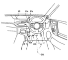
- FIG. 1 is a view showing a layout around a driver's seat of a vehicle, showing a footrest device mounted on a vehicle
- FIG. 2 is a block diagram showing a vibration presentation system including a footrest device together with a vehicle system etc.
- FIG. 3 is a perspective view showing the structure of the footrest device
- FIG. 4 is a plan view of the footrest device, showing the arrangement of the presentation surface portion on the mounting surface
- 5 is a cross-sectional view taken along the line V-V of FIG. FIG.
- FIG. 6 is a diagram showing the relationship between the points of the soles and their distances necessary to define the arrangement of the presentation surfaces
- FIG. 7 is a diagram showing the structure and operation principle of the vibration speaker
- FIG. 8 is a state transition diagram showing an overview of transition of the operation mode of the footrest device
- FIG. 9 is a flowchart showing the details of a request degree presentation process of switching the vibration interval in the request degree presentation mode according to the driving participation request degree
- FIG. 10A is a diagram showing control of the vibration speaker when the driving participation request degree is “low” in the request degree presentation mode
- FIG. 10B is a time chart showing control of the vibration speaker when the degree of driving participation request is “low” in the request degree presentation mode
- FIG. 10A is a
- FIG. 11A is a diagram showing control of the vibration speaker when the driving participation request degree is “high” in the request degree presentation mode
- FIG. 11B is a diagram of a time chart showing control of the vibration speaker when the degree of driving participation request in the request degree presentation mode is “high”
- FIG. 12A is a diagram showing details of control of each vibration speaker in the driving action induction mode
- FIG. 12B is a diagram of a time chart showing details of control of each vibration speaker in the driving action induction mode
- FIG. 13 is a flowchart showing details of transition control processing for controlling switching of the operation mode between the request degree presentation mode and the prior presentation mode
- FIG. 14 is a flowchart showing the details of the prior presentation process of switching the control of each vibration speaker in the prior presentation mode according to the content of the behavior change scheduled in the travel plan
- FIG. 15A is a diagram showing control of each vibration speaker in the acceleration operation presentation
- FIG. 15B is a diagram of a time chart showing control of each vibration speaker in the acceleration operation presentation
- FIG. 16A is a diagram showing control of each vibration speaker in the deceleration operation presentation
- FIG. 16B is a diagram of a time chart showing control of each vibration speaker in the deceleration operation presentation
- FIG. 17A is a diagram showing control of each vibration speaker in the right turn presentation
- FIG. 17B is a diagram of a time chart showing control of each vibration speaker in the right turn presentation
- FIG. 18A is a diagram showing control of each vibration speaker in the left turning motion presentation
- FIG. 18B is a diagram of a time chart showing control of each vibration speaker at the time of presentation of a left turn
- FIG. 19A is a diagram showing control of the vibration speaker in the requested degree presentation mode according to the second embodiment
- FIG. 19B is a diagram of a time chart showing control of the vibration speaker in the requested degree presentation mode according to the second embodiment
- FIG. 20A is a diagram showing control of each vibration speaker in the right turning operation presentation according to the second embodiment
- FIG. 20B is a diagram of a time chart showing control of each vibration speaker in the right turning operation presentation according to the second embodiment
- FIG. 21A is a diagram showing control of each vibration speaker in the left turning operation presentation according to the second embodiment
- FIG. 21B is a diagram of a time chart showing control of each vibration speaker at the time of presenting the left turning motion according to the second embodiment
- FIG. 22A is a diagram showing control of each vibration speaker at the time of presenting the right turn operation according to the third embodiment
- FIG. 22B is a diagram of a time chart showing control of each vibration speaker at the time of presenting the right turn operation according to the third embodiment
- FIG. 23A is a diagram showing control of each vibration speaker in the left turning operation presentation according to the third embodiment
- FIG. 23B is a diagram of a time chart showing control of each vibration speaker in the left turning operation presentation according to the third embodiment
- FIG. 24A is a diagram showing control of each vibration speaker in composite action presentation
- FIG. 24B is a diagram of time charts showing control of the respective vibration speakers in composite action presentation.
- the function of the information presentation control device is realized by a human machine interface control unit (HCU) 40.
- the HCU 40 constitutes a vibration presentation system together with the footrest device 100 and the drive device 60 and the like.
- the vibration presentation system is mounted on a vehicle capable of autonomous driving, and performs information presentation to a user (hereinafter referred to as a driver) seated on the driver's seat 11 of the vehicle by vibration.
- the footrest device 100 is one of a plurality of HMI (Human Machine Interface) devices mounted on a vehicle.
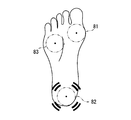
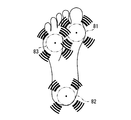
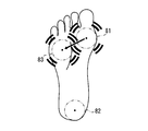
- the footrest device 100 has a plurality of presentation surface portions 81a to 83a on a mounting surface 73 on which the placement of the soles of the driver riding the vehicle is assumed.
- the footrest device 100 presents information mainly related to the automatic driving of the vehicle through the sense of the sole of the driver, specifically the sense of vibration, by the vibration of the presentation surface portions 81a to 83a.
- the footrest device 100 is formed in a longitudinal plate shape as a whole.
- the footrest device 100 is attached to the mounting portion 16 provided on the vehicle in a posture in which the mounting surface 73 on which the left foot of the driver is placed is directed to the driver's seat 11 side.
- the longitudinal direction LD of the mounting surface 73 is along a vertical cross section perpendicular to the front-rear direction and the vertical direction of the vehicle.
- the width direction (also referred to as the short side direction) CD of the mounting surface 73 is along the left-right direction of the vehicle.
- the mounting surface 73 is inclined upward as it goes from the rear to the front of the vehicle.
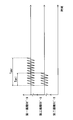
- the footrest device 100 is configured of a footrest base 70 and a plurality of (three) vibration speakers 81 to 83 and the like.
- the vibration speakers 81 to 83 are also referred to as first to third vibration speakers, respectively.
- the footrest base 70 is fixed to the mounting portion 16 of the vehicle by a fastening member such as a bolt.
- the footrest base 70 is configured of an upper cover member 71, a lower base plate 76, a base cushioning material 78, a speaker cushioning material 79, and the like.
- the upper cover member 71 is formed by affixing a thin plate-like decorative plate 72 on the bottom surface of a base having a shallow container shape with a bottom.
- the upper cover member 71 is formed of a metal material as a whole.
- the upper cover member 71 has a support wall 71a and a bottom wall 71b.
- the support wall 71a is provided on the outer edge of the bottom wall 71b, and is erected substantially perpendicularly to the bottom wall 71b.
- the support wall 71 a defines the distance between the bottom wall 71 b and the lower base plate 76.
- the bottom wall 71 b forms a mounting surface 73 which is long and flat.
- the bottom wall 71 b is provided with an insertion opening 74.
- the insertion opening 74 is a perfect circular opening that penetrates the bottom wall portion 71 b including the decorative plate 72 in the thickness direction. Three insertion openings 74 are opened in the bottom wall portion 71b in a mutually space
- the lower base plate 76 is formed in a flat plate shape by a metal material.
- the outer shape of the lower base plate 76 is substantially the same as the bottom wall 71 b of the upper cover member 71.
- the lower base plate 76 is located on the opposite side of the mounting surface 73 with respect to the upper cover member 71.
- the top of the support wall 71 a is in contact with the outer edge of the lower base plate 76.
- the lower base plate 76 holds the three vibration speakers 81 to 83 individually.
- the base cushioning material 78 is formed of, for example, urethane or the like in a sheet shape thicker than the lower base plate 76.
- the base cushioning material 78 is disposed between the lower base plate 76 and the mounting portion 16 in a compressed state in the thickness direction.
- the footrest base 70 is firmly fixed to the mounting portion 16 via the base cushioning material 78.
- the vibration of the lower base plate 76 caused by the operation of each vibration speaker 81 to 83 is considered to be fixed end reflection at the boundary between the lower base plate 76 and the base cushioning material 78.
- the vibration of the footrest base 70 is reduced by the substantial cancellation of the incident wave and the reflected wave that are in antiphase with each other.
- the speaker cushioning material 79 is formed in a cylindrical shape by, for example, a sponge or the like which is excellent in flexibility.
- the speaker cushioning material 79 is externally fitted to a member (for example, a screw, a bolt, a pin, or the like) that fixes the vibration speakers 81 to 83 to the lower base plate 76.
- the speaker cushioning material 79 functions as an elastic body between the vibration speakers 81 to 83 and the lower base plate 76, and reflects the vibration generated in each of the vibration speakers 81 to 83 at its free end. As a result, the amplitude of the composite wave (the standing wave) of the incident wave and the reflected wave in the same phase is increased.
- the vibration speakers 81 to 83 are held by the lower base plate 76 in a mutually spaced arrangement.
- the vibration speakers 81 to 83 are fixed in a floating state from the lower base plate 76 by the interposition of the speaker cushioning material 79.
- the vibration speakers 81 to 83 have presentation surface portions 81a to 83a, respectively.
- the presentation surface portions 81a to 83a vibrate in a direction substantially perpendicular to the mounting surface 73, and vibrate the sole of the driver placed on the mounting surface 73.
- the vibration of the presentation surface portions 81a to 83a is a push-up vibration that pushes up the bottom of the driver's footwear, and can be transmitted to the driver's sole through the driver's footwear.
- the vibrations of the individual presentation surfaces 81a to 83a are individually controlled.
- the presentation surface portions 81a to 83a are exposed through the respective insertion openings 74 at places different from each other on the placement surface 73.
- the presentation surface portions 81a to 83a project further than the upper cover member 71 in the direction in which the placement surface 73 faces.
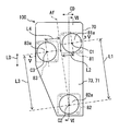
- the presentation surface portions 81a to 83a are exposed to the placement surface 73 in a mutually offset arrangement with respect to each of the longitudinal direction LD and the width direction CD.
- the two presentation surfaces 81a and 82a are arranged along the longitudinal direction LD of the mounting surface 73, and the two presentation surfaces 81a and 83a are arranged along the width direction CD of the mounting surface 73.
- the presentation surface 83a is located between the presentation surface 81a and the presentation surface 82a in the longitudinal direction LD, and the presentation surface 82a is located between the presentation surface 81a and the presentation surface 83a in the width direction CD. doing.
- the presentation surface portions 81a to 83a are respectively the heel center C2, the base of the thumb (hereinafter, the ball ball center C1) and the base of the little finger (hereinafter, the small finger ball center C3) It is placed in a position where you can touch naturally.
- the presentation surface part 81a is provided in the range where placement of the center C1 of the ball of the driver of the driver and the periphery (the ball part of the finger) on the placement surface 73 is assumed.
- the presentation surface portion 82 a is provided in a range where placement of the crucible center C 2 and the periphery (ridge portion) thereof is assumed on the placement surface 73.
- the presentation surface portion 83a is provided in a range in which placement of the little toe ball center C3 and the periphery (the little toe portion) on the placement surface 73 is assumed.
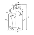
- a foot length FL, a heel point HP, a second finger tip FT, a shin side middle foot point SFP and a heel side middle foot point CFP can be defined on the sole. Then, a virtual line connecting the heel point HP and the second finger tip FT is the foot axis Af. Further, the distance between the heel point HP and the shin mid-foot point SFP is the inner non-step length IL, and the distance between the heel point HP and the mid-side mid-foot point CFP is the outer non-step length FIL. Furthermore, the distance between the shin side midfoot point SFP and the foot axis Af is within the half foot width HWi, and the distance between the heel side midfoot point CFP and the foot axis Af is half foot outside HWo.
- the heel center C2 is defined from the heel point HP at a position on the foot axis Af which is “foot length FL ⁇ 0.18 (refer to L0)” in the toe direction.
- the ball ball center C1 is a position "inward step length IL” in the toe direction from the heel point HP, and is a position "in in half foot width HWi x 0.5" in the inward direction of the foot.
- the small toe ball center C3 is a position "outside step length FIL" in the toe direction from the heel point HP, and is a position "half foot width outside x 0.5" in the outward direction of the foot.
- the presentation surface 82a is assumed to excite the crucible center C2, and is disposed at a position closer to the rear end than the front end, of both ends of the mounting surface 73 in the longitudinal direction LD.
- the positions of the presentation surface portions 81a and 83a are defined based on a state in which the eyebrow center C2 overlaps the center of the presentation surface portion 82a.
- the center of the presentation surface 81a assumed to excite the ball C1 is disposed at a position L1 from the center of the presentation surface 82a to the tip of the toe and at a position L2 in the inward direction of the foot from the foot axis Af It is done.
- L1 is a value obtained by subtracting L0 (see FIG. 6) from the inner step length IL, and is defined to, for example, about 136.8 mm.
- L2 is half the value of HWi within the half width, and is defined to be, for example, 23.1 mm.
- the center of the presentation surface 83a assumed to excite the small toe ball center C3 is disposed at a position L3 from the center of the presentation surface 82a in the toe direction and at a position L4 from the foot axis Af outward of the foot ing.
- L3 is a value obtained by subtracting L0 (see FIG. 6) from the outer non-stepping length FIL, and is defined to, for example, about 112.9 mm.
- L4 is half the value of the half-foot-wide HWo, and is defined to be, for example, about 26.9 mm.
- the dimensions L1 to L4 are an example of values based on the data of the foot size measurement business report published by the Japan Leather Industry Association.
- the protrusion amounts of the presentation surface portions 81a to 83a from the insertion opening 74 are different from each other.
- the protrusion amount of the presentation surface portion 83a in the vibration speaker 83 far from the center line DCL (see FIG. 1) of the driver's seat 11 along the longitudinal direction of the vehicle is larger than the protrusion amount of the presentation surface portion 81a in the vibration speaker 81 near the center line DCL It is done.
- the protrusion amount of the presentation surface portion 83a provided in the outer range of the mounting surface 73 where the placement of the outer part of the sole is assumed is the placement surface where the placement of the inner part of the sole is assumed It is larger than the protrusion amount of the presentation surface 81 a provided in the inner area 73.
- the protrusion amount of the presentation surface 82a in the vibration speaker 82 is larger than the protrusion amount of the presentation surface 81a, 83a in the other vibration speakers 81, 83.
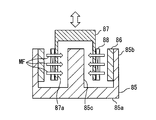
- the vibration speakers 81 to 83 are configured by a housing 84, a yoke 85, a vibrating body 87, an attachment 89, and the like, as shown in FIGS.
- the housing 84 is formed in a container shape, for example, of a resin material or the like.
- the housing 84 has a flat square pole shape.
- the housing 84 accommodates the yoke 85 and the vibrator 87.
- the yoke 85 is formed of a magnetic metal material in a bottomed container shape.
- the yoke 85 is formed with a bottom wall 85a, an outer peripheral wall 85b, and a central wall 85c.
- a magnet 86 is provided on the inner peripheral side of the outer peripheral wall 85 b.
- the magnet 86 forms a magnetic field MF which goes around the outer peripheral wall 85 b, the center wall 85 c and the bottom wall 85 a.
- the vibrating body 87 is formed in a cylindrical shape with a bottom.
- a coil 88 is provided on the outer peripheral surface of the cylindrical wall 87 a of the vibrating body 87.
- the coil 88 is arranged in the magnetic field MF formed by the yoke 85 and the magnet 86.
- a drive signal is applied to the coil 88 by any one of the amplifiers 62a to 62c of the drive device 60. By applying the drive signal to the coil 88, an electromagnetic force in the axial direction acts on the vibrating body 87.
- the vibrating body 87 is axially displaced relative to the yoke 85 to exert a stress on the attachment 89.
- the attachment 89 is formed of a flexible material such as a rubber material.
- the attachment 89 is attached to the housing 84 and blocks the opening of the housing 84.
- the attachment 89 forms presentation surface portions 81a to 83a which are convexly curved.
- the curvature of the cross section of the attachment 89 gradually decreases from the outer edge toward the radial center.
- each of the presentation surface portions 81a to 83a brings the central portion into surface contact with the bottom surface (foot sole) of the footwear.
- the height of the attachment 89 is different for each of the vibration speakers 81 to 83. By making the heights of the attachments 89 different, the amount of protrusion of the presentation surface portions 81a to 83a from the insertion opening 74 is adjusted.
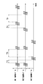
- the drive device 60 operates the footrest device 100 based on a control signal input from the HCU 40, as shown in FIG.
- the driving device 60 is configured to drive the respective vibration speakers 81 to 83 of the footrest device 100, and includes a plurality of (three) digital-analog converters (hereinafter, D / A converters) 61a to 61c; And amplifiers 62a to 62c).
- D / A converters digital-analog converters
- the number of D / A converters 61a to 61c and amplifiers 62a to 62c is equal to the number of vibration speakers 81 to 83 so that the vibrations of the presentation surfaces 81a to 83a of the vibration speakers 81 to 83 can be individually controlled. I do.
- the D / A converters 61a to 61c are electric circuits that convert digital type electric signals into analog type electric signals.
- the D / A converters 61a to 61c are electrically connected to the HCU 40 and the amplifiers 62a to 62c.
- the D / A converters 61a to 61c convert control signals input from the HCU 40 into analog signals, and output the converted signals to the amplifiers 62a to 62c.
- the amplifiers 62a to 62c are electric circuits that output a voltage or current proportional to the input signal.
- the amplifiers 62a to 62c are electrically connected to the D / A converters 61a to 61c and the vibration speakers 81 to 83, respectively.
- the amplifiers 62a to 62c generate drive signals by amplifying analog signals input from the D / A converters 61a to 61c.
- the amplifiers 62a to 62c drive the vibration speakers 81 to 83 by applying the generated drive signals to the vibration speakers 81 to 83.
- the HCU 40 is one of a plurality of electronic control units mounted on a vehicle, as shown in FIGS. 1 and 2.
- the HCU 40 is electrically connected to the drive device 60 and controls the operation of the footrest device 100 together with the drive device 60.
- the HCU 40 is communicably connected to the in-vehicle network 30.
- the HCU 40 acquires information from the vehicle system 20 via the in-vehicle network 30.
- the vehicle system 20 includes an electronic control unit that enables autonomous traveling of the vehicle, various on-vehicle sensors that detect the state of the vehicle, and communication devices that communicate with the outside of the vehicle.
- the control circuit of the HCU 40 mainly includes a computer having a processing unit 41, a storage unit 42, a RAM 43, and the like.
- the processing unit 41 is configured to include at least one of a central processing unit (CPU), a graphics processing unit (GPU), and a field-programmable gate array (FPGA).
- the processing unit 41 executes various arithmetic processing.
- the storage unit 42 is configured to include a non-volatile storage medium.
- the storage unit 42 stores various programs including an information presentation control program so that the processing unit 41 can read them.
- a random access memory (RAM) 43 is a volatile semiconductor memory.
- the RAM 43 functions as a work area of calculation processing by the processing unit 41.
- the HCU 40 constructs a plurality of functional blocks by causing the processing unit 41 to execute the information presentation program stored in the storage unit 42. Specifically, in the HCU 40, an information acquisition unit 51, a mode transition control unit 52, a signal output unit 53, and the like are constructed as functional blocks that control the footrest device 100.
- the information acquisition unit 51 acquires various information related to the vehicle, such as map data around the vehicle, current vehicle speed data, and steering angle data, from the vehicle system 20.
- the information acquisition unit 51 can acquire various information of a system related to the automatic driving of the vehicle (hereinafter, an automatic driving system).
- the information acquisition unit 51 acquires status information indicating start and stop of the automatic driving function, and a travel plan for realizing autonomous traveling by the automatic driving function.
- status information of the automatic driving system for example, information indicating the reception sensitivity of positioning signals transmitted from positioning satellites of the Global Navigation Satellite System (GNSS), status information indicating the detection status of external sensors such as cameras and lidar, etc. Is acquired by the information acquisition unit 51.
- GNSS Global Navigation Satellite System
- the mode transition control unit 52 switches the operation of the footrest device 100 based on the information acquired by the information acquisition unit 51. Specifically, the mode transition control unit 52 starts information presentation using the footrest device 100 with switching from manual operation to automatic operation (automatic operation ON) based on status information of automatic operation. Then, with the switching from the automatic driving to the manual driving (automatic driving OFF), the information presentation using the footrest device 100 is stopped.
- the mode transition control unit 52 switches the operation mode of the footrest device 100. Specifically, in the mode transition control unit 52, two request degree presentation modes, a driving behavior induction mode and a preceding presentation mode are set in advance as a plurality of operation modes (see FIG. 8). The mode transition control unit 52 causes the operation mode of the footrest device 100 to transition based on the information acquired by the information acquisition unit 51. When the manual operation is switched to the automatic operation, the mode transition control unit 52 first selects the request degree presentation mode.
- the demand degree presentation mode is an operation mode that presents the degree of demand for driving participation to the driver from the automatic driving function, and generates a simulated heartbeat of the automatic driving system, and is reproduced by the vibration of the presentation surface 82a. This is an operation mode in which the driver is biofeedbacked.
- the mode transition control unit 52 determines the degree of request for the driver's participation in driving based on the state information of the automatic driving system.
- the mode transition control unit 52 determines that the driving participation degree is "high". The mode transition control unit 52 switches between a requested degree presentation mode in which the requested degree of driving participation is “low” and a requested degree presentation mode in which the requested degree of driving participation is “high” based on the degree of requested degree of driving participation. .
- the driving behavior induction mode is an operation mode that urges a driver who is away from driving behavior during automatic driving to start driving behavior.
- the mode transition control unit 52 causes the operation mode to transition from the requested degree presentation mode to the driving action induction mode when the automatic driving system is in the specific state.
- the specific state is a state in which a drive change request (Take-Over Request) from the automatic driving function to the driver is generated in the travel plan.
- a driving shift request is generated.
- the driving behavior induction mode causes the operation mode to transition from the driving behavior induction mode to the request degree presentation mode with the end of the predefined induction operation.
- the advance presentation mode is an operation mode in which the driver is notified in advance of the contents of the behavior change that will occur before the behavior change occurs in the autonomously traveling vehicle.
- the mode transition control unit 52 changes the behavior to be presented to the driver (hereinafter referred to as presentation behavior change), for example, after several seconds (about 1 to 3 seconds) based on the travel plan showing the future behavior of the autonomously traveling vehicle. It is determined whether or not it occurs in the vehicle.
- presentation behavior change for example, after several seconds (about 1 to 3 seconds) based on the travel plan showing the future behavior of the autonomously traveling vehicle. It is determined whether or not it occurs in the vehicle.
- a scene where a presentation behavior change occurs (hereinafter, referred to as a prior presentation scene) is, for example, a scene in which the driver performs acceleration / deceleration such as anxiety, and turning to the left and right and lane change.
- the mode transition control unit 52 changes the operation mode from the request degree presentation mode to the advance presentation mode when the advance presentation scene is scheduled in the travel plan. Then, in the advance presentation mode, a notice of the contents of the presentation behavior change using the plurality of presentation surface parts 81a to 83a is carried out, and the notice is ended before the behavior change of the vehicle occurs. When the presentation operation of the future behavior corresponding to the presentation behavior change is finished, the mode transition control unit 52 causes the operation mode to transition from the preceding presentation mode to the request degree presentation mode.
- the signal output unit 53 generates a control signal for controlling the operation of the footrest device 100. Control signals corresponding to each operation mode are defined in advance in the signal output unit 53. The signal output unit 53 generates a control signal corresponding to the operation mode selected by the mode transition control unit 52 and the information acquired by the information acquisition unit 51, and directs the generated control signal to the drive device 60. Output.
- the request degree presentation process shown in FIG. 9 is started by the signal output unit 53 by the transition of the operation mode to the request degree presentation mode accompanying the start of the automatic driving.
- the request degree presentation process is repeated by the signal output unit 53 until the automatic operation is stopped.
- the signal output unit 53 operates the respective vibration speakers 81 to 83 in the vibration pattern defined in the driving action induction mode or the advance presentation mode. Prioritize.
- the setting of the interval Tin1 (see FIGS. 10A and 10B) in the case where the degree of driving participation request is “low” is acquired from the storage unit 42 as the initial setting, and the process proceeds to S102.
- the interval Tin1 may be a value preset at the time of design of the system, or may be a value set by the user of the vehicle.
- S102 based on the status information of the automatic driving acquired by the information acquiring unit 51, it is determined whether the automatic driving is in the on state. If it is determined in S102 that the automatic driving is in the OFF state, the process proceeds to S108, and the operation of the vibration speakers 81 to 83 is stopped. On the other hand, when it is determined in S102 that the automatic driving on state is continued, the process proceeds to S103.
- S103 the operation of the vibration speaker 82 is started with the setting of the acquired latest interval (see FIG. 10A, FIG. 10B and FIG. 11A, FIG. 11B), and the process proceeds to S104.
- S104 the latest driving participation request degree determined by the mode transition control unit 52 is acquired, and the process proceeds to S105.
- S105 it is determined whether the driving participation request degree acquired in S104 is "high". When the driving participation request degree acquired in S104 is "high”, the process proceeds from S105 to S106. On the other hand, when the driving participation request degree acquired in S104 is "low”, the process proceeds from S105 to S107.
- the setting of the interval Tin2 (see FIGS. 11A and 11B) when the degree of driving participation request is “high” is acquired from the storage unit 42, and the process returns to S102.
- the interval Tin2 in this case may also be a value preset at the time of system design, or may be a value set by the user of the vehicle, as in the case where the degree of driving participation request is "low”.
- the setting of the interval Tin1 (see FIGS. 10A and 10B) in the case where the degree of driving participation request is “low” is acquired from the storage unit 42, and the process proceeds to S102.
- the request degree presentation mode when the driving participation request degree is "low” and the request degree presentation mode when the driving participation request degree is "high” are risk occurrence and disappearance It switches according to the state change of the automatic driving system resulting from. Details of control of the vibration speaker 82 in the request degree presentation mode will be described based on FIG. 10A, FIG. 10B and FIG. 11A and FIG. 11B.
- each requested degree presentation mode only the vibration speaker 82 provided to be in contact with the heel portion operates, and the two vibration speakers 81 and 83 on the toe side maintain the stopped state.
- the signal output unit 53 causes the vibration speaker 82 to generate pulsation by control of repeating on and off of the vibration of the vibration speaker 82, and presents the driver with the state of the automatic driving system. Pulsation is a vibration that mimics the human heartbeat.
- the on time Ton of the vibration of the vibration speaker 82 is substantially the same regardless of the driving participation request level.
- one rectangular wave is input as a drive signal from the drive device 60 to the vibration speaker 82.
- the push-up vibration of the vibration speaker 82 due to the input of the rectangular wave can remind the driver of a feeling close to the heartbeat of a human heart.
- the vibration intervals Tin1 and Tin2 are changed according to the level of the driving participation request degree as described above.
- the interval Tin2 when the driving participation request degree is “high” is defined shorter than the interval Tin1 when the driving participation request degree is “low”. That is, the off time of the vibration when the driving participation request degree is “high” is shorter than the off time when the driving participation request degree is “low”.
- the signal output unit 53 discretely changes the intervals Tin1 and Tin2 so that the off time is shorter as the request degree is higher based on the level of the operation participation request degree as the system state information.
- the cycle of pulsing the presentation surface 82a is varied.
- the "higher degree of request” includes “the state of high request degree".
- the vibration at interval Tin1 when the degree of driving participation request is “low” is set based on the heart rate at a human resting time (for example, about 60 times per minute), specifically about 1 hertz Is repeated.
- the vibration due to the interval Tin 2 when the driving participation request level is “high” is set based on the heart rate at the time of rising of the human (for example, about 160 times per minute), specifically 2.6 hertz It is repeated by the degree.
- the transition from the demand degree presentation mode to the driving behavior induction mode is mainly performed based on the driving shift request from the autonomous driving system.
- the number of presentation surface portions 81a to 83a to be vibrated is increased compared to the request degree presentation mode.
- the three vibration speakers 81 to 83 are synchronously controlled, and the on and off timings of the vibrations in the three presentation surface portions 81a to 83a are synchronized.
- the signal output unit 59 causes all the vibration speakers 81 to 83 to repeat the on and off of the vibration.
- the time ratio (on-duty ratio) occupied by the on-time Ton in the drive signal is set to, for example, about 15%.
- the signal waves input to each of the vibration speakers 81 to 83 in the on time Ton of the driving action induction mode are continuous triangular waves whose falling time is shorter than the rising time.
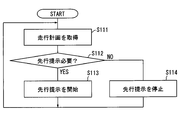
- the transition control process shown in FIG. 13 is started by the HCU 40 along with the start of the automatic operation in the same manner as the request degree presentation process (see FIG. 9), and performs transition of the operation mode between the request degree presentation mode and the preceding presentation mode. .
- the transition control process is repeated by the HCU 40 until the automatic operation is stopped.
- the travel plan formulated by the automatic driving function is acquired, and the process proceeds to S112.
- S112 based on the travel plan acquired in S111, it is determined whether or not the prior presentation is necessary.
- the process proceeds from S112 to S113.
- S113 by switching from the request degree presentation mode to the advance presentation mode, the footrest device 100 starts an advance presentation, and the process returns to S111.
- S114 the advance presentation is stopped by switching from the advance presentation mode to the request degree presentation mode, and the process returns to S111.
- the preceding presentation process shown in FIG. 14 is started.
- the advance presentation process the advance presentation scene scheduled next is determined, and an actuation corresponding to the next vehicle behavior is set.
- S121 based on whether or not an acceleration exceeding the acceleration threshold is to be generated in the forward direction of the vehicle, it is determined whether or not the presentation of the acceleration operation is necessary. When it is determined that the acceleration in the forward direction in the assumed preceding presentation scene is equal to or less than the acceleration threshold and the presentation of the acceleration operation is unnecessary, the process proceeds from S121 to S123. On the other hand, when it is determined that the acceleration in the forward direction of the vehicle exceeds the acceleration threshold, the process proceeds from S121 to S122. In S122, the footrest device 100 starts the advance presentation operation (hereinafter referred to as acceleration operation presentation, see FIGS. 15A and 15B) for giving a notice of the acceleration operation of the vehicle, and ends the advance presentation process.
- acceleration operation presentation hereinafter referred to as acceleration operation presentation, see FIGS. 15A and 15B
- S123 based on whether or not an acceleration exceeding the deceleration threshold is to be generated in the backward direction of the vehicle, it is determined whether or not the presentation of the deceleration operation is necessary. When it is determined that the backward acceleration in the assumed preceding presentation scene is equal to or less than the deceleration threshold and presentation of the deceleration operation is unnecessary, the process proceeds from S123 to S125. On the other hand, when it is determined that the backward acceleration of the vehicle exceeds the deceleration threshold, the process proceeds from S123 to S124. In S124, the footrest device 100 starts the advance presentation operation (hereinafter referred to as deceleration operation presentation, see FIGS. 16A and 16B) for giving a notice of the deceleration operation of the vehicle, and the advance presentation process is ended.
- deceleration operation presentation see FIGS. 16A and 16B
- S125 based on whether acceleration exceeding the turning threshold is to be generated in the right direction of the vehicle, it is determined whether it is necessary to present the turning operation in the right direction. If it is determined that the acceleration in the right direction in the assumed preceding presentation scene is equal to or less than the turning threshold and presentation of the turning operation in the right direction is required, the process proceeds from S125 to S126.
- the footrest device 100 causes the footrest device 100 to start an advance presentation operation (hereinafter, right rotation operation presentation, see FIGS. 17A and 17B) for giving a notice of right rotation operation of the vehicle, and ends the advance presentation process.
- an advance presentation operation hereinafter, right rotation operation presentation, see FIGS. 17A and 17B
- the process proceeds from S125 to S127.
- the footrest device 100 starts the advance presentation operation (hereinafter referred to as left rotation operation presentation, see FIG. 18A, FIG. 18B) for giving a notice of the left rotation operation of the vehicle, and ends the advance presentation process.
- the acceleration operation presentation shown in FIGS. 15A and 15B is performed when it is determined that the vehicle is accelerated in the forward direction.
- vibration speakers 81 and 83 (hereinafter referred to as front speaker group 80f) disposed on the front side of the driver and in the front direction of the vehicle are integrally and synchronously controlled.
- the signal output unit 59 alternately vibrates the vibration speaker 82 disposed on the rear side of the vehicle on the heel side of the driver and the above-described front speaker group 80f at predetermined time intervals.
- the time interval from the stop of the vibration of the vibration speaker 82 to the start of the vibration of the front speaker group 80f is the first off time T1f.
- the time interval from the stop of the vibration of the front speaker group 80f to the start of the vibration of the vibration speaker 82 is the second off time T2f.
- the signal output unit 59 sets the first off time T1f shorter than the second off time T2f. By setting each of the off times T1f and T2f, the vibration of the series of vibration speakers 81 to 83 reminds the driver of an image pushed forward.
- the deceleration operation presentation shown in FIGS. 16A and 16B is performed when it is determined that the vehicle is accelerated in the backward direction. Even in the deceleration operation presentation, the front speaker group 80f is integrally and synchronously controlled. The signal output unit 59 alternately vibrates the front speaker group 80 f and the vibration speaker 82 at time intervals different from the acceleration operation presentation.
- the time interval from the stop of the vibration of the front speaker group 80f to the start of the vibration of the vibration speaker 82 is taken as a first off time T1b.
- the time interval from the stop of the vibration of the vibration speaker 82 to the start of the vibration of the front speaker group 80f is taken as a second off time T2b.
- the signal output unit 59 sets the first off time T1b shorter than the second off time T2b.
- the on time of the vibration of the front speaker group 80f and the on time of the vibration of the vibration speaker 82 are substantially the same.
- the vibration intensity (amplitude) of the front speaker group 80f and the vibration intensity (amplitude) of the vibration speaker 82 are also substantially the same.
- the right turn operation presentation shown in FIGS. 17A and 17B is performed when it is determined that acceleration in the right direction is generated in the vehicle.
- the right turn motion presentation only the two vibration speakers 81, 82 aligned in the width direction CD operate, and the vibration speaker 82 on the heel side maintains the stop state.
- the signal output unit 59 alternately vibrates the two vibration speakers 81 and 82 at predetermined time intervals.
- the time interval from the stop of the vibration of the vibration speaker 83 located on the left to the start of the vibration of the vibration speaker 83 located on the right is taken as the first off time T1r.
- the time interval from the stop of the vibration of the vibration speaker 81 located on the right to the start of the vibration of the vibration speaker 83 located on the left is taken as a second off time T2r.
- the signal output unit 59 sets the first off time T1r to be shorter than the second off time T2r. By setting each of the off times T1r and T2r, the vibration of the series of vibration speakers 81 and 82 reminds the driver of an image moving to the right.
- the left turn action presentation shown in FIGS. 18A and 18B is performed when it is determined that acceleration in the left direction occurs in the vehicle.
- the signal output unit 53 alternately vibrates the two vibration speakers 81 and 82 at a predetermined time interval while maintaining the stop state of the vibration speaker 82 on the heel side also in the left turning motion presentation.
- the time interval from the stop of the vibration of the vibration speaker 81 located on the right side of the two to the start of the vibration of the vibration speaker 83 located on the left side of the two is the first off time T1l. Be done.
- the time interval from the stop of the vibration of the vibration speaker 83 located on the left to the start of the vibration of the vibration speaker 81 located on the right is taken as the second off time T21.
- the signal output unit 59 sets the first off time T1 l shorter than the second off time T2 l. By setting each of the off times T11 and T21, the vibration of the series of vibration speakers 81 and 82 reminds the driver of an image moving to the left.
- the on time and strength (amplitude) of the vibration of the two vibration speakers 81 and 83 are substantially the same. Furthermore, the signal waves input to the respective vibration speakers 81 to 83 in each presentation operation are continuous triangular waves whose fall time is shorter than the rise time. With such a waveform of the drive signal, vibrations that push up the sole are transmitted from the respective presentation surface portions 81a to 83a to respective positions on the sole.
- the vibrations of the plurality of presentation surfaces 81a to 83a are individually controlled, it is possible to notify the driver of the contents of the behavior change that will occur to the autonomously traveling vehicle in the future.
- the mechanism for moving the footrest or the like can be omitted if the behavior can be notified by vibration in the future. Therefore, while ensuring the mountability of the configuration for information presentation to the vehicle, it becomes possible to notify the user of the behavior change through the somatic feeling.
- the posture of the driver sitting on the driver's seat 11 changes temporarily, and the posture of the footrest can be changed even if a large gap occurs in the driver's trunk.
- the ease of transmission of the information presentation to the driver as compared to the changing form can be maintained. That is, the information presentation by vibration is easier to ensure tolerance to trunk displacement than the information presentation by the posture change of the footrest.
- the signal output unit 53 sets at least two of the plurality of presentation surface units 81 a to 83 a along the direction of the acceleration to be generated. Vibrate alternately. According to such control, even if the footrest device 100 has a simple configuration, the driver can be easily notified of the direction of the acceleration generated in the vehicle by the future behavior change.
- the first off time T1f from the stop of the vibration of the vibration speaker 82 to the start of the vibration of the front speaker group 80f is the start of the vibration of the vibration speaker 82 after the stop of the vibration of the front speaker group 80f. It is defined to be shorter than the second off time T2f.
- each of the first off-times T1 b, T1 r, T1 l is shorter than the respective second off-times T2 b, T2 r, T2 l in each of the deceleration action presentation, the right turning action presentation, and the left turning action presentation. .
- the longitudinal and lateral directions of the acceleration to be generated in the vehicle Can be notified to the person in a more understandable manner.
- the advance notice of the contents of the behavior change due to the vibration of each of the presentation surface portions 81a to 83a is ended before the behavior change occurs in the vehicle.
- the driver can easily grasp the timing from the advance notice to the start of the behavior change. Therefore, the notification of the behavior change to the driver through somatic sensation can be information presentation that is easy for the driver to understand.
- the HCU 40 corresponds to the “information presentation control device”
- the mode transition control unit 52 corresponds to the “behavior determination unit”
- the signal output unit 53 corresponds to the “presentation control unit”.
- the travel plan corresponds to "behavior information”.
- presentation surface part 81a, 83a corresponds to a "1st presentation surface part”
- the other (remaining) presentation surface part 82a corresponds to a "2nd presentation surface part.”
- the presentation surface 82a corresponds to the "first presentation surface”
- the presentation surfaces 81a and 83a correspond to the "second presentation surface”.
- the presentation surface 81a corresponds to the "first presentation surface” and the presentation surface 83a corresponds to the "second presentation surface”
- the presentation surface 83a is It corresponds to a "1st presentation surface part”
- the presentation surface part 81a corresponds to a "2nd presentation surface part.”
- the second embodiment of the present disclosure shown in FIGS. 19A to 21B is a modification of the first embodiment.
- the vibration patterns of the respective vibration speakers 81 to 83 are different from those of the first embodiment.
- the magnitude of the amplitude is also changed according to the request degree of the driving participation.
- the amplitude see solid line
- the amplitude when the degree of request for driving participation is “high” is from the amplitude (see the alternate long and short dashed line) when the degree of request for driving participation is “low”. Is also enlarged.
- the vibration of the three vibration speakers 81 to 83 is simultaneously started.
- the on time Tonr for continuing the vibration of the vibration speaker 81 is set to about twice the on time Tonl for continuing the vibration of the vibration speakers 82 and 83. It is done. That is, after the vibration of the vibration speakers 81 to 83 is started, the signal output unit 53 (see FIG. 2) stops the vibration of the vibration speakers 82 and 83 earlier than the vibration speaker 81.
- the vibration of the series of vibration speakers 81 to 83 makes use of the aftermath of the vibration of the vibration speakers 82 and 83 stopped earlier to move the image moving rightward to the driver. Remind me.
- the vibration patterns of the vibration speakers 81 to 83 may be repeated a plurality of times at predetermined time intervals as the right turning operation presentation.
- the on time Ton1 for continuing the vibration of the vibration speaker 83 is set to about twice the on time Tonr for continuing the vibration of the vibration speakers 81 and 82. That is, after the vibration of the vibration speakers 81 to 83 is started, the signal output unit 53 (see FIG. 2) stops the vibration of the vibration speakers 81 and 82 earlier than the vibration speaker 83.
- the vibration of the series of vibration speakers 81 to 83 uses the afterglow of the vibration of the vibration speakers 81 and 82 to be stopped first to move the image moving in the left direction to the driver. Remind me.
- the vibration patterns of the vibration speakers 81 to 83 may be repeated a plurality of times at predetermined time intervals as the left turning motion presentation.
- the vibration of the vibration speaker 82 is stopped earlier than the front speaker group 80f.
- the vibration of the front speaker group 80f is stopped earlier than the vibration speaker 82.
- the third embodiment of the present disclosure shown in FIGS. 22A, 22B and 23A, 23B is a modification of the second embodiment.
- the vibration speakers 81 and 83 vibrate, and the vibration speaker 82 maintains the stop state.
- the on-time Tonr for continuing the vibration of the vibration speaker 81 is set to about twice the on-time Tonl for continuing the vibration of the vibration speaker 83.
- the signal output unit 53 see FIG.
- the on time Ton1 for continuing the vibration of the vibration speaker 83 is set to about twice the on time Tonr for continuing the vibration of the vibration speaker 81. That is, the signal output unit 53 (see FIG. 2) stops the vibration of the presentation surface 81a faster than the presentation surface 83a after simultaneously causing the vibrations of both the presentation surface 83a and the presentation surface 81a. From the above, the driver may recall an image moving in the left direction from the contrast between the continuation of the vibration of the presentation surface 81a stopped earlier and the vibration of the presentation surface 83a continued.
- the contents of the behavior change to the user through the somatic sensation by using the afterglow of the vibration speakers 81 to 83 whose vibration is stopped. Notification of is possible.
- the vibration patterns of the vibration speakers 81 and 83 may be repeated a plurality of times with a predetermined time interval as the right turning operation presentation and the left turning operation presentation.
- the acceleration operation presentation and the deceleration operation presentation in the third embodiment may be substantially the same as those in the second embodiment.
- the footrest device is provided with an adjustment mechanism capable of adjusting the relative position of each vibration speaker with respect to the lower base plate for each vibration speaker.
- the adjustment mechanism is provided between the lower base plate and the housing of each vibration speaker, and moves the position of the presentation surface by extension and contraction in the direction perpendicular to the mounting surface.
- the adjustment function adjusts the amount of protrusion of the presentation surface relative to the upper cover member.
- the function of the adjustment mechanism allows the presentation surface to be given priority to the driver, for example, to be appropriately changed according to the information to be presented to the driver.
- the adjustment mechanism may be built in each vibration speaker.
- each presentation surface is exposed to the mounting surface so as to abut on the sole.
- each vibration speaker which is a vibration presentation speaker does not need to have a presentation surface part exposed to a mounting surface.
- Each of the vibration speakers can individually vibrate different places on the mounting surface while being accommodated between the upper cover member and the lower base plate.
- the configuration for propagating the vibration of the vibration speaker to the sole on the mounting surface may be provided integrally with the upper cover member forming the mounting surface.
- the attachment of the embodiment is formed in a flat convex spherical shape that forms a convexly curved presentation surface.
- the attachment may, for example, be in the form of a flat cone or a square pyramid, or may be in the form of a flat cylinder forming a planar presentation surface.
- the surface of the presentation surface may be smooth.
- a concavo-convex or convex pattern or the like that functions as a slip stopper may be formed on the presentation surface.
- the excitation point is adjusted by making the apex position of the attachment eccentric with respect to the center of the vibration speaker. The optimization of may be made.
- a gap may be secured between the inner peripheral wall of the insertion opening and the outer peripheral wall of the attachment to prevent the propagation of vibration from the attachment to the upper cover member.
- a flexible material that hardly transmits vibration may be provided between the attachment and the inner peripheral wall of the insertion opening.
- a bowl-shaped portion that blocks the insertion opening from the mounting surface side or the lower base surface side may be provided on the outer periphery of the attachment.
- all the presentation surfaces were protruded from the upper cover member. However, at least a part of the presentation surface may be flush with the outer surface of the bottom wall of the upper cover member.
- the protrusion amount of each presentation surface may be changed as appropriate, and the ball area of the ball of the thumb or the area of the pinky ball may be larger than that of the heel area. Furthermore, the protrusion amount of each presentation surface may be substantially the same as one another.
- three presentation surfaces are provided on the mounting surface.
- the positions of these three presentation surfaces may be changed as appropriate.
- an area closer to the lower end than the upper end is set as a range where placement of the heel portion of the user is assumed, and the presentation surface 82a (see FIG. 4) is appropriately changed in position within this range. It is also good.
- an area closer to the upper end than the lower end and closer to the inner end than the outer end is set as a range where placement of the user's thumb ball portion is assumed, and the presentation surface 81a (see FIG. 4) May be appropriately changed within this range.
- an area closer to the upper end than the lower end and closer to the outer end than the inner end is a range where placement of the user's thumb ball portion is assumed, and the presentation surface 83a (see FIG. 4)
- the position may be changed as appropriate within this range.
- the presentation surface part 83a provided in the outer side range of a mounting surface may be provided in the position which can excite the toe part outside rather than the small toe ball part of a foot sole rather than an arch.
- the number of presentation surface parts provided on the placement surface is not limited to three.
- only two presentation surface parts may be provided on the placement surface in an arrangement aligned along the longitudinal direction or the width direction.
- four or more presentation surfaces may be provided on the placement surface.
- two presentation surface parts that excite the torus ball center C1 and the small toe ball center C3 two presentation surface parts that excite the eyelid portion on both sides of the eyelid center C2 in the width direction CD are provided. It may be done.
- the shape of the mounting surface which is in the form of a long flat plate, may be changed as appropriate.
- the mounting surface may be convexly curved, and specifically, may be a partially cylindrical surface having a slight curvature in the longitudinal direction LD.
- the external shape of the mounting surface may be square, elliptical, trapezoidal or the like.
- the footrest device of the embodiment is attached to the mounting portion in a posture inclined only in the longitudinal direction of the vehicle.
- the width direction CD of the mounting surface 73 is in the horizontal direction of the vehicle.
- the mounting posture of the footrest device may be changed as appropriate.
- the mounting surface 73 may be directed outward (center tunnel side) by mounting in which the width direction CD is slightly inclined with respect to the horizontal direction of the vehicle. If it is such an attachment posture, the protrusion amount of the presentation surface part 83a (refer FIG. 4) provided in the outer range of a mounting surface and the presentation surface 81a (refer FIG. 4) provided in the inner range of a mounting surface is substantially identical. It may be taken.
- the details of the footrest device provided at a position adjacent to the center tunnel in the vehicle with the right handle have been described, but this footrest device may be set behind the hall house in the vehicle with the left handle . That is, the footrest device having substantially the same configuration is applicable to both right-handed and left-handed vehicles.
- the presentation surface portion that excites the sole is provided on the mounting surface of the footrest device.
- the configuration for providing the presentation surface is not limited to the footrest device.
- a tread surface such as the accelerator pedal 12 (see FIG. 1), the brake pedal 13 (see FIG. 1), or the clutch pedal may be a "mounting surface", and a presentation surface may be provided on the tread surfaces of these pedals.
- a presentation surface portion may be provided on the floor surface 14 with the floor surface 14 (see FIG. 1) in front of the driver's seat 11 as a mounting surface.
- the accelerator pedal 12 may be locked at a specific position so as not to stroke due to the application of the stepping force by the driver during autonomous traveling.
- the presentation surface controlled by the HCU is not limited to the configuration that excites the driver's sole.
- the presentation surface may be provided at any position in the vehicle compartment as long as it can contact the user of the vehicle.
- the HCU notifies the driver of the future behavior of the vehicle by individually controlling the vibration of a plurality of presentation surfaces provided on the seat surface of the driver's seat 11 (see FIG. 1), the backrest, and the armrest. You may
- the vibration speaker is used as a vibration presentation device.
- the waveform of the drive signal input to such a vibration speaker may be changed as appropriate.
- the excitation presenter is not limited to the vibration speaker.
- a vibration motor or the like that generates a vibration by rotation of a mass body whose center of gravity is offset from the rotation center may be used as a vibration presentation device.
- a part of the plurality of presentation surfaces may be formed by the vibration speaker, and another part may be formed by the vibration motor.
- the rise time and fall time of the excitation in the vibration speaker can be shorter than that of the vibration motor.
- the control of vibration frequency and amplitude is also easier for vibration speakers than vibration motors.
- the vibration speaker generates vibration in a direction perpendicular to the mounting surface. Therefore, the vibration speaker can locally excite a part of the foot sole, and the driver can easily identify the location of the vibration.
- the vibration speaker has a suitable configuration as a vibration presentation device.
- the determination result of the degree of request for operation participation by the mode transition control unit 52 (see FIG. 2) of the second modification of the first embodiment is not a discrete value such as “high” and “low” but a continuous value Is output as Then, the signal output unit 53 (see FIG. 2) continuously changes the off time based on the value of the degree of request for driving participation. More specifically, the signal output unit 53 gradually reduces the vibration interval as the degree of request for participation in driving increases, and gradually increases the interval for vibration as the degree of request for participation in driving decreases. As described above, the increase and decrease of the interval in the request degree presentation mode may not be performed discretely.
- the continuous value is determined by, for example, a function using the reception sensitivity of the positioning signal, the detection state of the external sensor, and the like as variables.
- the vibration speaker 82 (see FIGS. 10A and 10B) disposed in the heel portion excites the driver's sole.
- the vibration speaker that reproduces the heartbeat in the requested degree presentation mode may not be only the vibration speaker 82 disposed in the heel portion.
- Other vibration speakers 81 and 83 may perform a vibration that reproduces a pseudo heartbeat.
- artificial biofeedback may be implemented by synchronous control of a plurality of vibration speakers.
- the degree of request for driving participation in the embodiment increases due to deterioration of the reception sensitivity of the positioning signal, the detection state of the external sensor, and the like. Such an increase in the degree of request for driving participation occurs, for example, along with deterioration of weather conditions such as rainfall, snowfall and thick fog, building shadows in urban areas, entry into tunnels, underground and inside facilities and the like. Furthermore, even in a scene where lane markings are divided, a scene entering a sharp curve, or the like, the degree of demand for driving participation may increase.
- the three vibration speakers 81 to 83 are synchronously controlled. However, if strong incongruity can be given to the driver, for example, control may be performed to randomly generate vibrations of the three vibration speakers 81 to 83. Furthermore, the duty ratio, which is about 15% in the first embodiment, may be changed as appropriate. For example, the duty ratio occupied by the on time Ton in the drive signal may be set to about 50%. Furthermore, the duty ratio of the on time Ton may be gradually increased with the passage of time.
- the signal output unit 53 (see FIG. 2) of the third and fourth modifications of the first embodiment alternately vibrates in the preceding presentation mode to distinguish between the longitudinal direction and the lateral direction of the acceleration.
- the strength (amplitude) of the vibration of ⁇ 83a is set to a different value. Specifically, in the acceleration operation presentation of the third modification, the vibration intensity of the presentation surface portions 81a and 83a is stronger than the vibration intensity of the presentation surface portion 82a, and in the deceleration operation presentation, the vibration intensity of the presentation surface portions 82a is, The strength of the vibration of the presentation surface portions 81a and 83a is made stronger.
- the vibration intensity of the presentation surface 81a is stronger than the vibration intensity of the presentation surface 83a, and in the left rotation speed operation presentation, the vibration intensity of the presentation surface 83a is , And the strength of the vibration of the presentation surface 81a.
- the vibration intensity of the presentation surface 82a is stronger than the vibration intensity of the presentation surfaces 81a and 83a, and in the deceleration operation presentation, the vibration intensity of the presentation surfaces 81a and 83a is , And the strength of the vibration of the presentation surface 82a.
- the vibration intensity of the presenting surface 83a is stronger than the vibration intensity of the presenting surface 81a, and in the left turning speed operation presentation, the vibration intensity of the presenting surface 81a is , And the strength of the vibration of the presentation surface 83a.
- the prediction of the content of the presentation behavior change in the first embodiment was completed before the behavior change occurred in the vehicle.
- the anteroposterior relationship between the completion timing of each action presentation and the generation start timing of the acceleration accompanying the behavior change may be appropriately adjusted.
- the behavior change of the vehicle may be initiated during the continuation of the motion presentation.
- the completion timing of the motion presentation is later than the generation start timing of the acceleration accompanying the behavior change.
- the completion timing of the operation presentation may be set so as to be substantially simultaneous with the generation start timing of the acceleration accompanying the behavior change.
- Each motion presentation described in the first embodiment is a motion presentation when one of acceleration, deceleration, and turning is performed as the next behavior of the vehicle.
- complex behavior is scheduled as the next behavior of the vehicle, such as right turn while decelerating.
- combined action presentation as shown in FIGS. 24A and 24B is performed.
- the signal output unit first alternately vibrates the front speaker group 80f and the vibration speaker 81 (for example, twice each) as shown in the deceleration operation presentation (see FIGS. 10A and 10B). After that, the signal output unit alternately vibrates the vibration speaker 81 and the vibration speaker 83 (for example, two times each) as shown in the right-turning motion presentation (see FIGS. 17A and 17B).
- the deceleration motion presentation and the right turning motion presentation may be repeated multiple times.
- the acceleration threshold value, the deceleration threshold value, and the left and right turning threshold values used in the embodiment can be set to different values.
- the user of the vehicle is more anxious about the acceleration in the forward (acceleration) direction and the lateral direction than the acceleration in the backward (deceleration) direction. Therefore, the acceleration threshold and the turning threshold may be set to lower values than the deceleration threshold.
- each threshold may be set to a low value as a whole.
- each threshold may be set to a high value as a whole.
- Each of these thresholds may be adjustable by the user of the vehicle.
- the HCU, the drive device and the footrest device are provided as separate configurations.
- the configuration of the drive may be provided integrally with the HCU or the footrest device.
- the arithmetic processing of the HCU for controlling the footrest device may be performed by another control device different from the HCU, or may be performed by a control circuit provided in the footrest device 100.
- non-transitory tangible storage media can be employed as a storage unit for storing an information presentation control program executed by the processing unit.
- Such non-transitory tangible storage media may be various non-volatile storage media such as flash memory, hard disk and optical disk, or may be volatile storage media such as RAM.
- the storage medium is not limited to the storage unit provided in the control device such as the HCU, and may be an optical disk serving as a copy source to the storage unit, a hard disk drive of a general-purpose computer, or the like.
- each step is expressed as, for example, S101. Furthermore, each step may be divided into multiple sub-steps, while multiple steps may be combined into one step.
Landscapes
- Engineering & Computer Science (AREA)
- Transportation (AREA)
- Mechanical Engineering (AREA)
- Chemical & Material Sciences (AREA)
- Combustion & Propulsion (AREA)
- Automation & Control Theory (AREA)
- Physics & Mathematics (AREA)
- Human Computer Interaction (AREA)
- General Physics & Mathematics (AREA)
- Mathematical Physics (AREA)
- Traffic Control Systems (AREA)
- Control Of Driving Devices And Active Controlling Of Vehicle (AREA)
Applications Claiming Priority (2)
| Application Number | Priority Date | Filing Date | Title |
|---|---|---|---|
| JP2017150912A JP6720939B2 (ja) | 2017-08-03 | 2017-08-03 | 情報提示制御装置及び情報提示制御プログラム |
| JP2017-150912 | 2017-08-03 |
Publications (1)
| Publication Number | Publication Date |
|---|---|
| WO2019026574A1 true WO2019026574A1 (ja) | 2019-02-07 |
Family
ID=65232657
Family Applications (1)
| Application Number | Title | Priority Date | Filing Date |
|---|---|---|---|
| PCT/JP2018/026140 Ceased WO2019026574A1 (ja) | 2017-08-03 | 2018-07-11 | 情報提示制御装置及び情報提示制御プログラム |
Country Status (2)
| Country | Link |
|---|---|
| JP (1) | JP6720939B2 (https=) |
| WO (1) | WO2019026574A1 (https=) |
Cited By (2)
| Publication number | Priority date | Publication date | Assignee | Title |
|---|---|---|---|---|
| WO2020170810A1 (ja) * | 2019-02-19 | 2020-08-27 | 日本電信電話株式会社 | 情報提示システム、およびプログラム |
| WO2024235642A1 (en) * | 2023-05-15 | 2024-11-21 | Jaguar Land Rover Limited | Vehicle haptic system |
Families Citing this family (2)
| Publication number | Priority date | Publication date | Assignee | Title |
|---|---|---|---|---|
| CN112193157A (zh) * | 2020-10-21 | 2021-01-08 | 恒大恒驰新能源汽车研究院(上海)有限公司 | 歇脚板信息提醒装置及其控制方法、车载控制端 |
| JP7821026B2 (ja) | 2022-04-01 | 2026-02-26 | 株式会社Subaru | 車両用シート |
Citations (3)
| Publication number | Priority date | Publication date | Assignee | Title |
|---|---|---|---|---|
| JP2006119840A (ja) * | 2004-10-20 | 2006-05-11 | Hitachi Ltd | 車両用警告装置 |
| JP2016199081A (ja) * | 2015-04-07 | 2016-12-01 | 株式会社日本自動車部品総合研究所 | 情報提供装置 |
| JP2017076232A (ja) * | 2015-10-14 | 2017-04-20 | トヨタ自動車株式会社 | 車両用報知装置 |
-
2017
- 2017-08-03 JP JP2017150912A patent/JP6720939B2/ja not_active Expired - Fee Related
-
2018
- 2018-07-11 WO PCT/JP2018/026140 patent/WO2019026574A1/ja not_active Ceased
Patent Citations (3)
| Publication number | Priority date | Publication date | Assignee | Title |
|---|---|---|---|---|
| JP2006119840A (ja) * | 2004-10-20 | 2006-05-11 | Hitachi Ltd | 車両用警告装置 |
| JP2016199081A (ja) * | 2015-04-07 | 2016-12-01 | 株式会社日本自動車部品総合研究所 | 情報提供装置 |
| JP2017076232A (ja) * | 2015-10-14 | 2017-04-20 | トヨタ自動車株式会社 | 車両用報知装置 |
Cited By (2)
| Publication number | Priority date | Publication date | Assignee | Title |
|---|---|---|---|---|
| WO2020170810A1 (ja) * | 2019-02-19 | 2020-08-27 | 日本電信電話株式会社 | 情報提示システム、およびプログラム |
| WO2024235642A1 (en) * | 2023-05-15 | 2024-11-21 | Jaguar Land Rover Limited | Vehicle haptic system |
Also Published As
| Publication number | Publication date |
|---|---|
| JP2019026216A (ja) | 2019-02-21 |
| JP6720939B2 (ja) | 2020-07-08 |
Similar Documents
| Publication | Publication Date | Title |
|---|---|---|
| JP6443403B2 (ja) | 車両制御装置 | |
| JP6686869B2 (ja) | 運転交代制御装置、及び運転交代制御方法 | |
| WO2019026574A1 (ja) | 情報提示制御装置及び情報提示制御プログラム | |
| JP6176264B2 (ja) | 自動運転車両システム | |
| CN108202600B (zh) | 用于车辆的驾驶辅助装置 | |
| US20170001642A1 (en) | Vehicle traveling control device | |
| JP2017019436A (ja) | 自動運転システム | |
| JPWO2011138855A1 (ja) | 覚醒状態維持装置および覚醒状態維持方法 | |
| JP5012966B2 (ja) | 障害物位置提示装置および障害物位置提示システム | |
| JP2017074918A (ja) | 報知管理装置及び報知管理方法 | |
| JPWO2018134994A1 (ja) | 車両制御システム、車両制御方法、および車両制御プログラム | |
| JP6856086B2 (ja) | 報知管理装置及び報知管理プログラム | |
| JP2023174666A (ja) | 振動発生装置 | |
| CN109863060A (zh) | 用于控制布置在座椅内的按摩设备的按摩单元的方法、用于车辆或者车辆中的座椅布置 | |
| CN108327592A (zh) | 车辆控制系统、车辆控制方法及存储介质 | |
| JP6658146B2 (ja) | 承認制御装置及び承認制御方法 | |
| JP6766791B2 (ja) | 状態検出装置、状態検出システム及び状態検出プログラム | |
| KR20220127251A (ko) | 이동 장치용 시트, 시트 제어 장치 및 시트 제어 방법 | |
| JP2018030494A (ja) | 車両制御装置 | |
| WO2019026573A1 (ja) | 情報提示制御装置及び情報提示制御プログラム | |
| WO2019026571A1 (ja) | 情報提示装置 | |
| WO2019026572A1 (ja) | 情報提示装置 | |
| JP2019142392A (ja) | ユーザに車両情報を提供する情報提示装置 | |
| WO2022209459A1 (ja) | 自動運転制御装置、自動運転制御プログラム、提示制御装置及び提示制御プログラム | |
| WO2023084664A1 (ja) | 運転技能評価システム、情報処理装置、車両及びコンピュータプログラム並びにコンピュータプログラムを記録した記録媒体 |
Legal Events
| Date | Code | Title | Description |
|---|---|---|---|
| 121 | Ep: the epo has been informed by wipo that ep was designated in this application |
Ref document number: 18840152 Country of ref document: EP Kind code of ref document: A1 |
|
| NENP | Non-entry into the national phase |
Ref country code: DE |
|
| 122 | Ep: pct application non-entry in european phase |
Ref document number: 18840152 Country of ref document: EP Kind code of ref document: A1 |