WO2019026489A1 - カルコゲナイドガラス材 - Google Patents
カルコゲナイドガラス材 Download PDFInfo
- Publication number
- WO2019026489A1 WO2019026489A1 PCT/JP2018/024619 JP2018024619W WO2019026489A1 WO 2019026489 A1 WO2019026489 A1 WO 2019026489A1 JP 2018024619 W JP2018024619 W JP 2018024619W WO 2019026489 A1 WO2019026489 A1 WO 2019026489A1
- Authority
- WO
- WIPO (PCT)
- Prior art keywords
- glass material
- chalcogenide glass
- chalcogenide
- glass
- quartz glass
- Prior art date
Links
- 239000000463 material Substances 0.000 title claims abstract description 77
- 239000005387 chalcogenide glass Substances 0.000 title claims abstract description 66
- 239000011521 glass Substances 0.000 claims abstract description 28
- 206010040925 Skin striae Diseases 0.000 claims abstract description 17
- 230000003287 optical effect Effects 0.000 claims abstract description 13
- 239000000203 mixture Substances 0.000 claims abstract description 12
- 238000004519 manufacturing process Methods 0.000 claims description 13
- 239000012298 atmosphere Substances 0.000 claims description 12
- 230000009477 glass transition Effects 0.000 claims description 10
- 238000000034 method Methods 0.000 claims description 10
- 238000005491 wire drawing Methods 0.000 claims description 2
- 229910052717 sulfur Inorganic materials 0.000 abstract description 5
- VYPSYNLAJGMNEJ-UHFFFAOYSA-N Silicium dioxide Chemical compound O=[Si]=O VYPSYNLAJGMNEJ-UHFFFAOYSA-N 0.000 description 44
- 239000003708 ampul Substances 0.000 description 43
- 239000002994 raw material Substances 0.000 description 21
- 230000008018 melting Effects 0.000 description 15
- 238000002844 melting Methods 0.000 description 15
- 239000000155 melt Substances 0.000 description 13
- QVGXLLKOCUKJST-UHFFFAOYSA-N atomic oxygen Chemical compound [O] QVGXLLKOCUKJST-UHFFFAOYSA-N 0.000 description 10
- 229910052760 oxygen Inorganic materials 0.000 description 10
- 239000001301 oxygen Substances 0.000 description 10
- 238000003756 stirring Methods 0.000 description 8
- 238000010438 heat treatment Methods 0.000 description 7
- 230000000052 comparative effect Effects 0.000 description 6
- 229910052787 antimony Inorganic materials 0.000 description 4
- 230000008020 evaporation Effects 0.000 description 4
- 238000001704 evaporation Methods 0.000 description 4
- 229910052732 germanium Inorganic materials 0.000 description 4
- XLYOFNOQVPJJNP-UHFFFAOYSA-N water Substances O XLYOFNOQVPJJNP-UHFFFAOYSA-N 0.000 description 4
- 229910052785 arsenic Inorganic materials 0.000 description 3
- 229910052733 gallium Inorganic materials 0.000 description 3
- 238000007496 glass forming Methods 0.000 description 3
- 239000012299 nitrogen atmosphere Substances 0.000 description 3
- 238000007517 polishing process Methods 0.000 description 3
- 238000010791 quenching Methods 0.000 description 3
- 230000000171 quenching effect Effects 0.000 description 3
- 238000004017 vitrification Methods 0.000 description 3
- XKRFYHLGVUSROY-UHFFFAOYSA-N Argon Chemical compound [Ar] XKRFYHLGVUSROY-UHFFFAOYSA-N 0.000 description 2
- IJGRMHOSHXDMSA-UHFFFAOYSA-N Atomic nitrogen Chemical compound N#N IJGRMHOSHXDMSA-UHFFFAOYSA-N 0.000 description 2
- OKTJSMMVPCPJKN-UHFFFAOYSA-N Carbon Chemical compound [C] OKTJSMMVPCPJKN-UHFFFAOYSA-N 0.000 description 2
- NINIDFKCEFEMDL-UHFFFAOYSA-N Sulfur Chemical compound [S] NINIDFKCEFEMDL-UHFFFAOYSA-N 0.000 description 2
- 229910052799 carbon Inorganic materials 0.000 description 2
- 230000007547 defect Effects 0.000 description 2
- 239000012768 molten material Substances 0.000 description 2
- 238000005498 polishing Methods 0.000 description 2
- 229910052711 selenium Inorganic materials 0.000 description 2
- 239000011593 sulfur Substances 0.000 description 2
- 229910052714 tellurium Inorganic materials 0.000 description 2
- UCKMPCXJQFINFW-UHFFFAOYSA-N Sulphide Chemical compound [S-2] UCKMPCXJQFINFW-UHFFFAOYSA-N 0.000 description 1
- 239000000956 alloy Substances 0.000 description 1
- 229910045601 alloy Inorganic materials 0.000 description 1
- 229910052786 argon Inorganic materials 0.000 description 1
- 230000005540 biological transmission Effects 0.000 description 1
- 229910052798 chalcogen Inorganic materials 0.000 description 1
- 150000001787 chalcogens Chemical class 0.000 description 1
- 238000005520 cutting process Methods 0.000 description 1
- 238000001514 detection method Methods 0.000 description 1
- 230000000694 effects Effects 0.000 description 1
- 229910052734 helium Inorganic materials 0.000 description 1
- 239000001307 helium Substances 0.000 description 1
- SWQJXJOGLNCZEY-UHFFFAOYSA-N helium atom Chemical compound [He] SWQJXJOGLNCZEY-UHFFFAOYSA-N 0.000 description 1
- 239000002184 metal Substances 0.000 description 1
- 229910052751 metal Inorganic materials 0.000 description 1
- 230000004297 night vision Effects 0.000 description 1
- 229910052757 nitrogen Inorganic materials 0.000 description 1
- SBIBMFFZSBJNJF-UHFFFAOYSA-N selenium;zinc Chemical compound [Se]=[Zn] SBIBMFFZSBJNJF-UHFFFAOYSA-N 0.000 description 1
- 239000000126 substance Substances 0.000 description 1
- 230000000930 thermomechanical effect Effects 0.000 description 1
- 230000007704 transition Effects 0.000 description 1
Images

Classifications
-
- C—CHEMISTRY; METALLURGY
- C03—GLASS; MINERAL OR SLAG WOOL
- C03B—MANUFACTURE, SHAPING, OR SUPPLEMENTARY PROCESSES
- C03B23/00—Re-forming shaped glass
- C03B23/04—Re-forming tubes or rods
- C03B23/047—Re-forming tubes or rods by drawing
-
- C—CHEMISTRY; METALLURGY
- C03—GLASS; MINERAL OR SLAG WOOL
- C03C—CHEMICAL COMPOSITION OF GLASSES, GLAZES OR VITREOUS ENAMELS; SURFACE TREATMENT OF GLASS; SURFACE TREATMENT OF FIBRES OR FILAMENTS MADE FROM GLASS, MINERALS OR SLAGS; JOINING GLASS TO GLASS OR OTHER MATERIALS
- C03C3/00—Glass compositions
- C03C3/32—Non-oxide glass compositions, e.g. binary or ternary halides, sulfides or nitrides of germanium, selenium or tellurium
- C03C3/321—Chalcogenide glasses, e.g. containing S, Se, Te
-
- C—CHEMISTRY; METALLURGY
- C03—GLASS; MINERAL OR SLAG WOOL
- C03C—CHEMICAL COMPOSITION OF GLASSES, GLAZES OR VITREOUS ENAMELS; SURFACE TREATMENT OF GLASS; SURFACE TREATMENT OF FIBRES OR FILAMENTS MADE FROM GLASS, MINERALS OR SLAGS; JOINING GLASS TO GLASS OR OTHER MATERIALS
- C03C4/00—Compositions for glass with special properties
- C03C4/10—Compositions for glass with special properties for infrared transmitting glass
-
- G—PHYSICS
- G02—OPTICS
- G02B—OPTICAL ELEMENTS, SYSTEMS OR APPARATUS
- G02B1/00—Optical elements characterised by the material of which they are made; Optical coatings for optical elements
-
- C—CHEMISTRY; METALLURGY
- C03—GLASS; MINERAL OR SLAG WOOL
- C03B—MANUFACTURE, SHAPING, OR SUPPLEMENTARY PROCESSES
- C03B19/00—Other methods of shaping glass
- C03B19/02—Other methods of shaping glass by casting molten glass, e.g. injection moulding
-
- C—CHEMISTRY; METALLURGY
- C03—GLASS; MINERAL OR SLAG WOOL
- C03B—MANUFACTURE, SHAPING, OR SUPPLEMENTARY PROCESSES
- C03B2201/00—Type of glass produced
- C03B2201/80—Non-oxide glasses or glass-type compositions
- C03B2201/86—Chalcogenide glasses, i.e. S, Se or Te glasses
-
- G—PHYSICS
- G01—MEASURING; TESTING
- G01J—MEASUREMENT OF INTENSITY, VELOCITY, SPECTRAL CONTENT, POLARISATION, PHASE OR PULSE CHARACTERISTICS OF INFRARED, VISIBLE OR ULTRAVIOLET LIGHT; COLORIMETRY; RADIATION PYROMETRY
- G01J5/00—Radiation pyrometry, e.g. infrared or optical thermometry
- G01J5/02—Constructional details
- G01J5/08—Optical arrangements
-
- Y—GENERAL TAGGING OF NEW TECHNOLOGICAL DEVELOPMENTS; GENERAL TAGGING OF CROSS-SECTIONAL TECHNOLOGIES SPANNING OVER SEVERAL SECTIONS OF THE IPC; TECHNICAL SUBJECTS COVERED BY FORMER USPC CROSS-REFERENCE ART COLLECTIONS [XRACs] AND DIGESTS
- Y02—TECHNOLOGIES OR APPLICATIONS FOR MITIGATION OR ADAPTATION AGAINST CLIMATE CHANGE
- Y02P—CLIMATE CHANGE MITIGATION TECHNOLOGIES IN THE PRODUCTION OR PROCESSING OF GOODS
- Y02P40/00—Technologies relating to the processing of minerals
- Y02P40/50—Glass production, e.g. reusing waste heat during processing or shaping
- Y02P40/57—Improving the yield, e-g- reduction of reject rates
Definitions
- Ge and ZnSe are mentioned as a material for the above optical elements. Since these are crystalline substances, they are inferior in processability and difficult to process into complicated shapes such as aspheric lenses. Therefore, there is a problem that it is difficult to mass-produce, and it is also difficult to miniaturize the infrared sensor.
- chalcogenide glass has been proposed as a vitreous material which transmits infrared light having a wavelength of about 8 to 14 ⁇ m and is relatively easy to process.
- chalcogenide glass has been proposed as a vitreous material which transmits infrared light having a wavelength of about 8 to 14 ⁇ m and is relatively easy to process.
- chalcogenide glass with a small diameter is required for further downsizing of the infrared sensor.
- chalcogenide glass having a small diameter is inferior in weatherability and mechanical strength, and there is a problem that distortion or disturbance of an image occurs when the chalcogenide glass is used as an optical element of an infrared sensor.
- the present invention is made in view of such a situation, and an object of the present invention is to provide a small diameter chalcogenide glass material which is excellent in weather resistance and mechanical strength and is suitable as an optical element of an infrared sensor.
- Small diameter chalcogenide glass materials are usually manufactured by cutting and polishing.
- fine polishing flaws are formed on the side surface, and the specific surface area of the side surface is increased.
- the contact area with the outside air is increased, and the weather resistance is likely to be reduced.
- the polishing process causes small defects called "griffith flow", the mechanical strength tends to be reduced.
- the chalcogenide glass material of the present invention is a pillar-shaped chalcogenide glass material whose side surface is unpolished and having a diameter of 15 mm or less, and contains 40 to 90% of S + Se + Te in mol% as a composition and has a length of 500 ⁇ m in the glass material It is characterized by the absence of the above striae.
- the side surface unpolished By making the side surface unpolished, the specific surface area is reduced, the weather resistance is likely to be improved, and the Griffith flow which lowers the mechanical strength does not occur, so the mechanical strength is likely to be improved. Furthermore, since no striae having a length of 500 ⁇ m or more exist, distortion or disturbance of the image of the infrared sensor is less likely to occur.
- the side surface is preferably a fire-formed surface.
- the specific surface area becomes smaller and it is easy to further improve the weather resistance and the mechanical strength.
- the chalcogenide glass material of the present invention preferably contains, in mol%, Ge + Ga 0-40% and Sb + As 0-45%.
- the method for producing a chalcogenide glass material of the present invention is characterized in that a glass base material containing 40 to 90% of S + Se + Te at a molar percentage is drawn by a redraw method. By redrawing the glass base material, it becomes possible to easily obtain an unpolished and small diameter chalcogenide glass.
- the drawing temperature is preferably (glass transition point of chalcogenide glass + 100 ° C.) or less.
- wire drawing is preferably performed in vacuum or in an inert atmosphere.
- evaporation of the glass component can be further suppressed, so that striae hardly occurs.
- the optical element of the present invention is characterized by using the above chalcogenide glass material.
- the infrared sensor of the present invention is characterized by using the above-mentioned optical element.
- a chalcogenide glass material having a small diameter which is excellent in weather resistance and mechanical strength and is suitable as an optical element of an infrared sensor.
- the side surface is unpolished, and particularly preferably a fire-polished surface.
- the specific surface area of the side surface is increased, reaction with oxygen and moisture in the air is promoted, weatherability is easily reduced, and a small defect called griffith flow is generated by the polishing process, and mechanical The strength tends to decrease.
- including the polishing process in the manufacturing process also causes a problem of cost increase.
- the chalcogenide glass material of the present invention is columnar, and the diameter thereof is 15 mm or less, preferably 10 mm or less, particularly 5 mm or less. If the diameter is too large, it will be difficult to miniaturize the infrared sensor. Although the lower limit of the diameter is not particularly limited, it is practically 1 mm or more.
- the chalcogenide glass material of the present invention does not have a cord having a length of 500 ⁇ m or more. Even if there is a striae in the chalcogenide glass material, its length is less than 500 ⁇ m, preferably 200 ⁇ m or less, 100 ⁇ m or less, 50 ⁇ m or less, particularly 10 ⁇ m or less. In this way, when used as an optical element, it is possible to suppress a reduction in resolution due to distortion or disturbance of an image.
- Ge, Ga, Sb, and As are components that extend the vitrification range and increase the thermal stability of the glass.
- Ge + Ga + Sb + As total amount of Ge, Ga, Sb and As
- total amount of Ge, Ga, Sb and As is more than 0 to 50%, 10 to 45%, 15 to 43%, 20 to 43%, 25 to 43%, particularly 30 to 43% preferable.
- vitrification becomes difficult.
- Ge + Ga (the total amount of Ge and Ga) is preferably 0 to 40%, 2 to 35%, 4 to 33%, 4 to 30%, 4 to 28%, and particularly preferably 4 to 25%.
- Sb + As (total amount of Sb and As) is preferably 0 to 45%, 5 to 40%, 10 to 35%, 15 to 35%, particularly 20 to 35%.
- the chalcogenide glass material having the above composition tends to have a glass transition temperature of 100 to 400 ° C., 120 to 380 ° C., particularly 140 to 360 ° C.
- the chalcogenide glass material of the present invention can be produced by the following production method 1.
- the raw materials are mixed to obtain the above-mentioned glass composition to obtain a raw material batch. Next, after evacuation is performed while heating the quartz glass ampoule, the raw material batch is charged, and the quartz glass ampoule is sealed with an oxygen burner while evacuation is performed.
- the diameter of the quartz glass ampoule is preferably 15 mm or more, 17 mm or more, and particularly 20 mm or more. If the diameter of the quartz glass ampoule is too small, the melt is difficult to move in the quartz glass ampoule, so that a sufficient stirring effect can not be obtained and striae tends to occur.
- the sealed quartz glass ampoule is heated to 650 to 1000 ° C. at a rate of 10 to 20 ° C./hour in a melting furnace and then held for 6 to 12 hours. While holding time, if necessary, turn the quartz glass ampoule upside down and stir the melt.
- the side surface of the chalcogenide glass material manufactured by the redraw method is a fire-formed surface, and is excellent in weather resistance and mechanical strength.
- the drawing temperature is less than (glass transition point of chalcogenide glass material + 100 ° C.), less than (glass transition point of chalcogenide glass material + 80 ° C.) or less, (glass transition point of chalcogenide glass material + 60 ° C.) or less, particularly (glass of chalcogenide glass material)
- the transition point is preferably + 40 ° C. or less. If the drawing temperature is too high, the glass component tends to evaporate, striae tends to occur, and the refractive index inside the glass material tends to be uneven.
- the atmosphere to be drawn is preferably in a vacuum atmosphere or in an inert atmosphere. As an inert atmosphere, a nitrogen, argon or helium atmosphere is preferable.
- a nitrogen atmosphere is preferable because it is inexpensive. If drawing is performed without controlling the atmosphere, the components in the chalcogenide glass material react with oxygen in the atmosphere, and evaporation of the glass components is promoted.
- the sulfur in the glass material reacts with oxygen and SO 2 evaporates from the surface of the glass material, so striae tends to occur, and the inside of the glass material The refractive index tends to be nonuniform. Furthermore, the glass material tends to be oxidized and the infrared ray transmission characteristics to be degraded.
- a chalcogenide glass material may be produced by the following production methods 2 and 3.
- the raw materials are mixed to obtain the above-mentioned glass composition to obtain a raw material batch. Next, after evacuation is performed while heating the quartz glass ampoule, the raw material batch is charged, and the quartz glass ampoule is sealed with an oxygen burner while evacuation is performed. The diameter of the quartz glass ampoule is the same as above.
- the sealed quartz glass ampoule is heated to 650 to 1000 ° C. at a rate of 10 to 20 ° C./hour in a melting furnace and then held for 6 to 12 hours. While holding time, if necessary, turn the quartz glass ampoule upside down and stir the melt.
- the quartz glass ampoule is taken out of the melting furnace, the melt is poured into a mold in an inert atmosphere, and the chalcogenide glass material is obtained by quenching to room temperature. Thereafter, the obtained chalcogenide glass material may be drawn by a redraw method.
- the material of the mold is preferably carbon or quartz glass. When a metal mold is used, it may react with the melt to form an alloy. Further, since the diameter of the chalcogenide glass material is determined by the inner diameter of the mold, the inner diameter of the mold may be selected in accordance with the diameter of the chalcogenide glass material to be produced.
- the raw materials are mixed to obtain the above-mentioned glass composition to obtain a raw material batch.
- the raw material batch is charged, and the quartz glass ampoule is sealed with an oxygen burner while evacuation is performed.
- a stirring portion having an inner diameter of 15 mm or more is connected to a glass forming portion having an inner diameter of 15 mm or less.
- the inner diameter of the glass forming portion may be selected in accordance with the diameter of the chalcogenide glass material to be produced.
- the sealed quartz glass ampoule is heated to 650 to 1000 ° C. at a rate of 10 to 20 ° C./hour in a melting furnace and then held for 6 to 12 hours. While holding time, if necessary, turn the quartz glass ampoule upside down and stir the melt.
- the quartz glass ampoule is taken out of the melting furnace, the melt is moved to the glass forming portion, and the chalcogenide glass material is obtained by quenching to room temperature.
- the chalcogenide glass material of the present invention is excellent in weather resistance and mechanical strength, and has no striae of 500 ⁇ m or more which causes distortion or disturbance of an image, and therefore, is for condensing infrared light on the infrared sensor portion of the infrared camera. It is suitable as an optical element such as a lens.
- Tables 1 to 16 show Examples 1 to 180 of the present invention and Comparative Examples 1 and 2.
- the samples of Examples 61 to 120 were produced as follows.
- the raw materials were prepared to have the compositions shown in the table to obtain raw material batches.
- the quartz glass ampoule having an inner diameter of 15 to 50 mm washed with pure water was evacuated while heating, and then the raw material batch was charged, and the quartz glass ampoule was sealed with an oxygen burner while evacuation was performed.
- the sealed quartz glass ampoule was heated to 650 to 1000 ° C. at a rate of 10 to 20 ° C./hour in a melting furnace and then held for 6 to 12 hours. During the holding time, the quartz glass ampoule was turned upside down every two hours to agitate the melt.
Landscapes
- Chemical & Material Sciences (AREA)
- Materials Engineering (AREA)
- Engineering & Computer Science (AREA)
- Organic Chemistry (AREA)
- Chemical Kinetics & Catalysis (AREA)
- Geochemistry & Mineralogy (AREA)
- General Chemical & Material Sciences (AREA)
- Life Sciences & Earth Sciences (AREA)
- Physics & Mathematics (AREA)
- General Physics & Mathematics (AREA)
- Optics & Photonics (AREA)
- Glass Compositions (AREA)
- Re-Forming, After-Treatment, Cutting And Transporting Of Glass Products (AREA)
Abstract
耐候性、機械的強度に優れ、赤外線センサの光学素子として好適な小径のカルコゲナイドガラス材を提供する。 側面が未研磨で、直径15mm以下の柱状のカルコゲナイドガラス材であって、組成として、モル%で、S+Se+Te 40~90%を含有し、ガラス材中に長さ500μm以上の脈理が存在しないことを特徴とするカルコゲナイドガラス材。
Description
本発明は、赤外線センサ、赤外線カメラ等に使用されるカルコゲナイドガラス材に関する。
車載ナイトビジョンやセキュリティシステム等は、夜間の生体検知に用いられる赤外線センサを備えている。赤外線センサは、生体から発せられる波長約8~14μmの赤外線を感知するため、センサ部の前には当該波長範囲の赤外線を透過するフィルターやレンズ等の光学素子が設けられる。
上記のような光学素子用の材料として、GeやZnSeが挙げられる。これらは結晶体であるため加工性に劣り、非球面レンズ等の複雑な形状に加工することが困難である。そのため量産しにくく、また赤外線センサの小型化も困難であるという問題がある。
そこで、波長約8~14μmの赤外線を透過し、加工が比較的容易なガラス質の材料として、カルコゲナイドガラスが提案されている。(例えば特許文献1参照)
近年、赤外線センサのさらなる小型化のため、径の小さいカルコゲナイドガラスが求められている。
しかしながら、径の小さなカルコゲナイドガラスは、耐候性、機械的強度に劣る、また赤外線センサの光学素子として、前記カルコゲナイドガラスを用いると画像の歪み、乱れが生じるという問題があった。
本発明は、このような状況に鑑みてなされたものであり、耐候性、機械的強度に優れ、赤外線センサの光学素子として好適な小径のカルコゲナイドガラス材を提供することを目的とする。
本発明者等は、種々の検討を行った結果、以下の知見を得て、本発明を提案するに至った。小径のカルコゲナイドガラス材は通常切削、研磨により作製される。カルコゲナイドガラスの側面が研磨されていると、側面に微細な研磨傷が形成され側面の比表面積が大きくなる。その結果、外気との接触面積が大きくなるため耐候性が低下しやすくなる。また研磨工程によりグリフィスフローと呼ばれる小さな欠陥が生じるため機械的強度が低下しやすくなる。ところで、小径のカルコゲナイドガラス材を作製しようとすると脈理が発生しやすく、カルコゲナイドガラス材中にサイズが大きい脈理が存在すると、赤外線センサの画像の歪み、乱れが生じやすくなる。
本発明のカルコゲナイドガラス材は、側面が未研磨で、直径15mm以下の柱状のカルコゲナイドガラス材であって、組成として、モル%で、S+Se+Te 40~90%を含有し、ガラス材中に長さ500μm以上の脈理が存在しないことを特徴とする。
側面を未研磨とすることにより、比表面積が小さくなり耐候性が向上しやすく、また機械的強度を低下させるグリフィスフローが生じないため機械的強度を向上しやすい。さらに、長さ500μm以上の脈理が存在しないため、赤外線センサの画像の歪み、乱れが生じ難くなる。
本発明のカルコゲナイドガラス材は、側面が火造り面であることが好ましい。側面を火造り面とすることにより、比表面積がより小さくなり耐候性、機械的強度を更に向上しやすい。
本発明のカルコゲナイドガラス材は、モル%で、Ge+Ga+Sb+As 0超~50%を含有することが好ましい。
本発明のカルコゲナイドガラス材は、モル%で、Ge+Ga 0~40%、Sb+As 0~45%を含有することが好ましい。
本発明のカルコゲナイドガラス材の製造方法は、モル%で、S+Se+Te 40~90%を含有するガラス母材をリドロー法により線引きすることを特徴とする。ガラス母材をリドローすることにより、未研磨かつ小径のカルコゲナイドガラスを容易に得ることが可能になる。
本発明のカルコゲナイドガラス材の製造方法は、線引き温度が、(カルコゲナイドガラスのガラス転移点+100℃)以下であることが好ましい。線引き温度を、(カルコゲナイドガラスのガラス転移点+100℃)以下にすることにより、ガラス成分の蒸発を抑制できるため、脈理が生じにくくなる。
本発明のカルコゲナイドガラス材の製造方法は、真空中または不活性雰囲気中で線引きすることが好ましい。真空中または不活性雰囲気中で線引きすることにより、ガラス成分の蒸発をさらに抑制できるため、脈理が生じにくくなる。
本発明の光学素子は、上記のカルコゲナイドガラス材を用いることを特徴とする。
本発明の赤外線センサは、上記の光学素子を用いることを特徴とする。
本発明によれば、耐候性、機械的強度に優れ、赤外線センサの光学素子として好適な小径のカルコゲナイドガラス材を提供することができる。
本発明のカルコゲナイドガラス材は、側面が未研磨であり、特に火造り面であることが好ましい。側面が研磨されていると、側面の比表面積が大きくなるため大気中の酸素、水分との反応が促進され耐候性が低下しやすく、また研磨工程によりグリフィスフローと呼ばれる小さな欠陥が生じるため機械的強度が低下しやすくなる。ちなみに、製造工程中に研磨工程を含ませると、コストアップに繋がるという問題もある。
本発明のカルコゲナイドガラス材は柱状であり、その直径は15mm以下であり、10mm以下、特に5mm以下であることが好ましい。直径が大きすぎると、赤外線センサを小型化しにくくなる。なお、直径の下限は特に限定されないが現実的には1mm以上である。
本発明のカルコゲナイドガラス材は、長さ500μm以上の脈理が存在しない。カルコゲナイドガラス材中に脈理が存在するとしても、その長さは500μm未満であり、200μm以下、100μm以下、50μm以下、特に10μm以下であることが好ましい。このようにすれば、光学素子として用いる際、画像の歪みや乱れに起因する解像度の低下を抑制することができる。
本発明のカルコゲナイドガラス材は、モル%で、S+Se+Te 40~90%を含有する。ガラス組成を上記のように限定した理由を以下に示す。なお、以下の各成分の含有量に関する説明において、特に断りのない限り、「%」は「モル%」を意味する。
カルコゲン元素であるS、Se及びTeはガラス骨格を形成する成分である。S+Se+Teの含有量(S、Se及びTeの合量)は、40~90%であり、50~80%、50~65%、特に55~65%であることが好ましい。S+Se+Teの含有量が少なすぎると、ガラス化しにくくなる。一方、S+Se+Teの含有量が多すぎると溶融時やリドロー時にガラス成分の蒸発が生じやすく、脈理の原因となりやすい。
上記成分以外にも、以下に示す種々の成分を含有させることができる。
Ge、Ga、Sb、及びAsはガラス化範囲を広げ、ガラスの熱安定性を高める成分である。Ge+Ga+Sb+As(Ge、Ga、Sb及びAsの合量)は、0超~50%、10~45%、15~43%、20~43%、25~43%、特に30~43%であることが好ましい。Ge+Ga+Sb+Asの含有量が多すぎると、ガラス化しにくくなる。
また、Ge+Ga(Ge、Gaの合量)は、0~40%、2~35%、4~33%、4~30%、4~28%、特に4~25%であることが好ましい。Sb+As(Sb、Asの合量)は、0~45%、5~40%、10~35%、15~35%、特に20~35%であることが好ましい。
以上の組成を有するカルコゲナイドガラス材は、ガラス転移点が100~400℃、120~380℃、特に140~360℃になりやすい。
次に、本発明のカルコゲナイドガラス材の製造方法について説明する。なお、本発明のカルコゲナイドガラス材は、以下の製造方法1にて作製することができる。
(製造方法1)
上記のガラス組成となるように、原料を混合し、原料バッチを得る。次に、石英ガラスアンプルを加熱しながら真空排気した後、原料バッチを入れ、真空排気を行いながら酸素バーナーで石英ガラスアンプルを封管する。なお、石英ガラスアンプルの直径は、15mm以上、17mm以上、特に20mm以上であることが好ましい。石英ガラスアンプルの直径が小さすぎると、石英ガラスアンプル内で溶融物が動きづらいため、充分に攪拌効果が得られず、脈理が発生しやすくなる。
上記のガラス組成となるように、原料を混合し、原料バッチを得る。次に、石英ガラスアンプルを加熱しながら真空排気した後、原料バッチを入れ、真空排気を行いながら酸素バーナーで石英ガラスアンプルを封管する。なお、石英ガラスアンプルの直径は、15mm以上、17mm以上、特に20mm以上であることが好ましい。石英ガラスアンプルの直径が小さすぎると、石英ガラスアンプル内で溶融物が動きづらいため、充分に攪拌効果が得られず、脈理が発生しやすくなる。
次に、封管された石英ガラスアンプルを溶融炉内で10~20℃/時間の速度で650~1000℃まで昇温後、6~12時間保持する。保持時間中、必要に応じて、石英ガラスアンプルの上下を反転し、溶融物を攪拌する。
続いて、石英ガラスアンプルを溶融炉から取り出し、室温まで急冷することによりガラス母材を得る。その後、石英ガラスアンプルを切断してガラス母材を取り出す。
得られたガラス母材をリドロー法により線引きすることにより、さらに径の小さい柱状のカルコゲナイドガラス材を得ることができる。なお、リドロー法により作製したカルコゲナイドガラス材の側面は火造り面であり、耐候性、機械的強度に優れる。
線引き温度は、(カルコゲナイドガラス材のガラス転移点+100℃)以下、(カルコゲナイドガラス材のガラス転移点+80℃)以下、(カルコゲナイドガラス材のガラス転移点+60℃)以下、特に(カルコゲナイドガラス材のガラス転移点+40℃)以下であることが好ましい。線引き温度が高すぎると、ガラス成分が蒸発しやすくなり、脈理が発生しやすく、またガラス材内部の屈折率が不均一になりやすい。線引きする雰囲気は、真空雰囲気中または不活性雰囲気中であることが好ましい。不活性雰囲気としては、窒素、アルゴンまたはヘリウム雰囲気が好ましい。安価である点から、特に窒素雰囲気が好ましい。雰囲気制御を行わずに線引きすると、カルコゲナイドガラス材中の成分が大気中の酸素と反応し、ガラス成分の蒸発が促進される。例えば、硫黄を多く含有する硫化物系のカルコゲナイドガラス材では、ガラス材中の硫黄が酸素と反応し、SO2がガラス材表面から蒸発するため、脈理が発生しやすく、またガラス材内部の屈折率が不均一になりやすい。さらに、ガラス材が酸化され、赤外線透過特性が低下する傾向がある。
また製造方法1に代えて、以下の製造方法2、3にて、カルコゲナイドガラス材を作製しても構わない。
(製造方法2)
上記のガラス組成となるように、原料を混合し、原料バッチを得る。次に、石英ガラスアンプルを加熱しながら真空排気した後、原料バッチを入れ、真空排気を行いながら酸素バーナーで石英ガラスアンプルを封管する。なお、石英ガラスアンプルの直径は、上記と同様である。
上記のガラス組成となるように、原料を混合し、原料バッチを得る。次に、石英ガラスアンプルを加熱しながら真空排気した後、原料バッチを入れ、真空排気を行いながら酸素バーナーで石英ガラスアンプルを封管する。なお、石英ガラスアンプルの直径は、上記と同様である。
次に、封管された石英ガラスアンプルを溶融炉内で10~20℃/時間の速度で650~1000℃まで昇温後、6~12時間保持する。保持時間中、必要に応じて、石英ガラスアンプルの上下を反転し、溶融物を攪拌する。
次に、石英ガラスアンプルを溶融炉から取り出し、不活性雰囲気中にて融液を鋳型に流し込み、室温まで急冷することによりカルコゲナイドガラス材を得る。その後、得られたカルコゲナイドガラス材をリドロー法により線引きしても構わない。鋳型の材質は、カーボンまたは石英ガラスであることが好ましい。金属製の鋳型を用いた場合、溶融物と反応し、合金を形成する可能性がある。また、カルコゲナイドガラス材の直径は鋳型の内径で決まるため、鋳型の内径は、作製しようとするカルコゲナイドガラス材の直径に合わせて選択すればよい。
(製造方法3)
上記のガラス組成となるように、原料を混合し、原料バッチを得る。次に、石英ガラスアンプルを加熱しながら真空排気した後、原料バッチを入れ、真空排気を行いながら酸素バーナーで石英ガラスアンプルを封管する。石英ガラスアンプルの形状は、内径15mm以下のガラス成形部に、内径15mm以上の攪拌部が接続されていることが好ましい。これにより、攪拌時に溶融物が攪拌部に流れ込むことで、石英ガラスアンプル内で溶融物が動きやすくなる。なお、ガラス成形部の内径は作製しようとするカルコゲナイドガラス材の直径に合わせて選択すればよい。
上記のガラス組成となるように、原料を混合し、原料バッチを得る。次に、石英ガラスアンプルを加熱しながら真空排気した後、原料バッチを入れ、真空排気を行いながら酸素バーナーで石英ガラスアンプルを封管する。石英ガラスアンプルの形状は、内径15mm以下のガラス成形部に、内径15mm以上の攪拌部が接続されていることが好ましい。これにより、攪拌時に溶融物が攪拌部に流れ込むことで、石英ガラスアンプル内で溶融物が動きやすくなる。なお、ガラス成形部の内径は作製しようとするカルコゲナイドガラス材の直径に合わせて選択すればよい。
次に、封管された石英ガラスアンプルを溶融炉内で10~20℃/時間の速度で650~1000℃まで昇温後、6~12時間保持する。保持時間中、必要に応じて、石英ガラスアンプルの上下を反転し、溶融物を攪拌する。
続いて、石英ガラスアンプルを溶融炉から取り出し、融液をガラス成形部に移動させ、室温まで急冷することによりカルコゲナイドガラス材を得る。
本発明のカルコゲナイドガラス材は、耐候性、機械的強度に優れ、画像の歪み、乱れを引き起こす500μm以上の脈理を有しないため、赤外線カメラの赤外線センサ部に赤外光を集光させるためのレンズ等の光学素子として好適である。
以下、本発明を実施例に基づいて説明するが、本発明はこれらの実施例に限定されるものではない。
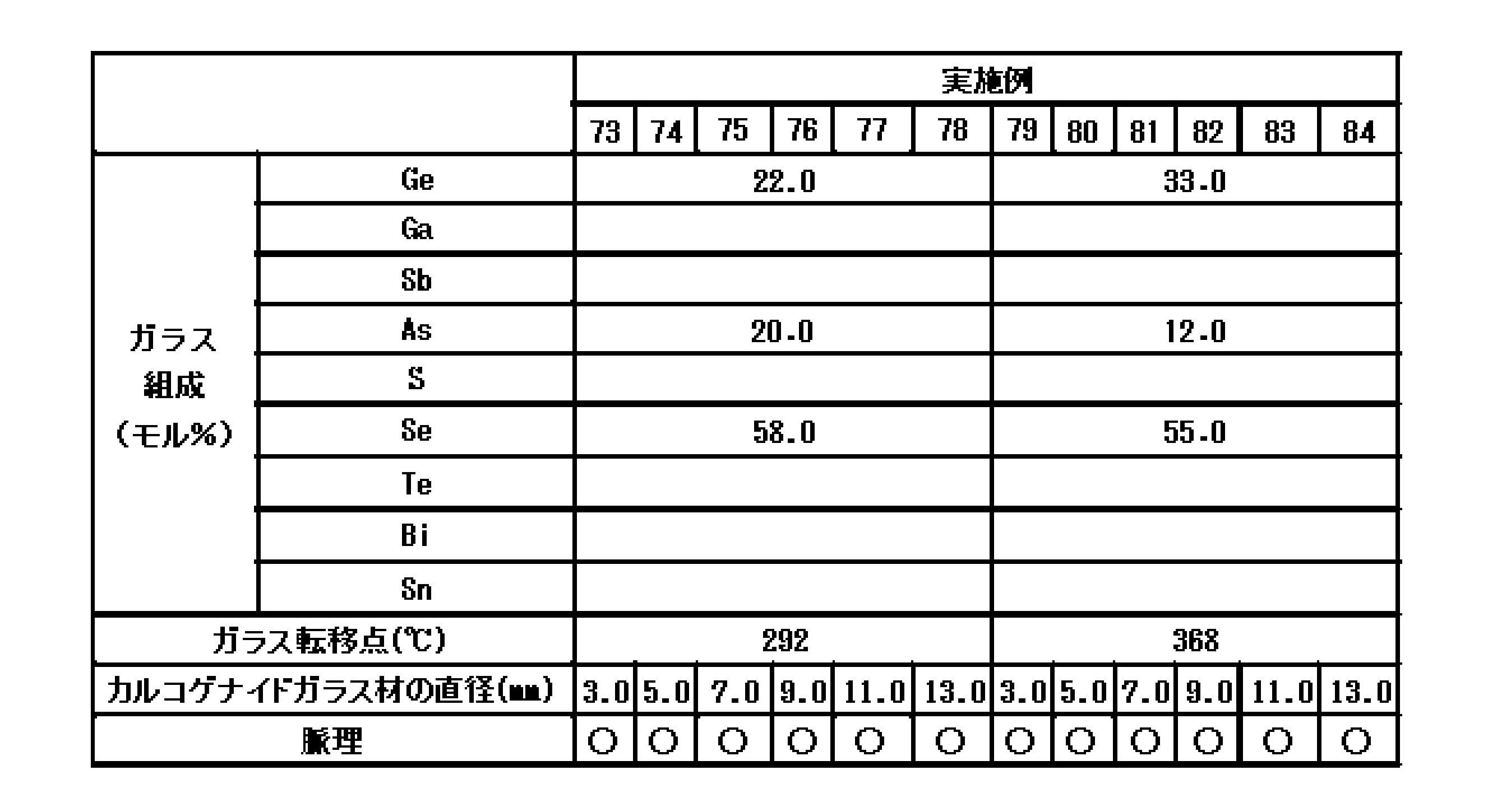
表1~16は、本発明の実施例1~180、比較例1、2を示している。


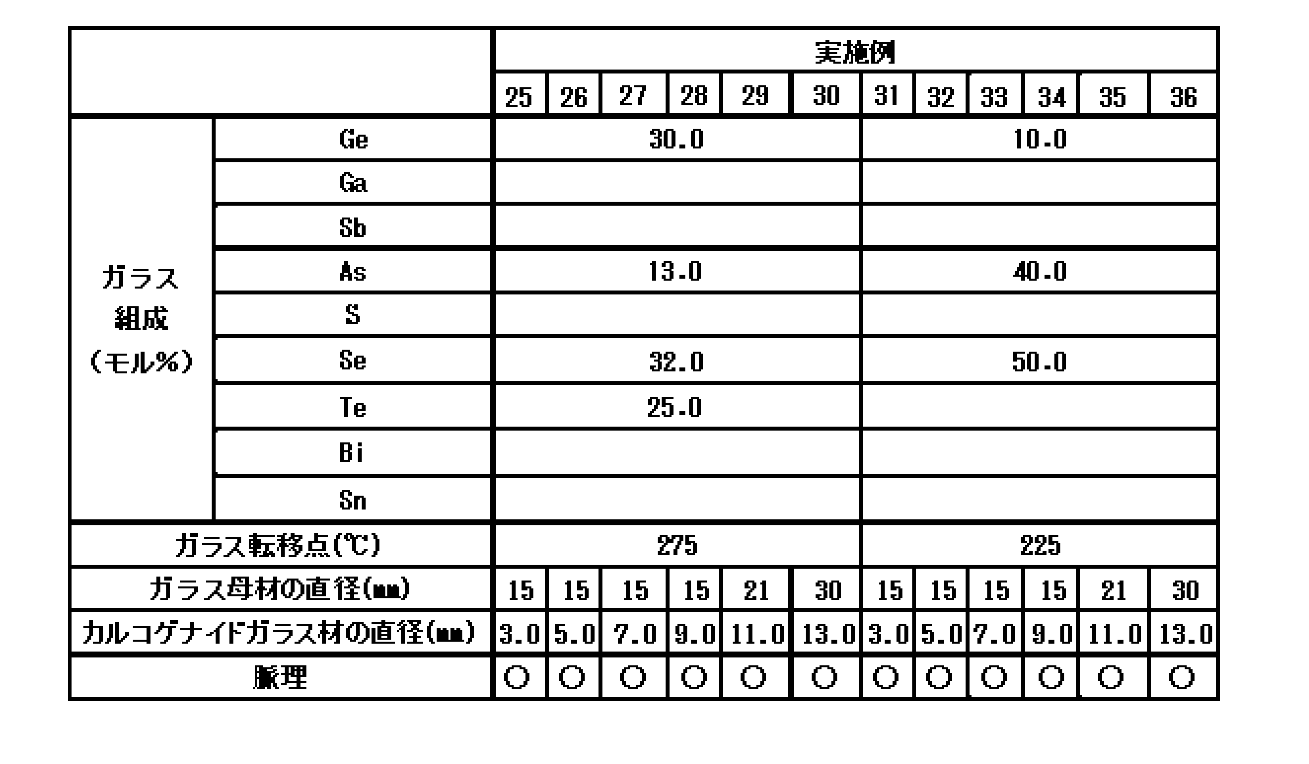

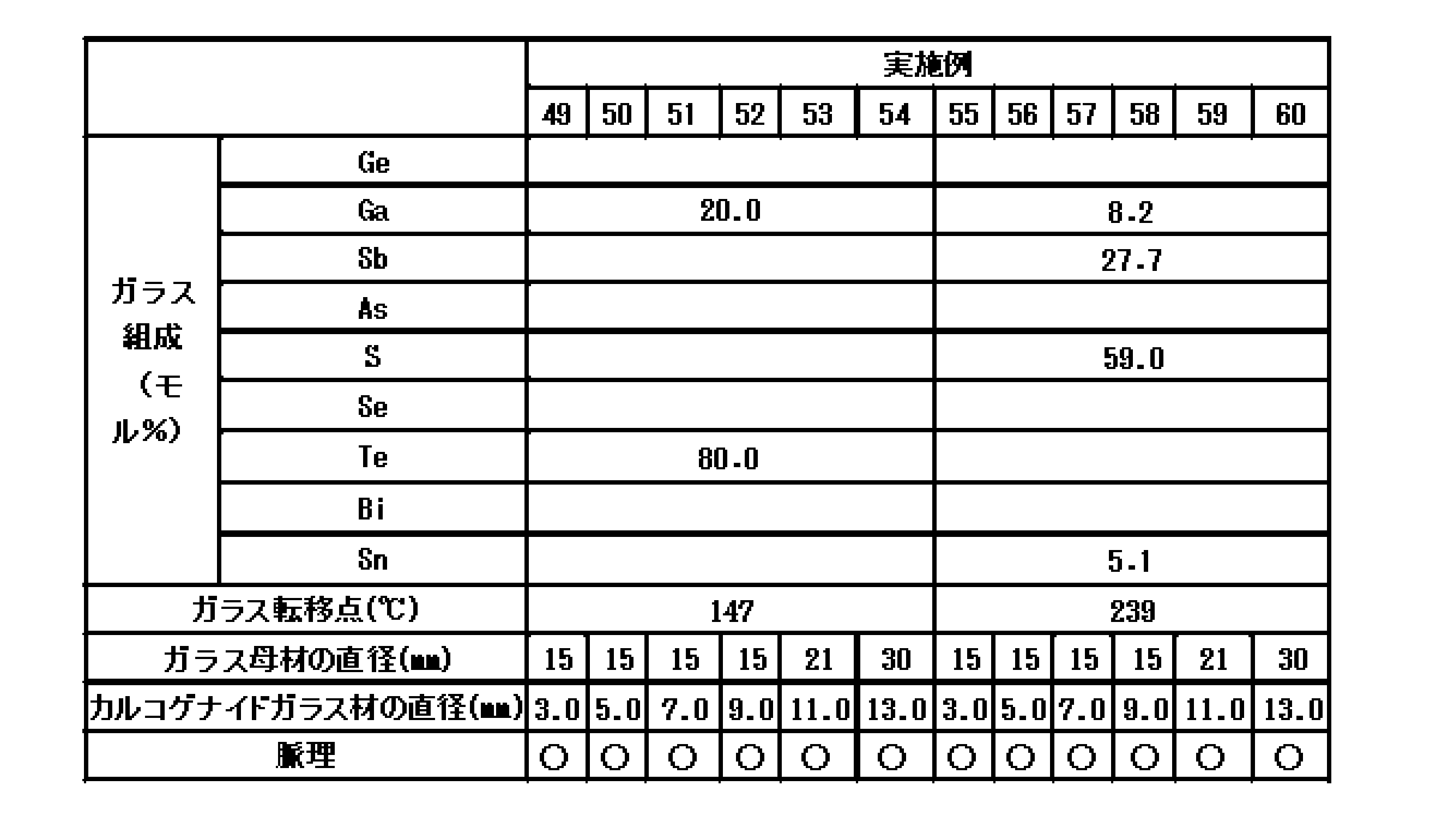


実施例1~60、比較例2の試料は次のようにして作製した。表に示す組成になるように原料を調合し、原料バッチを得た。次に、純水で洗浄した内径15~30mmの石英ガラスアンプルを加熱しながら真空排気した後、原料バッチを入れ、真空排気を行いながら酸素バーナーで石英ガラスアンプルを封管した。封管された石英ガラスアンプルを溶融炉内で10~20℃/時間の速度で650~1000℃まで昇温後、6~12時間保持した。保持時間中、2時間ごとに石英ガラスアンプルの上下を反転し、溶融物を攪拌した。その後、石英ガラスアンプルを溶融炉から取り出し、室温まで急冷することにより表に示す直径を有する円柱状のガラス母材を得た。
得られたガラス母材を窒素雰囲気下にて、ガラス転移点より30~50℃高い温度に加熱し、リドロー法により線引きすることで表に示す直径を有する円柱状のカルコゲナイドガラス材を得た。
実施例61~120の試料は以下のようにして作製した。表に示す組成になるように原料を調合し、原料バッチを得た。次に、純水で洗浄した内径15~50mmの石英ガラスアンプルを加熱しながら真空排気した後、原料バッチを入れ、真空排気を行いながら酸素バーナーで石英ガラスアンプルを封管した。封管された石英ガラスアンプルを溶融炉内で10~20℃/時間の速度で650~1000℃まで昇温後、6~12時間保持した。保持時間中、2時間ごとに石英ガラスアンプルの上下を反転し、溶融物を攪拌した。その後、石英ガラスアンプルを溶融炉から取り出し、窒素雰囲気下にて石英ガラスアンプルの一部を切断し、融液をカーボン製の鋳型に流し込み、室温まで急冷することにより表に示す直径を有する円柱状のカルコゲナイドガラス材を得た。
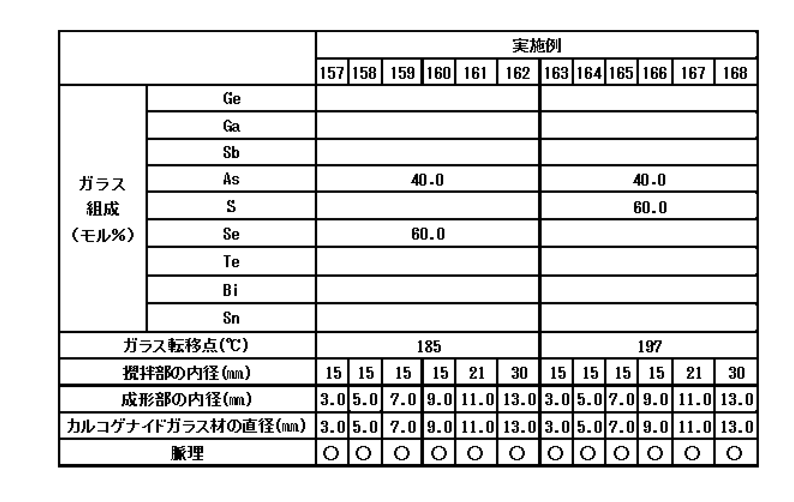
実施例121~180の試料は以下のようにして作製した。表に示す組成になるように原料を調合し、原料バッチを得た。次に、純水で洗浄した石英ガラスアンプルを加熱しながら真空排気した後、原料バッチを入れ、真空排気を行いながら酸素バーナーで石英ガラスアンプルを封管した。表に示す攪拌部の内径、及び、成形部の内径を有する封管された石英ガラスアンプルを溶融炉内で10~20℃/時間の速度で650~1000℃まで昇温後、6~12時間保持した。保持時間中、2時間ごとに石英ガラスアンプルの上下を反転し、溶融物を攪拌した。その後、石英ガラスアンプルを溶融炉から取り出し、融液を成形部に移動させ、室温まで急冷することにより表に示す直径を有する円柱状のカルコゲナイドガラス材を得た。
比較例1は以下のようにして作製した。表に示す組成になるように原料を調合し、原料バッチを得た。次に、純水で洗浄した内径5mmの石英ガラスアンプルを加熱しながら真空排気した後、原料バッチを入れ、真空排気を行いながら酸素バーナーで石英ガラスアンプルを封管した。封管された石英ガラスアンプルを溶融炉内で15℃/時間の速度で800℃まで昇温後、10時間保持した。保持時間中、2時間ごとに石英ガラスアンプルの上下を反転し、溶融物を攪拌した。その後、石英ガラスアンプルを溶融炉から取り出し、室温まで急冷することによりカルコゲナイドガラス材を得た。
得られた試料について、ガラス転移点、脈理を測定または評価した。
ガラス転移点は、TMA(熱機械分析装置)により測定した。
脈理は次のようにして評価した。得られた試料を波長1μmの赤外光を用いたシャドウグラフ法にて内部観察を行った。長さ500μm以上の脈理が観察されたものを「○」、500μm以上の脈理が観察されなかったものを「×」とした。図1に、実施例1の試料の内部を撮影した写真を示す。図2に、比較例1の試料の内部を撮影した写真を示す。
実施例1~180の試料は長さ500μm以上の脈理が観察されず、均質性に優れていた。また、未研磨であるため、耐候性、機械的強度に優れると考えられる。一方、比較例1、2は長さ500μm以上の脈理が観察され、均質性に劣っていた。
本発明のカルコゲナイドガラス材は、赤外線カメラの、赤外線センサ部に赤外光を集光させるためのレンズ等の光学素子として好適である。
Claims (9)
- 側面が未研磨で、直径15mm以下の柱状のカルコゲナイドガラス材であって、組成として、モル%で、S+Se+Te 40~90%を含有し、ガラス材中に長さ500μm以上の脈理が存在しないことを特徴とするカルコゲナイドガラス材。
- 側面が火造り面であることを特徴とする請求項1に記載のカルコゲナイドガラス材。
- モル%で、Ge+Ga+Sb+As 0超~50%を含有することを特徴とする請求項1又は2に記載のカルコゲナイドガラス材。
- モル%で、Ge+Ga 0~40%、Sb+As 0~45%を含有することを特徴とする請求項1~3のいずれかに記載のカルコゲナイドガラス材。
- モル%で、S+Se+Te 40~90%を含有するガラス母材をリドロー法により線引きすることを特徴とするカルコゲナイドガラス材の製造方法。
- 線引き温度が、(カルコゲナイドガラス材のガラス転移点+100℃)以下であることを特徴とする請求項5に記載のカルコゲナイドガラス材の製造方法。
- 真空雰囲気中または不活性雰囲気中で線引きすることを特徴とする請求項5または6に記載のカルコゲナイドガラス材の製造方法。
- 請求項1~4のいずれかに記載のカルコゲナイドガラス材を用いることを特徴とする光学素子。
- 請求項8に記載の光学素子を用いることを特徴とする赤外線センサ。
Priority Applications (4)
| Application Number | Priority Date | Filing Date | Title |
|---|---|---|---|
| US16/630,880 US20200148575A1 (en) | 2017-08-02 | 2018-06-28 | Chalcogenide glass material |
| CN201880050231.XA CN110997585A (zh) | 2017-08-02 | 2018-06-28 | 硫属化物玻璃材料 |
| EP18841572.3A EP3663267A4 (en) | 2017-08-02 | 2018-06-28 | CHALCOGENIDE GLASS MATERIAL |
| US17/528,224 US11760681B2 (en) | 2017-08-02 | 2021-11-17 | Chalcogenide glass material |
Applications Claiming Priority (2)
| Application Number | Priority Date | Filing Date | Title |
|---|---|---|---|
| JP2017-149788 | 2017-08-02 | ||
| JP2017149788A JP7070824B2 (ja) | 2017-08-02 | 2017-08-02 | カルコゲナイドガラス材 |
Related Child Applications (2)
| Application Number | Title | Priority Date | Filing Date |
|---|---|---|---|
| US16/630,880 A-371-Of-International US20200148575A1 (en) | 2017-08-02 | 2018-06-28 | Chalcogenide glass material |
| US17/528,224 Division US11760681B2 (en) | 2017-08-02 | 2021-11-17 | Chalcogenide glass material |
Publications (1)
| Publication Number | Publication Date |
|---|---|
| WO2019026489A1 true WO2019026489A1 (ja) | 2019-02-07 |
Family
ID=65232374
Family Applications (1)
| Application Number | Title | Priority Date | Filing Date |
|---|---|---|---|
| PCT/JP2018/024619 WO2019026489A1 (ja) | 2017-08-02 | 2018-06-28 | カルコゲナイドガラス材 |
Country Status (5)
| Country | Link |
|---|---|
| US (2) | US20200148575A1 (ja) |
| EP (1) | EP3663267A4 (ja) |
| JP (1) | JP7070824B2 (ja) |
| CN (1) | CN110997585A (ja) |
| WO (1) | WO2019026489A1 (ja) |
Families Citing this family (1)
| Publication number | Priority date | Publication date | Assignee | Title |
|---|---|---|---|---|
| CN112047627B (zh) * | 2020-08-14 | 2022-09-09 | 暨南大学 | 一种全谱段硫系玻璃材料及其制备方法 |
Citations (6)
| Publication number | Priority date | Publication date | Assignee | Title |
|---|---|---|---|---|
| JPH07291655A (ja) * | 1994-04-11 | 1995-11-07 | Corning Inc | 透明ガラス |
| JP2001354441A (ja) * | 2000-06-12 | 2001-12-25 | Nippon Sheet Glass Co Ltd | 光学ガラス素子の製造方法、及び該製造方法により製造された光学ガラス素子 |
| JP2003192362A (ja) * | 2001-12-25 | 2003-07-09 | Furukawa Co Ltd | カルコゲナイドガラスの製造方法 |
| JP2009161374A (ja) | 2007-12-28 | 2009-07-23 | Isuzu Seiko Glass Kk | モールド成型用赤外線透過ガラス |
| JP2015129072A (ja) * | 2014-01-09 | 2015-07-16 | 日本電気硝子株式会社 | 赤外線透過ガラス |
| WO2016184770A1 (fr) * | 2015-05-15 | 2016-11-24 | Centre National De La Recherche Scientifique (Cnrs) | Fibre optique ruban en verre photosensible |
Family Cites Families (21)
| Publication number | Priority date | Publication date | Assignee | Title |
|---|---|---|---|---|
| JPS61127639A (ja) * | 1984-11-21 | 1986-06-14 | Hitachi Ltd | 赤外光フアイバ用材料 |
| JPS6317231A (ja) * | 1986-07-03 | 1988-01-25 | Sumitomo Electric Ind Ltd | カルコゲナイドガラスフアイバ母材の製造方法及びその装置 |
| US5160521A (en) * | 1991-06-21 | 1992-11-03 | Tran Danh C | Method for making optical fiber preforms |
| US5346523A (en) * | 1992-03-31 | 1994-09-13 | Matsushita Electric Industrial Co., Ltd. | Method of molding chalcogenide glass lenses |
| JPH05330832A (ja) * | 1992-03-31 | 1993-12-14 | Matsushita Electric Ind Co Ltd | カルコゲナイドガラスレンズの成形方法 |
| US6015765A (en) * | 1997-12-24 | 2000-01-18 | The United States Of America As Represented By The Secretary Of The Navy | Rare earth soluble telluride glasses |
| US6405565B1 (en) * | 2000-11-01 | 2002-06-18 | Corning Incorporated | Chalcogenide glass tubing fabrication |
| CN1736917A (zh) * | 2005-08-08 | 2006-02-22 | 华东理工大学 | 一种含铅硫化物玻璃及其制备方法 |
| JP2009063942A (ja) * | 2007-09-10 | 2009-03-26 | Sumitomo Electric Ind Ltd | 遠赤外線カメラ用レンズ、レンズユニット及び撮像装置 |
| US20100022378A1 (en) * | 2008-07-25 | 2010-01-28 | Nguyen Vinh Q | Manufacturing process for chalcogenide glasses |
| US7693388B1 (en) * | 2008-09-15 | 2010-04-06 | The United States Of America As Represented By The Secretary Of The Navy | Thermally stable IR transmitting chalcogenide glass |
| US20110274924A1 (en) * | 2010-05-05 | 2011-11-10 | Advalue Photonics, Inc. | Mid-infrared transmitting fiber |
| CN101891386B (zh) * | 2010-07-05 | 2012-02-15 | 宁波大学 | 一种碲基硫系红外玻璃及其制备方法 |
| DE102014103560A1 (de) * | 2013-03-15 | 2014-09-18 | Schott Corporation | Optisches Binden durch die Verwendung von optischem Glas mit niedrigem Erweichungspunkt für optische IR-Anwendungen und gebildete Produkte |
| US9708210B2 (en) * | 2014-06-03 | 2017-07-18 | The United States Of America, As Represented By The Secretary Of The Navy | Striae-free chalcogenide glasses |
| CN104355538B (zh) * | 2014-10-20 | 2016-12-21 | 江苏师范大学 | 一种硫化物红外玻璃及制备方法 |
| US10131568B2 (en) * | 2015-03-03 | 2018-11-20 | The United States Of America, As Represented By The Secretary Of The Navy | Manufacturing process for striae-free multicomponent chalcogenide glasses via multiple fining steps |
| CN105110634B (zh) * | 2015-06-25 | 2017-07-28 | 中国科学院西安光学精密机械研究所 | 多孔红外硫系玻璃光纤的制备方法 |
| EP3378844B1 (en) * | 2015-11-20 | 2020-01-15 | AGC Inc. | Optical glass |
| US10450214B2 (en) * | 2016-06-10 | 2019-10-22 | Corning Incorporated | High optical quality glass tubing and method of making |
| WO2018112386A1 (en) * | 2016-12-16 | 2018-06-21 | Schott Corporation | Chalcogenide compositions for optical fibers and other systems |
-
2017
- 2017-08-02 JP JP2017149788A patent/JP7070824B2/ja active Active
-
2018
- 2018-06-28 EP EP18841572.3A patent/EP3663267A4/en active Pending
- 2018-06-28 CN CN201880050231.XA patent/CN110997585A/zh active Pending
- 2018-06-28 WO PCT/JP2018/024619 patent/WO2019026489A1/ja unknown
- 2018-06-28 US US16/630,880 patent/US20200148575A1/en not_active Abandoned
-
2021
- 2021-11-17 US US17/528,224 patent/US11760681B2/en active Active
Patent Citations (6)
| Publication number | Priority date | Publication date | Assignee | Title |
|---|---|---|---|---|
| JPH07291655A (ja) * | 1994-04-11 | 1995-11-07 | Corning Inc | 透明ガラス |
| JP2001354441A (ja) * | 2000-06-12 | 2001-12-25 | Nippon Sheet Glass Co Ltd | 光学ガラス素子の製造方法、及び該製造方法により製造された光学ガラス素子 |
| JP2003192362A (ja) * | 2001-12-25 | 2003-07-09 | Furukawa Co Ltd | カルコゲナイドガラスの製造方法 |
| JP2009161374A (ja) | 2007-12-28 | 2009-07-23 | Isuzu Seiko Glass Kk | モールド成型用赤外線透過ガラス |
| JP2015129072A (ja) * | 2014-01-09 | 2015-07-16 | 日本電気硝子株式会社 | 赤外線透過ガラス |
| WO2016184770A1 (fr) * | 2015-05-15 | 2016-11-24 | Centre National De La Recherche Scientifique (Cnrs) | Fibre optique ruban en verre photosensible |
Also Published As
| Publication number | Publication date |
|---|---|
| CN110997585A (zh) | 2020-04-10 |
| EP3663267A4 (en) | 2021-04-14 |
| JP2019026530A (ja) | 2019-02-21 |
| EP3663267A1 (en) | 2020-06-10 |
| US11760681B2 (en) | 2023-09-19 |
| US20200148575A1 (en) | 2020-05-14 |
| US20220073400A1 (en) | 2022-03-10 |
| JP7070824B2 (ja) | 2022-05-18 |
Similar Documents
| Publication | Publication Date | Title |
|---|---|---|
| JP5048159B2 (ja) | 近赤外線カットフィルタガラス | |
| TWI389867B (zh) | 非球面透鏡及其製造方法 | |
| WO2020105719A1 (ja) | カルコゲナイドガラスレンズ | |
| JP6869482B2 (ja) | 光学ガラス及びその製造方法 | |
| JP2018118900A (ja) | 光学ガラスレンズ | |
| JP2023059941A (ja) | カルコゲナイドガラス材 | |
| WO2016163270A1 (ja) | 近赤外線吸収ガラス | |
| WO2016129470A1 (ja) | 光学ガラス及びその製造方法 | |
| JP6075714B2 (ja) | 光学ガラス | |
| WO2019026489A1 (ja) | カルコゲナイドガラス材 | |
| WO2017208679A1 (ja) | 近赤外線吸収ガラスの製造方法及び製造装置 | |
| WO2019039202A1 (ja) | 近赤外線吸収ガラス | |
| WO2018155105A1 (ja) | 光学ガラス | |
| JP6869481B2 (ja) | 光学ガラス及びその製造方法 | |
| WO2015001944A1 (ja) | Irカットフィルタ用ガラス | |
| JP2007186407A (ja) | 光学ガラス | |
| JP2018140928A (ja) | 光学ガラス | |
| JP7290022B2 (ja) | カルコゲナイドガラス材 | |
| WO2018016149A1 (ja) | 赤外線透過性レンズの製造方法、赤外線透過性レンズ及び赤外線カメラ | |
| CN109195926B (zh) | 近红外线吸收玻璃的制造方法和制造装置 | |
| WO2019044324A1 (ja) | 近赤外線吸収ガラス | |
| JP2016199408A (ja) | 光学ガラス及びその製造方法 | |
| JP2007176748A (ja) | 光学ガラス | |
| JP2017178632A (ja) | 近赤外線吸収ガラス | |
| JP6660607B2 (ja) | 光学ガラス及びその製造方法 |
Legal Events
| Date | Code | Title | Description |
|---|---|---|---|
| 121 | Ep: the epo has been informed by wipo that ep was designated in this application |
Ref document number: 18841572 Country of ref document: EP Kind code of ref document: A1 |
|
| NENP | Non-entry into the national phase |
Ref country code: DE |
|
| ENP | Entry into the national phase |
Ref document number: 2018841572 Country of ref document: EP Effective date: 20200302 |