WO2019026468A1 - 防眩フィルム - Google Patents
防眩フィルム Download PDFInfo
- Publication number
- WO2019026468A1 WO2019026468A1 PCT/JP2018/023940 JP2018023940W WO2019026468A1 WO 2019026468 A1 WO2019026468 A1 WO 2019026468A1 JP 2018023940 W JP2018023940 W JP 2018023940W WO 2019026468 A1 WO2019026468 A1 WO 2019026468A1
- Authority
- WO
- WIPO (PCT)
- Prior art keywords
- antiglare
- resin
- film
- display
- antiglare layer
- Prior art date
- Legal status (The legal status is an assumption and is not a legal conclusion. Google has not performed a legal analysis and makes no representation as to the accuracy of the status listed.)
- Ceased
Links
Images


Classifications
-
- G—PHYSICS
- G02—OPTICS
- G02B—OPTICAL ELEMENTS, SYSTEMS OR APPARATUS
- G02B5/00—Optical elements other than lenses
- G02B5/02—Diffusing elements; Afocal elements
-
- G—PHYSICS
- G02—OPTICS
- G02B—OPTICAL ELEMENTS, SYSTEMS OR APPARATUS
- G02B5/00—Optical elements other than lenses
- G02B5/02—Diffusing elements; Afocal elements
- G02B5/0205—Diffusing elements; Afocal elements characterised by the diffusing properties
- G02B5/0236—Diffusing elements; Afocal elements characterised by the diffusing properties the diffusion taking place within the volume of the element
- G02B5/0242—Diffusing elements; Afocal elements characterised by the diffusing properties the diffusion taking place within the volume of the element by means of dispersed particles
-
- C—CHEMISTRY; METALLURGY
- C09—DYES; PAINTS; POLISHES; NATURAL RESINS; ADHESIVES; COMPOSITIONS NOT OTHERWISE PROVIDED FOR; APPLICATIONS OF MATERIALS NOT OTHERWISE PROVIDED FOR
- C09D—COATING COMPOSITIONS, e.g. PAINTS, VARNISHES OR LACQUERS; FILLING PASTES; CHEMICAL PAINT OR INK REMOVERS; INKS; CORRECTING FLUIDS; WOODSTAINS; PASTES OR SOLIDS FOR COLOURING OR PRINTING; USE OF MATERIALS THEREFOR
- C09D5/00—Coating compositions, e.g. paints, varnishes or lacquers, characterised by their physical nature or the effects produced; Filling pastes
- C09D5/006—Anti-reflective coatings
-
- B—PERFORMING OPERATIONS; TRANSPORTING
- B32—LAYERED PRODUCTS
- B32B—LAYERED PRODUCTS, i.e. PRODUCTS BUILT-UP OF STRATA OF FLAT OR NON-FLAT, e.g. CELLULAR OR HONEYCOMB, FORM
- B32B7/00—Layered products characterised by the relation between layers; Layered products characterised by the relative orientation of features between layers, or by the relative values of a measurable parameter between layers, i.e. products comprising layers having different physical, chemical or physicochemical properties; Layered products characterised by the interconnection of layers
- B32B7/02—Physical, chemical or physicochemical properties
-
- C—CHEMISTRY; METALLURGY
- C08—ORGANIC MACROMOLECULAR COMPOUNDS; THEIR PREPARATION OR CHEMICAL WORKING-UP; COMPOSITIONS BASED THEREON
- C08F—MACROMOLECULAR COMPOUNDS OBTAINED BY REACTIONS ONLY INVOLVING CARBON-TO-CARBON UNSATURATED BONDS
- C08F265/00—Macromolecular compounds obtained by polymerising monomers on to polymers of unsaturated monocarboxylic acids or derivatives thereof as defined in group C08F20/00
- C08F265/04—Macromolecular compounds obtained by polymerising monomers on to polymers of unsaturated monocarboxylic acids or derivatives thereof as defined in group C08F20/00 on to polymers of esters
- C08F265/06—Polymerisation of acrylate or methacrylate esters on to polymers thereof
-
- C—CHEMISTRY; METALLURGY
- C08—ORGANIC MACROMOLECULAR COMPOUNDS; THEIR PREPARATION OR CHEMICAL WORKING-UP; COMPOSITIONS BASED THEREON
- C08F—MACROMOLECULAR COMPOUNDS OBTAINED BY REACTIONS ONLY INVOLVING CARBON-TO-CARBON UNSATURATED BONDS
- C08F292/00—Macromolecular compounds obtained by polymerising monomers on to inorganic materials
-
- C—CHEMISTRY; METALLURGY
- C08—ORGANIC MACROMOLECULAR COMPOUNDS; THEIR PREPARATION OR CHEMICAL WORKING-UP; COMPOSITIONS BASED THEREON
- C08J—WORKING-UP; GENERAL PROCESSES OF COMPOUNDING; AFTER-TREATMENT NOT COVERED BY SUBCLASSES C08B, C08C, C08F, C08G or C08H
- C08J7/00—Chemical treatment or coating of shaped articles made of macromolecular substances
- C08J7/04—Coating
-
- C—CHEMISTRY; METALLURGY
- C08—ORGANIC MACROMOLECULAR COMPOUNDS; THEIR PREPARATION OR CHEMICAL WORKING-UP; COMPOSITIONS BASED THEREON
- C08J—WORKING-UP; GENERAL PROCESSES OF COMPOUNDING; AFTER-TREATMENT NOT COVERED BY SUBCLASSES C08B, C08C, C08F, C08G or C08H
- C08J7/00—Chemical treatment or coating of shaped articles made of macromolecular substances
- C08J7/04—Coating
- C08J7/043—Improving the adhesiveness of the coatings per se, e.g. forming primers
-
- C—CHEMISTRY; METALLURGY
- C08—ORGANIC MACROMOLECULAR COMPOUNDS; THEIR PREPARATION OR CHEMICAL WORKING-UP; COMPOSITIONS BASED THEREON
- C08J—WORKING-UP; GENERAL PROCESSES OF COMPOUNDING; AFTER-TREATMENT NOT COVERED BY SUBCLASSES C08B, C08C, C08F, C08G or C08H
- C08J7/00—Chemical treatment or coating of shaped articles made of macromolecular substances
- C08J7/04—Coating
- C08J7/046—Forming abrasion-resistant coatings; Forming surface-hardening coatings
-
- C—CHEMISTRY; METALLURGY
- C08—ORGANIC MACROMOLECULAR COMPOUNDS; THEIR PREPARATION OR CHEMICAL WORKING-UP; COMPOSITIONS BASED THEREON
- C08J—WORKING-UP; GENERAL PROCESSES OF COMPOUNDING; AFTER-TREATMENT NOT COVERED BY SUBCLASSES C08B, C08C, C08F, C08G or C08H
- C08J7/00—Chemical treatment or coating of shaped articles made of macromolecular substances
- C08J7/12—Chemical modification
- C08J7/16—Chemical modification with polymerisable compounds
- C08J7/18—Chemical modification with polymerisable compounds using wave energy or particle radiation
-
- C—CHEMISTRY; METALLURGY
- C09—DYES; PAINTS; POLISHES; NATURAL RESINS; ADHESIVES; COMPOSITIONS NOT OTHERWISE PROVIDED FOR; APPLICATIONS OF MATERIALS NOT OTHERWISE PROVIDED FOR
- C09D—COATING COMPOSITIONS, e.g. PAINTS, VARNISHES OR LACQUERS; FILLING PASTES; CHEMICAL PAINT OR INK REMOVERS; INKS; CORRECTING FLUIDS; WOODSTAINS; PASTES OR SOLIDS FOR COLOURING OR PRINTING; USE OF MATERIALS THEREFOR
- C09D133/00—Coating compositions based on homopolymers or copolymers of compounds having one or more unsaturated aliphatic radicals, each having only one carbon-to-carbon double bond, and at least one being terminated by only one carboxyl radical, or of salts, anhydrides, esters, amides, imides, or nitriles thereof; Coating compositions based on derivatives of such polymers
- C09D133/04—Homopolymers or copolymers of esters
- C09D133/06—Homopolymers or copolymers of esters of esters containing only carbon, hydrogen and oxygen, the oxygen atom being present only as part of the carboxyl radical
- C09D133/08—Homopolymers or copolymers of acrylic acid esters
-
- C—CHEMISTRY; METALLURGY
- C09—DYES; PAINTS; POLISHES; NATURAL RESINS; ADHESIVES; COMPOSITIONS NOT OTHERWISE PROVIDED FOR; APPLICATIONS OF MATERIALS NOT OTHERWISE PROVIDED FOR
- C09D—COATING COMPOSITIONS, e.g. PAINTS, VARNISHES OR LACQUERS; FILLING PASTES; CHEMICAL PAINT OR INK REMOVERS; INKS; CORRECTING FLUIDS; WOODSTAINS; PASTES OR SOLIDS FOR COLOURING OR PRINTING; USE OF MATERIALS THEREFOR
- C09D4/00—Coating compositions, e.g. paints, varnishes or lacquers, based on organic non-macromolecular compounds having at least one polymerisable carbon-to-carbon unsaturated bond ; Coating compositions, based on monomers of macromolecular compounds of groups C09D183/00 - C09D183/16
- C09D4/06—Organic non-macromolecular compounds having at least one polymerisable carbon-to-carbon unsaturated bond in combination with a macromolecular compound other than an unsaturated polymer of groups C09D159/00 - C09D187/00
-
- G—PHYSICS
- G02—OPTICS
- G02B—OPTICAL ELEMENTS, SYSTEMS OR APPARATUS
- G02B5/00—Optical elements other than lenses
- G02B5/02—Diffusing elements; Afocal elements
- G02B5/0205—Diffusing elements; Afocal elements characterised by the diffusing properties
- G02B5/021—Diffusing elements; Afocal elements characterised by the diffusing properties the diffusion taking place at the element's surface, e.g. by means of surface roughening or microprismatic structures
-
- G—PHYSICS
- G02—OPTICS
- G02B—OPTICAL ELEMENTS, SYSTEMS OR APPARATUS
- G02B5/00—Optical elements other than lenses
- G02B5/02—Diffusing elements; Afocal elements
- G02B5/0268—Diffusing elements; Afocal elements characterized by the fabrication or manufacturing method
-
- G—PHYSICS
- G02—OPTICS
- G02B—OPTICAL ELEMENTS, SYSTEMS OR APPARATUS
- G02B5/00—Optical elements other than lenses
- G02B5/02—Diffusing elements; Afocal elements
- G02B5/0273—Diffusing elements; Afocal elements characterized by the use
- G02B5/0278—Diffusing elements; Afocal elements characterized by the use used in transmission
-
- G—PHYSICS
- G09—EDUCATION; CRYPTOGRAPHY; DISPLAY; ADVERTISING; SEALS
- G09F—DISPLAYING; ADVERTISING; SIGNS; LABELS OR NAME-PLATES; SEALS
- G09F9/00—Indicating arrangements for variable information in which the information is built-up on a support by selection or combination of individual elements
-
- C—CHEMISTRY; METALLURGY
- C08—ORGANIC MACROMOLECULAR COMPOUNDS; THEIR PREPARATION OR CHEMICAL WORKING-UP; COMPOSITIONS BASED THEREON
- C08F—MACROMOLECULAR COMPOUNDS OBTAINED BY REACTIONS ONLY INVOLVING CARBON-TO-CARBON UNSATURATED BONDS
- C08F2/00—Processes of polymerisation
- C08F2/46—Polymerisation initiated by wave energy or particle radiation
- C08F2/48—Polymerisation initiated by wave energy or particle radiation by ultraviolet or visible light
- C08F2/50—Polymerisation initiated by wave energy or particle radiation by ultraviolet or visible light with sensitising agents
Definitions
- the present invention relates to an antiglare film that prevents the reflection of external light on the surface of a display.
- the antiglare film is, for example, a film having an antiglare layer having irregularities formed on its surface by roughening, which is attached to the surface of the display, scatters external light, and reflects external light onto the surface of the display. To prevent.
- a method of forming unevenness on the surface of the antiglare layer for example, as disclosed in Patent Document 1, a method of dispersing fine particles (filler) in the antiglare layer, as disclosed in Patent Document 2, Examples of the method include a method of utilizing a phase separation structure formed by spinodal decomposition from a liquid phase of a plurality of polymers, and a method of transfer-molding a concavo-convex shape with a mold as disclosed in Patent Document 3.
- the antiglare film When the antiglare film is mounted on the surface of the display, reflection of external light on the surface of the display is prevented, while the light from the display is affected by the antiglare film, and the display performance of the display via the antiglare film May decrease. For this reason, it is desirable that the design freedom of the transmitted image definition of the antiglare film is high.
- an antiglare film is mounted on the surface of a display having high definition pixels
- light from the display transmitting the antiglare film is refracted due to the unevenness of the surface of the antiglare layer, or due to the unevenness of the surface of the antiglare layer
- the display may flicker and the image may be difficult to view.
- the glare of a display has a surface which is difficult to evaluate quantitatively, and it may be difficult to develop the anti-glare film which can suppress the glare of a display effectively according to an objective parameter
- the present invention can suppress glare of the display while having good antiglare properties by quantitatively evaluating and designing the glare of the display, and also an antiglare having design freedom of high transmitted image definition.
- the purpose is to provide a film.
- one mode of the present invention is provided with the glare-proof layer whose haze value is a value of 50% or more and 99% or less of value, and is attached to the surface of a display.
- the standard deviation is a value in the range of 0 to 6
- the transmission image definition of the optical comb width 0.5 mm is a value in the range of 0% to 60%.
- the value of the standard deviation of the luminance distribution of the display indicates the degree of variation of the bright spots on the display, and serves as an objective index that can quantitatively evaluate the glare of the display. Therefore, in the above configuration, the glare of the display can be quantitatively evaluated to design the antiglare film by configuring the antiglare layer by setting the standard deviation to a value in the range of 0 or more and 6 or less. Therefore, for example, an antiglare film capable of effectively suppressing the glare of the display can be stably obtained as compared with the case where the tester subjectively evaluates the glare visually and the like.
- the standard deviation to a predetermined value and setting the haze value of the antiglare layer to a value in the range of 50% to 99%, good glare resistance can be achieved while suppressing glare on the display. You can get it.
- the transmission image clarity of the optical comb width 0.5 mm of the antiglare film to a value in the range of 0% to 60%, the design freedom of the transmission image definition of the antiglare film can be widely secured. .
- the antiglare layer may include a plurality of resin components, and may have a co-continuous phase structure formed by phase separation of the plurality of resin components.
- a bicontinuous phase structure By using such a bicontinuous phase structure, it is possible to easily obtain good antiglare properties while suppressing glare on the display.
- the antiglare layer may contain an acrylic copolymer, cellulose acetate propionate, and at least one of a nanosilica-containing acrylic ultraviolet curable compound and a urethane acrylate.
- the antiglare layer contains a matrix resin and a plurality of particles dispersed in the matrix resin, and the difference in refractive index between the particles and the matrix resin is in the range of 0 or more and 0.07 or less Good.
- the antiglare layer can be configured using a matrix resin and a plurality of fine particles, and the antiglare film having the antiglare property can be easily manufactured while suppressing the glare of the display.
- the ratio G2 / G1 of the weight G1 of the matrix resin of the antiglare layer to the total weight G2 of the plurality of fine particles contained in the antiglare layer is a value in the range of 0.07 to 0.20. May be Thereby, thereby, the said glare-proof film which has a glare-proof layer of the structure where some microparticles
- a glare film can be provided.
- FIG. 1 is a cross-sectional view showing the configuration of the antiglare film 1 according to the first embodiment.
- the antiglare film 1 is mounted on the surface of the display 16a of the display 16 (see FIG. 3).
- the antiglare film 1 includes a base film 2, an antiglare layer 3, and an adhesive layer 4.
- the base film 2 is disposed between the display 16 a and the antiglare layer 3 and supports the antiglare layer 3.
- the adhesive layer 4 is disposed between the display 16a and the base film 2, and fixes the antiglare film 1 to the surface of the display 16a.
- the adhesive layer 4 is, for example, an optical glue and is made of a material that hardly affects the optical characteristics of the antiglare film 1.
- the antiglare layer 3 is formed on at least one surface of the base film 2.
- the antiglare layer 3 imparts antiglare properties to the antiglare film 1, scatters and reflects external light, and prevents external light from reflecting on the surface of the display 16a.
- the antiglare layer 3 also functions as a hard coat (HC) layer that protects the surface of the display 16a.
- the antiglare layer 3 contains, as an example, a plurality of resin components capable of phase separation.
- the standard deviation of the luminance distribution of the display 16a in a state of being attached to the surface of the display 16a is set to a value in the range of 0 to 6 and a transmitted image definition of an optical comb width of 0.5 mm It is set to a value in the range of 0% to 60%.
- the antiglare layer 3 is set to have a haze value in the range of 50% to 99%.
- the haze value shown in the present embodiment is a value measured by a method in accordance with JIS K7136.
- the value of the standard deviation can be appropriately set within the above range, but is more preferably in the range of 0 or more and 5.5 or less, and more preferably in the range of 0 or more and 5.0 or less desirable.
- the value of the transmitted image definition (imageability) with an optical comb width of 0.5 mm can also be set appropriately within the above range, but it is more preferable that the value is in the range of 0% to 55%. It is more desirable that the value be in the range of% to 50%.
- the haze value of the antiglare layer 3 can be appropriately set in the above range, but is more preferably in the range of 50% to 90%, and is in the range of 50% to 85%. Is more desirable.
- the value of the standard deviation of the luminance distribution of the display 16a indicates the degree of the variation of the bright spots on the display 16a, and becomes an objective index that can quantitatively evaluate the glare of the display 16a. Based on this, by configuring the antiglare film 1 so that the standard deviation is set to a value in the range of 0 to 6, the glare of the display 16a can be quantitatively evaluated to design the antiglare film 1.
- the glare-proof film 1 capable of effectively suppressing the glare of the display 16a can be stably obtained as compared with the case where the tester subjectively evaluates the glare of the display 16a visually.
- the design freedom of the transmission image definition of the antiglare film 1 is broad. Can be secured.
- the antiglare layer 3 of the present embodiment includes a plurality of resin components, and has a co-continuous phase structure formed by phase separation of the plurality of resin components.
- the antiglare film 1 can easily obtain good antiglare properties while suppressing glare of the display 16a.
- the antiglare layer 3 of the present embodiment contains an acrylic copolymer, cellulose acetate propionate, and at least one of the nanosilica-containing acrylic ultraviolet curable compound and the urethane acrylate (both here). .
- the antiglare film 1 having the antiglare property while suppressing glare of the display 16a.
- specific examples of the base film 2 and the antiglare layer 3 will be described.
- the base film 2 glass, ceramics, and resin can be illustrated.
- the resin the same resin as the material of the antiglare layer 3 can be used.
- Preferred materials for the base film 2 include transparent polymers such as cellulose derivatives (cellulose triacetate (TAC), cellulose acetate such as cellulose diacetate, etc.), polyester resins (polyethylene terephthalate (PET), polyethylene naphthalate (PEN) ), Polybutylene terephthalate (PBT), polyarylate resin etc.), polysulfone resin (polysulfone, polyethersulfone (PES) etc.), polyether ketone resin (polyether ketone (PEK), polyether ether ketone (PEEK) Etc.), polycarbonate-based resin (PC), polyolefin-based resin (polyethylene, polypropylene etc.), cyclic polyolefin-based resin (JSR Corporation film “ARTON” (registered trademark) ) Nippon Zeon Co
- product film “ZEONEX (registered trademark)”, halogen-containing resin (polyvinylidene chloride etc.), (meth) acrylic resin, styrene resin (polystyrene etc), vinyl acetate or A vinyl alcohol resin (polyvinyl alcohol etc.) can be illustrated.
- the base film 2 may be uniaxially or biaxially stretched, but is preferably optically isotropic and has a low refractive index.
- an unstretched film can be illustrated.
- the thickness dimension of the base film 2 can be set appropriately, for example, it is preferably a value in the range of 5 ⁇ m to 2000 ⁇ m, more preferably in the range of 15 ⁇ m to 1000 ⁇ m, and in the range of 20 ⁇ m to 500 ⁇ m. It is more desirable that the value of
- the antiglare layer 3 of the first embodiment has a phase separation structure of a plurality of resin components.
- the glare-proof layer 3 has a plurality of elongated (string-like or linear) convex portions formed on the surface, for example, by phase separation structure of a plurality of resin components.
- the elongated projections are branched to form a bicontinuous phase structure in a dense state.
- the antiglare layer 3 exhibits antiglare property by the plurality of elongated projections and the concave portion positioned between the adjacent elongated projections.
- the antiglare film 1 is excellent in the balance between the haze value and the transmitted image sharpness (imageability).
- the surface of the antiglare layer 3 has a network-like structure, in other words, a plurality of continuous or partially omitted irregular loop structures, by forming the long and thin convex portions in a substantially network shape.
- the surface of the antiglare layer 3 is prevented from forming a lens-like (sea-island-like) convex portion by forming the above-described structure. Therefore, the light from the display 16a transmitted through the antiglare layer 3 is refracted by the unevenness of the surface of the antiglare layer 3, or the pixel of the display 16a is enlarged and seen by the lens effect due to the unevenness of the surface of the antiglare layer 3 This is prevented and the glare of the display 16a is suppressed.
- the antiglare film 1 is attached to the display 16a having high definition pixels, glare of the display 16a can be highly suppressed while securing the antiglare property, and blurring of characters and images and changes in color tone can also be suppressed. .
- the plurality of elongated projections may be independent of one another or connected to one another.
- the phase separation structure of the antiglare layer 3 is formed by spinodal decomposition (wet spinodal decomposition) from a liquid phase using a solution serving as a raw material of the antiglare layer 3 as described later.
- spinodal decomposition wet spinodal decomposition
- the plurality of resin components contained in the antiglare layer 3 may be those which can be phase separated, but from the viewpoint of obtaining the antiglare layer 3 having long thin convex portions and high scratch resistance, the polymer and the curing It is preferable to contain a hydrophobic resin.
- thermoplastic resin As a polymer which the glare-proof layer 3 contains, a thermoplastic resin can be illustrated.
- a thermoplastic resin styrene resin, (meth) acrylic resin, organic acid vinyl ester resin, vinyl ether resin, halogen containing resin, olefin resin (including alicyclic olefin resin), polycarbonate resin, Polyester resin, polyamide resin, thermoplastic polyurethane resin, polysulfone resin (polyether sulfone, polysulfone, etc.), polyphenylene ether resin (polymer of 2,6-xylenol, etc.), cellulose derivative (cellulose esters, cellulose carbamate , Cellulose ethers, etc., silicone resin (polydimethylsiloxane, polymethylphenylsiloxane, etc.), rubber or elastomer (polybutadiene, diene rubber such as polyisoprene, styrene-butadiene copolymer
- polymer what has a functional group which participates in hardening reaction, or a functional group which reacts with a curable compound can also be illustrated.
- the polymer may have a functional group in the main chain or side chain.
- a condensable group or a reactive group for example, a hydroxyl group, an acid anhydride group, a carboxyl group, an amino group or an imino group, an epoxy group, a glycidyl group, an isocyanate group etc.
- a polymerizable group for example, C 2-6 alkenyl group such as vinyl, propenyl, isopropenyl, butenyl and allyl group, C 2-6 alkynyl group such as ethynyl, propynyl and butynyl group, C 2-6 alkenylidene group such as vinylidene group, or polymerization of these Examples thereof include groups having a sexual group (such as (meth) acryloyl group etc.) and the like. Of these functional groups, polymerizable groups are preferred.
- the antiglare layer 3 may contain plural types of polymers. Each of these polymers may be phase-separable by spinodal decomposition from the liquid phase, or may be mutually incompatible.
- the combination of the first polymer and the second polymer contained in the plurality of types of polymers is not particularly limited, but those incompatible with each other at the processing temperature can be used.
- the first polymer is a styrene resin (polystyrene, styrene-acrylonitrile copolymer, etc.)
- cellulose derivatives eg, cellulose esters such as cellulose acetate propionate
- Meta acrylic resin
- acrylic resin polymethyl methacrylate etc.
- alicyclic olefin resin polymer with norbornene as monomer
- polycarbonate resin polyester resin (poly C 2-4 alkylene arylate copolyester Etc.
- the first polymer is a cellulose derivative (for example, cellulose esters such as cellulose acetate propionate), as the second polymer, a styrene resin (polystyrene, styrene-acrylonitrile copolymer, etc.),
- a styrene resin polystyrene, styrene-acrylonitrile copolymer, etc.
- acrylic resins alicyclic olefin resins (polymers having norbornene as a monomer, etc.), polycarbonate resins, polyester resins (polyC 2-4 alkylene arylate copolyesters, etc.), etc. .
- cellulose esters for example, cellulose C 2-4 alkyl carboxylic acid esters such as cellulose diacetate, cellulose triacetate, cellulose acetate propionate, and cellulose acetate butyrate
- cellulose esters for example, cellulose C 2-4 alkyl carboxylic acid esters such as cellulose diacetate, cellulose triacetate, cellulose acetate propionate, and cellulose acetate butyrate
- the precursor of a curable resin contained in a plurality of resin components at the time of production of the antiglare layer 3 is active energy ray (ultraviolet ray or electron beam etc.), heat, etc. It is fixed by hardening by. Moreover, abrasion resistance and durability are imparted to the antiglare layer 3 by such a curable resin.
- At least one polymer contained in the plurality of types of polymers is a polymer having a functional group capable of reacting with the curable resin precursor in a side chain.
- the polymer forming the phase separation structure may include a thermoplastic resin and other polymers in addition to the two polymers incompatible with each other.
- the weight ratio M1 / M2 of the weight M1 of the first polymer to the weight M2 of the second polymer, and the glass transition temperature of the polymer can be set appropriately.
- the curable resin precursor has a functional group that reacts with active energy rays (such as ultraviolet light or electron beam) or heat, and is cured or crosslinked by this functional group to form a resin (in particular, a cured resin or a crosslinked resin).
- active energy rays such as ultraviolet light or electron beam
- heat a functional group that reacts with active energy rays (such as ultraviolet light or electron beam) or heat
- heat a functional group that reacts with active energy rays (such as ultraviolet light or electron beam) or heat
- a resin in particular, a cured resin or a crosslinked resin.
- the curable compound can be illustrated.
- thermosetting compounds or thermosetting resins epoxy groups, polymerizable groups, isocyanate groups, alkoxysilyl groups, silanol groups, etc.
- low molecular weight compounds eg, epoxy resins, unsaturated polyester resins
- photocurable (ionizing radiation curable) compounds ultraviolet curable compounds such as photocurable monomers, oligomers, etc.
- the photocurable compound As a preferable curable resin precursor, a photocurable compound which is cured in a short time by an ultraviolet ray, an electron beam or the like can be exemplified. Of these, UV curable compounds are particularly practical.
- the photocurable compound preferably has two or more (preferably about 2 to 15, more preferably about 4 to 10) polymerizable unsaturated bonds in the molecule.
- the photocurable compound is epoxy (meth) acrylate, urethane (meth) acrylate, polyester (meth) acrylate, silicone (meth) acrylate, a polyfunctional monomer having at least two polymerizable unsaturated bonds. Is preferred.
- the curable resin precursor may contain a curing agent according to the type.
- the thermosetting resin precursor may contain a curing agent such as amines or polyvalent carboxylic acids
- the photocurable resin precursor may contain a photopolymerization initiator.
- the photopolymerization initiator include conventional components such as acetophenones or propiophenones, benzyls, benzoins, benzophenones, thioxanthones, and acyl phosphine oxides.
- the curable resin precursor may contain a curing accelerator.
- the photocurable resin precursor may contain a photocurable accelerator, such as tertiary amines (such as dialkylaminobenzoic acid esters), a phosphine photopolymerization accelerator, and the like.
- phase separation for example, (a) a combination in which a plurality of polymers are mutually incompatible and phase separated, (b) a combination in which a polymer and a curable resin precursor are incompatible and phase separated, or And (c) combinations in which a plurality of curable resin precursors are phase-separated to be incompatible with each other.
- the refractive index of the polymer and the cured resin or cross-linked resin produced by curing of the curable resin precursor are different from each other.
- the refractive indices of a plurality of types of polymers are also different from each other.
- the refractive index difference between the polymer and the cured resin or cross-linked resin, and the refractive index difference between the plurality of polymers (the first polymer and the second polymer) are, for example, in the range of 0 or more and 0.04 or less It is desirable that the value be in the range of 0 or more and 0.02 or less.
- the antiglare layer 3 may contain a plurality of fine particles (fillers) dispersed in a matrix resin.
- the fine particles may be either organic fine particles or inorganic fine particles, and the plurality of fine particles may contain plural types of fine particles.
- the organic fine particles include crosslinked acrylic particles and crosslinked styrene particles.
- silica particles and alumina particles can be exemplified.
- the refractive index difference between the fine particles contained in the antiglare layer 3 and the matrix resin can be set, for example, to a value in the range of 0 or more and 0.20 or less.
- the refractive index difference is more preferably in the range of 0 or more and 0.15 or less, and more preferably in the range of 0 or more and 0.07 or less.
- the average particle diameter of the fine particles is not particularly limited, and can be set to, for example, a value in the range of 0.5 ⁇ m to 5.0 ⁇ m.
- the average particle diameter is more preferably in the range of 0.5 ⁇ m to 3.0 ⁇ m, and more preferably in the range of 0.5 ⁇ m to 2.0 ⁇ m.
- the average particle diameter said here is 50% volume average particle diameter in a Coulter-counter method (the average particle diameter referred to below is also made the same.).
- the fine particles may be solid or hollow. If the mean particle size of the fine particles is too small, antiglare properties are difficult to obtain, and if too large, the glaring of the display may increase.
- the thickness dimension of the antiglare layer 3 can be set as appropriate, but is preferably, for example, a value in the range of 0.3 ⁇ m to 20 ⁇ m, more preferably in the range of 1 ⁇ m to 15 ⁇ m, and 1 ⁇ m. It is more desirable that the value be in the range of 10 ⁇ m or more. Usually, it can be set to a value in the range of 2 ⁇ m to 10 ⁇ m (in particular, a value in the range of 3 ⁇ m to 7 ⁇ m).
- the thickness dimension of the glare-proof layer 3 in this case has a desirable value of the range of 1 micrometer or more and 100 micrometers or less, for example, 3 micrometers or more and 50 micrometers or less It is more desirable that the value is in the range.
- additives for example, organic or inorganic particles, stabilizers (antioxidants, ultraviolet absorbers, etc.), surfactants, water-soluble polymers, and fillers are used insofar as the optical properties are not impaired.
- An agent, a crosslinking agent, a coupling agent, a coloring agent, a flame retardant, a lubricant, a wax, a preservative, a viscosity modifier, a thickener, a leveling agent, an antifoaming agent, etc. may be contained.
- the method for producing the antiglare film 1 in the first embodiment includes, as an example, a preparation step of preparing a solution (hereinafter, also simply referred to as a solution) to be a raw material of the antiglare layer 3 and a solution prepared in the preparation step. And forming a phase separation structure by spinodal decomposition from a liquid phase, and curing the solution after forming the phase separation structure. And curing the resin precursor.
- a solution hereinafter, also simply referred to as a solution
- a solution containing a solvent, a resin composition for constituting the antiglare layer 3 and predetermined fine particles is prepared.
- the solvent can be selected according to the type and solubility of the polymer and the curable resin precursor contained in the antiglare layer 3 described above.
- the solvent may be any solvent as long as it can uniformly dissolve at least solid content (a plurality of types of polymers and curable resin precursors, reaction initiators, and other additives).
- ketones acetone, methyl ethyl ketone, methyl isobutyl ketone, cyclohexanone etc.
- ethers dioxane, tetrahydrofuran etc.
- aliphatic hydrocarbons hexane etc.
- alicyclic hydrocarbons cyclohexane etc.
- Aromatic hydrocarbons toluene, xylene etc.
- halogenated carbons diichloromethane, dichloroethane etc.
- esters methyl acetate, ethyl acetate, butyl acetate etc.
- water alcohols
- alcohols ethanol, isopropanol, butanol, cyclo
- examples include hexanol and the like, cellosolves (such as methyl cellosolve and ethyl cellosolve), cellosolve acetates, sulfoxides (such as dimethylsulfoxide), and amide
- the composition containing the said thermoplastic resin, a photocurable compound, a photoinitiator, the said thermoplastic resin, and a photocurable compound is desirable.
- a composition containing the plurality of mutually incompatible polymers, a photocurable compound, and a photopolymerization initiator is desirable.
- the concentration of the solute (polymer and curable resin precursor, reaction initiator, other additives) in the solution is a range in which phase separation of a plurality of resin components occurs, and a range that does not impair the castability, coatability, etc. of the solution. Can be adjusted.
- the haze value of the antiglare layer 3, the transmitted image definition of the antiglare film 1, and the value (glare value) of the standard deviation of the luminance distribution of the display 16a having the antiglare film 1 mounted on the surface are in the solution. It may be changed depending on the combination and weight ratio of the resin composition of the above, or the application conditions of the preparation step, the formation step, and the curing step. Therefore, each condition is changed to form an antiglare layer, and the physical properties of the obtained antiglare layer are measured and grasped in advance, whereby an antiglare film having the desired physical properties can be obtained.
- the solution prepared in the preparation step is cast or applied onto the surface of the support (here, the base film 2 as an example).
- the solution casting method or coating method may be a conventional method, for example, spray, spinner, roll coater, air knife coater, blade coater, rod coater, reverse coater, bar coater, comma coater, dip, dip squeeze coater, Daiko It is possible to exemplify a tar, a gravure coater, a microgravure coater, a silk screen coater and the like.
- the solvent is removed by evaporation by drying from the solution cast or applied onto the surface of the support.
- phase separation by spinodal decomposition from the liquid phase of a plurality of resin components is caused to form a phase separation structure in which the interphase distance (pitch or mesh diameter) is relatively regular.
- the co-continuous phase structure of the long and thin convex portions can be formed by setting the drying conditions and the formulation such that the melt flowability of the resin component after the solvent evaporation becomes high to some extent.
- the solvent is preferably evaporated by heating and drying from the viewpoint of easily forming long and thin convex portions on the surface of the antiglare layer 3. If the drying temperature is too low or the drying time is too short, the application of heat to the resin component may be insufficient, the melt flowability of the resin component may be reduced, and the formation of elongated projections may be difficult.
- the drying temperature and the drying time can be used as a means for adjusting the antiglare property and the slipperiness of the antiglare layer 3 by changing the height of the elongated thin portion.
- a co-continuous phase structure in which the phase separation structure is connected can be formed by raising the evaporation temperature of the solvent or using a component with low viscosity for the resin component.
- a co-continuous phase structure When a co-continuous phase structure is formed and coarsened along with the progress of phase separation by spinodal decomposition from the liquid phase of a plurality of resin components, the continuous phase becomes discontinuous and a droplet phase structure (spherical, spherical, disc
- a droplet phase structure spherical, spherical, disc
- the sea-island structure of an independent phase such as a shape or an ellipsoid
- an intermediate structure between the bicontinuous phase structure and the droplet phase structure phase structure in the process of transition from the cocontinuous phase to the droplet phase
- a layer having fine asperities is formed on the surface.
- the curable resin precursor in the solution is cured to fix the phase separation structure formed in the forming step, thereby forming the antiglare layer 3.
- Curing of the curable resin precursor is performed by heating or irradiation of active energy rays, or a combination of these methods, depending on the type of the curable resin precursor.
- the active energy ray to be irradiated is selected according to the type of the light curing component and the like.
- the irradiation of active energy rays may be performed in an inert gas atmosphere.
- the active energy ray is an ultraviolet ray
- laser light source light source such as helium-cadmium laser, excimer laser
- the adhesion layer 4 when forming the adhesion layer 4, after preparing the solution containing an adhesion component, a solution is apply
- the adhesive layer 4 can be formed by drying.
- the antiglare film 1 of the first embodiment is manufactured through the above steps.
- the anti-glare film comprised only with the glare-proof layer 3 can be obtained by peeling the glare-proof layer 3 from a support body.
- a non-peelable support preferably a transparent support such as the base film 2
- an antiglare having a laminated structure of the support (base film 2) and the antiglare layer 3 Film 1 can be obtained.
- the glare of the display 16a As a method of suppressing the glare of the display 16a, for example, it is conceivable to reduce unevenness on the surface of the antiglare layer, but there is a possibility that the antiglare property of the antiglare film may be reduced. However, not only reducing the unevenness of the antiglare layer, but also increasing the slope of the unevenness of the antiglare layer to make the unevenness steeper and increasing the number of unevenness, the glare of the display is suppressed while suppressing the glare of the display. It can be improved.
- Such unevenness can be formed in the antiglare layer by the spinodal decomposition described above in the first embodiment, but such unevenness can be formed in the antiglare layer also by other methods.
- the second embodiment even when a plurality of particles are used to form asperities on the surface of the antiglare layer, the repulsive interaction between the particles and the other resin or solvent is present when the antiglare layer is formed.
- the material to be strong it is possible to cause appropriate aggregation of the fine particles and to form a steep and high number density distribution structure of unevenness in the antiglare layer. So, below, the antiglare layer of other embodiment is demonstrated focusing on the difference with 1st Embodiment.
- the antiglare layer of the antiglare film according to the second embodiment includes a matrix resin and a plurality of fine particles dispersed in the matrix resin.
- the fine particles are formed in a spherical shape, but not limited to this, and may be formed in a substantially spherical or ellipsoidal shape.
- the fine particles are formed solid, but may be formed hollow. When the microparticles are hollow, the hollow portion of the microparticles may be filled with air or another gas.
- each fine particle may be dispersed as primary particles, and a plurality of secondary particles formed by aggregating a plurality of fine particles may be dispersed.
- the refractive index difference between the matrix resin and the fine particles is set to a value in the range of 0 or more and 0.20 or less.
- the refractive index difference is more preferably in the range of 0 or more and 0.15 or less, and more preferably in the range of 0 or more and 0.07 or less.
- the fine particles have an average particle size set to a value in the range of 0.5 ⁇ m to 5.0 ⁇ m.
- the average particle diameter of the fine particles is more preferably in the range of 0.5 ⁇ m to 3.0 ⁇ m, and more preferably in the range of 0.5 ⁇ m to 2.0 ⁇ m.
- the variation in the particle diameter of the particles is small.
- the average particle diameter of 50% by weight or more of the particles contained in the antiglare layer is 1.0 ⁇ m or less It is desirable to be contained in the variation of
- the fine particles having a relatively uniform particle diameter and the average particle diameter set in the above range form uniform and appropriate irregularities on the surface of the antiglare layer. Thereby, the glare of the display 16a can be suppressed while securing the antiglare property.
- the ratio of the weight of the matrix resin in the antiglare layer to the total weight of the plurality of fine particles can be set as appropriate.
- the ratio G2 / G1 of the weight G1 of the matrix resin of the antiglare layer to the total weight G2 of the plurality of fine particles contained in the antiglare layer is a value in the range of 0.07 to 0.20. It is set to.
- the ratio G2 / G1 is preferably in the range of 0.10 or more and 0.20 or less, and more preferably in the range of 0.12 or more and 0.20 or less.
- the fine particles dispersed in the matrix resin may be either inorganic or organic, but those having good transparency are preferable.
- fine-particles a plastic bead can be illustrated.
- plastic beads styrene beads (refractive index 1.59), melamine beads (refractive index 1.57), acrylic beads (refractive index 1.49), acrylic-styrene beads (refractive index 1.54), polycarbonate beads, A polyethylene bead etc. can be illustrated.
- the styrene beads may be cross-linked styrene beads and the acrylic beads may be cross-linked acrylic beads.
- the plastic beads preferably have hydrophobic groups on the surface. A styrene bead can be illustrated as such a plastic bead.
- the matrix resin examples include at least one of a photocurable resin which is cured by active energy rays, a solvent drying resin which is cured by drying of a solvent added at the time of coating, and a thermosetting resin.
- photocurable resin those having an acrylate functional group, for example, polyester resin of relatively low molecular weight, polyether resin, acrylic resin, epoxy resin, epoxy resin, urethane resin, alkyd resin, spiroacetal resin, polybutadiene resin, polythiol polyene
- polyester resin of relatively low molecular weight polyether resin, acrylic resin, epoxy resin, epoxy resin, urethane resin, alkyd resin, spiroacetal resin, polybutadiene resin, polythiol polyene
- resins, oligomers such as (meth) arylates of polyfunctional compounds such as polyhydric alcohols, prepolymers, and reactive diluents.
- monofunctional monomers such as ethyl (meth) acrylate, ethylhexyl (meth) acrylate, styrene, methylstyrene, N-vinylpyrrolidone and polyfunctional monomers, for example, polymethylolpropane tri (meth) acrylate, hexane Diol (meth) acrylate, tripropylene glycol di (meth) acrylate, diethylene glycol di (meth) acrylate, pentaerythritol tri (meth) acrylate, dipentaerythritol hexa (meth) acrylate, 1,6-hexanediol di (meth) acrylate And neopentyl glycol di (meth) acrylate.
- monofunctional monomers such as ethyl (meth) acrylate, ethylhexyl (meth) acrylate, styrene, methyl
- the photocurable resin is an ultraviolet curable resin
- a photopolymerization initiator examples include acetophenones, benzophenones, Michler's benzoyl benzoate, ⁇ -amyloxime ester, tetramethylthiuram monosulfide, and thioxanthones.
- a photosensitizer mixed with the photocurable resin. Examples of photosensitizers include n-butylamine, triethylamine, poly-n-butylphosphine and the like.
- thermoplastic resin As a solvent drying type resin, a well-known thermoplastic resin can be illustrated.
- thermoplastic resin styrene resin, (meth) acrylic resin, vinyl acetate resin, vinyl ether resin, halogen-containing resin, alicyclic olefin resin, polycarbonate resin, polyester resin, polyamide resin, Examples thereof include cellulose derivatives, silicone resins, and rubbers or elastomers.
- solvent-drying resin a resin which is soluble in an organic solvent and is particularly excellent in moldability, film forming property, transparency and weatherability is desirable. Examples of such solvent-drying resins include styrene resins, (meth) acrylic resins, alicyclic olefin resins, polyester resins, and cellulose derivatives (cellulose esters and the like).
- the material of the base film 2 is a cellulose based resin such as triacetyl cellulose (TAC)
- TAC triacetyl cellulose
- a cellulose based resin can be exemplified as the thermoplastic resin used for the solvent drying type resin.
- the cellulose-based resin include cellulose derivatives such as nitrocellulose, acetylcellulose, acetylbutylcellulose, ethylcellulose, methylcellulose, cellulose acetate propionate, and ethylhydroxyethylcellulose.
- solvent-drying resin in addition, vinyl resins, acetal resins, acrylic resins, polystyrene resins, polyamide resins, polycarbonate resins and the like can be exemplified.
- thermosetting resin phenol resin, urea resin, diallyl phthalate resin, melamine resin, guanamine resin, unsaturated polyester resin, polyurethane resin, epoxy resin, amino alkyd resin, melamine-urea cocondensing resin, silicon resin, polysiloxane Resin etc.
- a thermosetting resin is used as the matrix resin, at least one of a crosslinking agent, a curing agent such as a polymerization initiator, a polymerization accelerator, a solvent, and a viscosity modifier may be used in combination.
- the method for producing the antiglare film in the second embodiment includes, as an example, a preparation step of preparing a solution serving as a raw material of the antiglare layer 3 and a solution prepared in the preparation step as a predetermined support (in this embodiment, a base It has the application
- a solution containing a solvent, a resin composition for constituting an antiglare layer, and fine particles is prepared.
- the solvent alcohols (isopropyl alcohol, methanol, ethanol etc.), ketones (methyl ethyl ketone (MEK), methyl isobutyl ketone (MIBK), cyclohexanone etc.), esters (methyl acetate, ethyl acetate, butyl acetate etc.), halogen
- the solution may further contain a known leveling agent. For example, good abrasion resistance can be imparted to the antiglare layer by using a fluorine-based or silicone-based leveling agent.
- the solution prepared in the preparation step is cast or applied to the surface of the support (here, the base film 2 as an example) by the same method as in the first embodiment.
- the solvent is removed by evaporation by drying from the solution cast or applied onto the surface of the support.
- the matrix resin is a photocurable resin
- a curing process using ultraviolet light or electron beam is performed as an example after the coating process.
- the ultraviolet light source include light sources of various mercury lamps, ultraviolet carbon arc lamps, black lights, and metal halide lamps.
- the wavelength range of an ultraviolet-ray the wavelength range of the range of 190 nm or more and 380 nm or less can be illustrated, for example.
- an electron beam source a well-known electron beam accelerator can be illustrated.
- various electron beam accelerators such as van degraph type, Cockcroft-Walton type, resonant transformer type, insulating core transformer type, linear type, dynamitron type, high frequency type and the like can be exemplified.
- the position of the fine particles in the matrix resin is fixed.
- a plurality of fine particles are dispersed in the matrix resin, and an antiglare layer having a structure in which unevenness due to the fine particles is formed on the surface is formed.
- the antiglare film of the second embodiment good antiglare property is ensured by setting the difference in refractive index between the matrix resin and the fine particles in a predetermined range and dispersing a plurality of fine particles in the matrix resin. While being able to suppress the glare of display 16a, coloring of an anti-glare film can be prevented.
- the ratio G2 / G1 of the antiglare layer is set to a value in the range of 0.07 or more and 0.20 or less, an antiglare layer having an antiglare layer having a structure in which a plurality of particles are dispersed in a matrix resin.
- the film can be manufactured well.
- the antiglare layer 33 of the antiglare film according to the third embodiment has a structure in which an uneven shape is formed on the surface opposite to the base film side.
- the antiglare layer 33 is composed of a resin layer.
- the resin layer is made of, for example, the same material as the matrix resin of the second embodiment.
- the antiglare film according to the third embodiment forms a coat layer containing a curable resin on a base film, shapes the surface of the coat layer into a concavo-convex shape, and then cures the coat layer.
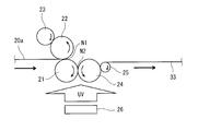
- FIG. 2 is a view showing a method of manufacturing the antiglare film according to the third embodiment.
- an ultraviolet curable resin is used as the curable resin.
- the base film 20 a is unwound from an unillustrated unrolling roll and conveyed in a predetermined direction.
- the downstream end of the base film 20a in the transport direction is inserted into the nip point N1 of the pair of rolls 21 and 22.
- the UV curable resin precursor is attached to the circumferential surface of the roll 22 from the circumferential surface of the roll 23 axially supported adjacent to the roll 22.
- this ultraviolet curable resin precursor is applied to one surface of the base film 20a.
- the layer of the ultraviolet curable resin precursor applied to the base film 20a (hereinafter, referred to as a coat layer) is pressed together with the base film 20a at the nip point of the rolls 21 and 24.
- the roll 24 is a roll-shaped mold (emboss roll) in which fine asperities are formed on the circumferential surface, and transfers the asperity shape to the surface of the coating layer when passing through the nip point N2 of the rolls 21 and 24.
- the coating layer having the uneven shape transferred onto the surface by the roll 24 is cured by the ultraviolet light emitted from the ultraviolet lamp 26 provided below the rolls 21 and 24. Thereby, the antiglare layer 33 is formed.
- the antiglare film 33 manufactured in this manner is released from the roll 24 by the roll 25 axially supported adjacent to the roll 24 and conveyed in a predetermined direction.
- the concavo-convex portion on the surface of the roll 24 is formed by striking blast particles having a predetermined particle diameter by a blast method, and by adjusting the blast particle diameter, the coat layer of the antiglare film 33 is formed. It is possible to adjust the uneven shape to be formed.
- a PET (polyethylene terephthalate) film, a TAC (triacetyl cellulose) film, a COP (cycloolefin polymer) film, an acrylic resin film, and a polycarbonate resin film can be suitably used.
- the step (a) of applying a curable resin precursor to the base film, and a roll having an uneven shape on the surface by striking blast particles Step (b) for producing a cylindrical mold, and (c) for transferring the concavo-convex shape onto the surface of the curable resin precursor applied to the substrate film using this roll-like mold, and transferring the concavo-convex shape Curing the curable resin precursor to form an antiglare layer having a concavo-convex shape on the surface, and (d).
- the average particle diameter of the blast particle used in step (b) can be set suitably, as an example, it can set to the value of the range of 10 micrometers or more and 50 micrometers or less.
- the average particle diameter of the blast particles is more preferably in the range of 20 ⁇ m to 45 ⁇ m, and more preferably in the range of 30 ⁇ m to 40 ⁇ m.
- the mold used in the third embodiment may be other than a roll-shaped mold, and may be, for example, a plate-shaped mold (embossed plate).
- a coat layer (resin layer) is formed on one side of the base film
- the surface of the coat layer is shaped using a mold, and the coat layer is cured to form the antiglare layer 33. It is also good. Further, in the above-described example, the coat layer is cured after shaping of the surface of the coat layer, but shaping and curing of the coat layer may be performed in parallel.
- the material of the mold can be exemplified by metal, plastic and wood.
- a coating may be provided on the surface of the mold in contact with the coating layer in order to improve the durability (abrasion resistance) of the mold.
- the material of the blast particles can be exemplified by metal, silica, alumina and glass.
- the blast particles can, for example, be bombarded on the surface of the mold by gas or liquid pressure.
- an electron beam source such as an electron beam accelerator can be used instead of the ultraviolet lamp 26, and if it is thermosetting, heating such as a heater can be used instead of the ultraviolet lamp 26. Source available.
- the light incident on the antiglare film is the difference in refractive index between the matrix resin in the antiglare layer and the fine particles.
- the antiglare film can be well prevented from being colored by scattering at a wide angle.
- the anti-glare layer of the anti-glare film which concerns on said each embodiment may further have the upper layer arrange
- the thickness of the upper layer can be set as appropriate, but can be set to, for example, a value in the range of 0.5 ⁇ m to 20 ⁇ m.
- the thickness of the upper layer is more preferably in the range of 2.0 ⁇ m to 12 ⁇ m, and more preferably in the range of 3.0 ⁇ m to 8.0 ⁇ m.
- FIG. 3 is a schematic view of the glaring inspection machine 10.
- the glare inspection machine 10 is a device for evaluating the glare of the display 16a in the display device 16 having a film such as an antiglare film mounted on the surface thereof, and comprises a housing 11, an imaging device 12, a holding unit 13, and a frame 14 for imaging device. , A display stand 15, and an image processing unit 17.
- a glaring inspection machine 10 marketed, Komatsu NTC Co., Ltd. product "film glaring inspection machine" is mentioned.
- the housing 11 has a dark room for imaging the display 16 a by the imaging device 12.
- the imaging device 12, the holding unit 13, the imaging device mount 14, the display device mount 15, and the display device 16 to be evaluated are accommodated.
- the imaging device 12 is, for example, an area camera having a lens 18 and an imaging element, and captures an image displayed on the display 16a.
- the imaging device 12 is connected to the image processing device 17, and is held by the holding unit 13 so that the lens 18 and the display 16a face each other. Image data captured by the imaging device 12 is transmitted to the image processing device 17.
- the holding unit 13 extends in the vertical direction, and holds the imaging device 12 while being fixed to the imaging device rack 14 at the lower end.
- the holding unit 13 holds the imaging device 12 such that the relative distance between the display 16 a and the lens 18 can be changed by moving the imaging device 12 relative to the display device 16 in the vertical direction.
- the display device 16 is placed on the upper surface of the display device mount 15 in a state in which the display 16 a on which the film is mounted is opposed to the imaging device 12.
- the display mount frame 15 supports the surface of the display 16a on which the film is mounted so as to face the imaging device 12 and to be horizontal, and moves the display device 16 relative to the imaging device 12 in the vertical direction.
- the image displayed on the display 16a is imaged per unit pixel (for example, one pixel) of the imaging device of the imaging device 12
- the pixel size of the image is adjusted.
- the image processing device 17 performs data processing of image data captured by the imaging device 12. Specifically, the image processing device 17 obtains the standard deviation of the luminance of the display 16 a from the image data captured by the imaging device 12.
- the image processing apparatus 17 includes an input unit to which image data captured by the imaging device 12 is input, an image processing unit that performs image processing on the input image data, and a result processed by the image processing unit.
- An output unit or the like for outputting to a display device or a printing device is provided.
- the focal length of the imaging device 12 may be changed.
- the display 16a having a film mounted on the surface is displayed in advance by uniform light emission in one color (for example, green).
- an adjustment step is performed to adjust the pixel size of the display 16a on which the film to be imaged is mounted per unit pixel of the imaging element of the imaging device 12.
- the adjustment step in the image taken by the imaging device 12 according to the number of effective pixels of the imaging device of the imaging device 12, even if there is no bright line by pixels or bright lines by pixels, it affects the evaluation of glare of the display 16a.
- the relative distance between the imaging device 12 and the film-mounted display 16a is adjusted to such an extent that
- the relative distance between the imaging device 12 and the display device 16 may be set in consideration of the mode of use of the display device 16 (for example, the relative distance between the user's eyes and the surface of the display 16a). desirable.
- the setting step of setting the measurement area for evaluating the glare of the display 16a mounted with the film is performed.
- the measurement area is appropriately set according to, for example, the size of the display 16a.
- an imaging step of imaging the measurement area of the display 16a on which the film is mounted by the imaging device 12 is performed.
- at least one of the exposure time of the imaging device 12 or the luminance of all the pixels of the display 16a is obtained so that image data can be obtained as a grayscale image with 8-bit gradation display and an average luminance of 170 gradations. adjust.
- the image data captured in the imaging step is input to the image processing device 17.
- the image processing device 17 After the imaging step, the image processing device 17 performs an operation step of obtaining a variation in luminance in the measurement area of the display 16a on which the film is mounted, using the image data. In this calculation step, the variation in luminance is quantified as the standard deviation of the luminance distribution.
- the glare of the display 16a on which the film is mounted becomes larger as the variation in luminance of the display 16a on which the film is mounted is larger.
- the glare of the display 16a is smaller as the value of the standard deviation of the luminance distribution is smaller.
- the bright line of the display 16a mounted with the film is adjusted to such an extent that it does not affect the evaluation of the glare of the display 16a. Therefore, the uneven brightness due to the bright line is suppressed and the accurate glare of the display 16a is evaluated. be able to.
- the standard deviation of the luminance distribution of the display 16a having the film mounted on the surface can be determined, and the value of the display 16a can be evaluated by the value.
- Example and Comparative Example The present invention will be described in more detail based on examples given below, but the present invention is not limited by these examples.
- the phase separation structure is a basic structure, and the antiglare layer 3 containing a predetermined component is formed.
- Example 5 is for forming an antiglare layer in which the haze value is increased by beads (silica fine particles).
- Comparative Example 1 is to form an antiglare layer in which the haze value is increased by beads (zirconia fine particles).
- Comparative Examples 2 and 3 form an antiglare layer having a phase separation structure.
- Comparative Examples 4 and 5 form an antiglare layer in which the haze value is increased by beads (acrylic fine particles).
- Comparative Example 6 is to form an antiglare layer in which the haze value is increased by beads (silica fine particles).
- Comparative Examples 7 to 9 form an antiglare layer in which the haze value is increased by high refractive index beads (polystyrene fine particles etc.).
- irregularities are formed on the surface of the transparent resin coated on the substrate film by embossing to form an antiglare layer.
- the refractive index described in description of a following example and a comparative example shows the refractive index after bridge
- Acrylic polymer A having a polymerizable group “Cyclomer P” manufactured by Daicel Ornex Co., Ltd., refractive index 1.51
- Silicone acrylate Daicel Ornex Co., Ltd.
- EB 1360 refractive index 1.52
- Urethane Acrylate "UA-53H” manufactured by Shin-Nakamura Chemical Co., Ltd.
- Photo initiator B "IRGACURE 907" manufactured by BASF Japan Ltd.
- Polyethylene terephthalate (PET) film “Diafoil” manufactured by Mitsubishi Plastics Co., Ltd.
- Cellulose triacetate (TAC) film “Fujitack TG60UL” manufactured by Fuji Film Co., Ltd.
- This solution is cast on a PET film (substrate film 2) using a wire bar (# 20), and then allowed to stand in an oven at 80 ° C. for 1 minute to evaporate the solvent to a thickness of about 9 ⁇ m. A coat layer was formed.
- the coated layer was irradiated with ultraviolet light for about 5 seconds by a high pressure mercury lamp to perform ultraviolet curing treatment of the coated layer. Thereby, the antiglare layer 3 was formed, and the antiglare film of Example 1 was obtained.
- Example 2 15.0 parts by weight of an acrylic polymer A having a polymerizable group, 3 parts by weight of cellulose acetate propionate, 150 parts by weight of a nanosilica-containing acrylic ultraviolet curable compound A, 1 part by weight of silicone acrylate, 1 part by weight of a photoinitiator A
- a solution was prepared by dissolving 1 part by weight of a photoinitiator B in a mixed solvent of 101 parts by weight of methyl ethyl ketone and 24 parts by weight of 1-butanol.
- This solution is cast on a PET film (substrate film 2) using a wire bar (# 20), and then allowed to stand in an oven at 80 ° C. for 1 minute to evaporate the solvent to a thickness of about 9 ⁇ m. A coat layer was formed.
- the coated layer was irradiated with ultraviolet light for about 5 seconds by a high pressure mercury lamp to perform ultraviolet curing treatment of the coated layer. Thereby, the antiglare layer 3 was formed, and the antiglare film of Example 2 was obtained.
- Example 3 12.5 parts by weight of an acrylic polymer A having a polymerizable group, 5.5 parts by weight of a cellulose acetate propionate, 149.2 parts by weight of a nanosilica-containing acrylic UV curable compound A, a fluorine compound having a polymerizable group 0.1 parts by weight of B, 1 part by weight of photoinitiator A and 1 part by weight of photoinitiator B are dissolved in a mixed solvent of 129 parts by weight of methyl ethyl ketone, 24 parts by weight of 1-butanol and 13 parts by weight of 1-methoxy-2-propanol The solution was prepared.
- This solution is cast on a PET film (substrate film 2) using a wire bar (# 16), and then allowed to stand in an oven at 80 ° C. for 1 minute to evaporate the solvent to a thickness of about 7 ⁇ m. A coat layer was formed.
- the coated layer was irradiated with ultraviolet light for about 5 seconds by a high pressure mercury lamp to perform ultraviolet curing treatment of the coated layer. Thereby, the antiglare layer 3 was formed, and the antiglare film of Example 3 was obtained.
- Example 4 50 parts by weight of acrylic polymer A having a polymerizable group, 2.5 parts by weight of cellulose acetate propionate, 79.5 parts by weight of urethane acrylate, 1 part by weight of silicone acrylate, 1 part by weight of photoinitiator A, 1 part by weight of photoinitiator B A part was dissolved in a mixed solvent of 106 parts by weight of methyl ethyl ketone, 28 parts by weight of 1-butanol and 70 parts by weight of cyclohexanone to prepare a solution.
- This solution is cast on a PET film (substrate film 2) using a wire bar (# 12), and then allowed to stand in an oven at 80 ° C. for 1 minute to evaporate the solvent to a thickness of about 5 ⁇ m. A coat layer was formed.
- the coated layer was irradiated with ultraviolet light for about 5 seconds by a high pressure mercury lamp to perform ultraviolet curing treatment of the coated layer. Thereby, the antiglare layer 3 was formed, and the antiglare film of Example 4 was obtained.
- Example 5 A solution was prepared by mixing 25 parts by mass of the acrylic hard coat formulation A, 25 parts by mass of the silica-containing acrylic ultraviolet curable compound, and 50 parts by mass of 1-butanol. This solution is cast on a PET film (substrate film 2) using a wire bar (# 16), and then allowed to stand in an oven at 80 ° C. for 1 minute to evaporate the solvent to a thickness of about 7 ⁇ m. A coat layer was formed. Then, the coating layer was irradiated with ultraviolet light for about 5 seconds using an ultraviolet lamp to perform ultraviolet curing, whereby the antiglare layer 3 was formed, and the antiglare film of Example 5 was obtained.
- Comparative Example 1 50 parts by weight of dipentaerythritol hexaacrylate, 50 parts by weight of pentaerythritol tetraacrylate, 100 parts by weight of a zirconia fine particle dispersion, 2 parts by weight of a photoinitiator A, 1 part by weight of a photoinitiator B, 116 parts by weight of methyl ethyl ketone and 1 A solution was prepared by dissolving in a mixed solvent of 19 parts by weight of butanol and 58 parts by weight of 1-methoxy-2-propanol.
- This solution is cast on a PET film (substrate film 2) using a wire bar (# 14), and then allowed to stand in an oven at 80 ° C. for 1 minute to evaporate the solvent to a thickness of about 6 ⁇ m. A coat layer was formed.
- the coated layer was irradiated with ultraviolet light for about 5 seconds by a high pressure mercury lamp to perform ultraviolet curing treatment of the coated layer. Thereby, an antiglare layer was formed, and an antiglare film of Comparative Example 1 was obtained.
- Comparative Example 2 5.7 parts by weight of an acrylic polymer A having a polymerizable group, 1.2 parts by weight of cellulose acetate propionate, 4 parts by weight of dipentaerythritol hexaacrylate, 2.77 parts by weight of silicone acrylate, 0. A solution was prepared by dissolving 5 parts by weight in a mixed solvent of 25 parts by weight of methyl ethyl ketone and 12.2 parts by weight of 1-butanol.
- This solution is cast on a PET film (substrate film) using a wire bar (# 24), and then allowed to stand in an oven at 80 ° C. for 1 minute to evaporate the solvent and coat about 7 ⁇ m in thickness. A layer was formed.
- the coated layer was irradiated with ultraviolet light for about 5 seconds by a high pressure mercury lamp to perform ultraviolet curing treatment of the coated layer.
- An antiglare layer was thereby formed, and an antiglare film of Comparative Example 2 was obtained.
- Comparative Example 3 4.1 parts by weight of an acrylic polymer A having a polymerizable group, 1.2 parts by weight of cellulose acetate propionate, 4 parts by weight of dipentaerythritol hexaacrylate, 2.77 parts by weight of silicone acrylate, 0. Five parts by weight were dissolved in a mixed solvent of 25 parts by weight of methyl ethyl ketone and 12.2 parts by weight of 1-butanol. This solution is cast on a PET film (substrate film) using a wire bar (# 22), and then allowed to stand in an oven at 100 ° C. for 1 minute to evaporate the solvent and coat it to a thickness of about 6 ⁇ m. A layer was formed.
- the coated layer was irradiated with ultraviolet light for about 5 seconds by a high pressure mercury lamp to perform ultraviolet curing treatment of the coated layer. Thereby, an antiglare layer was formed, and an antiglare film of Comparative Example 3 was obtained.
- Comparative Example 4 63 parts by weight of an acrylic hardcoat formulation A and 37 parts by weight of an acrylic hardcoat formulation B were mixed. This solution is cast on a TAC film (substrate film) using a wire bar (# 10) and then left in an oven at 100 ° C. for 1 minute to evaporate the solvent and coat about 6 ⁇ m in thickness. A layer was formed.
- the coated layer was irradiated with ultraviolet light for about 5 seconds by a high pressure mercury lamp to perform ultraviolet curing treatment of the coated layer.
- An antiglare layer was thereby formed, and an antiglare film of Comparative Example 4 was obtained.
- Comparative Example 5 32 parts by weight of acrylic hard coat formulation A and 68 parts by weight of acrylic hard coat formulation B were mixed. This solution is cast on a TAC film (substrate film) using a wire bar (# 10) and then left in an oven at 100 ° C. for 1 minute to evaporate the solvent and coat about 6 ⁇ m in thickness. A layer was formed.
- the coated layer was irradiated with ultraviolet light for about 5 seconds by a high pressure mercury lamp to perform ultraviolet curing treatment of the coated layer. Thereby, an antiglare layer was formed, and an antiglare film of Comparative Example 5 was obtained.
- Comparative Example 6 As a base film, a 125- ⁇ m-thick transparent polyester film (Tohobo Co., Ltd., Cosmo Shine A4300) was used. Opstar Z7501 (manufactured by JSR Corporation, 50% solid content), which is an organic-inorganic hybrid type ionizing radiation curable resin composition, is used as a transparent resin, and OK-500 (Degusa Co., Ltd.), which is translucent silica particles, is used for this. And 8.5 parts by weight of an average particle system of 3.0 ⁇ m and a refractive index of 1.46) with respect to 200 parts by weight of the transparent resin.
- Opstar Z7501 manufactured by JSR Corporation, 50% solid content
- OK-500 Degusa Co., Ltd.
- Irgacure 651 manufactured by BASF Corp.
- butyl acetate butyl acetate
- Comparative Example 7 As a base film, triacetyl cellulose (Fuji Film Co., Ltd. product, 80 micrometers in thickness) was prepared. As a transparent resin, pentaerythritol triacrylate (PETA; manufactured by Daicel Ornex Co., Ltd., refractive index 1.51) is used, and as the light transmitting particles, styrene-acrylic copolymer particles (refractive index 1.51, average particle size) are used. 10.0 parts by weight and 16.5 parts by weight of polystyrene particles (refractive index 1.60, average particle size 3.5 ⁇ m) with respect to 100 parts by weight of the transparent resin were respectively contained. .
- PETA pentaerythritol triacrylate
- styrene-acrylic copolymer particles reffractive index 1.51, average particle size
- a resin composition obtained by blending 190 parts by weight of a mixed solvent (weight ratio 7: 3) of toluene (boiling point 110 ° C.) and cyclohexanone (boiling point 156 ° C.) as a solvent with 100 parts by weight of a transparent resin was applied to a substrate film, dried at 85 ° C. at a flow rate of 1 m / s, and dried for 1 minute.
- Comparative Example 8 As a base film, triacetyl cellulose (Fuji Film Co., Ltd. product, 80 micrometers in thickness) was prepared.
- PETA pentaerythri
- the resultant was applied to a substrate film, dried air was passed at 70.degree. C. at a flow rate of 0.2 m / s, and dried for 1 minute.
- the transparent resin was cured by irradiation with ultraviolet light (200 mJ / cm 2 in a nitrogen atmosphere) to form an antiglare layer, whereby an antiglare film of Comparative Example 8 was obtained.
- the coating thickness was 3.5 ⁇ m.
- Comparative Example 9 As a base film, triacetyl cellulose (Fuji Film Co., Ltd. product, 80 micrometers in thickness) was prepared. As a transparent resin, pentaerythritol triacrylate (PE-3A; manufactured by Kyoeisha Chemical Co., Ltd., refractive index: 1.53) is used, and as light transmitting particles, silica particles (SS50F; manufactured by Tosoh Silica Industry Co., Ltd.) 26 parts by weight and 6.6 parts by weight of a refractive index of 1.47 and an average particle size of 1.1 ⁇ m and polystyrene particles (refractive index 1.59 and an average particle size of 3.5 ⁇ m) with respect to 100 parts by weight of the transparent resin Part was included.
- PE-3A pentaerythritol triacrylate
- SS50F silica particles
- SS50F manufactured by Tosoh Silica Industry Co., Ltd.
- a resin composition obtained by compounding 5.3 parts by weight of Irgacure 184 (manufactured by BASF Corp.) as a photopolymerization initiator and 138 parts by weight of toluene (boiling point 110 ° C.) as a solvent is coated on a base film Then, dry air of 90.degree. C. was circulated at a flow rate of 0.2 m / s and dried for 1 minute.
- the transparent resin was cured by irradiation with ultraviolet light (200 mJ / cm 2 in a nitrogen atmosphere) to form an antiglare layer, whereby an antiglare film of Comparative Example 9 was obtained.
- the coating thickness was 5 ⁇ m.
- Comparative Examples 10 and 11 The antiglare films of Comparative Examples 10 and 11 were prepared by forming a coating layer made of an ultraviolet curable resin on the surface of which unevenness was transferred using a mold, as shown in FIG. .
- Example 5 and Comparative Examples 2 to 5 as shown in FIG. 3, the base film 20a unwound and conveyed from the unrolling roll is inserted into the nip point of the pair of rolls 21 and 22.
- the UV curable resin precursor was adhered to the circumferential surface of the roll 22 from the circumferential surface of the roll 23 axially supported adjacent to the roll 22, and this UV curable resin precursor was applied to the upper surface of the base film 20a.
- the applied UV curable resin precursor was pressed together with the base film 20a at the nip point N1 of the rolls (roll-like molds) 21 and 24. Thereby, when the applied ultraviolet curing resin precursor passes through the nip point N1 of the rolls 21 and 24 together with the base film 20a, the uneven shape is transferred to the surface of the ultraviolet curing resin precursor.
- the UV curable resin precursor to which the concavo-convex shape was transferred by the roll 24 was cured by UV light emitted from a UV lamp provided below the rolls 21 and 24 to form a coated layer (antiglare layer).
- the antiglare film thus obtained was released from the roll 24 by the roll 25 axially supported adjacent to the roll 24 and conveyed in a predetermined direction.
- a TAC (triacetyl cellulose) film was used as a base film.
- the value of blast particle diameter is changed in the range of 30 ⁇ m to 40 ⁇ m to manufacture a roll-shaped mold.
- Two types of films (Comparative Examples 10 and 11) having different haze (Hz) values were produced by the above production method.
- the adhesive layer was omitted in the measurement of the haze, the total light transmittance, the transmitted image definition, and the 60 degree gloss.
- At least one of the exposure time of the imaging device 12 or the luminance of all the pixels of the display 16a is selected so that image data can be obtained as a grayscale image with an 8-bit gradation display and an average luminance of 170 gradations. It was adjusted.
- the measurement results are shown in Tables 1 and 2.
- the transmission image definition of the optical comb width 0.5 mm is set to a value in the range of 3% to 40%, and the antiglare layer 3
- the haze value of is set in the range of 55.5% to 93.0%.
- the glare value (glare s) of the display 16a is suppressed to a value in the range of 4.2 or more and 6.0 or less. That is, it was found that in the antiglare films 1 of Examples 1 to 5, good antiglare properties were obtained while suppressing the glare value of the display.
- phase separation occurs between the acrylic copolymer A and the cellulose acetate propionate, and at the same time, the nanosilica-containing acrylic ultraviolet curable compound A or urethane acrylate It is considered that the phase separation structure is emphasized, and the surface of the antiglare layer 3 can be formed into a structure having a very sharp or high / low difference.
- the aggregation of the silica particles is vigorously generated by adding a large amount of butanol which is a solvent having a low affinity to the silica particles in the silica-containing acrylic ultraviolet curable compound.
- the surface of the antiglare layer 3 could be formed into a structure having a very sharp or a difference in height. That is, it is considered that the concavo-convex structure formed on the surface of the antiglare layer 3 is emphasized to such an extent that it can not occur in a solvent having high affinity, because the silica particles generate repulsive interaction with butanol.
- the optical performance could be adjusted to the range shown in Table 1 by making the acrylic ultraviolet curing resin and the acrylic hard coat formulation A coexist.
- Comparative Examples 1 to 6 and 11 have relatively high transmission image definition and 60 degree gloss values, respectively, as compared to Examples 1 to 5.
- Comparative Examples 7 to 9 have relatively low values of transmitted image definition but relatively high values of 60 degree gloss
- Comparative Example 10 has relatively low values of 60 degree gloss but the transmission image definition The value is relatively high.
- Comparative Examples 1 to 11 have lower antiglare properties as compared to Examples 1 to 5 because the balance of the transmitted image definition and the 60 degree gloss is not superior to that of Examples 1 to 5. Conceivable.
- the beads zirconia fine particles
- the refractive index difference between the beads contained in the antiglare layer and the matrix resin is 0.2.
- Table 2 in the antiglare film of Comparative Example 1, although the glare value of the display is suppressed to some extent, the values of transmission image definition and 60 degree gloss are high and the antiglare property is not excellent. I understand.
- the antiglare films of Comparative Examples 2 and 3 have the antiglare layer formed by the phase separation structure, but as in Examples 1 to 4, since the phase separation structure of the antiglare layer is not emphasized, Examples It was found that the antiglare property was not excellent as compared with 1-4.
- Comparative Examples 4 to 6 it is difficult to increase the haze value compared to Examples 1 to 5 because the difference in refractive index between the beads contained in the antiglare layer and the matrix resin is small, and while suppressing the glare value of the display It turned out that it is difficult to obtain good antiglare properties.
- the haze value of the antiglare layer is increased to some extent by adjusting the internal haze value of the antiglare layer with high refractive index beads (polystyrene fine particles etc.) as in Examples 1 to 5. It turned out that it is difficult to obtain good antiglare properties while suppressing the glare value of the display.
- Comparative Examples 10 and 11 have the antiglare layer in which unevenness is formed by embossing on the surface, but as in Examples 1 to 5, good antiglare properties can be achieved while suppressing the glare value of the display. It turned out to be difficult to obtain.
- the glare value of the display 16a is set to a value in the range of 0 or more and less than 4.2 according to the tendency of the characteristics shown in the examples 1 to 5 and another study conducted by the present inventors.
- the transmission image definition of the optical comb width 0.5 mm of the film 1 is set to a value in the range of 0% or more and less than 8.4% and 55% or more and 60% or less, and the haze value of the antiglare layer 3 is Even when the value is set in the range of 50% to less than 55.5, and more than 93.0 and 99.0% or less, it is considered that the same effect as in the examples 1 to 5 is exerted.
Landscapes
- Chemical & Material Sciences (AREA)
- Physics & Mathematics (AREA)
- Organic Chemistry (AREA)
- Engineering & Computer Science (AREA)
- General Physics & Mathematics (AREA)
- Health & Medical Sciences (AREA)
- Chemical Kinetics & Catalysis (AREA)
- Medicinal Chemistry (AREA)
- Polymers & Plastics (AREA)
- Optics & Photonics (AREA)
- Materials Engineering (AREA)
- Wood Science & Technology (AREA)
- Life Sciences & Earth Sciences (AREA)
- Theoretical Computer Science (AREA)
- Manufacturing & Machinery (AREA)
- Dispersion Chemistry (AREA)
- Toxicology (AREA)
- Inorganic Chemistry (AREA)
- General Chemical & Material Sciences (AREA)
- Optical Elements Other Than Lenses (AREA)
- Laminated Bodies (AREA)
- Electroluminescent Light Sources (AREA)
- Devices For Indicating Variable Information By Combining Individual Elements (AREA)
- Coating Of Shaped Articles Made Of Macromolecular Substances (AREA)
- Treatments Of Macromolecular Shaped Articles (AREA)
Abstract
Description
図1は、第1実施形態に係る防眩フィルム1の構成を示す断面図である。防眩フィルム1は、表示装置16(図3参照)のディスプレイ16aの表面に装着される。防眩フィルム1は、基材フィルム2、防眩層3、及び粘着層4を備える。
第1実施形態の防眩層3は、複数の樹脂成分の相分離構造を有する。防眩層3は、一例として、複数の樹脂成分の相分離構造により、複数の長細状(紐状又は線状)凸部が表面に形成されている。長細状凸部は分岐しており、密な状態で共連続相構造を形成している。
防眩層3が含む複数の樹脂成分は、相分離可能なものであればよいが、長細状凸部が形成され且つ高い耐擦傷性を有する防眩層3を得る観点から、ポリマー及び硬化性樹脂を含むことが好ましい。
調製工程では、溶媒と、防眩層3を構成するための樹脂組成物と、所定の微粒子を含む溶液を調製する。溶媒は、前述した防眩層3に含まれるポリマー及び硬化性樹脂前駆体の種類及び溶解性に応じて選択できる。溶媒は、少なくとも固形分(複数種類のポリマー及び硬化性樹脂前駆体、反応開始剤、その他添加剤)を均一に溶解できるものであればよい。
形成工程では、調製工程で調製した溶液を、支持体(ここでは一例として基材フィルム2)の表面に流延又は塗布する。溶液の流延方法又は塗布方法としては、慣用の方法、例えば、スプレー、スピナー、ロールコーター、エアナイフコーター、ブレードコーター、ロッドコーター、リバースコーター、バーコーター、コンマコーター、ディップ、ディップ・スクイズコーター、ダイコーター、グラビアコーター、マイクログラビアコーター、シルクスクリーンコーター等を例示できる。
硬化工程では、溶液中の硬化性樹脂前駆体を硬化させることで、形成工程で形成された相分離構造を固定化し、防眩層3を形成する。硬化性樹脂前駆体の硬化は、硬化性樹脂前駆体の種類に応じて、加熱又は活性エネルギー線の照射、或いはこれらの方法の組み合わせにより行う。照射する活性エネルギー線は、光硬化成分等の種類に応じて選択する。
第2実施形態に係る防眩フィルムの防眩層は、マトリクス樹脂と、マトリクス樹脂中に分散された複数の微粒子を含む。微粒子は、真球状に形成されているが、これに限定されず、実質的な球状や楕円体状に形成されていてもよい。また微粒子は、中実に形成されているが、中空に形成されていてもよい。微粒子が中空に形成されている場合、微粒子の中空部には、空気或いはその他の気体が充填されていてもよい。防眩層には、各微粒子が一次粒子として分散していてもよいし、複数の微粒子が凝集して形成された複数の二次粒子が分散していてもよい。
調製工程では、溶媒と、防眩層を構成するための樹脂組成物と、微粒子とを含む溶液を調製する。溶媒としては、アルコール類(イソプロピルアルコール、メタノール、エタノール等)、ケトン類(メチルエチルケトン(MEK)、メチルイソブチルケトン(MIBK)、シクロヘキサノン等)、エステル類(酢酸メチル、酢酸エチル、酢酸ブチル等)、ハロゲン化炭化水素、芳香族炭化水素(トルエン、キシレン等)の少なくともいずれかを例示できる。溶液には、更に公知のレベリング剤を添加してもよい。例えば、フッ素系やシリコーン系のレベリング剤を用いることにより、防眩層に良好な耐擦傷性を付与できる。
塗布工程では、調製工程で調製した溶液を、第1実施形態と同様の方法により、支持体(ここでは一例として基材フィルム2)の表面に流延又は塗布する。支持体の表面に流延又は塗布した溶液から、溶媒を乾燥により蒸発させて除去する。
第3実施形態に係る防眩フィルムの防眩層33は、基材フィルム側とは反対側の表面に凹凸形状が賦形された構造を有する。防眩層33は、樹脂層で構成されている。この樹脂層は、一例として、第2実施形態のマトリクス樹脂と同様の材質により構成されている。
図3は、ギラツキ検査機10の概略図である。ギラツキ検査機10は、表面に防眩フィルム等のフィルムを装着した表示装置16におけるディスプレイ16aのギラツキを評価する装置であって、筐体11、撮像装置12、保持部13、撮像装置用架台14、表示装置用架台15、及び画像処理装置17を備える。市販されているギラツキ検査機10としては、コマツNTC(株)製「フィルムギラツキ検査機」が挙げられる。
次に、ギラツキ検査機10を用いたディスプレイ16aのギラツキ評価方法について説明する。このギラツキ評価方法では、評価の便宜上、表面にフィルムを装着したディスプレイ16aを予め一色(一例として緑色)に均一発光させて表示させる。
以下に、実施例に基づいて本発明をより詳細に説明するが、本発明はこれらの実施例によって限定されるものではない。
実施例及び比較例で用いる各原料には、次のものを用いた。
重合性基を有するアクリル系重合体A:ダイセル・オルネクス(株)製「サイクロマーP」、屈折率1.51
セルロースアセテートプロピオネート:イーストマン社製「CAP-482-20」、アセチル化度=2.5%、プロピオニル度=46%、ポリスチレン換算の数平均分子量75000、屈折率1.49
シリコーンアクリレート:ダイセル・オルネクス(株)製「EB1360」、屈折率1.52
ウレタンアクリレート:新中村化学工業(株)製「UA-53H」
ジペンタエリスリトールヘキサアクリレート:ダイセル・オルネクス(株)製「DPHA」、屈折率1.52
ペンタエリスリトールテトラアクリレート:ダイセル・オルネクス(株)製「PETRA」、屈折率1.52
ナノシリカ含有アクリル系紫外線硬化性化合物A:モメンティブ・パフォーマンス・マテリアルズ・ジャパン(合同会社)製「UVHC-7800」
シリカ(屈折率1.46)含有アクリル系紫外線硬化性化合物:アイカ工業(株)製「Z-753-11R」、屈折率1.52
アクリル系ハードコート配合物A:日本化工塗料(株)製「FA-3155クリア」、アクリル微粒子(屈折率1.50)とマトリクス樹脂(屈折率1.46)を含有する
アクリル系ハードコート配合物B:日本化工塗料(株)製「FA-3155M」、屈折率1.46
重合性基を有するフッ素系化合物A:信越化学工業(株)製「KY-1203」
重合性基を有するフッ素系化合物B:(株)ネオス製「フタージェント602A」
ジルコニア微粒子(屈折率約20分散液:東洋インキ(株)製「リオデュラスTYZ」
光開始剤A:BASFジャパン(株)製「イルガキュア184」
光開始剤B:BASFジャパン(株)製「イルガキュア907」
ポリエチレンテレフタレート(PET)フィルム:三菱樹脂(株)製「ダイアホイル」
セルローストリアセテート(TAC)フィルム:富士フイルム(株)製「フジタックTG60UL」
重合性基を有するアクリル系重合体A15.0重量部、セルロースアセテートプロピオネート3重量部、ナノシリカ含有アクリル系紫外線硬化性化合物Aの150重量部、シリコーンアクリレート1重量部、光開始剤A1重量部、光開始剤B1重量部を、メチルエチルケトン101重量部と1-ブタノール24重量部との混合溶媒に溶解し、溶液を調製した。
重合性基を有するアクリル系重合体A12.5重量部、セルロースアセテートプロピオネート5.5重量部、ナノシリカ含有アクリル系紫外線硬化性化合物Aの149.2重量部、重合性基を有するフッ素系化合物B0.1重量部、光開始剤A1重量部、光開始剤B1重量部を、メチルエチルケトン129重量部と1-ブタノール24重量部と1-メトキシ-2-プロパノール13重量部との混合溶媒に溶解し、溶液を調製した。
重合性基を有するアクリル系重合体A50重量部、セルロースアセテートプロピオネート2.5重量部、ウレタンアクリレート79.5重量部、シリコーンアクリレート1重量部、光開始剤A1重量部、光開始剤B1重量部を、メチルエチルケトン106重量部と1-ブタノール28重量部とシクロヘキサノン70重量部との混合溶媒に溶解し、溶液を調製した。
アクリル系ハードコート配合物A25質量部とシリカ含有アクリル系紫外線硬化性化合物25質量部と1-ブタノール50質量部とを混合した溶液を調製した。この溶液を、ワイヤーバー(#16)を用いて、PETフィルム(基材フィルム2)上に流延した後、80℃のオーブン内で1分間放置し、溶媒を蒸発させて厚さ約7μmのコート層を形成した。そして、紫外線ランプにより紫外線をコート層に約5秒間照射して紫外線硬化処理し、これにより防眩層3を形成し、実施例5の防眩フィルムを得た。
ジペンタエリスリトールヘキサアクリレート50重量部、ペンタエリスリトールテトラアクリレート50重量部、ジルコニア微粒子分散液100重量部、光開始剤Aの2重量部、光開始剤Bの1重量部を、メチルエチルケトン116重量部と1-ブタノール19重量部と1-メトキシ-2-プロパノール58重量部との混合溶媒に溶解し、溶液を調製した。
重合性基を有するアクリル系重合体A5.7重量部、セルロースアセテートプロピオネート1.2重量部、ジペンタエリスリトールヘキサアクリレート4重量部、シリコーンアクリレート2.77重量部、光開始剤Aの0.5重量部を、メチルエチルケトン25重量部と1-ブタノール12.2重量部との混合溶媒に溶解し、溶液を調製した。
重合性基を有するアクリル系重合体A4.1重量部、セルロースアセテートプロピオネート1.2重量部、ジペンタエリスリトールヘキサアクリレート4重量部、シリコーンアクリレート2.77重量部、光開始剤Aの0.5重量部を、メチルエチルケトン25重量部と1-ブタノール12.2重量部との混合溶媒に溶解した。この溶液を、ワイヤーバー(#22)を用いて、PETフィルム(基材フィルム)上に流延した後、100℃のオーブン内で1分間放置し、溶媒を蒸発させて厚さ約6μmのコート層を形成した。
アクリル系ハードコート配合物A63重量部と、アクリル系ハードコート配合物B37重量部とを混合した。この溶液を、ワイヤーバー(#10)を用いて、TACフィルム(基材フィルム)上に流延した後、100℃のオーブン内で1分間放置し、溶媒を蒸発させて厚さ約6μmのコート層を形成した。
アクリル系ハードコート配合物A32重量部と、アクリル系ハードコート配合物B68重量部とを混合した。この溶液を、ワイヤーバー(#10)を用いて、TACフィルム(基材フィルム)上に流延した後、100℃のオーブン内で1分間放置し、溶媒を蒸発させて厚さ約6μmのコート層を形成した。
基材フィルムとして、厚み125μmの透明ポリエステルフィルム(東洋紡(株)製、コスモシャインA4300)を用いた。透明樹脂として有機無機ハイブリッドタイプの電離放射線硬化型樹脂組成物であるオプスターZ7501(JSR(株)製,固形分50%)を用い、これに透光性シリカ粒子であるOK-500(デグサ社製,平均粒子系3.0μm,屈折率1.46)を、透明樹脂200重量部に対して8.5部含有させた。これに光重合開始剤としてイルガキュア651(BASF社製)を1重量部、溶剤として酢酸ブチル(沸点100℃)を200重量部配合して得られた樹脂組成物を、基材フィルムに塗工し、1m/sの流速で85℃の乾燥空気を流通させ、1分間乾燥させた。
基材フィルムとして、トリアセチルセルロース(富士フィルム(株)製、厚さ80μm)を用意した。透明樹脂としてペンタエリスリトールトリアクリレート(PETA;ダイセル・オルネクス(株)製,屈折率1.51)を用い、これに透光性粒子として、スチレン-アクリル共重合粒子(屈折率1.51、平均粒径9.0μm)、及びポリスチレン粒子(屈折率1.60、平均粒径3.5μm)を、それぞれ透明樹脂100重量部に対して、10.0重量部、及び16.5重量部含有させた。これに溶剤としてトルエン(沸点110℃)とシクロヘキサノン(沸点156℃)の混合溶剤(重量比7:3)を、透明樹脂100重量部に対して、190重量部配合して得られた樹脂組成物を、基材フィルムに塗工し、1m/sの流速で85℃の乾燥空気を流通させ、1分間乾燥させた。
基材フィルムとして、トリアセチルセルロース(富士フィルム(株)製、厚さ80μm)を用意した。透明樹脂としてペンタエリスリトールトリアクリレート(PETA;ダイセル・オルネクス(株)製)、ジペンタエリスリトールヘキサアクリレート(DPHA;ダイセル・オルネクス(株)製)、及びポリメタクリル酸メチル(BR85;三菱レーヨン(株)製)の混合物(重量比;PETA/DPHA/PMMA=86/5/9)を用い(屈折率1.51)、これに透光性粒子として、ポリスチレン粒子(屈折率1.60、平均粒径3.5μm)及びスチレン-アクリル共重合粒子(屈折率1.56、平均粒径3.5μm)を、透明樹脂100重量部に対して、各々18.5及び3.5重量部含有させた。これに溶剤としてトルエン(沸点110℃)とシクロヘキサノン(沸点156℃)の混合溶剤(重量比7:3)を、透明樹脂100重量部に対して、190重量部配合して得られた樹脂組成物を、基材フィルムに塗工し、0.2m/sの流速で70℃の乾燥空気を流通させ、1分間乾燥させた。
基材フィルムとして、トリアセチルセルロース(富士フィルム(株)製、厚さ80μm)を用意した。透明樹脂としてペンタエリスリトールトリアクリレート(PE-3A;共栄社化学(株)製,屈折率1.53)を用い、これに透光性粒子として、シリカ粒子(SS50F;東ソー・シリカ工業(株)製,屈折率1.47、平均粒径1.1μm)及びポリスチレン粒子(屈折率1.59、平均粒径3.5μm)を、透明樹脂100重量部に対して、各々26重量部及び6.6重量部含有させた。これに光重合開始剤としてイルガキュア184(BASF社製)を5.3重量部及び溶剤としてトルエン(沸点110℃)を138重量部配合して得られた樹脂組成物を、基材フィルムに塗工し、0.2m/sの流速で90℃の乾燥空気を流通させ、1分間乾燥させた。
比較例10,11の防眩フィルムは、図3に示したように、基材フィルム上に、金型を用いて表面に凹凸が転写された紫外線硬化樹脂からなるコート層を形成して作製した。
ヘイズメーター(日本電色(株)製、NDH-5000W)を用いて、JIS K7136に準拠して測定した。ヘイズは、防眩層の凹凸構造を有する表面が受光器側となるように配置して測定した。
写像測定器(スガ試験機(株)製、ICM-1T)を用いて、JIS K7105に準拠し、防眩フィルムの製膜方向と光学櫛の櫛歯の方向とが平行になるように防眩フィルムを設置して測定した。光学櫛幅は、0.5mmとした。
グロスメーター((株)掘場製作所製、IG-320)を用いて、JlS K7105に準拠し、角度60°で測定した。
表示装置16としてスマートフォン(三星電子(株)製「Galaxy S4」)を用い、そのディスプレイ16aの表面に、各サンプルの防眩フィルムを粘着層(光学糊)により貼り付けた。コマツNTC(株)製フィルムギラツキ検査機10を用い、各サンプルの防眩フィルムを介して、ディスプレイ16aの輝度分布の標準偏差(ギラツキσ:ギラツキ値)を測定した。この測定に際しては、8ビット階調表示で且つ平均輝度が170階調のグレースケール画像として画像データが得られるように、撮像装置12の露光時間又はディスプレイ16aの全画素の輝度の少なくともいずれかを調整した。
各測定結果を表1及び2に示す。

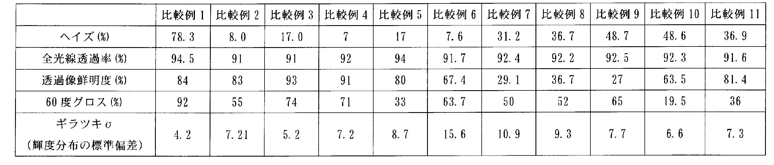
3 防眩層
16a ディスプレイ
Claims (5)
- ヘイズ値が50%以上99%以下の範囲の値である防眩層を備え、
ディスプレイの表面に装着した状態における前記ディスプレイの輝度分布の標準偏差が0以上6以下の範囲の値であり、且つ、光学櫛幅0.5mmの透過像鮮明度が0%以上60%以下の範囲の値である、防眩フィルム。 - 前記防眩層は、複数の樹脂成分を含み、前記複数の樹脂成分の相分離により形成された共連続相構造を有する、請求項1に記載の防眩フィルム。
- 前記防眩層は、アクリル共重合体と、セルロースアセテートプロピオネートと、ナノシリカ含有アクリル系紫外線硬化性化合物及びウレタンアクリレートの少なくとも一方と、を含む、請求項2に記載の防眩フィルム。
- 前記防眩層は、マトリクス樹脂と、マトリクス樹脂中に分散された複数の微粒子を含み、
前記微粒子と前記マトリクス樹脂との屈折率差が、0以上0.07以下の範囲の値である、請求項1に記載の防眩フィルム。 - 前記防眩層の前記マトリクス樹脂の重量G1と、前記防眩層に含まれる前記複数の微粒子の総重量G2との比G2/G1が、0.07以上0.20以下の範囲の値である、請求項4に記載の防眩フィルム。
Priority Applications (6)
| Application Number | Priority Date | Filing Date | Title |
|---|---|---|---|
| US16/610,699 US12534626B2 (en) | 2017-08-04 | 2018-06-25 | Antiglare film |
| KR1020197037551A KR102282272B1 (ko) | 2017-08-04 | 2018-06-25 | 방현 필름 |
| CN202111330165.1A CN114167530B (zh) | 2017-08-04 | 2018-06-25 | 防眩膜 |
| JP2019533964A JP6745410B2 (ja) | 2017-08-04 | 2018-06-25 | 防眩フィルム |
| CN201880037117.3A CN110709734B (zh) | 2017-08-04 | 2018-06-25 | 防眩膜 |
| US17/575,861 US12037513B2 (en) | 2017-08-04 | 2022-01-14 | Antiglare film |
Applications Claiming Priority (2)
| Application Number | Priority Date | Filing Date | Title |
|---|---|---|---|
| JP2017151496 | 2017-08-04 | ||
| JP2017-151496 | 2017-08-04 |
Related Child Applications (2)
| Application Number | Title | Priority Date | Filing Date |
|---|---|---|---|
| US16/610,699 A-371-Of-International US12534626B2 (en) | 2017-08-04 | 2018-06-25 | Antiglare film |
| US17/575,861 Division US12037513B2 (en) | 2017-08-04 | 2022-01-14 | Antiglare film |
Publications (1)
| Publication Number | Publication Date |
|---|---|
| WO2019026468A1 true WO2019026468A1 (ja) | 2019-02-07 |
Family
ID=65233722
Family Applications (1)
| Application Number | Title | Priority Date | Filing Date |
|---|---|---|---|
| PCT/JP2018/023940 Ceased WO2019026468A1 (ja) | 2017-08-04 | 2018-06-25 | 防眩フィルム |
Country Status (5)
| Country | Link |
|---|---|
| US (2) | US12534626B2 (ja) |
| JP (6) | JP6745410B2 (ja) |
| KR (1) | KR102282272B1 (ja) |
| CN (2) | CN110709734B (ja) |
| WO (1) | WO2019026468A1 (ja) |
Cited By (4)
| Publication number | Priority date | Publication date | Assignee | Title |
|---|---|---|---|---|
| WO2023074779A1 (ja) * | 2021-10-28 | 2023-05-04 | 大日本印刷株式会社 | 防眩フィルム、並びに、それを用いた偏光板、表面板、画像表示パネル及び画像表示装置 |
| WO2023074774A1 (ja) * | 2021-10-28 | 2023-05-04 | 大日本印刷株式会社 | 防眩フィルム、並びに、それを用いた偏光板、表面板、画像表示パネル及び画像表示装置 |
| WO2023163150A1 (ja) * | 2022-02-28 | 2023-08-31 | 日東電工株式会社 | Oled表示装置用光学積層体 |
| JP7557601B1 (ja) | 2023-11-14 | 2024-09-27 | 株式会社ダイセル | 防眩フィルム |
Families Citing this family (6)
| Publication number | Priority date | Publication date | Assignee | Title |
|---|---|---|---|---|
| US9110230B2 (en) | 2013-05-07 | 2015-08-18 | Corning Incorporated | Scratch-resistant articles with retained optical properties |
| WO2019026466A1 (ja) * | 2017-08-04 | 2019-02-07 | 株式会社ダイセル | 防眩フィルム |
| KR102417944B1 (ko) | 2017-08-04 | 2022-07-06 | 주식회사 다이셀 | 방현 필름 |
| TWI821234B (zh) | 2018-01-09 | 2023-11-11 | 美商康寧公司 | 具光改變特徵之塗覆製品及用於製造彼等之方法 |
| US12147009B2 (en) | 2020-07-09 | 2024-11-19 | Corning Incorporated | Textured region to reduce specular reflectance including a low refractive index substrate with higher elevated surfaces and lower elevated surfaces and a high refractive index material disposed on the lower elevated surfaces |
| US11978686B2 (en) * | 2022-07-06 | 2024-05-07 | Wuhan Choice Technology Co, Ltd. | Chip protective film and method for manufacturing same, and chip |
Citations (3)
| Publication number | Priority date | Publication date | Assignee | Title |
|---|---|---|---|---|
| JP2003156606A (ja) * | 2001-09-10 | 2003-05-30 | Nitto Denko Corp | 光拡散性シート、光学素子および画像表示装置 |
| WO2007111026A1 (ja) * | 2006-03-29 | 2007-10-04 | Tomoegawa Co., Ltd. | 光学フィルム |
| JP2009180886A (ja) * | 2008-01-30 | 2009-08-13 | Nippon Shokubai Co Ltd | 防眩性積層体 |
Family Cites Families (49)
| Publication number | Priority date | Publication date | Assignee | Title |
|---|---|---|---|---|
| JPS559505A (en) | 1978-07-05 | 1980-01-23 | Ricoh Co Ltd | Transfer and separating device of electrophotographic copier |
| WO1995031737A1 (en) | 1994-05-18 | 1995-11-23 | Dai Nippon Printing Co., Ltd. | Glare-proof film |
| JP4215288B2 (ja) * | 1996-10-31 | 2009-01-28 | 共同印刷株式会社 | 高ヘイズコーティングおよびその形成方法 |
| JP3559505B2 (ja) | 2000-07-24 | 2004-09-02 | ダイセル化学工業株式会社 | 透過型光散乱シート |
| JP3825782B2 (ja) | 2003-01-16 | 2006-09-27 | 住友化学株式会社 | 防眩フィルム及びその製造方法、並びにそれを備えた表示装置 |
| JP2006113561A (ja) | 2004-09-16 | 2006-04-27 | Fuji Photo Film Co Ltd | 光散乱性フィルムの製造方法、該光散乱性フィルムを用いた偏光板、該偏光板を用いた液晶表示装置 |
| JP4709520B2 (ja) | 2004-10-04 | 2011-06-22 | ダイセル化学工業株式会社 | 防眩性フィルム |
| JP4746863B2 (ja) * | 2004-11-11 | 2011-08-10 | リンテック株式会社 | 防眩性ハードコート層形成用材料及び防眩性ハードコートフィルム |
| JP2007045142A (ja) * | 2005-02-22 | 2007-02-22 | Fujifilm Corp | 防眩性フィルム、反射防止フィルム、その製造方法、該フィルムを用いた偏光板および該偏光板を用いた液晶表示装置 |
| JP5340592B2 (ja) | 2005-03-30 | 2013-11-13 | 大日本印刷株式会社 | 防眩性光学積層体 |
| KR100959049B1 (ko) * | 2005-06-28 | 2010-05-20 | 닛토덴코 가부시키가이샤 | 방현성 하드 코트 필름 |
| JP2007108724A (ja) * | 2005-09-16 | 2007-04-26 | Fujifilm Corp | 防眩性反射防止フィルム、これを用いた偏光板および液晶表示装置 |
| JP5015462B2 (ja) * | 2006-01-11 | 2012-08-29 | 株式会社ダイセル | 防眩性フィルム及びその製造方法 |
| KR20090008234A (ko) * | 2006-03-16 | 2009-01-21 | 다이셀 가가꾸 고교 가부시끼가이샤 | 방현성 필름 |
| US8163372B2 (en) | 2006-08-14 | 2012-04-24 | Dai Nippon Printing Co., Ltd. | Anti-dazzling optical laminate |
| JP2008145781A (ja) | 2006-12-11 | 2008-06-26 | Admatechs Co Ltd | アンチグレアフィルム及びその製造方法 |
| JP4958609B2 (ja) * | 2007-04-06 | 2012-06-20 | リンテック株式会社 | 防眩性ハードコートフィルム及びその製造方法 |
| JP5098834B2 (ja) | 2007-06-12 | 2012-12-12 | 東レ株式会社 | 白色反射フィルム |
| TWI607231B (zh) | 2007-07-04 | 2017-12-01 | 琳得科股份有限公司 | 硬被覆膜 |
| JP2009036818A (ja) * | 2007-07-31 | 2009-02-19 | Konica Minolta Opto Inc | 防眩性フィルム、防眩性反射防止フィルム、偏光板および画像表示装置 |
| JP2009048092A (ja) | 2007-08-22 | 2009-03-05 | Tomoegawa Paper Co Ltd | 光学積層体 |
| JP5109585B2 (ja) | 2007-10-30 | 2012-12-26 | 住友化学株式会社 | 光拡散性シート |
| JP2009175041A (ja) | 2008-01-25 | 2009-08-06 | Asahi Kasei Corp | 表示画像のギラツキ評価方法 |
| JP2009244465A (ja) | 2008-03-31 | 2009-10-22 | Nitto Denko Corp | 防眩性ハードコートフィルム、それを用いた液晶パネルおよび液晶表示装置 |
| TWI394985B (zh) * | 2008-05-07 | 2013-05-01 | Ind Tech Res Inst | 抗眩膜及其製造方法 |
| JP5463279B2 (ja) | 2010-12-21 | 2014-04-09 | チェイル インダストリーズ インコーポレイテッド | 防眩フィルム |
| JP6164335B2 (ja) | 2011-03-18 | 2017-07-19 | 株式会社リコー | 画像形成データ生成装置、画像形成データ生成システム、画像形成データ生成方法、画像形成データ生成プログラム |
| JP5653378B2 (ja) | 2011-09-27 | 2015-01-14 | 日本製紙株式会社 | 防眩ハードコートフィルム |
| JP5961049B2 (ja) | 2012-06-26 | 2016-08-02 | 株式会社ダイセル | 光学フィルム及びその製造方法 |
| CN103629594A (zh) * | 2012-08-24 | 2014-03-12 | 3M创新有限公司 | 表面照明组件和表面照明设备 |
| JP5470433B2 (ja) | 2012-10-04 | 2014-04-16 | 日東電工株式会社 | 防眩性ハードコートフィルム、それを用いた偏光板、画像表示装置 |
| JP6190581B2 (ja) | 2012-10-19 | 2017-08-30 | 株式会社ダイセル | 防眩フィルム及びその製造方法 |
| JP6224883B2 (ja) | 2012-11-02 | 2017-11-01 | 株式会社ダイセル | マルチタッチディスプレイ用表面フィルム |
| JP2014102356A (ja) | 2012-11-19 | 2014-06-05 | Suntechopt Co Ltd | 光学フィルムおよびその作製方法 |
| JP2013178533A (ja) | 2013-04-05 | 2013-09-09 | Nitto Denko Corp | 防眩性ハードコートフィルム、それを用いた偏光板および画像表示装置、ならびに防眩性ハードコートフィルムの製造方法 |
| JP2015072413A (ja) * | 2013-10-04 | 2015-04-16 | 住友化学株式会社 | 防眩フィルム |
| JP2015132744A (ja) | 2014-01-15 | 2015-07-23 | 株式会社きもと | アンチグレアフィルム |
| JP6515377B2 (ja) | 2014-03-11 | 2019-05-22 | 大日本印刷株式会社 | タッチパネル、表示装置及び光学シート、並びに光学シートの選別方法及び光学シートの製造方法 |
| CN105874357B (zh) | 2014-03-26 | 2018-08-21 | 琳得科株式会社 | 防眩性硬涂膜 |
| JP6313096B2 (ja) | 2014-04-02 | 2018-04-18 | 株式会社ダイセル | 透明積層フィルム及びその製造方法並びにタッチパネル用電極 |
| JP6405677B2 (ja) | 2014-04-17 | 2018-10-17 | 大日本印刷株式会社 | 防眩フィルム、偏光板、液晶パネルおよび画像表示装置 |
| JP6435681B2 (ja) | 2014-07-18 | 2018-12-12 | 大日本印刷株式会社 | 光学積層体 |
| EP3179280B1 (en) | 2014-08-04 | 2020-03-25 | AGC Inc. | Translucent structure |
| JP6458408B2 (ja) | 2014-08-28 | 2019-01-30 | 大日本印刷株式会社 | 防眩フィルムのギラツキ発生の評価方法 |
| JP6520114B2 (ja) * | 2014-12-25 | 2019-05-29 | 日油株式会社 | 防眩性反射防止フィルム及びそれを用いた画像表示装置 |
| TWI650234B (zh) | 2014-12-26 | 2019-02-11 | 凸版巴川光學薄膜股份有限公司 | 光學積層體、偏光板及顯示裝置 |
| JP6500495B2 (ja) | 2015-02-26 | 2019-04-17 | 大日本印刷株式会社 | タッチパネル、表示装置及び光学シート、並びに光学シートの選別方法及び光学シートの製造方法 |
| CN106111497A (zh) * | 2016-06-17 | 2016-11-16 | 东莞市纳利光学材料有限公司 | 一种具有抗静电的磨砂保护膜及制备方法 |
| KR102417944B1 (ko) | 2017-08-04 | 2022-07-06 | 주식회사 다이셀 | 방현 필름 |
-
2018
- 2018-06-25 WO PCT/JP2018/023940 patent/WO2019026468A1/ja not_active Ceased
- 2018-06-25 JP JP2019533964A patent/JP6745410B2/ja active Active
- 2018-06-25 CN CN201880037117.3A patent/CN110709734B/zh active Active
- 2018-06-25 US US16/610,699 patent/US12534626B2/en active Active
- 2018-06-25 CN CN202111330165.1A patent/CN114167530B/zh active Active
- 2018-06-25 KR KR1020197037551A patent/KR102282272B1/ko active Active
-
2020
- 2020-07-29 JP JP2020128576A patent/JP7499102B2/ja active Active
- 2020-07-29 JP JP2020128585A patent/JP7499103B2/ja active Active
-
2022
- 2022-01-14 US US17/575,861 patent/US12037513B2/en active Active
- 2022-11-08 JP JP2022179144A patent/JP7787058B2/ja active Active
- 2022-11-08 JP JP2022179143A patent/JP7791801B2/ja active Active
-
2024
- 2024-06-10 JP JP2024093962A patent/JP2024103820A/ja active Pending
Patent Citations (3)
| Publication number | Priority date | Publication date | Assignee | Title |
|---|---|---|---|---|
| JP2003156606A (ja) * | 2001-09-10 | 2003-05-30 | Nitto Denko Corp | 光拡散性シート、光学素子および画像表示装置 |
| WO2007111026A1 (ja) * | 2006-03-29 | 2007-10-04 | Tomoegawa Co., Ltd. | 光学フィルム |
| JP2009180886A (ja) * | 2008-01-30 | 2009-08-13 | Nippon Shokubai Co Ltd | 防眩性積層体 |
Cited By (10)
| Publication number | Priority date | Publication date | Assignee | Title |
|---|---|---|---|---|
| WO2023074779A1 (ja) * | 2021-10-28 | 2023-05-04 | 大日本印刷株式会社 | 防眩フィルム、並びに、それを用いた偏光板、表面板、画像表示パネル及び画像表示装置 |
| WO2023074774A1 (ja) * | 2021-10-28 | 2023-05-04 | 大日本印刷株式会社 | 防眩フィルム、並びに、それを用いた偏光板、表面板、画像表示パネル及び画像表示装置 |
| JPWO2023074779A1 (ja) * | 2021-10-28 | 2023-05-04 | ||
| JP2023066397A (ja) * | 2021-10-28 | 2023-05-15 | 大日本印刷株式会社 | 防眩フィルム及び画像表示装置 |
| JP7347627B2 (ja) | 2021-10-28 | 2023-09-20 | 大日本印刷株式会社 | 防眩フィルム及び画像表示装置 |
| JP7564375B2 (ja) | 2021-10-28 | 2024-10-08 | 大日本印刷株式会社 | 防眩フィルム、並びに、それを用いた偏光板、表面板、画像表示パネル及び画像表示装置 |
| WO2023163150A1 (ja) * | 2022-02-28 | 2023-08-31 | 日東電工株式会社 | Oled表示装置用光学積層体 |
| JP7557601B1 (ja) | 2023-11-14 | 2024-09-27 | 株式会社ダイセル | 防眩フィルム |
| WO2025104945A1 (ja) * | 2023-11-14 | 2025-05-22 | 株式会社ダイセル | 防眩フィルム |
| JP2025080640A (ja) * | 2023-11-14 | 2025-05-26 | 株式会社ダイセル | 防眩フィルム |
Also Published As
| Publication number | Publication date |
|---|---|
| CN114167530A (zh) | 2022-03-11 |
| JP7787058B2 (ja) | 2025-12-16 |
| JP6745410B2 (ja) | 2020-08-26 |
| JP2020194177A (ja) | 2020-12-03 |
| US20200158922A1 (en) | 2020-05-21 |
| US12534626B2 (en) | 2026-01-27 |
| JP2024103820A (ja) | 2024-08-01 |
| KR102282272B1 (ko) | 2021-07-28 |
| JP2023015229A (ja) | 2023-01-31 |
| KR20200008610A (ko) | 2020-01-28 |
| JP7791801B2 (ja) | 2025-12-24 |
| JP2023009159A (ja) | 2023-01-19 |
| JPWO2019026468A1 (ja) | 2020-01-23 |
| CN110709734B (zh) | 2021-11-09 |
| US20220135807A1 (en) | 2022-05-05 |
| CN110709734A (zh) | 2020-01-17 |
| JP7499102B2 (ja) | 2024-06-13 |
| JP2020194176A (ja) | 2020-12-03 |
| CN114167530B (zh) | 2024-10-29 |
| JP7499103B2 (ja) | 2024-06-13 |
| US12037513B2 (en) | 2024-07-16 |
Similar Documents
| Publication | Publication Date | Title |
|---|---|---|
| JP7023327B2 (ja) | 防眩フィルム | |
| JP7787058B2 (ja) | 防眩フィルム | |
| JP6743305B2 (ja) | 防眩フィルム | |
| JP7698618B2 (ja) | 防眩フィルム | |
| JP6719677B2 (ja) | 防眩フィルム |
Legal Events
| Date | Code | Title | Description |
|---|---|---|---|
| 121 | Ep: the epo has been informed by wipo that ep was designated in this application |
Ref document number: 18840935 Country of ref document: EP Kind code of ref document: A1 |
|
| ENP | Entry into the national phase |
Ref document number: 2019533964 Country of ref document: JP Kind code of ref document: A |
|
| ENP | Entry into the national phase |
Ref document number: 20197037551 Country of ref document: KR Kind code of ref document: A |
|
| NENP | Non-entry into the national phase |
Ref country code: DE |
|
| 122 | Ep: pct application non-entry in european phase |
Ref document number: 18840935 Country of ref document: EP Kind code of ref document: A1 |
|
| WWG | Wipo information: grant in national office |
Ref document number: 16610699 Country of ref document: US |