WO2019021721A1 - 内燃機関制御システム - Google Patents
内燃機関制御システム Download PDFInfo
- Publication number
- WO2019021721A1 WO2019021721A1 PCT/JP2018/024216 JP2018024216W WO2019021721A1 WO 2019021721 A1 WO2019021721 A1 WO 2019021721A1 JP 2018024216 W JP2018024216 W JP 2018024216W WO 2019021721 A1 WO2019021721 A1 WO 2019021721A1
- Authority
- WO
- WIPO (PCT)
- Prior art keywords
- torque
- internal combustion
- combustion engine
- control
- calculation unit
- Prior art date
- Legal status (The legal status is an assumption and is not a legal conclusion. Google has not performed a legal analysis and makes no representation as to the accuracy of the status listed.)
- Ceased
Links
Images


Classifications
-
- F—MECHANICAL ENGINEERING; LIGHTING; HEATING; WEAPONS; BLASTING
- F02—COMBUSTION ENGINES; HOT-GAS OR COMBUSTION-PRODUCT ENGINE PLANTS
- F02D—CONTROLLING COMBUSTION ENGINES
- F02D37/00—Non-electrical conjoint control of two or more functions of engines, not otherwise provided for
- F02D37/02—Non-electrical conjoint control of two or more functions of engines, not otherwise provided for one of the functions being ignition
-
- F—MECHANICAL ENGINEERING; LIGHTING; HEATING; WEAPONS; BLASTING
- F02—COMBUSTION ENGINES; HOT-GAS OR COMBUSTION-PRODUCT ENGINE PLANTS
- F02D—CONTROLLING COMBUSTION ENGINES
- F02D41/00—Electrical control of supply of combustible mixture or its constituents
- F02D41/0002—Controlling intake air
-
- F—MECHANICAL ENGINEERING; LIGHTING; HEATING; WEAPONS; BLASTING
- F02—COMBUSTION ENGINES; HOT-GAS OR COMBUSTION-PRODUCT ENGINE PLANTS
- F02D—CONTROLLING COMBUSTION ENGINES
- F02D41/00—Electrical control of supply of combustible mixture or its constituents
- F02D41/22—Safety or indicating devices for abnormal conditions
-
- F—MECHANICAL ENGINEERING; LIGHTING; HEATING; WEAPONS; BLASTING
- F02—COMBUSTION ENGINES; HOT-GAS OR COMBUSTION-PRODUCT ENGINE PLANTS
- F02D—CONTROLLING COMBUSTION ENGINES
- F02D11/00—Arrangements for, or adaptations to, non-automatic engine control initiation means, e.g. operator initiated
- F02D11/06—Arrangements for, or adaptations to, non-automatic engine control initiation means, e.g. operator initiated characterised by non-mechanical control linkages, e.g. fluid control linkages or by control linkages with power drive or assistance
- F02D11/10—Arrangements for, or adaptations to, non-automatic engine control initiation means, e.g. operator initiated characterised by non-mechanical control linkages, e.g. fluid control linkages or by control linkages with power drive or assistance of the electric type
- F02D11/105—Arrangements for, or adaptations to, non-automatic engine control initiation means, e.g. operator initiated characterised by non-mechanical control linkages, e.g. fluid control linkages or by control linkages with power drive or assistance of the electric type characterised by the function converting demand to actuation, e.g. a map indicating relations between an accelerator pedal position and throttle valve opening or target engine torque
-
- F—MECHANICAL ENGINEERING; LIGHTING; HEATING; WEAPONS; BLASTING
- F02—COMBUSTION ENGINES; HOT-GAS OR COMBUSTION-PRODUCT ENGINE PLANTS
- F02D—CONTROLLING COMBUSTION ENGINES
- F02D11/00—Arrangements for, or adaptations to, non-automatic engine control initiation means, e.g. operator initiated
- F02D11/06—Arrangements for, or adaptations to, non-automatic engine control initiation means, e.g. operator initiated characterised by non-mechanical control linkages, e.g. fluid control linkages or by control linkages with power drive or assistance
- F02D11/10—Arrangements for, or adaptations to, non-automatic engine control initiation means, e.g. operator initiated characterised by non-mechanical control linkages, e.g. fluid control linkages or by control linkages with power drive or assistance of the electric type
- F02D11/107—Safety-related aspects
-
- F—MECHANICAL ENGINEERING; LIGHTING; HEATING; WEAPONS; BLASTING
- F02—COMBUSTION ENGINES; HOT-GAS OR COMBUSTION-PRODUCT ENGINE PLANTS
- F02D—CONTROLLING COMBUSTION ENGINES
- F02D41/00—Electrical control of supply of combustible mixture or its constituents
- F02D41/0002—Controlling intake air
- F02D2041/001—Controlling intake air for engines with variable valve actuation
-
- F—MECHANICAL ENGINEERING; LIGHTING; HEATING; WEAPONS; BLASTING
- F02—COMBUSTION ENGINES; HOT-GAS OR COMBUSTION-PRODUCT ENGINE PLANTS
- F02D—CONTROLLING COMBUSTION ENGINES
- F02D2200/00—Input parameters for engine control
- F02D2200/02—Input parameters for engine control the parameters being related to the engine
- F02D2200/021—Engine temperature
-
- F—MECHANICAL ENGINEERING; LIGHTING; HEATING; WEAPONS; BLASTING
- F02—COMBUSTION ENGINES; HOT-GAS OR COMBUSTION-PRODUCT ENGINE PLANTS
- F02D—CONTROLLING COMBUSTION ENGINES
- F02D2200/00—Input parameters for engine control
- F02D2200/02—Input parameters for engine control the parameters being related to the engine
- F02D2200/10—Parameters related to the engine output, e.g. engine torque or engine speed
- F02D2200/1002—Output torque
- F02D2200/1004—Estimation of the output torque
-
- F—MECHANICAL ENGINEERING; LIGHTING; HEATING; WEAPONS; BLASTING
- F02—COMBUSTION ENGINES; HOT-GAS OR COMBUSTION-PRODUCT ENGINE PLANTS
- F02D—CONTROLLING COMBUSTION ENGINES
- F02D2200/00—Input parameters for engine control
- F02D2200/02—Input parameters for engine control the parameters being related to the engine
- F02D2200/10—Parameters related to the engine output, e.g. engine torque or engine speed
- F02D2200/101—Engine speed
-
- F—MECHANICAL ENGINEERING; LIGHTING; HEATING; WEAPONS; BLASTING
- F02—COMBUSTION ENGINES; HOT-GAS OR COMBUSTION-PRODUCT ENGINE PLANTS
- F02D—CONTROLLING COMBUSTION ENGINES
- F02D2250/00—Engine control related to specific problems or objectives
- F02D2250/18—Control of the engine output torque
-
- F—MECHANICAL ENGINEERING; LIGHTING; HEATING; WEAPONS; BLASTING
- F02—COMBUSTION ENGINES; HOT-GAS OR COMBUSTION-PRODUCT ENGINE PLANTS
- F02D—CONTROLLING COMBUSTION ENGINES
- F02D2250/00—Engine control related to specific problems or objectives
- F02D2250/18—Control of the engine output torque
- F02D2250/22—Control of the engine output torque by keeping a torque reserve, i.e. with temporarily reduced drive train or engine efficiency
-
- F—MECHANICAL ENGINEERING; LIGHTING; HEATING; WEAPONS; BLASTING
- F02—COMBUSTION ENGINES; HOT-GAS OR COMBUSTION-PRODUCT ENGINE PLANTS
- F02D—CONTROLLING COMBUSTION ENGINES
- F02D41/00—Electrical control of supply of combustible mixture or its constituents
- F02D41/02—Circuit arrangements for generating control signals
- F02D41/021—Introducing corrections for particular conditions exterior to the engine
- F02D41/0235—Introducing corrections for particular conditions exterior to the engine in relation with the state of the exhaust gas treating apparatus
- F02D41/024—Introducing corrections for particular conditions exterior to the engine in relation with the state of the exhaust gas treating apparatus to increase temperature of the exhaust gas treating apparatus
-
- Y—GENERAL TAGGING OF NEW TECHNOLOGICAL DEVELOPMENTS; GENERAL TAGGING OF CROSS-SECTIONAL TECHNOLOGIES SPANNING OVER SEVERAL SECTIONS OF THE IPC; TECHNICAL SUBJECTS COVERED BY FORMER USPC CROSS-REFERENCE ART COLLECTIONS [XRACs] AND DIGESTS
- Y02—TECHNOLOGIES OR APPLICATIONS FOR MITIGATION OR ADAPTATION AGAINST CLIMATE CHANGE
- Y02T—CLIMATE CHANGE MITIGATION TECHNOLOGIES RELATED TO TRANSPORTATION
- Y02T10/00—Road transport of goods or passengers
- Y02T10/10—Internal combustion engine [ICE] based vehicles
- Y02T10/40—Engine management systems
Definitions
- the present disclosure relates to an internal combustion engine control system having a function of monitoring control of an internal combustion engine.
- Patent Document 1 discloses a device for monitoring the presence or absence of a torque abnormality such that the actual torque of the internal combustion engine largely deviates from the driving torque (user's requested torque) of the internal combustion engine requested by the user.
- the obtained drive torque will be different if the ignition timing is different. Therefore, by providing a circuit for detecting the ignition signal output to the ignition device so that the actual ignition timing can be grasped, it is possible to reduce the estimation error of the actual torque used for monitoring, and to monitor torque abnormality accurately.
- the data corruption check can be enhanced to enhance the data robustness, and the data corruption check is simplified with respect to the storage area used by the control computing device. The responsiveness of the operation can be improved.
- An object of the present disclosure is to provide an internal combustion engine control system capable of accurately monitoring a torque abnormality while suppressing a processing load.
- Another object of the present disclosure is to provide an internal combustion engine control system capable of accurately monitoring a torque abnormality while making it unnecessary to detect an ignition signal.
- the internal combustion engine control system is an arithmetic device that performs calculation using a control storage area, and the combustion of the internal combustion engine is performed according to a user request torque that is a drive torque of the internal combustion engine requested by a user.
- a control arithmetic device for calculating a target control amount which is a target value of a control amount for controlling a state, and an arithmetic device for calculating using a monitoring storage area other than the control storage area, which is an internal combustion engine
- a monitoring computing device for monitoring whether or not the estimated torque, which is an estimated value of the torque, is in an abnormal torque state in which the estimated torque required by the internal combustion engine deviates by a predetermined amount or more from the engine demand torque;
- the device has an engine required torque calculation unit for calculating the engine required torque and an estimated torque calculation unit for calculating the estimated torque, and the engine required torque calculation unit is an actual torque that occurs with the retardation of the ignition timing of the internal combustion engine.
- To estimate the decrement of click as the reserve torque calculates the engine demand torque based on the estimated reserve torque and user requests torque.
- the present inventor calculates the reserve torque and calculates the engine request torque based on the calculated reserve torque and the user request torque, the engine takes into consideration the efficiency according to the ignition timing without detecting the ignition signal. It has been found that “the required torque can be calculated”.
- the reserve torque is calculated, and the engine required torque used for monitoring is calculated based on the calculated reserve torque and the user requested torque. Therefore, it is possible to make the detection of the ignition signal unnecessary, and make it unnecessary to calculate the engine required torque using the actual ignition timing obtained by the detection. Therefore, the torque abnormality can be monitored with high accuracy while suppressing the processing load of the monitoring arithmetic device.
- An internal combustion engine control system is an arithmetic device that calculates using a control storage area, and the combustion of the internal combustion engine is performed according to a user request torque that is a drive torque of the internal combustion engine requested by a user.
- a control arithmetic device for calculating a target control amount which is a target value of a control amount for controlling a state, and an arithmetic device for calculating using a monitoring storage area other than the control storage area, which is an internal combustion engine
- a monitoring computing device for monitoring whether or not the estimated torque, which is an estimated value of the torque, is in an abnormal torque state in which the estimated torque required by the internal combustion engine deviates by a predetermined amount or more from the engine demand torque;
- the device has an engine required torque calculation unit for calculating the engine required torque and an estimated torque calculation unit for calculating the estimated torque, and the estimated torque calculation unit estimates the actual ignition timing based on the operating state of the internal combustion engine. Together, we calculate the estimated torque based on the actual ignition timing estimation.
- the inventor has obtained the knowledge that "the actual ignition timing can be estimated to some extent based on the rotational speed and the intake amount, and hence the efficiency can be estimated according to the estimated actual ignition timing". .
- the actual ignition timing is estimated based on the operating state of the internal combustion engine, and the estimated torque used for monitoring is calculated based on the estimated actual ignition timing. Therefore, the detection of the ignition signal can be made unnecessary, and it can be made unnecessary to estimate the actual torque using the actual ignition timing obtained by the detection. Therefore, the torque abnormality can be monitored with high accuracy while suppressing the processing load of the monitoring arithmetic device.
- An internal combustion engine control system is an arithmetic device that calculates using a control storage area, and the combustion of the internal combustion engine is performed according to a user request torque that is a drive torque of the internal combustion engine requested by a user.
- a control arithmetic device for calculating a target control amount which is a target value of a control amount for controlling a state, and an arithmetic device for calculating using a monitoring storage area other than the control storage area, which is an internal combustion engine
- a monitoring computing device for monitoring whether or not the estimated torque, which is an estimated torque value, deviates by a predetermined amount or more from the engine required torque required for the internal combustion engine, and which is a monitoring computing device.
- the device includes a reserve torque calculation unit that calculates a reserve torque that is a conversion of the combustion energy deterioration that is not converted to the drive torque among the combustion energy of the internal combustion engine into a torque, and the reserve torque calculation unit And an ignition timing control unit configured to set a target ignition timing as a target control amount based on a torque obtained by adding the reserved torque output to the user requested torque, and the monitoring arithmetic device has a reserve torque exceeding a predetermined range.
- a reserve torque calculation unit that calculates a reserve torque that is a conversion of the combustion energy deterioration that is not converted to the drive torque among the combustion energy of the internal combustion engine into a torque
- an ignition timing control unit configured to set a target ignition timing as a target control amount based on a torque obtained by adding the reserved torque output to the user requested torque, and the monitoring arithmetic device has a reserve torque exceeding a predetermined range.
- the reserve torque used to set the target ignition timing is calculated by the control computing device, and the calculated reserve torque is used to monitor the engine required torque used for monitoring.
- the arithmetic unit performs arithmetic. Therefore, while making the detection of the ignition signal unnecessary, the engine required torque used for the monitoring can be calculated in consideration of the efficiency according to the ignition timing, and the torque abnormality can be monitored with high accuracy.
- An internal combustion engine control system is an arithmetic device that performs calculation using a control storage area, and a combustion state of the internal combustion engine according to a user request torque that is a drive torque of the internal combustion engine requested by a user.
- a control arithmetic device for calculating a target control amount, which is a target value of a control amount for controlling a control amount, and an arithmetic device for calculating using a monitoring storage area other than the control storage area, the actual torque of the internal combustion engine And a monitoring arithmetic device for monitoring whether or not the estimated torque, which is an estimated value of the torque, is in a torque abnormal state deviated from the engine required torque required for the internal combustion engine by a predetermined amount or more.
- the target is a target based on the knock learning amount calculation unit that calculates a knock learning amount that is an amount that corrects the ignition timing according to the presence or absence of knocking in the internal combustion engine, and the knock learning amount calculated by the knock learning amount calculation unit.
- An ignition timing control unit for setting a target ignition timing as a control amount, and the monitoring arithmetic device limits the amount of knock learning to an upper limit retardation amount or a lower limit retardation amount when the knock learning amount exceeds a predetermined range.
- calculating the estimated torque based on the retardation amount acquisition unit for acquiring the knock learning amount calculated by the knock learning amount calculation unit, the operating state of the internal combustion engine, and the knock learning amount acquired by the retardation amount acquisition unit And an estimated torque calculator.
- the control arithmetic device calculates the knock learning amount used to set the target ignition timing, and monitors the estimated torque used for monitoring using the calculated knock learning amount.
- the computing device computes. Therefore, while making the detection of the ignition signal unnecessary, the estimated torque used for monitoring can be calculated in consideration of the efficiency according to the ignition timing, and torque abnormality can be monitored with high accuracy.
- the monitoring arithmetic device utilizes the knock learning amount while limiting it to the upper limit retardation amount or the lower limit retardation amount, it is possible to prevent the monitoring accuracy from being largely reduced due to data corruption.
- FIG. 1 is a block diagram of an internal combustion engine control system according to a first embodiment
- 2 is a block diagram of the control module shown in FIG. 3 is a block diagram of the monitoring module shown in FIG.
- FIG. 4 is a map showing the relationship between the reserve amount related to the catalyst warm-up request torque and various variables.
- FIG. 5 is a map showing the relationship between the reserve amount related to the idle request torque and various variables,
- FIG. 6 is a flowchart showing a procedure of torque monitoring control in the first embodiment,
- FIG. 7 is a flowchart showing the processing procedure of the required torque for monitoring shown in FIG. FIG.
- FIG. 8 is a flowchart showing a processing procedure of estimated torque estimation for monitoring shown in FIG.
- FIG. 9 is a time chart showing the transition of calculation results of the control module and the monitoring module with respect to the transition of the operating state of the internal combustion engine in the first embodiment
- FIG. 10 is a block diagram of an internal combustion engine control system according to a second embodiment
- FIG. 11 is a flow chart showing a processing procedure of the required torque for monitoring shown in FIG.
- FIG. 12 is a flowchart showing a processing procedure of estimated torque for monitoring shown in FIG.
- FIG. 13 is a time chart showing the transition of the calculation result of the control module and the monitoring module with respect to the transition of the operating state of the internal combustion engine in the second embodiment
- FIG. 14 is a block diagram of an internal combustion engine control system according to a third embodiment
- FIG. 15 is a block diagram of an internal combustion engine control system according to a fourth embodiment.
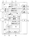
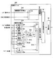
- FIG. 1 shows an electronic control unit (ECU) mounted on a vehicle, which controls the operation of an internal combustion engine mounted on the vehicle.
- the internal combustion engine according to the present embodiment is an ignition ignition gasoline engine, but may be a self-ignition diesel engine.
- the ECU 10 includes an MCU 11 (Micro Controller Unit), an ignition drive IC 12, a fuel injection valve drive IC 13, a throttle drive IC 14, a communication circuit 15, and an integrated IC 16.
- the MCU 11 includes a CPU 11a which is an arithmetic processing unit, a memory 11m which is a storage medium, an input processing circuit 11c, a communication circuit 11d, and a CPU check circuit 11e.
- the MCU 11 includes the CPU 11a, the memory 11m, the input processing circuit 11c, the communication circuit 11d, and the CPU check circuit 11e integrated on one semiconductor chip, but is dispersed and integrated on a plurality of semiconductor chips.
- a plurality of semiconductor chips may be mounted on a common substrate, or a semiconductor chip may be mounted on each of a plurality of substrates.
- each semiconductor chip may be housed in one common housing, or may be housed in separate housings.
- the memory 11 m is a storage medium for storing programs and data, and includes a non-transitional tangible storage medium for non-temporarily storing a program readable by the CPU 11 a.
- the storage medium may be provided by semiconductor memory or a magnetic disk or the like.
- the program stored in the memory 11m when executed by the CPU 11a, causes the ECU 10 to function as the device described in this specification and causes the control device to execute the method described in this specification.
- control device may be provided by software stored in a tangible storage medium and a computer executing the same, only software, only hardware, or a combination thereof.
- control device is provided by an electronic circuit that is hardware, it can be provided by a digital circuit or analog circuit that includes multiple logic circuits.
- the MCU 11 receives various signals such as an engine rotational speed, an accelerator opening degree, an intake manifold pressure, an exhaust pressure, a water temperature, an oil temperature, and an external signal output from an external ECU. These signals are input from the outside of the ECU 10 to the input processing circuit 11c or the communication circuit 11d.
- the engine speed signal is a signal representing the detected value of the crank angle sensor, and based on this detected value, the MCU 11 counts the rotational speed per unit time of the crankshaft (output shaft) of the internal combustion engine, that is, the rotational speed of the output shaft.
- the signal of the accelerator opening is a signal representing the detected value of the accelerator pedal sensor, and the MCU 11 calculates the amount of depression of the accelerator pedal operated by the driver of the vehicle, that is, the user of the internal combustion engine based on this detected value.
- the signal of the intake manifold pressure is a signal representing the detected value of the intake pressure sensor, and the MCU 11 calculates the pressure of the intake air taken into the combustion chamber based on this detected value.
- the exhaust pressure signal is a signal representing the detection value of the exhaust pressure sensor, and the MCU 11 calculates the pressure of the exhaust gas discharged from the combustion chamber based on this detection value.
- the water temperature signal is a signal that represents the detection value of the water temperature sensor, and the MCU 11 calculates the temperature of the water that cools the internal combustion engine based on this detection value.
- the oil temperature signal is a signal representing a detected value of the oil temperature sensor, and the MCU 11 calculates the temperature of the lubricating oil of the internal combustion engine or the hydraulic oil of the hydraulic actuator based on the detected value.
- a signal representing the operating state of an auxiliary device whose drive source is the output shaft of the internal combustion engine can be mentioned.
- the said auxiliary machine it is a refrigerant
- coolant compressor which the air conditioning apparatus which air-conditions a vehicle interior has, Comprising: The compressor which makes an output shaft of an internal combustion engine a drive source is mentioned.
- the ignition drive IC 12 has a switching element for controlling power supply and interruption to an ignition device provided in the internal combustion engine, and the MCU 11 outputs a command signal to the switching element. Specifically, the MCU 11 calculates a target ignition timing, which is a target value of the timing for performing discharge ignition by the ignition device, based on the various signals such as the engine rotation speed described above, and the command signal is calculated according to the calculated target ignition timing. Output to the ignition drive IC12.
- the fuel injection valve drive IC 13 has a switching element for controlling power supply and interruption to the fuel injection valve provided in the internal combustion engine, and the MCU 11 outputs a command signal to the switching element. Specifically, the MCU 11 calculates a target injection amount which is a target value of a period (that is, an injection amount) in which fuel injection is performed by the fuel injection valve based on various signals such as the engine rotation speed described above. The command signal is output to the fuel injection valve drive IC 13 in accordance with.
- the throttle drive IC 14 has a switching element for controlling power supply and disconnection to an electronic throttle valve (charge throttle) provided in the internal combustion engine, and the MCU 11 outputs a command signal to the switching element. Specifically, the MCU 11 calculates a target opening degree which is a target value of the valve opening degree of the screw based on the various signals such as the engine rotation speed described above, and generates a command signal according to the calculated target opening degree. It outputs to the slo drive IC 14.
- a target opening degree which is a target value of the valve opening degree of the screw based on the various signals such as the engine rotation speed described above
- the combustion state of the internal combustion engine is controlled by the ECU 10 controlling the operation of the ignition device, the fuel injection valve, and the throttle.
- the target ignition timing, the target injection amount and the target opening degree calculated by the MCU 11 correspond to a target control amount that is a target value of a control amount for controlling the combustion state of the internal combustion engine.
- the communication circuit 15 outputs various information held by the MCU 11 to the external ECU. For example, a signal of an abnormality flag representing that an abnormality such as a torque abnormality state occurs is output to a display ECU that controls the operation of a display device that the vehicle driver visually recognizes. The display ECU generates a warning display and a warning sound when acquiring the signal of the abnormality flag.
- the integrated IC 16 includes a memory (not shown), a CPU that executes various programs stored in the memory, and the like. Depending on the program executed by the CPU, the integrated IC 16 functions as the microcomputer monitoring unit 16a or functions as the flash cut control unit 16b.
- the CPU check circuit 11e checks whether the CPU 11a and the memory 11m are normal, such as executing a check (for example, parity check) whether the program and data stored in the memory 11m are normal.
- the microcomputer monitoring unit 16a monitors the operation failure of the MCU 11 while referring to the check result of the CPU check circuit 11e.
- the integrated IC 16 executes control of the electrocut, such as restricting the operation of the electrocut.
- control of the electrocut such as restricting the operation of the electrocut.
- the target opening degree is fixed to a predetermined opening degree set in advance, and the output of the internal combustion engine is limited so as to be less than the predetermined output.
- the target opening is made zero and the internal combustion engine is forcibly stopped.
- the throttle cut control unit 16 b outputs a signal for commanding the throttle cut to the throttle drive IC 14.
- the throttle drive IC 14 operates by giving priority to the throttle cut command signal over the command signal output from the MCU 11.
- the MCU 11 has a control module 20 and a monitoring module 30. Each of these modules is a function provided by the common CPU 11a and the memory 11m. That is, the CPU 11 a and the memory 11 m function as the control module 20 when the CPU 11 a is executing the control program stored in the control storage area 20 m of the memory 11 m.
- the CPU 11 a and the memory 11 m function as the monitoring module 30 when the CPU 11 a is executing the monitoring program stored in the monitoring storage area 30 m of the memory 11 m.
- the control storage area 20m and the monitoring storage area 30m are separately set in different areas of the storage area of the memory 11m.
- the control module 20 provides a “control arithmetic device” that calculates various target control amounts described above in accordance with a user request torque which is a drive torque of an internal combustion engine requested by a user.
- the monitoring module 30 monitors whether or not the estimated torque which is an estimated value of the actual torque of the internal combustion engine deviates by a predetermined amount or more from the engine required torque required for the internal combustion engine.
- a computing device is provided.
- the ECU 10 provides an internal combustion engine control system including a control computing device and a monitoring computing device.
- the control module 20 has functions as an engine required torque calculation unit 21 and a drive signal output unit 22.
- the engine required torque calculation unit 21 calculates an engine required torque, which is a torque to be required for the internal combustion engine, based on various signals acquired from the input processing circuit 11c and the communication circuit 11d.
- the drive signal output unit 22 calculates target control amounts such as the target ignition timing, the target injection amount, and the target opening degree described above in accordance with the engine request torque calculated by the engine request torque calculation unit 21. Furthermore, the drive signal output unit 22 outputs various command signals to the actuators such as the ignition drive IC 12, the fuel injection valve drive IC 13 and the throttle drive IC 14 according to the calculated target control amount.
- the engine required torque calculation unit 21 includes a user required torque calculation unit 21 a, a pump loss calculation unit 21 b, a friction loss calculation unit 21 c, a torque efficiency calculation unit 21 d, and calculation units B1 to B6. It has a function.
- the user request torque calculation unit 21a calculates a user request torque based on the engine speed and the accelerator opening degree described above.
- the user request torque is calculated to a larger value as the engine rotational speed is higher and as the accelerator opening degree is larger.
- a map representing the correlation between the engine rotational speed and the accelerator opening degree and the user request torque is stored in advance in the memory 11m, and the user request torque according to the engine rotational speed and the accelerator opening degree is referred to by referring to the map.
- the user request torque calculation unit 21a calculates.
- the pump loss calculating unit 21b calculates a pump loss torque, which is a value obtained by converting the pump loss into a torque, based on the above-described intake manifold pressure and exhaust pressure.
- Pump loss is energy loss due to resistance received from intake and exhaust when the piston of the internal combustion engine reciprocates. As the intake manifold pressure is lower, the pump loss is set to a larger value on the assumption that the intake resistance in the intake stroke of the piston is larger. Further, the pump loss is set to a large value, assuming that the exhaust resistance in the exhaust stroke of the piston is larger as the exhaust pressure is higher.
- a map representing the intake manifold pressure and the correlation between the exhaust pressure and the pump loss is stored in advance in the memory 11m, and the pump loss calculation unit 21b calculates the pump loss according to the intake manifold pressure and the exhaust pressure with reference to the map.
- the friction loss calculation unit 21c calculates friction loss torque which is a value obtained by converting the friction loss into torque based on the water temperature and the oil temperature described above.
- the friction loss is a mechanical energy loss due to the friction with the cylinder when the piston of the internal combustion engine reciprocates.
- the friction loss is set to a large value, assuming that the friction is large, as the water temperature is out of the proper range and becomes low or high. Further, the friction loss is set to a large value, assuming that the viscosity of the lubricating oil or the like is larger as the oil temperature is lower.
- a map representing the correlation between the water temperature and the oil temperature and the friction loss is stored in advance in the memory 11m, and the friction loss calculating unit 21c calculates the friction loss according to the water temperature and the oil temperature with reference to the map. .
- the calculation unit B1 calculates the total loss torque by adding the pump loss calculated by the pump loss calculation unit 21b, the friction loss calculated by the friction loss calculation unit 21c, and the loss torque learning value.
- the calculation unit B2 calculates the loss-included torque by adding the user request torque calculated by the user request torque calculation unit 21a, the total loss torque calculated by the calculation unit B1, and the external request torque.
- a specific example of the externally required torque is, for the purpose of charging the on-vehicle battery, a torque for an increase in power generation such as increasing the amount of power generation by a generator driven by an internal combustion engine.
- the calculation unit B3 calculates a reserve torque by adding a torque corresponding to each of the idle reserve, the catalyst warm-up reserve, and the auxiliary machine reserve. Each reserve torque is set by the control module 20 according to the operating state of the internal combustion engine such as the engine speed, the engine load, and the water temperature.
- the calculating unit B4 calculates the reserve included torque by adding the reserve torque calculated by the calculating unit B3 to the loss-included torque calculated by the calculating unit B2.
- the idle reserve torque is a torque corresponding to the amount of torque increase when performing control for increasing the torque at the time of idle operation of the internal combustion engine to stabilize the combustion.
- the catalyst warm-up reserve torque is the amount of combustion energy used to raise the exhaust gas temperature when performing warm-up control to raise the exhaust gas temperature to raise the temperature of the catalyst for purifying the exhaust gas of the internal combustion engine above the activation temperature. It is a value obtained by converting the loss into torque.
- the accessory reserve torque is a torque required to drive an accessory such as a generator whose drive source is an internal combustion engine.
- the torque efficiency calculation unit 21 d calculates the torque efficiency based on the maximum torque generation ignition timing (MBT ignition timing), the knock learning included base retardation amount and the target lambda.
- MBT ignition timing is an ignition timing at which the maximum torque can be obtained, and is different depending on the engine speed, the engine load, the water temperature, and the like.
- knocking is apt to occur at the MBT ignition timing, it is required to ignite at a timing that is a predetermined time later than the MBT ignition timing, that is, a timing at which the predetermined angle is retarded.
- the retarded timing is called base ignition timing.
- the retardation amount (base retardation amount) differs depending on the engine speed, the engine load, the water temperature, and the like.
- knock learning amount is used for the ignition timing from the next time on. Learning control to be reflected in control is called knock learning. Then, the timing at which the knocking learning amount is reflected in the base ignition timing corresponds to the target ignition timing.
- the calculation unit B5 calculates a timing obtained by subtracting the target ignition timing from the MBT ignition timing as an MBT retardation amount that is a retardation amount of the target ignition timing with respect to the MBT ignition timing.
- the torque efficiency calculation unit 21d calculates torque efficiency based on the MBT retardation amount calculated by the calculation unit B5 and the target lambda.
- the torque efficiency is the ratio of the energy to be converted to the rotational torque of the crankshaft among the combustion energy in the combustion chamber. As the MBT retardation amount is smaller, that is, as the target ignition timing is closer to the MBT ignition timing, the torque efficiency is calculated to a higher value.
- the target lambda is the target value of the ratio of air to fuel (lambda) included in the mixture that burns in the combustion chamber, and the torque efficiency calculator 21 d calculates torque efficiency to a value according to the target lambda. Do.
- a map representing the MBT retardation amount and the correlation between the target lambda and the torque efficiency is stored in advance in the memory 11m, and the torque efficiency corresponding to the MBT retardation amount and the target lambda is referred to as torque efficiency.
- the calculating unit 21d calculates.
- Each of the MBT ignition timing, the base ignition timing, and the target lambda described above is set by the control module 20 according to the operating state of the internal combustion engine such as the engine speed, the engine load, and the water temperature.
- the ECU 10 includes a detection circuit that detects the drive current or voltage output from the ignition drive IC. Then, the control module 20 calculates the engine required torque using the detected value by the detection circuit. Specifically, the actual ignition timing is calculated based on the detected value, and learning control relating to knock learning is executed using the actual ignition timing to calculate the knock learning amount.
- the calculation unit B6 divides the reserve torque calculated by the calculation unit B4 by the torque efficiency calculated by the torque efficiency calculation unit 21d to calculate an engine request torque for control used for engine control.
- the engine required torque calculation unit 21 calculates the engine required torque by dividing the value obtained by adding the total loss torque and the reserve torque to the user required torque by the torque efficiency.
- the monitoring module 30 monitors whether or not the estimated torque is in an abnormal torque state in which the estimated torque deviates from the engine required torque by a predetermined amount or more.
- the estimated torque is the actual torque of the internal combustion engine. It is the value which estimated
- the engine required torque is a torque required for the internal combustion engine, and is synonymous with the engine required torque calculated by the engine required torque calculation unit 21 of the control module 20.
- the engine request torque calculated by the monitoring module 30 is a value used to monitor torque abnormality
- the engine request torque calculated by the control module 20 is a value used to calculate a target control amount for the internal combustion engine. is there. That is, the engine required torque for monitoring and the engine required torque for control are values calculated in different areas of the storage area of the memory 11m.
- the monitoring module 30 has functions as an input securing unit 31, an engine required torque calculation unit 32, an estimated torque calculation unit 33, a torque comparison abnormality determination unit 34, and a throttle control unit 35.
- the input securing unit 31 checks that the data of various signals acquired from the input processing circuit 11c and the communication circuit 11d are normal (for example, parity check). If abnormal, the input securing unit 31 executes data restoration, data reacquisition, data discarding, and the like. Thereby, it can be avoided that the monitoring module 30 performs various calculations using the abnormal data. That is, the input securing unit 31 guarantees that various data used for calculation by the monitoring module 30 are normal.
- the torque comparison abnormality determination unit 34 calculates the difference between the period required torque calculated by the engine required torque calculation unit 32 and the estimated torque calculated by the estimated torque calculation unit 33, and if the difference is equal to or more than a predetermined value, It is determined that the torque abnormality state described above is present. If it is determined that the torque is in an abnormal state, the screw cut control unit 35 outputs a signal for commanding the screw cut to the screw drive IC 14 in the same manner as the screw cut control unit 16b.
- the engine required torque calculation unit 32 has functions as a catalyst warmup required torque calculation unit 32a, an idle required torque calculation unit 32b, and a calculation unit B11.
- the catalyst warm-up request torque calculation unit 32a calculates a catalyst warm-up request torque based on the catalyst warm-up target rotational speed and the accelerator opening degree described above.
- the warm-up control for raising the exhaust gas temperature to raise the temperature of the catalyst for purifying the exhaust gas of the internal combustion engine above the activation temperature is as described above, and the target value of the engine speed during the warm-up control is being performed. Is the catalyst warm-up target rotational speed.
- the catalyst warm-up request torque calculation unit 32a calculates the catalyst warm-up request torque based on the accelerator opening degree and the catalyst warm-up target rotational speed in the period in which the warm-up control is being performed.
- the catalyst warm-up request torque is synonymous with the catalyst warm-up reserve torque.
- the catalyst warm-up request torque calculated by the monitoring module 30 is a value used for monitoring a torque abnormality
- the catalyst warm-up reserve torque calculated by the control module 20 is used to calculate the target control amount for the internal combustion engine This is the value used. That is, the catalyst warm-up request torque for monitoring and the catalyst warm-up reserve torque for control are values calculated in different areas of the storage area of the memory 11 m.
- the catalyst warm-up target rotational speed and the accelerator opening are described as an example of variables used for calculation of the catalyst warm-up required torque, but the water temperature, the user request torque, the engine rotational speed and the intake are described as other variables.
- the filling efficiency can be mentioned.
- the intake charge efficiency is the ratio of the flow rate of the intake air compressed in the combustion chamber to the flow rate of the intake air that has passed through the throttle valve.
- the catalyst warm-up request torque calculation unit 32a calculates a catalyst warm-up request torque using at least one of these variables.
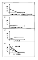
- the catalyst warm-up request torque (reserve amount) is calculated to be larger as the catalyst warm-up target rotational speed is larger when the accelerator pedal is not depressed. Further, as shown in (b), the catalyst warm-up request torque is set to a predetermined value if the accelerator opening degree when the accelerator pedal is depressed is less than a predetermined value, and is set to zero if it is equal to or more than the predetermined value. Also, as shown in (c) and (d), the catalyst warm-up request torque may be increased or decreased according to the water temperature or the engine rotational speed, and as shown in (d), the catalyst warm-up request torque according to the charging efficiency. You may increase or decrease the
- the idle required torque calculation unit 32 b calculates an idle required torque based on the idle target rotational speed and the above-described engine rotational speed.
- the idle control for increasing the torque at the time of idle operation of the internal combustion engine and stabilizing the combustion is as described above, and the target value of the engine speed during this idle control is the idle target speed. Then, the idle required torque calculation unit 32 b calculates the idle required torque based on the engine rotation speed and the idle target rotational speed during the period in which the idle control is being performed.
- the idle request torque is synonymous with the idle reserve torque.
- the idle required torque calculated by the monitoring module 30 is a value used to monitor torque abnormality
- the idle reserve torque calculated by the control module 20 is a value used to calculate a target control amount for the internal combustion engine. is there. That is, the idle request torque for monitoring and the idle reserve torque for control are values calculated in different areas of the storage area of the memory 11m.
- the idle target rotational speed and the engine rotational speed are described as an example of variables used to calculate the idle required torque, but other variables include water temperature, vehicle speed, atmospheric pressure and intake charge efficiency.
- the idle required torque calculation unit 32 b calculates an idle required torque using at least one of these variables.
- the idle required torque may be increased or decreased according to the water temperature or the engine rotational speed as shown in (c) (d), or in particular according to the filling efficiency as shown in (d) It is also good.
- the calculation unit B11 adds the catalyst warm-up request torque, the idle request torque, the user request torque, and the external request torque, which are calculated by the catalyst warm-up request torque calculation unit 32a and the idle request torque calculation unit 32b. Calculate the required engine torque required of the engine.
- the user request torque used for this calculation is calculated using data of the engine speed and the accelerator opening degree secured by the input securing unit 31.
- the engine required torque calculation unit 32 is various signals acquired from the input processing circuit 11c and the communication circuit 11d, and is requested to the internal combustion engine based on the signal (data) secured by the input guaranteeing unit 31. Calculate the engine request torque.
- the estimated torque calculation unit 33 includes an estimated torque calculation unit 33a, an MBT ignition timing calculation unit 33b, a base ignition timing calculation unit 33c, a torque efficiency calculation unit 33d, a loss torque calculation unit 33e, and calculation units B12 and B13. , B14.
- the estimated torque calculation unit 33a estimates the actual driving torque (MBT estimated torque) of the internal combustion engine when the ignition timing is MBT based on the above-described charging efficiency and engine speed.
- the MBT estimated torque is calculated to be a larger value as the engine speed is higher and as the filling efficiency is higher.
- a map representing the correlation between the engine rotational speed and the charging efficiency and the MBT estimated torque is stored in advance in the memory 11m, and the MBT estimated torque corresponding to the engine rotational speed and the charging efficiency is estimated torque by referring to the map
- the calculator 33a calculates.
- the MBT ignition timing calculation unit 33b calculates the MBT ignition timing based on the charging efficiency and the engine speed.
- the base ignition timing calculation unit 33c calculates the base ignition timing based on the charging efficiency and the engine speed.
- the MBT ignition timing and the base ignition timing are calculated with reference to the map stored in advance in the memory 11m, as in the estimated torque calculation unit 33a.
- the calculation unit B12 calculates a value obtained by subtracting the base ignition timing calculated by the base ignition timing calculation unit 33c from the MBT ignition timing calculated by the MBT ignition timing calculation unit 33b as the above-described base retardation amount.
- the torque efficiency calculation unit 33d calculates the above-described torque efficiency based on the base retardation amount calculated by the calculation unit B12. However, assuming that the knock learning amount is a predetermined amount or zero set in advance, the torque efficiency calculation unit 33 d calculates the torque efficiency.
- the loss torque calculation unit 33e calculates loss torque obtained by converting the loss energy including the pump loss and the friction loss into torque based on the engine rotation speed and the water temperature. For example, a map representing the correlation between the engine rotational speed and the water temperature and the loss torque is stored in advance in the memory 11m, and the loss torque calculation unit 33e calculates loss torque according to the engine rotational speed and the water temperature with reference to the map.
- the calculation unit B13 calculates a value obtained by multiplying the MBT estimated torque calculated by the estimated torque calculation unit 33a by the torque efficiency calculated by the torque efficiency calculation unit 33d as an estimated torque not considering the loss torque.
- the calculation unit B14 calculates a value obtained by subtracting the loss torque calculated by the loss torque calculation unit 33e from the estimated torque calculated by the calculation unit B13 as an estimated torque for monitoring.
- the estimated torque calculation unit 33 is various signals acquired from the input processing circuit 11c and the communication circuit 11d, and the internal combustion engine actually outputs based on the signal (data) secured by the input securing unit 31. Estimate the driving torque.
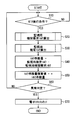
- the monitoring function by the monitoring module 30 is always operated. Specifically, the main process shown in FIG. 6 is always executed.
- the monitor execution condition For example, the completion of the check by the CPU check circuit 11e, the fact that the microcomputer monitoring unit 16a does not detect an abnormality, and the like are given as specific examples of the monitor execution condition.
- the engine required torque computing unit 32 calculates the engine required torque for monitoring in S20 according to the subroutine processing of FIG. In S30, the estimated torque calculation unit 33 calculates an estimated torque for monitoring in accordance with the subroutine processing of FIG.
- the torque comparison abnormality determination unit 34 performs abnormality determination. That is, first, at S40, the engine required torque calculated at S20 is subtracted from the estimated torque calculated at S30 to calculate a torque deviation amount. In the next S50, an integrated value is calculated by integrating the torque deviation amount calculated in S40 with the previous value. In the next S60, when the integrated value calculated in S50 is equal to or more than a predetermined amount, it is determined that a torque abnormality has occurred. The integrated value is reset, for example, when the internal combustion engine is stopped. If it is determined in S60 that the torque is abnormal, in S70, the screw cut control unit 35 outputs a screw cut command signal.
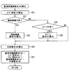
- the user requested torque is calculated.
- the calculation block of the user required torque is omitted in the engine required torque calculation unit 32 shown in FIG. 3, for example, the user required torque is calculated based on the engine speed and the accelerator opening in the same manner as the user required torque calculation unit 21a. Do. However, the user request torque is calculated using the data of the engine speed and the accelerator opening degree secured by the input securing unit 31.
- the catalyst warm-up request torque is based on at least one of catalyst warm-up target rotational speed, accelerator opening degree, water temperature, user request torque, engine speed and intake charging efficiency in S23.
- the calculation unit 32a calculates a catalyst warm-up request torque.
- the idle required torque calculation unit 32b calculates the idle required torque based on at least one of the idle target speed, the engine speed, the water temperature, the vehicle speed, the atmospheric pressure, and the intake charging efficiency in S25. calculate.
- an externally required torque which is a driving torque resulting from an external request such as an increase in the amount of generated power, is calculated.
- the user request torque in S21, the idle request torque in S25, the catalyst warm-up request torque in S23, and the external request torque in S26 are added. The added value is calculated as the engine required torque for monitoring.
- S25 If S25 is not executed, for example, if it is determined that warm-up control is under way in S22, the value of the most recently calculated idle required torque is used for the calculation of S27.
- S23 When S23 is not executed, if there is a catalyst warm-up request torque calculated most recently, that value is used for the calculation of S27.
- the estimated torque calculation unit 33a calculates the MBT estimated torque based on the engine speed and the charging efficiency.
- the MBT ignition timing calculation unit 33b calculates the MBT ignition timing based on the charging efficiency and the engine speed.
- the base ignition timing calculation unit 33c calculates the base ignition timing based on the charging efficiency and the engine speed.
- the torque efficiency calculation unit 33d calculates the ignition efficiency based on the value (base retardation amount) obtained by subtracting the base ignition timing calculated in S33 from the MBT ignition timing calculated in S32.
- the loss torque calculation unit 33e calculates the loss torque based on the engine speed and the water temperature.
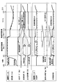
- the starter motor of the internal combustion engine is started at time t10 to start the operation of the internal combustion engine, and idle operation is performed from time t11 to time t14, and then traveling of the vehicle is started at time t14. .
- warm-up control is performed to achieve an early rise of the catalyst temperature in a period from t11 to t13.
- the idle operation is performed in the N range in which driving is not possible, and for the subsequent period from t12 to t13, the idle operation is performed in the d range doing.
- the upper part of FIG. 9 shows changes of various values calculated by the control module with respect to such transition of the operating state of the internal combustion engine, and the lower part of FIG. 9 shows various values of the various values calculated by the monitoring module. Indicates a change.
- the charging efficiency and the ignition retardation amount are controlled according to the idle reserve used in the calculation unit B3. Furthermore, when the idle reserve amount becomes zero at time t14, the ignition retardation amount and the charging efficiency are controlled based on the user request torque and the loss torque.
- the solid line in the column of the comparative example indicates the estimated torque calculated by the estimated torque calculation unit 33, and the dotted line indicates a user request torque used by the engine request torque calculation unit 32 to calculate the engine request torque.
- an erroneous monitoring result is obtained as follows.
- the engine required torque is calculated without reflecting the reserve torque, as shown by the arrow in the comparative example column
- the engine required torque calculated by the engine required torque calculating unit 32 and the estimated torque calculating unit 33 Discrepancies between the estimated torque and the estimated torque.
- the deviation is large even if the estimated torque is accurately calculated to a value close to the actual torque. Therefore, it is misjudged as torque abnormality.
- the catalyst warm-up request torque and the idle required torque are calculated by the catalyst warm-up required torque calculation unit 32a and the idle required torque calculation unit 32b. Then, since the engine request torque is calculated by adding the reserve torque calculated in this manner to the user request torque, as described in the section of this embodiment, the deviation between the engine request torque for monitoring and the estimated torque is suppressed. And the possibility of the above-mentioned erroneous determination is suppressed.
- the monitoring module 30 includes the engine required torque calculation unit 32 and the estimated torque calculation unit 33. Then, the engine required torque calculation unit 32 calculates, as reserve torque, a decrease in actual torque that occurs with the retardation of the ignition timing of the internal combustion engine, and calculates the engine required torque based on the calculated reserve torque and the user required torque. Therefore, the possibility of an erroneous determination as shown in the comparative example column of FIG. 9 can be suppressed, and torque abnormality can be monitored with high accuracy.
- the reserve torque is calculated and the monitoring engine request torque is calculated based on the calculated reserve torque and the user request torque. Therefore, the engine request torque can be calculated without using the detected value of the actual ignition timing. Since the detection cycle of this kind of detection value is short, if it is attempted to secure data by the input securing unit 31, the processing load of the input securing unit 31 becomes large. Moreover, the number of data input ports required of the input securing unit 31 increases by the amount of the detection value, which leads to an increase in cost of the input securing unit 31. Therefore, according to the present embodiment that can calculate the engine required torque without using the detected value of the actual ignition timing, it is possible to suppress the processing load on the monitoring module 30 and the cost increase.
- control module 20 sets the target ignition timing to be retarded at the time of catalyst warmup request, and the engine required torque calculation unit 32 performs combustion corresponding to the retarded amount of catalyst warmup request.
- the reserve torque is calculated to be equal to or more than the torque for the efficiency deterioration.
- control module 20 sets the target ignition timing to be retarded during idle operation, and the engine required torque calculation unit 32 reduces the combustion efficiency corresponding to the retarded amount of the idle required torque.
- the reserve torque is calculated to be equal to or higher than As described above, since the deterioration of the combustion efficiency caused by the retardation of the ignition timing such as the catalyst warm-up request and the idle request is reflected in the engine request torque for monitoring, the possibility of the above-mentioned erroneous determination can be suppressed.
- the reserve torque is reflected on the engine request torque calculated by the engine request torque calculation unit 32, and the estimated torque calculated by the estimated torque calculation unit 33 is corrected for the ignition timing by knock learning. It does not reflect the amount.
- the reserve torque is not reflected in the engine required torque calculated by the engine required torque computing unit 320.
- the correction amount of the ignition timing by knock learning that is, the knock learning amount described above is reflected in the estimated torque calculated by the estimated torque calculation unit 330.
- the calculation unit B110 of the engine required torque calculation unit 320 calculates the engine required torque by adding the externally required torque to the user requested torque.
- the estimated torque calculation unit 330 has a knock learning amount calculation unit 330 c and a calculation unit B 120 in addition to the various calculation units included in the estimated torque calculation unit 33 shown in FIG. 3.
- the knock learning amount calculation unit 330c calculates the knock learning amount described above based on the charging efficiency and the engine speed. For example, a map representing the correlation between the engine speed and the filling efficiency and the knocking learning amount is stored in advance in the memory 11m, and the knocking learning amount according to the engine speed and the filling efficiency is knocked with reference to the map The learning amount calculation unit 330 c calculates. It should be noted that the knocking learning amount may be calculated using the intake amount instead of the charging efficiency. In short, the knocking learning amount can be accurately calculated by using the physical quantity and the engine rotational speed correlated with the intake amount.
- the calculation unit B120 subtracts the knock learning amount calculated by the knock learning amount calculation unit 330c from the base ignition timing calculated by the base ignition timing calculation unit 33c, that is, at the target ignition timing calculated by the control module 20. Calculate the corresponding time.
- the calculation unit B12 calculates a value obtained by subtracting the target ignition timing calculated by the knock learning amount calculation unit 330c from the MBT ignition timing calculated by the MBT ignition timing calculation unit 33b as a knock-in base retardation amount.
- the knock-in base retardation amount corresponds to a value obtained by adding the knock learning amount to the base retardation amount.
- the torque efficiency calculation unit 33 d calculates the torque efficiency described above based on the knocked-on base retardation amount calculated by the calculation unit B12.
- the user request torque is calculated, and at S26, an external request torque which is a driving torque resulting from an external request such as an increase in the generated power amount is calculated.
- an external request torque which is a driving torque resulting from an external request such as an increase in the generated power amount is calculated.
- the user request torque in S21 and the external request torque in S26 are added. The added value is calculated as the engine required torque for monitoring.
- the MBT estimated torque is calculated in S31
- the MBT ignition timing is calculated in S32
- the base ignition timing is calculated in S33.
- the knock learning amount calculation unit 330c calculates a knock learning amount based on the charging efficiency and the engine speed.
- a timing is calculated by subtracting the knocking learning amount calculated at S33A from the base ignition timing calculated at S33. This timing corresponds to the estimated value of the actual ignition timing (estimated ignition timing). Further, in S34, a knock-in base retardation amount is calculated by subtracting the estimated ignition timing from the MBT ignition timing calculated in S32.
- the loss torque is calculated in S35, the MBT estimated torque is multiplied by the ignition efficiency in S36, and the loss torque is subtracted from the multiplication value to calculate the estimated torque for monitoring.
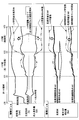
- the starter motor of the internal combustion engine is started at time t20 to start the operation of the internal combustion engine.
- the rotational speed changes in a region where knock does not occur (non-knock region) until time t21 thereafter.
- time t22 thereafter the rotational speed increases and shifts in a region where knocking occurs (low and medium load knock region).
- time t23 thereafter the rotational speed increases and remains in a region where knocking is more likely to occur (high load knock region).
- the upper part of FIG. 13 shows changes in various values calculated by the control module with respect to the transition of the operating state of the internal combustion engine, and the lower part of FIG. 13 shows various values of the various values calculated by the monitoring module. Indicates a change.
- the knock learning amount is zero in the non-knocked area period (t20 to t21) and increases in the subsequent low and medium load knocked area. There is a further increase in the area. Then, the ignition timing changes from the value shown by the solid line to the value shown by the alternate long and short dash line with the increase of the knock learning amount, that is, shifts to the retard side. Further, due to the decrease in torque efficiency due to the retardation of the ignition timing, the filling efficiency changes from the value shown by the solid line to the value shown by the two-dot chain line.
- the solid line in the column of the comparative example indicates the estimated torque calculated by the estimated torque calculation unit 330 and the engine required torque calculated by the engine required torque calculation unit 320 when knock learning is not performed. Both of these torques match if knock learning is not performed. Contrary to the present embodiment, when the estimated torque calculation unit 330 does not have the knock learning amount calculation unit 330c, as indicated by the two-dot chain line in the comparative example column, the estimated torque corresponds to the increase in the air amount. Will increase. As a result, false monitoring results as follows.
- the estimated torque can be made close to the required torque as shown by the dotted line in the column of the required torque correction amount. The reason why the estimated torque does not completely match the required torque will be described below.
- the estimated torque calculation unit 330 does not necessarily detect the actual ignition timing to estimate the torque efficiency, and the knock learning amount calculation unit 330 c estimates the knock learning amount from the engine speed and the filling efficiency, and the estimation thereof The torque efficiency is estimated from the value. Therefore, it is difficult to estimate according to the fuel being used.
- the knock learning amount calculation unit 330 c estimates the knock learning amount by regarding the fuel intermediate between the fuel with the highest octane number and the fuel with the lowest octane number among the assumed fuels as the used fuel.
- the dashed-two dotted line described in the column of the required torque correction amount in FIG. 13 is the estimated torque after knock learning when the lowest octane fuel is used, and the dashed dotted line is the knock learning when the highest octane fuel is used It is a later estimated torque.
- the estimated torque calculated by the estimated torque calculator 330 according to the present embodiment is a value indicated by a dotted line, and is an intermediate value between the lowest octane number and the highest octane number. As described above, since the estimated torque according to the present embodiment is brought close to the required torque, the deviation between the engine required torque for monitoring and the estimated torque is suppressed, and the possibility of the above-described erroneous determination is suppressed.
- the monitoring module 300 includes the engine required torque calculation unit 320 that calculates the engine required torque, and the estimated torque calculation unit 330 that calculates the estimated torque.
- the estimated torque calculation unit 330 calculates the actual ignition timing based on the operating state of the internal combustion engine, such as the engine rotational speed and the intake amount to the internal combustion engine, and estimates the torque efficiency based on the calculated actual ignition timing. It can be said. Further, the estimated torque calculation unit 330 calculates an estimated torque based on the estimated torque efficiency. In detail, it can be said that the estimated torque calculation unit 330 calculates the estimated torque based on the deterioration of the torque efficiency corresponding to the knock learning amount based on the engine speed and the intake amount. Therefore, the possibility of an erroneous determination as shown in the comparative example column of FIG. 13 can be suppressed, and torque abnormality can be monitored with high accuracy.
- the estimated torque can be calculated without using the detected value of the actual ignition timing. Since the detection cycle of this kind of detection value is short, if it is attempted to secure data by the input securing unit 31, the processing load of the input securing unit 31 becomes large. Moreover, the number of data input ports required of the input securing unit 31 increases by the amount of the detection value, which leads to an increase in cost of the input securing unit 31. Therefore, according to the present embodiment that can calculate the estimated torque without using the detected value of the actual ignition timing, it is possible to suppress the processing load on the monitoring module 300 and the cost increase.
- the present inventor has confirmed the following events by a test or the like. That is, at the normal time when no torque abnormality occurs, the engine required torque reflecting the reserve torque is highly correlated with the estimated torque not reflecting the knock learning, and the difference is small. In addition, at the normal time when no torque abnormality occurs, the engine required torque not reflecting the reserve torque is highly correlated with the estimated torque reflecting the knock learning and the deviation becomes small. In short, it can be said that the torque reduction amount corresponding to the torque efficiency deterioration due to the ignition retardation by knock learning corresponds to the reserve torque.
- the internal combustion engine control system according to the present embodiment is a modification of the first embodiment, and the configuration which is not particularly mentioned is the same as the first embodiment.
- the data used for the calculation of the monitoring module 30, 300 is data (external data) transmitted from the input processing circuit 11c and the communication circuit 11d.
- data (internal data) which is the calculation result of the control module 201 is used for the calculation of the monitoring module 301.
- the control module 201 has a configuration in which a reserve torque calculation unit 23 is added to the control module 20 shown in FIG.
- the reserve torque calculation unit 23 calculates a reserve torque obtained by converting the combustion efficiency deterioration portion not converted into the drive torque among the combustion energy of the internal combustion engine into a torque.
- the reserve torque includes at least one of the idle reserve, the catalyst warm-up reserve and the accessory reserve shown in FIG.
- the calculation unit B3 adds the reserve torques calculated by the reserve torque calculation unit 23 and outputs the sum to the calculation unit B4.
- the drive signal output unit 22 also functions as an ignition timing control unit that sets a target ignition timing.
- the drive signal output unit 22 as an ignition timing control unit adds the reserve torque calculated by the reserve torque calculation unit 23 to the user request torque, and sets a target ignition timing based on the added torque.
- the input securing unit 311 of the monitoring module 301 acquires internal data in addition to external data, and checks that the internal data is normal (for example, parity check).
- the internal data acquired by the input securing unit 311 includes reserve torque, and the monitoring module 301 when acquiring the internal data corresponds to a reserve torque acquisition unit. Further, when the reserve torque value output from the control module 201 exceeds the predetermined range, the input securing unit 311 as the reserve torque acquisition unit reserves a value obtained by limiting the upper limit torque or the lower limit torque to the reserve torque value. Get as.
- the engine required torque calculation unit 321 calculates an engine required torque based on the reserve torque (internal data) acquired by the input securing unit 311 and the user required torque (external data). More specifically, the catalyst warm-up request torque calculation unit 32a and the idle request torque calculation unit 32b according to the first embodiment calculate the catalyst warm-up request torque and the idle request torque based on external data such as the target rotation speed. doing. On the other hand, in the present embodiment, the catalyst warm-up request torque calculation unit 32a and the idle request torque calculation unit 32b are eliminated, and the value of the reserve torque acquired by the input securing unit 311 is directly input to the operation unit B11. There is.
- the engine required torque calculation unit 321 calculates the engine required torque using the reserve torque value calculated by the control module 201. Therefore, the calculation accuracy of the engine required torque can be improved as compared to the case where the reserve torque value calculated from the external data is used.
- the reserve torque value exceeds the predetermined range, the upper limit torque or the lower limit torque is limited. Therefore, even if the control module 201 has a failure and the control module 201 calculates an inappropriate reserve torque value, monitoring of torque abnormality using an inappropriate reserve torque value is suppressed. Therefore, the deterioration of the monitoring accuracy caused by the failure of the control module 201 can be suppressed.
- the internal combustion engine control system according to the present embodiment is a modification of the second embodiment, and the configuration which is not particularly mentioned is the same as the second embodiment.
- data which is the calculation result of the control module 202 is used for the calculation of the monitoring module 302 as in the third embodiment. .
- the control module 202 is configured such that the knock learning amount calculation unit 24 is added to the control module 20 shown in FIG. 2, and the calculation content of the calculation unit B5 is changed as follows.
- the knock learning amount calculation unit 24 calculates a knock learning amount which is an amount for correcting the ignition timing according to the presence or absence of knocking in the internal combustion engine. Specifically, the ignition timing is retarded each time knock occurs, and the correction amount is calculated so as to advance the angle if knock does not occur.
- the calculation unit B5 according to the present embodiment calculates a timing (target ignition timing) at which the knocking learning amount calculated by the knocking learning amount calculation unit 24 is retarded from the base ignition timing.
- the calculation unit B5 calculates a timing obtained by subtracting the target ignition timing from the MBT ignition timing as an MBT retardation amount that is a retardation amount of the target ignition timing with respect to the MBT ignition timing.
- the drive signal output unit 22 as an ignition timing control unit sets, as a target ignition timing, a timing obtained by retarding the knocking learning amount calculated by the knocking learning amount calculating unit 24 from the base ignition timing.
- the input securing unit 312 included in the monitoring module 302 acquires internal data in addition to external data, and checks that the internal data is normal (for example, parity check).
- the internal data acquired by the input securing unit 312 includes a knock learning amount, and the monitoring module 302 when acquiring the internal data corresponds to a retardation amount acquiring unit. Further, when the value of the knock learning amount output from the control module 202 exceeds the predetermined range, the input securing unit 312 as the retardation amount acquisition unit limits the upper limit retardation amount or the lower limit retardation amount. The obtained value is acquired as the knocking learning amount.
- the estimated torque calculation unit 331 calculates an estimated torque based on the knocking learning amount (internal data) acquired by the input securing unit 312 and the operating state of the internal combustion engine (external data). More specifically, in the second embodiment, the knock learning amount calculation unit 330 c calculates the knock learning amount based on the external data such as the target number of revolutions, and the torque efficiency calculation unit 33 d uses the calculated knock learning amount. Torque efficiency is calculated. On the other hand, in the present embodiment, the knock learning amount calculation unit 330 c is eliminated, and the knock learning amount acquired by the input securing unit 312 is directly input to the calculation unit B 120.
- the estimated torque calculation unit 331 calculates the estimated torque using the knock learning amount calculated by the control module 202, compared to the case where the knock learning amount calculated from the external data is used.
- the calculation accuracy of the estimated torque can be improved.
- the knock learning amount exceeds the predetermined range, the upper limit retardation amount or the lower limit retardation amount is limited. Therefore, even if the control module 202 has a failure and the control module 202 calculates an inappropriate amount of knock learning, monitoring of torque abnormality using an inappropriate amount of knock learning is suppressed. Therefore, the deterioration of the monitoring accuracy caused by the failure of the control module 202 can be suppressed.
- the disclosure in this specification is not limited to the illustrated embodiments.
- the disclosure includes the illustrated embodiments and variations based on them by those skilled in the art.
- the disclosure is not limited to the combination of parts and / or elements shown in the embodiments.
- the disclosure can be implemented in various combinations.
- the disclosure can have additional parts that can be added to the embodiments.
- the disclosure includes those in which parts and / or elements of the embodiments have been omitted.
- the disclosure includes replacements or combinations of parts and / or elements between one embodiment and another embodiment.
- the disclosed technical scope is not limited to the description of the embodiments. It is to be understood that the technical scopes disclosed herein are indicated by the description of the scope of the claims, and further include all modifications within the meaning and scope equivalent to the descriptions of the scope of the claims.
- the influence of the actual ignition timing is reflected in the calculation of the engine required torque.
- the reserve torque is calculated, the engine required torque is calculated using the calculated value, and it can be said that the calculated value of the reserve torque is reflected in the calculation of the engine required torque.
- the calculated value of reserve torque may be reflected in the calculation of estimated torque.
- the influence of the actual ignition timing is reflected in the calculation of the estimated torque.
- the knock learning amount is calculated, and the estimated torque is calculated using the calculated value, and it can be said that the calculated value of the knock learning amount is reflected in the calculation of the estimated torque.
- the calculated value of the knocking learning amount may be reflected in the calculation of the engine required torque.
- the calculation speed of the monitoring module 30 is slower than the calculation speed of the control module 20. Specifically, the check processing speed by the input securing unit 31 becomes a bottleneck, and the calculation speed of the engine required torque calculation unit 32 and the estimated torque calculation unit 33 is slower than the calculation speed of the engine required torque calculation unit 21 . On the other hand, the calculation speed of the monitoring module 30 may be equal to the calculation speed of the control module 20.
- control storage area 20m and the monitoring storage area 30m are set in the storage area of one common memory 11m.
- a plurality of memories may be provided in the ECU 10, the storage area of the first memory may be set as the control storage area, and the storage area of the second memory may be set as the monitoring storage area.
- one common MCU 11 has the control storage area 20m and the monitoring storage area 30m.
- the ECU 10 may be provided with a plurality of MCUs, the first MCU may have a control storage area, and the second MCU may have a monitoring storage area.
- the ECU 10 is provided with a detection circuit for detecting the drive current or voltage output from the ignition drive IC, and the control modules 20, 201, 202 perform knock learning using the detection value by the detection circuit. Control is being performed.
- the command signal output from the drive signal output unit 22 to the ignition drive IC 12 may be regarded as the actual ignition timing, and knock learning control may be performed without using the detected value.
- the calculation unit B3 shown in FIG. 2 adds each of the idle reserve, the catalyst warm-up reserve, and the accessory reserve to calculate reserve torque and outputs the reserve torque to the calculation unit B4.
- the maximum value of the idle reserve, the catalyst warm-up reserve, and the auxiliary machine reserve may be calculated as the reserve torque and may be output to the calculation unit B4.
- all of the idle reserve, the catalyst warm-up reserve, and the auxiliary machine reserve are used to calculate the reserve torque, but at least one of these reserves may be used to calculate the reserve torque.
- the engine request torque is calculated by adding both the catalyst warm-up request torque and the idle request torque to the user request torque.
- the engine request torque may be calculated by adding the request torque having the larger value of the catalyst warm-up request torque and the idle request torque to the user request torque.
- the control module 20 shown in FIG. 2 may be provided with the reserve torque calculation unit 23 shown in FIG. 14 and the knock learning amount calculation unit 24 shown in FIG.
- the internal combustion engine mounted on the vehicle is the control target of the ECU 10, but a stationary internal combustion engine other than the on-vehicle may be the control target of the ECU 10.
Landscapes
- Engineering & Computer Science (AREA)
- Chemical & Material Sciences (AREA)
- Combustion & Propulsion (AREA)
- Mechanical Engineering (AREA)
- General Engineering & Computer Science (AREA)
- Combined Controls Of Internal Combustion Engines (AREA)
- Electrical Control Of Ignition Timing (AREA)
Priority Applications (2)
| Application Number | Priority Date | Filing Date | Title |
|---|---|---|---|
| DE112018003865.3T DE112018003865B4 (de) | 2017-07-28 | 2018-06-26 | Steuersystem einer Maschine mit interner Verbrennung |
| US16/751,800 US10907555B2 (en) | 2017-07-28 | 2020-01-24 | Internal combustion engine control system |
Applications Claiming Priority (2)
| Application Number | Priority Date | Filing Date | Title |
|---|---|---|---|
| JP2017-146907 | 2017-07-28 | ||
| JP2017146907A JP6717271B2 (ja) | 2017-07-28 | 2017-07-28 | 内燃機関制御システム |
Related Child Applications (1)
| Application Number | Title | Priority Date | Filing Date |
|---|---|---|---|
| US16/751,800 Continuation US10907555B2 (en) | 2017-07-28 | 2020-01-24 | Internal combustion engine control system |
Publications (1)
| Publication Number | Publication Date |
|---|---|
| WO2019021721A1 true WO2019021721A1 (ja) | 2019-01-31 |
Family
ID=65040785
Family Applications (1)
| Application Number | Title | Priority Date | Filing Date |
|---|---|---|---|
| PCT/JP2018/024216 Ceased WO2019021721A1 (ja) | 2017-07-28 | 2018-06-26 | 内燃機関制御システム |
Country Status (4)
| Country | Link |
|---|---|
| US (1) | US10907555B2 (https=) |
| JP (1) | JP6717271B2 (https=) |
| DE (1) | DE112018003865B4 (https=) |
| WO (1) | WO2019021721A1 (https=) |
Cited By (4)
| Publication number | Priority date | Publication date | Assignee | Title |
|---|---|---|---|---|
| US11008961B2 (en) | 2017-07-28 | 2021-05-18 | Denso Corporation | Internal combustion engine control system |
| US11028793B2 (en) | 2017-08-30 | 2021-06-08 | Denso Corporation | Internal combustion engine control system |
| US11149598B2 (en) | 2017-07-28 | 2021-10-19 | Denso Corporation | Fuel injection control device and fuel injection control method |
| US11313306B2 (en) | 2017-08-01 | 2022-04-26 | Denso Corporation | Torque monitoring device |
Families Citing this family (6)
| Publication number | Priority date | Publication date | Assignee | Title |
|---|---|---|---|---|
| GB2584427B (en) * | 2019-05-29 | 2021-11-10 | Jaguar Land Rover Ltd | Controller for a vehicle internal combustion engine |
| JP7096852B2 (ja) * | 2020-02-25 | 2022-07-06 | 本田技研工業株式会社 | エンジン制御装置 |
| JP7351259B2 (ja) * | 2020-06-08 | 2023-09-27 | トヨタ自動車株式会社 | 車両の制御装置 |
| CN111946527B (zh) * | 2020-07-31 | 2021-10-15 | 东风汽车集团有限公司 | 汽油机火路扭矩效率确定方法和实际点火效率确定方法 |
| CN113294258B (zh) * | 2021-05-13 | 2023-02-17 | 上海新动力汽车科技股份有限公司 | 基于动态负荷的发动机恒转速控制方法 |
| JP2025033599A (ja) * | 2023-08-30 | 2025-03-13 | トヨタ自動車株式会社 | 車両の異常判定装置 |
Citations (5)
| Publication number | Priority date | Publication date | Assignee | Title |
|---|---|---|---|---|
| JP2010043536A (ja) * | 2008-08-08 | 2010-02-25 | Denso Corp | 車両の制御装置 |
| JP2011032903A (ja) * | 2009-07-30 | 2011-02-17 | Denso Corp | 車両の制御装置 |
| JP2011052696A (ja) * | 2010-12-14 | 2011-03-17 | Denso Corp | 内燃機関の監視装置 |
| JP2014173535A (ja) * | 2013-03-11 | 2014-09-22 | Nissan Motor Co Ltd | 内燃機関の制御装置及び内燃機関の制御方法 |
| JP2016098786A (ja) * | 2014-11-26 | 2016-05-30 | トヨタ自動車株式会社 | 内燃機関の制御装置 |
Family Cites Families (8)
| Publication number | Priority date | Publication date | Assignee | Title |
|---|---|---|---|---|
| DE10210684B4 (de) | 2002-03-12 | 2005-04-14 | Robert Bosch Gmbh | Verfahren und Vorrichtung zur Überwachung eines Moments einer Antriebseinheit eines Fahrzeugs |
| JP2004278461A (ja) * | 2003-03-18 | 2004-10-07 | Toyota Motor Corp | 内燃機関のノッキング制御装置 |
| JP2008064032A (ja) * | 2006-09-07 | 2008-03-21 | Toyota Motor Corp | 内燃機関の制御装置、制御方法、その方法を実現するプログラムおよびそのプログラムを記録した記録媒体 |
| DE102007031769B4 (de) | 2007-07-07 | 2009-07-16 | Dr. Ing. H.C. F. Porsche Aktiengesellschaft | Verfahren zur Überwachung eines Funktionsrechners in einem Steuergerät |
| JP6780600B2 (ja) | 2017-07-28 | 2020-11-04 | 株式会社デンソー | 内燃機関制御システム |
| JP6809408B2 (ja) | 2017-08-01 | 2021-01-06 | 株式会社デンソー | トルク監視装置および内燃機関制御システム |
| JP6661593B2 (ja) * | 2017-12-05 | 2020-03-11 | 本田技研工業株式会社 | 内燃機関の制御装置 |
| US10974714B2 (en) * | 2019-01-17 | 2021-04-13 | Ford Global Technologies, Llc | Method and system for torque reserve estimation |
-
2017
- 2017-07-28 JP JP2017146907A patent/JP6717271B2/ja active Active
-
2018
- 2018-06-26 DE DE112018003865.3T patent/DE112018003865B4/de active Active
- 2018-06-26 WO PCT/JP2018/024216 patent/WO2019021721A1/ja not_active Ceased
-
2020
- 2020-01-24 US US16/751,800 patent/US10907555B2/en active Active
Patent Citations (5)
| Publication number | Priority date | Publication date | Assignee | Title |
|---|---|---|---|---|
| JP2010043536A (ja) * | 2008-08-08 | 2010-02-25 | Denso Corp | 車両の制御装置 |
| JP2011032903A (ja) * | 2009-07-30 | 2011-02-17 | Denso Corp | 車両の制御装置 |
| JP2011052696A (ja) * | 2010-12-14 | 2011-03-17 | Denso Corp | 内燃機関の監視装置 |
| JP2014173535A (ja) * | 2013-03-11 | 2014-09-22 | Nissan Motor Co Ltd | 内燃機関の制御装置及び内燃機関の制御方法 |
| JP2016098786A (ja) * | 2014-11-26 | 2016-05-30 | トヨタ自動車株式会社 | 内燃機関の制御装置 |
Cited By (4)
| Publication number | Priority date | Publication date | Assignee | Title |
|---|---|---|---|---|
| US11008961B2 (en) | 2017-07-28 | 2021-05-18 | Denso Corporation | Internal combustion engine control system |
| US11149598B2 (en) | 2017-07-28 | 2021-10-19 | Denso Corporation | Fuel injection control device and fuel injection control method |
| US11313306B2 (en) | 2017-08-01 | 2022-04-26 | Denso Corporation | Torque monitoring device |
| US11028793B2 (en) | 2017-08-30 | 2021-06-08 | Denso Corporation | Internal combustion engine control system |
Also Published As
| Publication number | Publication date |
|---|---|
| US20200158034A1 (en) | 2020-05-21 |
| US10907555B2 (en) | 2021-02-02 |
| JP2019027349A (ja) | 2019-02-21 |
| DE112018003865B4 (de) | 2023-09-21 |
| DE112018003865T5 (de) | 2020-04-09 |
| JP6717271B2 (ja) | 2020-07-01 |
Similar Documents
| Publication | Publication Date | Title |
|---|---|---|
| JP6717271B2 (ja) | 内燃機関制御システム | |
| WO2019026545A1 (ja) | トルク監視装置および内燃機関制御システム | |
| JP6780600B2 (ja) | 内燃機関制御システム | |
| US10696293B2 (en) | Start controller and start controlling method | |
| CN102124201A (zh) | 内燃机的控制装置 | |
| JP5158228B2 (ja) | 内燃機関制御装置 | |
| JP6809415B2 (ja) | 内燃機関制御システム | |
| US9638123B2 (en) | Internal combustion engine controller | |
| US10273929B2 (en) | Ignition timing control apparatus for internal combustion engine | |
| US20140222316A1 (en) | Control apparatus and control method for internal combustion engine | |
| US11118527B2 (en) | Internal combustion engine control system | |
| US20190277210A1 (en) | Control device for internal combustion engine | |
| JP2009097347A (ja) | 内燃機関の制御装置 | |
| JP7067078B2 (ja) | 内燃機関制御システム | |
| CN107917003B (zh) | 一种发动机运转平稳性的控制方法 | |
| JP2019094873A (ja) | 内燃機関制御システム | |
| JP4251028B2 (ja) | 内燃機関の制御装置 | |
| JP2008190499A (ja) | 内燃機関の制御装置、制御方法およびその方法をコンピュータで実現されるプログラムならびにそのプログラムを記録した記録媒体 | |
| WO2014141598A1 (ja) | 筒内噴射式内燃機関の燃料噴射制御装置 | |
| JP2013204553A (ja) | 内燃機関の統合制御装置 | |
| JP5868075B2 (ja) | 発電機の制御装置 | |
| JP2007046573A (ja) | 内燃機関の制御装置 | |
| JP2007170198A (ja) | 内燃機関のトルク制御装置 |
Legal Events
| Date | Code | Title | Description |
|---|---|---|---|
| 121 | Ep: the epo has been informed by wipo that ep was designated in this application |
Ref document number: 18839080 Country of ref document: EP Kind code of ref document: A1 |
|
| 122 | Ep: pct application non-entry in european phase |
Ref document number: 18839080 Country of ref document: EP Kind code of ref document: A1 |