WO2019017434A1 - 超音波振動付与装置 - Google Patents
超音波振動付与装置 Download PDFInfo
- Publication number
- WO2019017434A1 WO2019017434A1 PCT/JP2018/027103 JP2018027103W WO2019017434A1 WO 2019017434 A1 WO2019017434 A1 WO 2019017434A1 JP 2018027103 W JP2018027103 W JP 2018027103W WO 2019017434 A1 WO2019017434 A1 WO 2019017434A1
- Authority
- WO
- WIPO (PCT)
- Prior art keywords
- ultrasonic wave
- container
- unit
- wave generator
- fitting
- Prior art date
- Legal status (The legal status is an assumption and is not a legal conclusion. Google has not performed a legal analysis and makes no representation as to the accuracy of the status listed.)
- Ceased
Links
Images












Classifications
-
- B—PERFORMING OPERATIONS; TRANSPORTING
- B67—OPENING, CLOSING OR CLEANING BOTTLES, JARS OR SIMILAR CONTAINERS; LIQUID HANDLING
- B67D—DISPENSING, DELIVERING OR TRANSFERRING LIQUIDS, NOT OTHERWISE PROVIDED FOR
- B67D1/00—Apparatus or devices for dispensing beverages on draught
- B67D1/08—Details
- B67D1/12—Flow or pressure control devices or systems, e.g. valves, gas pressure control, level control in storage containers
- B67D1/14—Reducing valves or control taps
- B67D1/1405—Control taps
- B67D1/1411—Means for controlling the build-up of foam in the container to be filled
- B67D1/1416—Means for controlling the build-up of foam in the container to be filled comprising foam inducing means
-
- A—HUMAN NECESSITIES
- A47—FURNITURE; DOMESTIC ARTICLES OR APPLIANCES; COFFEE MILLS; SPICE MILLS; SUCTION CLEANERS IN GENERAL
- A47J—KITCHEN EQUIPMENT; COFFEE MILLS; SPICE MILLS; APPARATUS FOR MAKING BEVERAGES
- A47J43/00—Implements for preparing or holding food, not provided for in other groups of this subclass
- A47J43/04—Machines for domestic use not covered elsewhere, e.g. for grinding, mixing, stirring, kneading, emulsifying, whipping or beating foodstuffs, e.g. power-driven
- A47J43/07—Parts or details, e.g. mixing tools, whipping tools
-
- B—PERFORMING OPERATIONS; TRANSPORTING
- B06—GENERATING OR TRANSMITTING MECHANICAL VIBRATIONS IN GENERAL
- B06B—METHODS OR APPARATUS FOR GENERATING OR TRANSMITTING MECHANICAL VIBRATIONS OF INFRASONIC, SONIC, OR ULTRASONIC FREQUENCY, e.g. FOR PERFORMING MECHANICAL WORK IN GENERAL
- B06B1/00—Methods or apparatus for generating mechanical vibrations of infrasonic, sonic, or ultrasonic frequency
- B06B1/02—Methods or apparatus for generating mechanical vibrations of infrasonic, sonic, or ultrasonic frequency making use of electrical energy
- B06B1/0207—Driving circuits
-
- B—PERFORMING OPERATIONS; TRANSPORTING
- B67—OPENING, CLOSING OR CLEANING BOTTLES, JARS OR SIMILAR CONTAINERS; LIQUID HANDLING
- B67D—DISPENSING, DELIVERING OR TRANSFERRING LIQUIDS, NOT OTHERWISE PROVIDED FOR
- B67D1/00—Apparatus or devices for dispensing beverages on draught
- B67D1/08—Details
-
- B—PERFORMING OPERATIONS; TRANSPORTING
- B67—OPENING, CLOSING OR CLEANING BOTTLES, JARS OR SIMILAR CONTAINERS; LIQUID HANDLING
- B67D—DISPENSING, DELIVERING OR TRANSFERRING LIQUIDS, NOT OTHERWISE PROVIDED FOR
- B67D1/00—Apparatus or devices for dispensing beverages on draught
- B67D1/08—Details
- B67D1/12—Flow or pressure control devices or systems, e.g. valves, gas pressure control, level control in storage containers
- B67D1/127—Froth control
- B67D1/1275—Froth control promoting froth
-
- C—CHEMISTRY; METALLURGY
- C12—BIOCHEMISTRY; BEER; SPIRITS; WINE; VINEGAR; MICROBIOLOGY; ENZYMOLOGY; MUTATION OR GENETIC ENGINEERING
- C12H—PASTEURISATION, STERILISATION, PRESERVATION, PURIFICATION, CLARIFICATION OR AGEING OF ALCOHOLIC BEVERAGES; METHODS FOR ALTERING THE ALCOHOL CONTENT OF FERMENTED SOLUTIONS OR ALCOHOLIC BEVERAGES
- C12H1/00—Pasteurisation, sterilisation, preservation, purification, clarification, or ageing of alcoholic beverages
- C12H1/12—Pasteurisation, sterilisation, preservation, purification, clarification, or ageing of alcoholic beverages without precipitation
- C12H1/16—Pasteurisation, sterilisation, preservation, purification, clarification, or ageing of alcoholic beverages without precipitation by physical means, e.g. irradiation
Definitions
- the present invention relates to an ultrasonic vibration applying apparatus used to apply ultrasonic vibration to a beverage.
- the frothing device described in Patent Document 1 is attached to the upper lid portion of a beverage can containing a sparkling beverage.
- the frothing device has a flow path for flowing the sparkling beverage in the device, and is provided with an ultrasonic wave generator arranged so as to be able to apply ultrasonic waves to the sparkling beverage flowing through the flow path.
- the ultrasonic generator By activating the ultrasonic generator at a timing when an appropriate amount of the effervescent beverage is poured into the cup, the effervescent beverage flowing through the flow path is bubbled by ultrasonic vibration, and the foam is poured into the cup. As a result, foam can be placed on the liquid foamy beverage in the cup.
- An object of the present invention is to provide an ultrasonic vibration application apparatus capable of reducing the burden required for management.
- An ultrasonic vibration applying device for solving the above-mentioned problems is a container for containing a beverage, and is an ultrasonic vibration applying device configured to be attached to the container having a spout at the upper portion, The annular fitting portion configured to be fitted, and the fitting between the container and the fitting portion are configured to be disposed at a position contacting the side surface of the container below the spout. And an ultrasonic wave generator.
- the ultrasonic wave generated by the ultrasonic wave generation unit is transmitted from the side surface of the container to the beverage in the container.
- the beverage is bubbled within the container without direct contact with the ultrasonic vibration applicator and exits the spout. Therefore, since it is less necessary to clean the ultrasonic vibration application apparatus every time it is used, it is possible to reduce the burden required to manage the ultrasonic vibration application apparatus.
- the container may be a beverage can, and the fitting portion may have a shape that can be fitted to the beverage can.
- the ultrasonic vibration applying apparatus can be attached to the beverage can and used. Therefore, for example, as compared with the case where a dedicated container is required for using the ultrasonic vibration applying apparatus, the versatility of the ultrasonic vibration applying apparatus is high, and the convenience of the user is also enhanced.
- the fitting portion is a concave portion of the beverage can
- the upper end fitting has a shape capable of being fitted to the concave portion recessed from the upper end of the beverage can toward the inside of the beverage can You may provide a part.
- the fitting portion by fitting the fitting portion to the container so that the upper end fitting portion and the recess fit, the stability of the position of the ultrasonic vibration applying device with respect to the container can be enhanced. Further, since the vertical position of the fitting portion in the upper portion of the container is defined by the fitting between the upper end fitting portion and the concave portion, it is easy to arrange the ultrasonic wave generating portion at an appropriate position of the container .
- the ultrasonic wave generation unit includes an ultrasonic wave generation device and an ultrasonic wave propagation member in contact with the ultrasonic wave generation device, and the ultrasonic wave propagation member is fitted by fitting the container and the fitting portion. Is configured to be sandwiched between the ultrasonic generator and the side surface of the container. According to the above configuration, the ultrasonic wave generated by the ultrasonic wave generator is transmitted to the container through the ultrasonic wave propagation member, so that the transmission efficiency of the ultrasonic wave is enhanced.
- the ultrasonic wave generation unit constitutes a part of the fitting portion, and is configured to be disposed lower than the other portion of the fitting portion with respect to the spout.
- the ultrasonic wave generation unit which is a portion located below the spout, is separated from the upper end of the container, the spout is compared with the configuration in which the ultrasonic wave generation unit contacts the upper end of the container.
- the beverage that has flowed out of the container is less likely to adhere to the ultrasonic vibration applicator. Therefore, the burden required to manage the ultrasonic vibration application apparatus can be further reduced.
- the drive unit includes: a drive unit that generates a drive signal of the ultrasonic wave generation device included in the ultrasonic wave generation unit; and an operation unit that receives an operation instructing the drive of the ultrasonic wave generation device.
- the operation unit may be located on the opposite side of the ultrasonic wave generation unit with respect to the center of the ring formed by the fitting unit.
- the user When the user pours a beverage from a container into a glass or the like, the user usually grips the container from the opposite side of the spout to the central axis of the container. According to the above configuration, since the operation unit is located near the portion held by the user, the user can easily operate the operation unit while pouring the beverage from the container.
- the power generation unit includes a drive unit that generates a drive signal of the ultrasonic wave generator included in the ultrasonic wave generation unit, and a power supply unit that supplies power to the drive unit. It may be located on the opposite side to the said ultrasonic wave generation part to the center of the ring which a part constitutes.
- the power supply unit having a relatively large volume in the ultrasonic vibration application device is located near the portion where the user's palm hits. .
- the user can hold the container together with the power supply, which improves the stability of the position of the container and the frothing device when pouring the beverage from the container.
- the apparatus further includes: a drive unit that generates a drive signal of the ultrasonic wave generation device included in the ultrasonic wave generation unit; and a power supply unit that supplies power to the drive unit. It may be configured to be disposed above.
- the power supply unit having a relatively large weight in the ultrasonic vibration application device is disposed above the container, the power supply unit is disposed at a position along the side surface of the container Compared to the configuration, the center of gravity of the structure including the container and the ultrasonic vibration applying device can be easily suppressed from being biased with respect to the center of the structure. Therefore, in particular, when the container into which the beverage is poured and the container close to the sky and the ultrasonic vibration applying apparatus are placed upright on a horizontal surface, the container and the ultrasonic vibration applying apparatus can be prevented from falling down. Therefore, handling becomes easy when using the ultrasonic vibration applying apparatus.
- the ultrasonic vibration application apparatus includes: a drive unit that generates a drive signal of an ultrasonic wave generation device included in the ultrasonic wave generation unit; a power supply unit that supplies electric power to the drive unit; And the housing portion extends downward from the fitting portion so that the position of the lower end of the housing portion in the vertical direction coincides with the position of the lower end of the container.
- both the container and the ultrasonic vibration applying device are in contact with the support and supported by the support. It becomes difficult for the container and the ultrasonic vibration applying device to fall down.
- alignment of the ultrasonic vibration application apparatus with respect to a container is also easily possible by matching the position of the lower end of a accommodating part and a container.
- the ultrasonic vibration application apparatus includes: a drive unit that generates a drive signal of an ultrasonic wave generation device included in the ultrasonic wave generation unit; a power supply unit that supplies electric power to the drive unit; And the housing portion extends downward from the fitting portion, and the length of the housing portion in the vertical direction may be changeable.
- the ultrasonic wave generation unit may include an ultrasonic wave generation device, and the ultrasonic vibration application device may have a structure for protecting the ultrasonic wave generation device from the infiltration of a liquid.
- the figure which shows the perspective view structure of the foaming apparatus which is an example about 1st Embodiment of an ultrasonic vibration application apparatus.
- the figure which shows the back surface structure of the foaming apparatus of 1st Embodiment The figure which shows the procedure of use of the foaming apparatus of 1st Embodiment.
- the figure which shows the procedure of use of the foaming apparatus of 1st Embodiment The figure which shows the perspective view structure of the foaming apparatus which is an example about 2nd Embodiment of an ultrasonic vibration application apparatus.
- the figure which shows the side structure of the foaming apparatus of 2nd Embodiment The figure which shows the side structure of the foaming apparatus which is an example about 3rd Embodiment of an ultrasonic vibration application apparatus.
- the figure which shows the usage form of the foaming apparatus of a modification The figure which shows the external structure of the ultrasonic wave generation part vicinity in the foaming apparatus of a modification.
- a first embodiment of a foamed beverage frothing device which is an example of an ultrasonic vibration applying device will be described with reference to FIGS. 1 to 10.
- the up-down direction in the following description is an up-down direction in, when the container to which a foamy beverage frothing apparatus is attached is settled on a horizontal surface.
- the frothing device 10 is used by being attached to a container 80 containing a sparkling beverage.
- the frothing device 10 is located outside the container 80.
- the container 80 is, for example, a beverage can having a can lid of a pull tab type or a stion tab type.
- the container 80 is mainly made of a metal plate such as aluminum or steel, and has a cylindrical main body 81, a lower lid 82 for closing one of two cylindrical ends of the main body 81, and the other of the cylindrical ends. And an upper lid 83 for closing.
- the upper lid 83 has a single spout 83a that is opened by pulling up the tab. That is, the container 80 has a spout 83 a at the top of the container 80.
- the sparkling beverage is a carbonated beverage, and the type thereof is not limited as long as it is a beverage that is preferred to produce foam.
- the effervescent beverage is an effervescent beverage into which several percent of carbon dioxide is pressed, and is, for example, beer, non-alcohol beer, or the like.
- the foaming device 10 includes a fitting portion 20 to be fitted to the container 80, an ultrasonic wave generating portion 30 that emits ultrasonic waves, a housing portion 40 that accommodates various electronic components required for driving the foaming device 10, and the foaming device 10.
- An operation unit 50 is provided to switch between on and off of the drive.
- the electrical configuration of the frothing device 10 will be described with reference to FIG.
- the bubbling device 10 includes, as an electrical configuration, the ultrasonic wave generator 31 included in the ultrasonic wave generator 30 described above, a drive unit 41 that generates a drive signal for driving the ultrasonic wave generator 31, and a power supply unit 42 and the operation unit 50 described above.
- the drive unit 41 and the power supply unit 42 are accommodated in the accommodation unit 40.
- the ultrasonic wave generator 31 includes an ultrasonic transducer made of a piezoelectric element or the like, and generates an ultrasonic wave by vibrating according to a drive signal input from the drive unit 41.
- the drive unit 41 controls the output of the drive signal to the ultrasonic wave generator 31, sets the frequency of the AC signal as the drive signal, sets the DC input voltage to AC based on the signal from the control circuit. It includes a DC / AC converter for converting and outputting, and a matching circuit for matching the impedances of the output side and the input side.
- the ultrasonic wave generator 31 for example, a circular waterproof ultrasonic wave sensor is used.
- the operating frequency of the ultrasonic wave generator 31 is selected, for example, from the range of 20 KHz to 40 KHz. In consideration of the attenuation in the ultrasonic wave propagation process, the operating frequency of the ultrasonic wave generator 31 is preferably high. However, the internal configuration, the outer shape, and the operating frequency of the ultrasonic wave generator 31 are not limited as long as ultrasonic waves of a frequency that can foam the sparkling beverage can be output.
- the power supply unit 42 supplies power required to drive each part of the foaming device 10 including the drive unit 41.
- the power supplied by the power supply unit 42 may be generated by the primary battery or may be generated by the secondary battery.
- the power supply unit 42 accommodates, for example, a dry cell, which is a primary battery, and supplies the power discharged from the dry cell to each part.
- the operation unit 50 outputs the user's operation on the operation unit 50 as an electric signal to the control circuit of the drive unit 41.
- the operation unit 50 receives an operation for instructing the drive of the foaming device 10, that is, the drive of the ultrasonic wave generator 31 and the stop thereof.
- the operation unit 50 is embodied as a switch that accepts such an operation as the presence or absence of pressing, and a signal corresponding to the operation is output to the drive unit 41 based on switching of circuit connection by the operation of the operation unit 50. .
- the fitting portion 20 has a closed annular shape and is fitted to the top of the container 80.
- the fitting portion 20 surrounds the side surface (outer surface) of the container 80.
- the ultrasonic wave generation unit 30 constitutes a part of the fitting part 20 and has a function of emitting an ultrasonic wave and a function of fixing the foaming device 10 to the container 80 as a part of the fitting part 20.
- the fitting unit 20 includes an upper end fitting unit 21 disposed along the upper end of the container 80 and an ultrasonic wave generating unit 30.
- the ultrasonic wave generation unit 30 is positioned between both end portions of the upper end fitting unit 21 in the circumferential direction, and the upper end fitting unit 21 and the ultrasonic wave generation unit 30 form one ring.
- the ultrasonic wave generation unit 30 is disposed in the side surface of the container 80 to be in contact with a portion located below the spout 83a.
- a portion located below the spout 83a when viewed from the direction along the axial direction of the ring formed by the fitting portion 20, that is, the direction facing the upper lid portion 83 of the container 80, the side surface of the main body portion 81 is closest to the spout 83a.
- the portion is in contact with the ultrasonic wave generator 30, and the spout 83a and the ultrasonic wave generator 30 face each other.
- the ultrasonic wave generator 30 While the upper end fitting portion 21 is disposed along the upper end of the container 80, the ultrasonic wave generator 30 is disposed at a position away from the upper end of the container 80 in the vertical direction. That is, the upper end of the ultrasonic wave generation unit 30 is located below the upper end of the upper end fitting portion 21 with respect to the spout 83 a in the axial direction of the ring formed by the fitting portion 20.
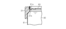
- the container 80 has a shape in which the diameter is temporarily reduced from the upper end due to the connection structure of the main body portion 81 and the upper lid portion 83, and then gradually enlarged and made constant. ing. That is, the side surface of the container 80 has a recess 81 a that is recessed from the upper end toward the inside of the container 80. The recess 81 a extends along the circumferential direction of the container 80 and is formed over the entire circumference of the container 80.
- the upper end fitting portion 21 of the foaming device 10 is provided with a convex portion 21 a that protrudes inward in the radial direction of the upper end fitting portion 21, and the convex portion 21 a has a shape that fits into the concave portion 81 a.
- the convex portion 21 a extends along the circumferential direction of the upper end fitting portion 21.
- the ultrasonic wave generation part 30 is provided with the above-mentioned ultrasonic wave generator 31 and the ultrasonic wave propagation member 32 which spreads in a sheet form.
- the ultrasonic wave propagation member 32 constitutes an inner side surface of the ultrasonic wave generator 30 and is in contact with the ultrasonic wave generator 31.
- the ultrasonic wave propagation member 32 is in contact with the side surface of the container 80 and is sandwiched between the ultrasonic wave generator 31 and the side surface of the container 80.
- the ultrasonic waves generated by the ultrasonic wave generator 31 are transmitted to the ultrasonic wave propagation member 32 and further transmitted from the ultrasonic wave propagation member 32 to the container 80.
- the ultrasonic wave propagation member 32 is in close contact with the ultrasonic wave generator 31 and the container 80, and is made of a material having flexibility capable of transmitting ultrasonic vibration.
- the ultrasonic wave propagation member 32 is made of, for example, silicone rubber.
- the ultrasonic wave propagation member 32 may be connected to the upper end fitting portion 21.
- the material which comprises the upper end fitting part 21 is not specifically limited.
- the upper end fitting portion 21 is made of a material that can impart elasticity to the upper end fitting portion 21 to such an extent that the upper end fitting portion 21 can be attached to and detached from the container 80.
- the upper end fitting portion 21 is made of resin such as silicone rubber or ABS resin.
- the upper end fitting portion 21 and the ultrasonic wave propagating member 32 may be formed as separate members and then connected, or the upper end fitting portion 21 and the ultrasonic wave propagating member 32 are made of the same material
- the upper end fitting portion 21 and the ultrasonic wave propagation member 32 may be integrally formed by, for example, pressing using a die. When the adhesion between the ultrasonic wave generator 31 and the container 80 is good, good transmission of the ultrasonic wave from the ultrasonic wave generator 31 to the container 80 is possible even if the ultrasonic wave propagation member 32 is not disposed. In some cases, the ultrasonic wave propagation member 32 may not be provided.
- the portion covering the outside of the ultrasonic wave generator 31 in the ultrasonic wave generator 30 is made of, for example, the same material as the upper end fitting portion 21 and embodied in a structure continuous from the upper end fitting portion 21 .
- the outer side surface of the ultrasonic wave generation unit 30 has a curved surface shape continuing from the upper end fitting unit 21, and the ultrasonic wave generation unit 30 has a size of the ultrasonic wave generation device 31. Depending on the height, it protrudes below the upper end fitting portion 21.
- the outer shape of the ultrasonic wave generator 30 and the material of the part covering the outer side of the ultrasonic wave generator 31 are not particularly limited.
- the accommodating part 40 which accommodates the drive part 41 and the electric power supply part 42 is the opposite side to the ultrasonic wave generation part 30 with respect to the centerline which is the center of the ring which the fitting part 20 comprises.
- the storage unit 40 is disposed on the opposite side of the container 80 to the ultrasonic wave generation unit 30.
- the outer shape of the housing portion 40 is not particularly limited, and the housing portion 40 may have a shape capable of housing the drive portion 41 and the power supply portion 42.
- the storage portion 40 has a shape extending downward from the fitting portion 20, and stores the dry battery exchangeably.
- a wire connecting the drive unit 41 and the power supply unit 42 to the ultrasonic wave generator 31 is passed through the inside of the upper end fitting unit 21.
- the operation unit 50 is also located on the opposite side of the center of the ring formed by the fitting unit 20 to the ultrasonic wave generation unit 30, that is, on the opposite side of the container 80 to the ultrasonic wave generation unit 30.
- the operation unit 50 is disposed in a region overlapping with the fitting portion 20 along the radial direction of the upper end fitting portion 21 in the outer side surface of the housing portion 40. That is, the operation unit 50 is disposed near the upper end of the container 80.
- the power supply part 42 accommodates a battery as an electric power source, the part in which the power supply part 42 is located among the foaming apparatuses 10 tends to be heavier than another part.
- a portion covering the ultrasonic wave generator 31 in the ultrasonic wave generator 30 is The balance of the weight in the foaming device 10 is determined at the portion where the power supply unit 42 is located, such as by forming thicker than the upper end fitting portion 21 or by including a member for adding weight to the ultrasonic wave generation unit 30 or the like. It may be adjusted not to be too biased. [How to use the foaming device] With reference to FIG. 9 and FIG. 10, while demonstrating the usage method of the foaming apparatus 10, the effect
- the user When using the foaming device 10, the user first attaches the foaming device 10 to the container 80. At this time, the user fits the fitting portion 20 into the container such that the ultrasonic wave generator 30 contacts the side surface of the container 80 below the spout 83 a of the container 80.
- the foaming device 10 may have a display for prompting the user to place the ultrasonic wave generation unit 30 below the spout 83a, and the instruction attached to the foaming device 10 may be used to An instruction to place the generator 30 below the spout 83a may be described.
- the spout 83a is opened before or after the attachment of the foaming device 10.
- the user lifts the frothing device 10 and the container 80 to place the frothing device 10 and the container 80 so that the spout 83a is on the lower side. It is inclined, and the effervescent beverage in the container 80 is drained from the spout 83 a and poured into a cup 90 such as a glass.
- the frothing device 10 is turned off.
- the user holds the container 80 together with the foaming device 10 from the side where the container 40 is positioned relative to the container 80. Thereby, the liquid foamy beverage Lq is poured into the cup 90 mainly.
- the user operates the operation unit 50 to switch on the foaming device 10 while continuing pouring the sparkling beverage.
- the frothing device 10 is turned off by operating the operation unit 50 while shifting the position of the index finger. You can easily switch from on to on.
- a drive signal is output from the drive unit 41 to the ultrasonic wave generator 31 based on the input of a signal from the operation unit 50, whereby the ultrasonic wave generator 31 emits ultrasonic waves.
- the ultrasonic waves are transmitted to the side surface of the container 80 through the ultrasonic wave propagation member 32 and further transmitted to the foamed beverage in the container 80.
- the effervescent beverage left in the container 80 at this point is part of the effervescent beverage that was initially filled in the container 80.
- the foamed beverage remaining in the container 80 is collected near the spout 83 a in the container 80 by the container 80 being inclined. If the ultrasonic wave generator 30 is in contact with the side surface of the container 80 below the spout 83a when the container 80 is kept stationary, the container 80 is inclined so that the foamed beverage is poured from the spout 83a.
- the ultrasonic wave generator 31 is located below the spout 83a, that is, in the vicinity of the portion of the container 80 where the effervescent beverage is collected. Therefore, the ultrasonic waves emitted from the ultrasonic wave generator 31 are properly transmitted to the foamed beverage in the container 80.
- the ultrasonic wave generated by the ultrasonic wave generator 31 is transmitted to the container 80 through the ultrasonic wave propagation member 32 in close contact with the ultrasonic wave generator 31 and the side surface of the container 80, the ultrasonic vibration in the propagation process Loss is reduced, and the transmission efficiency of ultrasound is enhanced.
- the ultrasonic vibration causes the foamed beverage in the container 80 to foam, and the foam Fm exits the spout 83 a and is poured into the cup 90. Thereby, the foamable beverage in the container 80 can be transferred to the cup 90 so that the foam Fm is placed on the liquid foamable beverage Lq in the cup 90.
- the ultrasonic waves emitted from the foaming device 10 are transmitted from the side surface of the container 80 to the foamed beverage in the container 80. Therefore, the sparkling beverage is poured without directly contacting the foaming device 10 and poured into the cup 90. Therefore, since it is not necessary to wash the foaming device 10 every time of use, the burden required to manage the foaming device 10 can be reduced. Even if the ultrasonic wave generator 30 is positioned below the spout 83a, the ultrasonic wave generator 30 contacts the upper end of the container 80 because the ultrasonic wave generator 30 is separated from the upper end of the container 80. Compared to the configuration described above, the foamed beverage flowing out of the spout 83a is less likely to adhere to the frothing device 10. Therefore, the burden required to manage the foaming device 10 can be further reduced.
- a device used to froth the upper part of the foamed beverage by bringing the side surface of the container into contact with the ultrasonic generator in a state where the container filled with the sparkling beverage is left standing. can be mentioned.
- the vibration is transmitted also to the liquid part in the lower part and carbonic acid is also released from this part, so that the flavor of the foamed beverage is likely to be deteriorated.
- the amount of the liquid portion also changes depending on the amount of foam generation, and this amount of foam depends on the position and time at which the ultrasonic wave generator contacts. change. Therefore, it is difficult to control the ratio of liquid to foam as desired by the user. Also, if the container is opaque, it is more difficult to control the ratio of liquid to foam as desired by the user, as the amount of foam generated can only be seen from the top of the container.
- the effervescent beverage poured into the cup 90 first is kept in the liquid state without receiving vibration, so that the decrease in flavor of the effervescent beverage can be suppressed. Since it is possible and also easy to grasp the quantity of the liquid part, it is easy to control the ratio of liquid to foam in the sparkling beverage.
- the ultrasonic wave generating unit 30 is disposed so as to be in contact with the side surface of the container 80 below the spout 83a.
- the ultrasonic waves generated by the ultrasonic wave generation unit 30 are transmitted from the side surface of the container 80 to the foamed beverage in the container 80, so the foamed beverage is foamed in the container 80 without directly touching the foaming device 10.
- Exit from spout 83a Therefore, since it is not necessary to wash the foaming device 10 every time of use, the burden required to manage the foaming device 10 can be reduced.
- the fitting portion 20 is fitted to the container 80 and surrounds the side surface of the container 80, It is hard to come off.
- the ultrasonic wave generating unit 30 constitutes a part of the fitting unit 20 and is disposed below the spout 83 a with respect to the upper end fitting unit 21 which is the other part of the fitting unit 20. Therefore, since the ultrasonic wave generation unit 30 is separated from the upper end of the container 80, the foamed beverage flowing out of the spout 83a is less likely to adhere to the frothing device 10. Thereby, the burden required for management of foaming device 10 can be reduced further.
- the fitting portion 20 has a shape that can be fitted to the container 80, which is a beverage can, when the user drinks the foamed beverage contained in a commercially available beverage can, the foaming device 10 is placed on the beverage can. Can be used directly attached. Therefore, as compared with, for example, the case where a dedicated container is required for using the frothing device 10, the versatility of the frothing device 10 is high, and the convenience for the user is also enhanced.
- the upper end fitting portion 21 has a shape capable of being fitted to the concave portion 81a of the container 80 which is a beverage can by having the convex portion 21a. Since the upper end fitting portion 21 is fitted to the container 80, the stability of the position of the foaming device 10 with respect to the container 80 can be enhanced. Further, since the vertical position of the fitting portion 20 in the upper portion of the container 80 is defined by the fitting of the convex portion 21 a and the concave portion 81 a, the fitting portion 20 including the ultrasonic wave generating portion 30 is It is easy to arrange in the appropriate position.
- the ultrasonic wave generation unit 30 includes the ultrasonic wave propagation member 32 in contact with the ultrasonic wave generation device 31, and the ultrasonic wave propagation member 32 is engaged with the ultrasonic wave generation device 31 by fitting the container 80 and the fitting portion 20. It contacts the side of the container 80 so as to be sandwiched between the side of the container 80 and the side. As a result, the ultrasonic waves generated by the ultrasonic wave generator 31 are transmitted to the container 80 through the ultrasonic wave propagation member 32 in close contact with the ultrasonic wave generator 31 and the side surface of the container 80, so the ultrasonic wave transmission efficiency is improved. Be enhanced.
- the drive unit 41, the power supply unit 42, and the operation unit 50 are directed to the center of the ring formed by the fitting unit 20. It is located on the opposite side of the ultrasonic wave generator 30.
- the user When the user pours the sparkling beverage from the container 80 into the cup 90, the user usually grips the container 80 from the opposite side of the spout 83a with respect to the central axis of the container 80. Therefore, according to the above configuration, the user can grasp the container 80 together with the housing unit 40 since the housing unit 40 for housing the driving unit 41 and the power supply unit 42 is located near the portion to which the palm of the user hits. . Therefore, the container 80 and the foaming device 10 can be easily grasped, and the stability of the position of the container 80 and the foaming device 10 when pouring the foamed beverage from the container 80 into the cup 90 is also enhanced.
- the operation unit 50 since the operation unit 50 is located in the vicinity of the portion held by the user, the user holds the container 80 and the foaming device 10 and pours the foamed beverage from the container 80 into the cup 90 while still holding the operation unit 50. It can be easily operated.
- Second Embodiment A second embodiment of a foamed beverage frothing device which is an example of an ultrasonic vibration application device will be described with reference to FIGS. 11 to 13.
- differences between the second embodiment and the first embodiment will be mainly described, and the same configuration as the first embodiment is denoted by the same reference numeral, and the description thereof will be omitted.
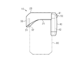
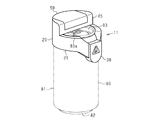
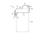
- FIG. 11 shows, the structure of the accommodating part differs in the foaming apparatus 11 of 2nd Embodiment compared with the foaming apparatus 10 of 1st Embodiment.
- foaming device 11 of a 2nd embodiment has the same composition as foaming device 10 of a 1st embodiment.
- the external shape of the ultrasonic wave generation unit 30 is arbitrary, and the shape exemplified in the first embodiment may be adopted regardless of the configuration of the accommodation unit, or the shape exemplified in the second embodiment may be adopted. And shapes different from these may be adopted.
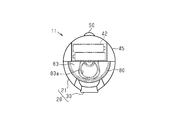
- the housing portion 45 is an upper end of a portion of the fitting portion 20 centered on a position opposite to the ultrasonic wave generating portion 30 with respect to the center of the ring formed by the fitting portion 20. It is connected with
- the housing portion 45 may be integrally formed with the fitting portion 20, or the housing portion 45 and the fitting portion 20 may be connected after being formed as separate members.
- the accommodating portion 45 When viewed from a direction along the axial direction of the fitting portion 20, the accommodating portion 45 covers approximately half of the upper lid portion 83 and pours from a region where the accommodating portion 45 is not located in the region surrounded by the fitting portion 20. The mouth 83a is exposed.
- the housing portion 45 houses the power supply portion 42 above the upper lid portion 83. That is, the power supply unit 42 is disposed above the container 80.
- the drive part 41 is located in the opposite side to the ultrasonic wave generation part 30 with respect to the center of the ring
- the drive unit 41 may be housed in the housing portion 45, may be housed inside the fitting portion 20, or may be housed straddling the housing portion 45 and the fitting portion 20.
- the housing portion for housing the driving portion 41 may be provided so as to protrude from the fitting portion 20 to the outer side in the radial direction of the upper end fitting portion 21.
- the operation unit 50 is located on the opposite side of the center of the ring formed by the fitting unit 20 with the ultrasonic wave generation unit 30.
- the operation unit 50 is a position overlapping with the drive unit 41 along the radial direction of the upper end fitting unit 21, that is, a region within the outer surface of the fitting unit 20 or the storage unit 45, or the outside of the fitting unit 20 It is provided in the area
- the frothing device 11 of the second embodiment is also used in the same manner as the frothing device 10 of the first embodiment. That is, the user turns the foaming device 10 off and pours an appropriate amount of the sparkling beverage from the container 80 into the cup 90, and then pours the foam generated by turning on the foaming device 10 from the container 80 into the cup 90.
- the portion where the power supply unit 42 is located in the bubbling device 11 tends to be heavier than the other portions.
- the structure of the structure including the container 80 and the frothing device 11 near the power supply unit 42 It becomes the center of gravity.
- the power supply unit 42 is disposed above the container 80, the power supply unit 42 is composed of the container 80 and the frothing device 11 as compared with the configuration disposed along the side of the container 80. It is easy to prevent the center of gravity of the structure from being biased with respect to the center of the structure. Therefore, when the container 80 and the frothing device 11 are placed upright on a horizontal surface, the container 80 and the frothing device 11 can be prevented from falling down. Therefore, handling when using the frothing device 11 is facilitated.
- the following effects can be obtained in addition to the effects (1) to (5) of the first embodiment.
- the power supply unit 42 is disposed above the container 80, the center of gravity of the structure including the container 80 and the foaming device 11 can be easily suppressed from being biased with respect to the center of the structure. Therefore, the container 80 and the frothing device 11 are less likely to fall down, and the handling when using the frothing device 11 is facilitated.
- the operation unit 50 is located in the vicinity of the portion held by the user, as in the first embodiment, the user holds the container 80 and the foaming device 10 and pours the foamed beverage from the container 80 into the cup 90
- the operation unit 50 can be easily operated.
- FIG. 14 shows, the accommodating part 46 which the foaming apparatus 12 of 3rd Embodiment has has extended below from the fitting part 20.
- the position of the lower end of the housing portion 46 in the vertical direction coincides with the position of the lower end of the container 80.
- the accommodation unit 46 accommodates the drive unit 41 and the power supply unit 42.
- the container 80 and the frothing device 12 are placed on a support such as a table, the lower end of the housing portion 46 comes in contact with the surface of the support together with the lower end of the container 80. That is, the container 80 and the frothing device 12 are supported by the support. Therefore, the container 80 and the frothing device 12 are less likely to fall down. In particular, even when the container 80 is close to the sky and the center of gravity of the structure including the container 80 and the foaming device 12 is biased with respect to the center of the structure, the container 80 and the foaming device 12 are prevented from falling down. Be Therefore, handling when using the frothing device 12 is facilitated.
- the power supply unit 42 tends to be heavy due to the storage of the battery as described above, if the storage unit 46 is configured to store the power supply unit 42 near its lower end, the positions of the container 80 and the foaming device 12 are Especially easy to stabilize.
- the length of the housing portion 46 in the vertical direction may be formed to a predetermined length according to the length of the container 80 to be attached, and the housing portion 46 corresponds to the length of the container 80 to be attached
- the vertical length may be changed.
- the length of the housing portion 46 is to be attached to two types of containers 80 having the same outer diameter and different lengths in the vertical direction, such as a beverage can having a capacity of 350 ml and a 500 ml beverage can. May be changeable in two steps.
- FIG. 15 shows an example of the frothing device 13 in which the length of the housing portion 46 is changeable.
- the housing portion 46 has a structure in which the inward portion 47 extending from the fitting portion 20 is inserted inside the exterior portion 48, and the exterior portion 48 is configured to be vertically slidable along the inward portion 47. ing.
- the inward portion 47 and the exterior portion 48 have a locking structure, and the exterior portion 48 is locked at each of two positions of the first position and the second position with respect to the inward portion 47.
- the first position is, for example, a position where the entire inward portion 47 is inserted into the exterior portion 48.
- the second position is a position in which a part of the inward portion 47 protrudes from the upper end of the exterior portion 48, and the exterior portion 48 is disposed lower than the first position.
- the entire length of the housing 46 is longer in the second position than in the first position.
- the locking structure is not particularly limited as long as the exterior portion 48 is locked to the inward portion 47.
- the locking structure is, for example, a structure in which a protrusion of the other is hooked in a groove of one of the inward portion 47 and the exterior portion 48 or a structure in which the projections of each of the inward portion 47 and the exterior portion 48 engage with each other. And so on.
- the length of the storage portion 46 is determined by attaching the frothing device 13 to the container 80 having a shorter length in the vertical direction among the two types of containers 80 to be attached In this case, the positions of the lower end of the housing portion 46 and the lower end of the container 80 are set to coincide with each other.
- the position of the exterior portion 48 is displaced from the first position to the second position, and the entire length of the accommodation portion 46 is extended.
- the length of the storage portion 46 is determined by attaching the frothing device 13 to the container 80 having the longer length in the vertical direction among the two types of containers 80 to be attached In this case, the positions of the lower end of the housing portion 46 and the lower end of the container 80 are set to coincide with each other.
- FIG. 15 shows the case in which after the frothing device 13 having the exterior portion 48 disposed at the first position is attached to the container 80 having the longer length in the vertical direction among the two types of containers 80 to be attached, An example is shown in which the portion 48 is moved to the second position. Thereby, the position of the up-and-down direction of the lower end of storage part 46 and the lower end of container 80 corresponds.
- the foaming device 13 may be attached to the container 80 after the exterior portion 48 is disposed at the second position in advance.
- the usage method of the foaming apparatus 12 and 13 of 3rd Embodiment is the same as that of the foaming apparatus 10 of 1st Embodiment.
- the operating unit 50 is located on the upper surface of the fitting unit 20 on the opposite side of the ultrasonic wave generating unit 30 with respect to the center of the ring formed by the fitting unit 20. Illustrated. Also in the first embodiment and the second embodiment, the operation unit 50 may be located on the upper surface of the fitting unit 20. With such a configuration, when the user operates the operation unit 50 with the index finger, the operation unit 50 can be easily operated.
- the structure for making the length of the accommodating part 46 changeable is not restricted to the said structure in which the exterior part 48 slides with respect to the inward part 47.
- the length of the accommodation portion 46 in the vertical direction may be changeable in three or more steps.
- the housing portion 46 is configured such that the position of the lower end of the housing portion 46 in the vertical direction coincides with the position of the lower end of the container 80.
- the above embodiments can be implemented with the following modifications.
- Partification A modification of the position of the operation unit 50 and the configuration around the operation unit 50 will be described.
- the first embodiment exemplifies a mode in which the user operates the operation unit 50 by grasping the container 80 together with the foaming device 10 so that the palm of the hand hits the housing unit 40.
- the user may grasp the foaming device and the container so that the back of the finger strikes the housing.
- the housing portion may be provided with a structure for guiding how the user holds the frothing device and the container.
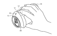
- the housing portion 49 may have a recess 51 around the operation portion 50.
- the operation unit 50 is located at the bottom of the recess 51.
- the user grips the frothing device 14 and the container 80 so as to operate the operation unit 50 by putting the index finger in the recess 51. That is, the manner in which the foaming device 14 and the container 80 are held is induced such that the back of the finger hits the housing 49.
- Such holding manner is easier for a user with a small hand to grasp the foaming device 14 and the container 80 as compared with the holding manner in which the palm strikes the housing.
- the forefinger since the forefinger does not have to be moved largely when operating the operation unit 50, it is easy to operate the operation unit 50 while grasping the foaming device 14 and the container 80.
- the user since the user can tilt the foaming device 14 and the container 80 while holding the lower side of the container 80 with the thumb while pouring the sparkling beverage, it is easy to stabilize the angle of the foaming device 14 and the container 80.
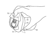
- the operation unit 50 may be disposed above the upper lid 83 of the container 80.
- the support portion 52 supporting the operation portion 50 is disposed above the upper lid portion 83, and the operation portion 50 is positioned on the upper surface of the support portion 52.
- the support portion 52 is connected to the upper end of a portion centering on a portion of the fitting portion 20 which is located on the side opposite to the ultrasonic wave generating portion 30 with respect to the center of the ring formed by the fitting portion 20 .
- the spout 83a is exposed from a region where the support portion 52 is not located in the region surrounded by the fitting portion 20 when viewed from the direction along the axial direction of the fitting portion 20.
- the user holds the foaming device 15 and the upper portion of the container 80 from the side opposite to the container 80 with respect to the ultrasonic wave generator 30.
- the operation unit 50 is disposed above the upper lid 83, the finger easily reaches the operation unit 50 when the forefinger is naturally stretched. Therefore, it is easy to operate the operation unit 50 while grasping the foaming device 15 and the container 80.
- the operation unit 50 may be disposed on the upper surface of the fitting unit 20 on the side of the spout 83a. In other words, the operation unit 50 is located on the upper surface of the portion connecting the ultrasonic wave generation unit 30 and the accommodation unit 40 in the fitting unit 20.
- the user holds the frothing device 16 and the container 80 from the opposite side of the container 80 to the ultrasonic wave generator 30.
- the operation unit 50 is disposed to the side of the spout 83 a, the finger can easily reach the operation unit 50 when the forefinger is extended. Therefore, it is easy to operate the operation unit 50 while grasping the foaming device 16 and the container 80.
- Whether the operation unit 50 is disposed on the right side or the left side with respect to the spout 83a may be determined according to which of right-handed and left-handed users is targeted. Alternatively, the operation unit 50 may be disposed at two places, the right side and the left side with respect to the spout 83a.
- FIG. 16 and FIG. 17 the foamer 14 illustrated the form provided with the display part 60.
- FIG. The display unit 60 indicates whether the foaming device is on or off, that is, whether or not the ultrasonic wave generator 31 is driven.
- the display unit 60 includes, for example, a light source such as an LED, and notifies the driving state of the ultrasonic wave generator 31 to the outside by lighting of the light source. According to such a configuration, the user can easily grasp the driving state of the ultrasonic wave generator 31.
- the frothing device of each of the above-described embodiments and modifications may also include the display unit 60.
- the position of the display unit 60 is not particularly limited, for example, as shown in FIGS. 16 and 17, when viewed from the direction along the axial direction of the ring formed by the fitting unit 20,
- the display unit 60 is disposed on the opposite side of the ultrasonic wave generation unit 30.
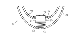
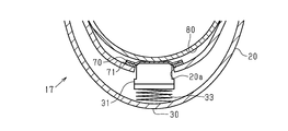
- the foaming device 17 shown in FIG. 22 includes a protective sheet 70 covering the ultrasonic wave generator 31 from the inside of the fitting portion 20.
- the protective sheet 70 covers the ultrasonic wave generator 31 and a portion surrounding the outer periphery of the ultrasonic wave generator 31 in the inner side surface 20S of the fitting portion 20.
- As the protective sheet 70 a sheet of a material that does not easily inhibit the transmission of ultrasonic waves and does not easily pass a liquid is used.
- a sheet made of a resin such as polyethylene terephthalate is used as the protective sheet 70.
- a portion of the inner side surface 20S of the fitting portion 20 to which the protective sheet 70 is attached constitutes the inner side surface of the ultrasonic wave generation unit 30.
- the bubbling device 17 does not include the ultrasonic wave propagation member 32, and the ultrasonic wave generator 31 receives the tip surface of the ultrasonic wave generator 31 from the opening 20 a of the inner side surface 20S of the fitting portion 20.
- the ultrasonic wave generation unit 30 includes an elastic member 33 which is, for example, a spring. The proximal end of the ultrasonic wave generator 31 is connected to the elastic member 33, and the amount of projection of the ultrasonic wave generator 31 from the opening 20a is changed by the expansion and contraction of the elastic member 33.
- a wire (not shown) connecting the ultrasonic wave generator 31 and the drive unit 41 is passed through the inside of the fitting unit 20.
- the protective sheet 70 is attached to the inner side surface 20S of the fitting portion 20 via the adhesive layer 71.
- the adhesive layer 71 is preferably disposed only between the inner side surface 20S of the fitting portion 20 and the protective sheet 70, and not disposed between the ultrasonic wave generator 31 and the protective sheet 70. That is, it is preferable that the ultrasonic wave generator 31 and the protective sheet 70 be in direct contact with each other. According to such a configuration, since the attenuation of the ultrasonic wave can be suppressed by passing through the adhesive layer 71, the transmission efficiency of the ultrasonic wave from the ultrasonic wave generator 31 to the container 80 can be enhanced.
- the protective sheet 70 has flexibility, and in accordance with a change in the amount of projection of the ultrasonic wave generator 31, follow the tip surface of the ultrasonic wave generator 31 and expand and contract.
- the amount of projection of the ultrasonic wave generator 31 is the largest, and the tip surface of the ultrasonic wave generator 31 is in contact with the protective sheet 70.
- the protective sheet 70, the ultrasonic wave generator 31, and the elastic member 33 are pushed from the side surface of the container 80.
- the ultrasonic wave generator 31 receives the restoring force of the elastic member 33 and is pressed to the side surface of the container 80 together with the protective sheet 70.
- the ultrasonic wave generator 31 protrudes excessively from the opening 20a, it is difficult to attach the fitting portion 20 to the container 80, particularly when the elasticity of the fitting portion 20 is small.
- the ultrasonic wave generator 31 does not protrude from the opening 20a, a gap is formed between the side surface of the container 80 and the ultrasonic wave generator 31 after the fitting part 20 is attached, and the ultrasonic wave is hard to transmit.
- the frothing device 17 when the fitting portion 20 is attached, the protrusion amount of the ultrasonic wave generating device 31 is finely adjusted by the deformation of the elastic member 33.
- the formation of a gap between the side surface of the container 80 and the ultrasonic wave generator 31 can be suppressed while suppressing an obstacle to the attachment of the ultrasonic wave. Therefore, the transmission efficiency of the ultrasonic wave from the ultrasonic wave generator 31 to the container 80 is enhanced.
- the protective sheet 70 covers the ultrasonic wave generator 31 and the periphery thereof from the inside of the fitting portion 20, so that the liquid is prevented from entering the vicinity of the ultrasonic wave generator 31.
- a slight gap be provided between the opening 20 a and the ultrasonic wave generator 31. Even in the case where such a gap is formed, the protective sheet 70 covers the ultrasonic wave generator 31 and the periphery from the inside of the fitting portion 20 so that liquid infiltrates in the vicinity of the ultrasonic wave generator 31. Can be properly suppressed.
- the foaming device 17 may not include the elastic member 33, and the position of the ultrasonic wave generator 31 may be fixed. Further, as in the above embodiments, the form in which the amount of projection of the ultrasonic wave generator 31 from the opening 20 a can be changed by the elastic member 33 may be applied to the form without the protective sheet 70. Another example of the structure for protecting the ultrasonic wave generator 31 from the infiltration of the liquid will be described.
- the opening 20 a is not provided on the inner side surface 20 S of the fitting unit 20, and the ultrasonic wave generator 31 is always accommodated inside the fitting unit 20.
- the ultrasonic wave generator 31 is housed inside the housing of the foaming device 18.
- the ultrasonic wave generation unit 30 is fitted with, for example, an elastic member 33 which is a spring, an internal protrusion 34 which protrudes from the side wall 20W of the fitting unit 20 to the inside of the fitting unit 20 and a side wall 20W of the fitting unit 20 And an external protrusion 35 protruding to the outside of the portion 20.
- the outer protrusion 35 protrudes from the inner surface 20S.
- a portion of the side wall 20W of the fitting portion 20 where the inner protrusion 34 and the outer protrusion 35 are located constitutes a side wall of the ultrasonic wave generator 30.
- the tip of the ultrasonic wave generator 31 is in contact with the internal projection 34, and the proximal end of the ultrasonic wave generator 31 is connected to the elastic member 33.
- the ultrasonic wave generator 31 is pressed against the internal projection 34 by the restoring force of the elastic member 33.
- the elastic member 33 in the present modification is provided to finely adjust the position of the ultrasonic wave generator 31 inside the fitting portion 20 and to make the ultrasonic wave generator 31 abut on the internal projection 34. If fine adjustment of the position of the ultrasonic wave generator 31 is unnecessary, the elastic member 33 may not be provided.
- the internal protrusions 34 have a cylindrical shape having a diameter smaller than that of the distal end surface of the ultrasonic wave generator 31.
- the distal end surface of the ultrasonic wave generator 31 emits a stronger ultrasonic wave closer to the center, so that the internal projection 34 contacts the central portion of the distal end surface of the ultrasonic wave generator 31 so that the transmission efficiency of the ultrasonic wave is generated. Can be enhanced.
- the outer protrusion 35 is provided at a position overlapping the inner protrusion 34 with the side wall 20W of the fitting portion 20 interposed therebetween.
- the outer protrusions 35 have a hemispherical shape having a bottom surface in the inner side surface of the fitting portion 20. Since the side surface of the container 80 is a curved surface, the tip of the external protrusion 35 is a curved surface and the external protrusion 35 and the side surface of the container 80 are in point contact with each other than the flat surface of the tip of the external protrusion 35 The transmission efficiency of ultrasonic waves can be improved.
- the external protrusion 35 is hemispherical, damage to the side surface of the container 80 by the tip of the external protrusion 35 when the external protrusion 35 contacts the side surface of the container 80 can be suppressed.
- the inner protrusion 34 and the outer protrusion 35 are made of, for example, the same material as the sidewall 20W of the fitting portion 20, and the sidewall 20W of the fitting portion 20, the inner protrusion 34, and the outer protrusion 35 are integrally formed. .
- the ultrasonic wave generator 31 since the ultrasonic wave generator 31 is accommodated in the inside of the fitting portion 20, it is possible to suppress the infiltration of the liquid in the vicinity of the ultrasonic wave generator 31. Then, since the ultrasonic wave is transmitted by the inner projection 34 and the outer projection 35, even if the ultrasonic wave generator 31 is not exposed to the outside of the fitting portion 20, the transmission efficiency of the ultrasonic wave is prevented from being lowered.
- a structure for suppressing the infiltration of the liquid may be provided around the drive unit 41 and the power supply unit 42.
- the foaming device 19 may be provided with the holding part 75 which functions as a handle.
- the grip portion 75 extends downward from the fitting portion 20 with a gap between the grip portion 75 and the side surface of the container 80. If the foaming device 19 is configured to include the gripping portion 75, the user can hold the foaming device 19 together with the container 80 by holding the gripping portion 75 through a finger between the side surface of the container 80 and the gripping portion 75. . Thus, even if the container 80 is large relative to the user's hand, the user can easily hold the frothing device 19 attached to the container 80.
- the storage portion may double as the grip portion 75, and the storage portion may be disposed at a position different from the grip portion 75.
- the frothing device may include a lower support that supports the lower portion of the container 80.
- the lower support may support, for example, the lower lid 82 of the container 80 from the lower side, or may be fitted to the lower portion of the side surface of the container 80 to support the lower portion of the container 80. If the foaming device is configured to include the lower support, the position of the foaming device relative to the container 80 is more stable, and the foaming device is less likely to be removed from the container 80.
- the fitting portion 20 may have a configuration to be fitted to the upper portion of the container 80, and may not fit with the recess 81a of the container 80, and the container at a position away from the upper end of the container 80 It may surround 80 sides.
- the fitting portion 20 may have an open ring in which a part of the ring is broken. In the vertical direction, the fitting portion 20 has a distance from the upper end of the container 80 within one half of the total length of the container 80 (in the case of a can whose diameter of the upper lid portion 83 is small) or less than one third (upper lid portion) In the case of a can having a diameter of 83, it may be fitted in the area of.
- the position of the upper end of the ultrasonic wave generation unit 30 may coincide with the position of the upper end of the upper end fitting portion 21. That is, the fitting portion 20 may be disposed along the upper end of the container 80 along the entire circumference thereof.
- the ultrasonic wave generation unit 30 may be connected to the fitting unit 20 as a part independent of the fitting unit 20 without configuring the fitting unit 20.
- the fitting portion 20 is constituted only by the upper end fitting portion 21, the upper end fitting portion 21 has a closed annular shape surrounding the entire circumference of the container 80, and the ultrasonic wave generating portion 30 is below the upper end fitting portion 21. It may be connected.
- the housing portion may constitute a part of the fitting portion 20. The point is that the position of the ultrasonic wave generation unit 30 may be defined by fitting the container 80 and the fitting unit 20, and the ultrasonic wave generation unit 30 has a distance from the upper end of the container 80 in the vertical direction It may be disposed in an area within a half of the total length of 80.
- the frothing device may be attached to the container 80 so as to cover a part of the upper surface of the container 80, and the spout 83a may be exposed to the outside when the frothing device is attached to the container 80 .
- a member that covers a part of the upper surface of the container 80 may be connected to the upper end of the annular fitting portion 20.
- each of the drive unit 41, the power supply unit 42, and the operation unit 50 may be different from those of the above-described embodiments and the respective modifications, and is accommodated according to the positions of the drive unit 41 and the power supply unit 42.
- a section may be provided.
- the ultrasonic wave generator 30 may be arranged to be in contact with the side surface of the container 80 below the spout 83 a by fitting the container 80 and the fitting unit 20.
- the other configuration of the frothing device, and the shape and arrangement of each part of the frothing device may be different from the above embodiments.
- the container to which the frothing device is attached is not limited to a beverage can, but may be a container having a spout.
- containers other than beverage cans include bottles, plastic bottles, and high-capacity beverage tanks for business use.
- the material of the container include metal, resin, glass and the like.
- the container may be a container capable of transmitting ultrasonic waves from the side to the beverage inside and the container having a thickness, and the fitting portion 20 can be fitted to the top of the container depending on the shape of the container It should just have a shape. Further, the strength of the ultrasonic wave emitted by the foaming device may be adjusted according to the material and thickness of the side wall of the container.
- the beverage to which ultrasonic vibration is applied is not limited to the sparkling beverage. Even in the case of a beverage which does not contain carbonic acid, as long as it is a beverage in which bubbles are generated by the application of ultrasonic vibration, it can be the target of the application of ultrasonic vibration by the ultrasonic vibration applying apparatus. Furthermore, even in the case of a beverage in which visible bubbles do not occur due to the application of ultrasonic vibration, the application of ultrasonic vibration contributes to various purposes such as improvement in taste and improvement in mouth feel, for example. Can be targeted for the application of ultrasonic vibrations by the ultrasonic vibration applying apparatus. The point is that if the beverage physical condition changes, such as visible bubbles, invisible tiny bubbles, and changes in surface tension, due to the application of ultrasonic vibrations, the ultrasonic vibration applying device It can be an object of ultrasonic vibration.
Landscapes
- Engineering & Computer Science (AREA)
- Mechanical Engineering (AREA)
- Health & Medical Sciences (AREA)
- Food Science & Technology (AREA)
- Organic Chemistry (AREA)
- Chemical & Material Sciences (AREA)
- Genetics & Genomics (AREA)
- Zoology (AREA)
- General Engineering & Computer Science (AREA)
- General Health & Medical Sciences (AREA)
- Biochemistry (AREA)
- Life Sciences & Earth Sciences (AREA)
- Wood Science & Technology (AREA)
- Bioinformatics & Cheminformatics (AREA)
- Toxicology (AREA)
- Devices For Dispensing Beverages (AREA)
- Distillation Of Fermentation Liquor, Processing Of Alcohols, Vinegar And Beer (AREA)
- Non-Alcoholic Beverages (AREA)
- Food-Manufacturing Devices (AREA)
- Packging For Living Organisms, Food Or Medicinal Products That Are Sensitive To Environmental Conditiond (AREA)
Abstract
Description
なお、上記課題は、発泡飲料を泡立てる装置に限らず、種々の目的で飲料に超音波振動を与える装置において共通する。
本発明は、管理に要する負担を軽減できる超音波振動付与装置を提供することを目的とする。
上記構成によれば、市販の飲料缶に入った飲料をユーザーが飲む際に、飲料缶に超音波振動付与装置を取り付けて用いることができる。したがって、例えば、超音波振動付与装置の利用のために専用の容器を要する場合と比較して、超音波振動付与装置の汎用性が高く、また、ユーザーの利便性も高められる。
上記構成によれば、超音波発生装置の発した超音波が、超音波伝播部材を介して容器に伝えられるため、超音波の伝達効率が高められる。
上記構成において、前記超音波発生部は、超音波発生装置を含み、前記超音波振動付与装置は、前記超音波発生装置を液体の浸入から保護するための構造を有してもよい。
図1~図10を参照して、超音波振動付与装置の一例である発泡飲料泡立て装置の第1実施形態を説明する。なお、以下の説明における上下方向は、発泡飲料泡立て装置が取り付けられる容器を水平面上に静置した場合における上下方向である。
図1を参照して、泡立て装置の全体構成を説明する。泡立て装置10は、発泡飲料の入った容器80に取り付けられて用いられる。泡立て装置10が容器80に取り付けられている状態においては、泡立て装置10は容器80の外側に位置する。
図2を参照して、泡立て装置10の電気的構成を説明する。泡立て装置10は、電気的構成として、上述の超音波発生部30に含まれる超音波発生装置31と、超音波発生装置31を駆動するための駆動信号を生成する駆動部41と、電力供給部42と、上述の操作部50とを備えている。駆動部41と電力供給部42とは、収容部40に収容されている。
図3~図8を参照して、泡立て装置10の詳細構成を説明する。
図3および図4が示すように、嵌合部20は閉環状を有し、容器80の上部に嵌められる。泡立て装置10が容器80に取り付けられているとき、嵌合部20は容器80の側面(外側面)を囲む。超音波発生部30は、嵌合部20の一部を構成しており、超音波を発する機能とともに、嵌合部20の一部として容器80に対して泡立て装置10を固定する機能を有する。
[泡立て装置の使用方法]
図9および図10を参照して、泡立て装置10の使用方法を説明しつつ、泡立て装置10の作用について説明する。
(1)容器80と嵌合部20との嵌合によって、超音波発生部30が、注ぎ口83aの下方にて容器80の側面に接するように配置される。これにより、超音波発生部30の発した超音波は、容器80の側面から容器80内の発泡飲料に伝わるため、発泡飲料は、泡立て装置10に直接触れることなく容器80内にて泡立てられて、注ぎ口83aから出る。したがって、使用の度に泡立て装置10を洗浄する必要がないため、泡立て装置10の管理に要する負担を軽減することができる。
図11~図13を参照して、超音波振動付与装置の一例である発泡飲料泡立て装置の第2実施形態を説明する。以下では、第2実施形態と第1実施形態との相違点を中心に説明し、第1実施形態と同様の構成については同じ符号を付してその説明を省略する。
収容部45は、上蓋部83の上方において、電力供給部42を収容する。すなわち、電力供給部42は、容器80の上方に配置される。
(7)電力供給部42が容器80の上方に配置されるため、容器80と泡立て装置11とからなる構造体の重心が構造体の中心に対して偏倚することを抑えやすい。したがって、容器80と泡立て装置11とが倒れにくくなり、泡立て装置11の使用に際しての取り扱いが容易となる。
図14および図15を参照して、超音波振動付与装置の一例である発泡飲料泡立て装置の第3実施形態を説明する。以下では、第3実施形態と第1実施形態との相違点を中心に説明し、第1実施形態と同様の構成については同じ符号を付してその説明を省略する。
(9)上下方向における収容部46の下端の位置と容器80の下端の位置とが一致するように、収容部46が構成されている。これにより、泡立て装置12,13が取り付けられた容器80が支持台に静置されているとき、容器80と泡立て装置12,13とが支持台に支持されるため、容器80と泡立て装置12,13とが倒れにくくなる。また、収容部46と容器80との下端の位置を合わせることで、容器80に対する泡立て装置12,13の位置合わせも容易に可能である。
上記各実施形態は、以下のように変更して実施することが可能である。
[操作部50の位置]
操作部50の位置および操作部50の周辺の構成の変形例を説明する。
第1実施形態では、掌が収容部40に当たるように、ユーザーが泡立て装置10とともに容器80を掴んで操作部50を操作する形態を例示した。これに限らず、ユーザーは、指の裏が収容部に当たるように泡立て装置および容器を掴んでもよい。さらに、収容部に、ユーザーによる泡立て装置および容器の持ち方を誘導するための構造が設けられていてもよい。
第1実施形態にて説明したように、超音波発生部30が容器80の上端から離れている構成であれば、注ぎ口83aから流れ出た発泡飲料が泡立て装置に付着し難い。しかしながら、仮に発泡飲料が超音波発生部30に付着した場合には、付着した発泡飲料あるいはその清掃に用いられる水分等である液体の浸入から、電子部品である超音波発生装置31が保護されていることが好ましい。こうした超音波発生装置31の保護のための構造について説明する。
超音波発生装置31を液体の浸入から保護するための構造の他の例について説明する。
なお、超音波発生装置31の周囲に加えて、駆動部41や電力供給部42の周囲にも、液体の浸入を抑えるための構造が設けられてもよい。
・図26が示す泡立て装置19のように、泡立て装置19は、持ち手として機能する把持部75を備えていてもよい。把持部75は、容器80の側面との間に隙間を有して、嵌合部20から下方に延びている。泡立て装置19が把持部75を備える構成であれば、ユーザーは、容器80の側面と把持部75との間に指を通して把持部75を握ることにより、泡立て装置19を容器80とともに持つことができる。したがって、ユーザーの手に対して容器80が大きい場合であっても、ユーザーは容器80に取り付けられた泡立て装置19を容易に持つことができる。なお、収容部が把持部75を兼ねていてもよいし、収容部は把持部75とは別の位置に配置されてもよい。
Claims (11)
- 飲料を収容する容器であって注ぎ口を上部に有する前記容器に取り付けられるように構成された超音波振動付与装置であって、
前記容器の上部に嵌められるように構成された環状の嵌合部と、
前記容器と前記嵌合部との嵌合によって、前記注ぎ口の下方にて前記容器の側面に接する位置に配置されるように構成された超音波発生部と、
を備える超音波振動付与装置。 - 前記容器は飲料缶であり、
前記嵌合部は、前記飲料缶に嵌合可能な形状を有している
請求項1に記載の超音波振動付与装置。 - 前記嵌合部は、前記飲料缶が有する凹部であって、前記飲料缶の上端から前記飲料缶の内側に向けて窪む前記凹部に嵌合可能な形状を有した上端嵌合部を備える
請求項2に記載の超音波振動付与装置。 - 前記超音波発生部は、超音波発生装置と、前記超音波発生装置と接する超音波伝播部材とを含み、前記容器と前記嵌合部との嵌合によって、前記超音波伝播部材が前記超音波発生装置と前記容器の側面との間に挟まれるように構成されている
請求項1~3のいずれか1項に記載の超音波振動付与装置。 - 前記超音波発生部は、前記嵌合部の一部を構成し、前記嵌合部の他の部分よりも前記注ぎ口に対して下方に配置されるように構成されている
請求項1~4のいずれか1項に記載の超音波振動付与装置。 - 前記超音波発生部が含む超音波発生装置の駆動信号を生成する駆動部と、
前記超音波発生装置の駆動を指示する操作を受け付ける操作部と、を備え、
前記駆動部および前記操作部は、前記嵌合部が構成する環の中心に対して前記超音波発生部とは反対側に位置する
請求項1~5のいずれか1項に記載の超音波振動付与装置。 - 前記超音波発生部が含む超音波発生装置の駆動信号を生成する駆動部と、
前記駆動部に電力を供給する電力供給部と、を備え、
前記電力供給部は、前記嵌合部が構成する環の中心に対して前記超音波発生部とは反対側に位置する
請求項1~6のいずれか1項に記載の超音波振動付与装置。 - 前記超音波発生部が含む超音波発生装置の駆動信号を生成する駆動部と、
前記駆動部に電力を供給する電力供給部と、を備え、
前記電力供給部は、前記容器の上方に配置されるように構成されている
請求項1~6のいずれか1項に記載の超音波振動付与装置。 - 前記超音波発生部が含む超音波発生装置の駆動信号を生成する駆動部と、
前記駆動部に電力を供給する電力供給部と、
前記電力供給部を収容する収容部と、を備え、
前記収容部は、前記嵌合部から下方に延び、上下方向における前記収容部の下端の位置と前記容器の下端の位置とが一致するように構成されている
請求項1~8のいずれか一項に記載の超音波振動付与装置。 - 前記超音波発生部が含む超音波発生装置の駆動信号を生成する駆動部と、
前記駆動部に電力を供給する電力供給部と、
前記電力供給部を収容する収容部と、を備え、
前記収容部は、前記嵌合部から下方に延び、上下方向における前記収容部の長さが変更可能に構成されている
請求項1~9のいずれか一項に記載の超音波振動付与装置。 - 前記超音波発生部は、超音波発生装置を含み、
前記超音波振動付与装置は、前記超音波発生装置を液体の浸入から保護するための構造を有する
請求項1~10のいずれか一項に記載の超音波振動付与装置。
Priority Applications (4)
| Application Number | Priority Date | Filing Date | Title |
|---|---|---|---|
| CN201880047637.2A CN110914192B (zh) | 2017-07-21 | 2018-07-19 | 超声波振动赋予装置 |
| JP2019513086A JP6536987B2 (ja) | 2017-07-21 | 2018-07-19 | 超音波振動付与装置 |
| KR1020207003995A KR102304505B1 (ko) | 2017-07-21 | 2018-07-19 | 초음파 진동 부여 장치 |
| US16/746,487 US11807840B2 (en) | 2017-07-21 | 2020-01-17 | Ultrasonic vibration imparting device |
Applications Claiming Priority (2)
| Application Number | Priority Date | Filing Date | Title |
|---|---|---|---|
| JP2017-141946 | 2017-07-21 | ||
| JP2017141946 | 2017-07-21 |
Related Child Applications (1)
| Application Number | Title | Priority Date | Filing Date |
|---|---|---|---|
| US16/746,487 Continuation-In-Part US11807840B2 (en) | 2017-07-21 | 2020-01-17 | Ultrasonic vibration imparting device |
Publications (1)
| Publication Number | Publication Date |
|---|---|
| WO2019017434A1 true WO2019017434A1 (ja) | 2019-01-24 |
Family
ID=65015138
Family Applications (1)
| Application Number | Title | Priority Date | Filing Date |
|---|---|---|---|
| PCT/JP2018/027103 Ceased WO2019017434A1 (ja) | 2017-07-21 | 2018-07-19 | 超音波振動付与装置 |
Country Status (4)
| Country | Link |
|---|---|
| JP (2) | JP6536987B2 (ja) |
| KR (1) | KR102304505B1 (ja) |
| CN (1) | CN110914192B (ja) |
| WO (1) | WO2019017434A1 (ja) |
Cited By (3)
| Publication number | Priority date | Publication date | Assignee | Title |
|---|---|---|---|---|
| JP2020111366A (ja) * | 2019-01-11 | 2020-07-27 | 株式会社タカラトミーアーツ | ビール泡立て装置 |
| JP2021031170A (ja) * | 2019-08-29 | 2021-03-01 | 凸版印刷株式会社 | 超音波振動付与装置 |
| US11807840B2 (en) | 2017-07-21 | 2023-11-07 | Toppan Printing Co., Ltd. | Ultrasonic vibration imparting device |
Families Citing this family (2)
| Publication number | Priority date | Publication date | Assignee | Title |
|---|---|---|---|---|
| JP7431017B2 (ja) * | 2019-11-25 | 2024-02-14 | サントリーホールディングス株式会社 | ビール泡立て装置 |
| GB2603963B (en) * | 2021-02-23 | 2023-02-22 | Diageo Ireland Unlimited Company | A pouring attachment device for a beverage container |
Citations (3)
| Publication number | Priority date | Publication date | Assignee | Title |
|---|---|---|---|---|
| JPH0242588Y2 (ja) * | 1984-09-13 | 1990-11-14 | ||
| JPH04253691A (ja) * | 1991-02-04 | 1992-09-09 | Daiichi Denki Kk | ビール超音波泡付け装置と方法 |
| JP3210007U (ja) * | 2016-02-25 | 2017-04-20 | 永▲チュン▼塑▲膠▼制品(深▲セン▼)有限公司 | 簡易ビール泡立て機 |
Family Cites Families (14)
| Publication number | Priority date | Publication date | Assignee | Title |
|---|---|---|---|---|
| WO2001036582A1 (en) * | 1999-11-17 | 2001-05-25 | Bass Public Limited Company | A beverage |
| JP4135568B2 (ja) * | 2003-06-11 | 2008-08-20 | 東洋製罐株式会社 | 超音波を利用した容器入りビールの泡立て装置及びその装置を利用した容器入りビールの泡立て方法 |
| JP2008302955A (ja) * | 2007-06-07 | 2008-12-18 | Igeta:Kk | ビール瓶等を利用した泡製造装置 |
| JP2012144258A (ja) | 2011-01-06 | 2012-08-02 | Tekkusu Iijii:Kk | 容器入り発泡飲料用泡立て装置 |
| JP6147014B2 (ja) * | 2013-02-05 | 2017-06-14 | 株式会社テックスイージー | 瓶入り発泡飲料用泡立て装置 |
| CN203302916U (zh) * | 2013-05-27 | 2013-11-27 | 郁鹤松 | 啤酒泡沫机 |
| JP6227433B2 (ja) * | 2013-07-12 | 2017-11-08 | サントリーホールディングス株式会社 | 注出装置 |
| CN203997562U (zh) * | 2014-01-04 | 2014-12-10 | 黄雄浩 | 一种啤酒起泡器 |
| CN204251326U (zh) * | 2014-11-27 | 2015-04-08 | 永骏塑胶制品(深圳)有限公司 | 便携式制泡啤酒机 |
| KR200478150Y1 (ko) * | 2015-03-25 | 2015-09-07 | (주)엠플러스기획 | 크림맥주 제조장치 |
| CN205527704U (zh) * | 2016-04-06 | 2016-08-31 | 永骏塑胶制品(深圳)有限公司 | 组合泡沫型啤酒机 |
| CN205872903U (zh) * | 2016-08-10 | 2017-01-11 | 广东顺德东方麦田工业设计有限公司 | 一种起泡器的瓶罐固定结构 |
| CN106185064B (zh) * | 2016-08-27 | 2018-07-20 | 刘军 | 一种防水起泡器 |
| CN106175492A (zh) * | 2016-09-19 | 2016-12-07 | 张民 | 便携式啤酒泡沫机及其制作泡沫的方法 |
-
2018
- 2018-07-19 WO PCT/JP2018/027103 patent/WO2019017434A1/ja not_active Ceased
- 2018-07-19 KR KR1020207003995A patent/KR102304505B1/ko active Active
- 2018-07-19 CN CN201880047637.2A patent/CN110914192B/zh active Active
- 2018-07-19 JP JP2019513086A patent/JP6536987B2/ja active Active
-
2019
- 2019-05-23 JP JP2019096895A patent/JP7098572B2/ja active Active
Patent Citations (3)
| Publication number | Priority date | Publication date | Assignee | Title |
|---|---|---|---|---|
| JPH0242588Y2 (ja) * | 1984-09-13 | 1990-11-14 | ||
| JPH04253691A (ja) * | 1991-02-04 | 1992-09-09 | Daiichi Denki Kk | ビール超音波泡付け装置と方法 |
| JP3210007U (ja) * | 2016-02-25 | 2017-04-20 | 永▲チュン▼塑▲膠▼制品(深▲セン▼)有限公司 | 簡易ビール泡立て機 |
Cited By (4)
| Publication number | Priority date | Publication date | Assignee | Title |
|---|---|---|---|---|
| US11807840B2 (en) | 2017-07-21 | 2023-11-07 | Toppan Printing Co., Ltd. | Ultrasonic vibration imparting device |
| JP2020111366A (ja) * | 2019-01-11 | 2020-07-27 | 株式会社タカラトミーアーツ | ビール泡立て装置 |
| JP2021031170A (ja) * | 2019-08-29 | 2021-03-01 | 凸版印刷株式会社 | 超音波振動付与装置 |
| JP7310448B2 (ja) | 2019-08-29 | 2023-07-19 | 凸版印刷株式会社 | 超音波振動付与装置 |
Also Published As
| Publication number | Publication date |
|---|---|
| JP6536987B2 (ja) | 2019-07-03 |
| JP2019156494A (ja) | 2019-09-19 |
| JPWO2019017434A1 (ja) | 2019-07-18 |
| CN110914192A (zh) | 2020-03-24 |
| CN110914192B (zh) | 2021-08-10 |
| KR102304505B1 (ko) | 2021-09-23 |
| KR20200024931A (ko) | 2020-03-09 |
| JP7098572B2 (ja) | 2022-07-11 |
Similar Documents
| Publication | Publication Date | Title |
|---|---|---|
| JP6536987B2 (ja) | 超音波振動付与装置 | |
| WO2012093517A1 (ja) | 容器入り発泡飲料用泡立て装置 | |
| JP6147014B2 (ja) | 瓶入り発泡飲料用泡立て装置 | |
| CN105492370B (zh) | 发泡饮料起泡装置和方法 | |
| EP4298031B1 (en) | A pouring attachment device for a beverage container | |
| HK40026617B (en) | Ultrasonic-wave vibration imparting device | |
| HK40026617A (en) | Ultrasonic-wave vibration imparting device | |
| US11807840B2 (en) | Ultrasonic vibration imparting device | |
| JP7310448B2 (ja) | 超音波振動付与装置 | |
| JP7298270B2 (ja) | 超音波振動付与装具 | |
| JP6200704B2 (ja) | 発泡飲料泡立て装置 | |
| JP7198404B2 (ja) | ビール泡立て装置 | |
| JP2013121846A (ja) | 発泡飲料泡立て装置 | |
| KR20140075523A (ko) | 띠 형상을 갖는 종이컵 홀더 | |
| JP2005000058A (ja) | 超音波を利用した容器入りビールの泡立て装置及びその装置を利用した容器入りビールの泡立て方法 | |
| JP3129147U (ja) | 飲食容器セットの構造 | |
| JP4903025B2 (ja) | 発泡飲料用の注ぎ口構造並びにそれを有する泡改善缶容器、泡改善ポリエチレンテレフタレート樹脂製容器、泡改善泡立て具、泡改善ディスペンサー及び泡改善発泡飲料用ピッチャー | |
| JP2021050039A (ja) | 飲料サーバー | |
| WO2018163429A1 (ja) | 泡立て装置 | |
| JP2020018199A (ja) | 過冷却状態解除装置 | |
| JPH0136759Y2 (ja) | ||
| JPH033473Y2 (ja) | ||
| JP2021083316A (ja) | ビール泡立て装置 | |
| JP2002284293A (ja) | 缶ビール用発泡装置 | |
| HK1219471B (en) | Effervescent beverage-foaming device and method |
Legal Events
| Date | Code | Title | Description |
|---|---|---|---|
| 121 | Ep: the epo has been informed by wipo that ep was designated in this application |
Ref document number: 18835031 Country of ref document: EP Kind code of ref document: A1 |
|
| ENP | Entry into the national phase |
Ref document number: 2019513086 Country of ref document: JP Kind code of ref document: A |
|
| NENP | Non-entry into the national phase |
Ref country code: DE |
|
| ENP | Entry into the national phase |
Ref document number: 20207003995 Country of ref document: KR Kind code of ref document: A |
|
| 122 | Ep: pct application non-entry in european phase |
Ref document number: 18835031 Country of ref document: EP Kind code of ref document: A1 |