WO2019017100A1 - 伝動ベルト及びその製造方法 - Google Patents
伝動ベルト及びその製造方法 Download PDFInfo
- Publication number
- WO2019017100A1 WO2019017100A1 PCT/JP2018/021693 JP2018021693W WO2019017100A1 WO 2019017100 A1 WO2019017100 A1 WO 2019017100A1 JP 2018021693 W JP2018021693 W JP 2018021693W WO 2019017100 A1 WO2019017100 A1 WO 2019017100A1
- Authority
- WO
- WIPO (PCT)
- Prior art keywords
- transmission belt
- polyolefin
- belt
- crosslinked
- coating layer
- Prior art date
- Legal status (The legal status is an assumption and is not a legal conclusion. Google has not performed a legal analysis and makes no representation as to the accuracy of the status listed.)
- Ceased
Links
Images










Classifications
-
- B—PERFORMING OPERATIONS; TRANSPORTING
- B29—WORKING OF PLASTICS; WORKING OF SUBSTANCES IN A PLASTIC STATE IN GENERAL
- B29D—PRODUCING PARTICULAR ARTICLES FROM PLASTICS OR FROM SUBSTANCES IN A PLASTIC STATE
- B29D29/00—Producing belts or bands
- B29D29/08—Toothed driving belts
-
- F—MECHANICAL ENGINEERING; LIGHTING; HEATING; WEAPONS; BLASTING
- F16—ENGINEERING ELEMENTS AND UNITS; GENERAL MEASURES FOR PRODUCING AND MAINTAINING EFFECTIVE FUNCTIONING OF MACHINES OR INSTALLATIONS; THERMAL INSULATION IN GENERAL
- F16G—BELTS, CABLES, OR ROPES, PREDOMINANTLY USED FOR DRIVING PURPOSES; CHAINS; FITTINGS PREDOMINANTLY USED THEREFOR
- F16G1/00—Driving-belts
- F16G1/28—Driving-belts with a contact surface of special shape, e.g. toothed
Definitions
- the present invention relates to a transmission belt and a method of manufacturing the same.
- Patent Document 1 discloses that, in a toothed belt, a tooth side surface in contact with a pulley is coated with an ultrahigh molecular weight polyethylene layer.
- Patent No. 4257120 gazette
- the present invention is a transmission belt provided with a surface coating layer on a pulley contact surface, and the surface coating layer is formed of a crosslinked polyolefin in which polyolefin molecules are crosslinked.
- the present invention is a method of producing a transmission belt according to the present invention, wherein the crosslinked polyolefin is obtained by irradiating uncrosslinked polyolefin in which polyolefin molecules are not crosslinked with radiation.
- FIG. 3 is a perspective view of a cross-linked polyolefin in which polyolefin molecules of one piece of the toothed belt according to the first embodiment are cross-linked;
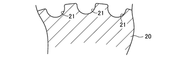
- FIG. 2 is a cross-sectional view of a portion of a cylindrical mold.
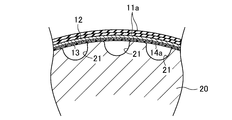
- FIG. 7 is a first explanatory view of a first manufacturing method of the toothed belt according to the first embodiment.
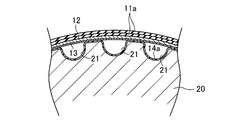
- FIG. 7 is a second explanatory view of the first manufacturing method of the toothed belt according to the first embodiment.
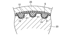
- 7 is a third explanatory view of the first manufacturing method of the toothed belt according to Embodiment 1.
- FIG. It is 4th explanatory drawing of the 1st manufacturing method of the toothed belt which concerns on Embodiment 1.
- FIG. 14 is a second explanatory view of the second and third manufacturing methods of the toothed belt according to the first embodiment.
- FIG. 14 is a third explanatory view of the second and third manufacturing methods of the toothed belt according to the first embodiment.
- FIG. 7 is a cross-sectional view of one tooth portion of a toothed belt according to a second embodiment.
- FIG. 14 is a first explanatory view of the method of manufacturing the toothed belt according to the second embodiment.
- FIG. 14 is a second explanatory view of the method of manufacturing the toothed belt according to the second embodiment.
- FIG. 10 is a cross-sectional view of one tooth portion of a toothed belt according to a third embodiment.
- FIG. 16 is a first explanatory view of the method of manufacturing the toothed belt according to the third embodiment.
- FIG. 14 is a second explanatory view of the method of manufacturing the toothed belt according to the third embodiment.
- FIG. 14 is a perspective view of a piece of a toothed belt according to a fourth embodiment. It is a perspective view of one piece of a toothed belt concerning other embodiments. It is a figure showing the pulley layout of a belt run test machine. It is a graph which shows tooth chipping life of an example and a comparative example.
- FIG. 1 shows a toothed belt B (transmission belt) according to a first embodiment.
- the toothed belt B according to the first embodiment is, for example, an endless belt used for automobiles, general industrial machines, and the like.
- the toothed belt B according to the first embodiment has, for example, a belt circumferential length of 100 mm to 2000 mm, a belt width of 3 mm to 100 mm, and a maximum belt thickness of 1.5 mm to 8.0 mm.
- the toothed belt B according to the first embodiment is provided with a plurality of teeth T at a constant pitch on the inner circumferential side.
- the pitch of the teeth T is, for example, 1.5 mm or more and 14 mm or less.
- the tooth portion T may be a round tooth having a semicircular shape in a side view, or may be a trapezoidal tooth having a trapezoidal shape, or may have another shape.
- the teeth T may be formed to extend in the belt width direction, or may be helical teeth formed to extend in a direction inclined with respect to the belt width direction.
- the toothed belt B includes a belt main body 11, a core 12, a reinforcing cloth 13, and a surface covering layer 14.
- the belt body 11 has a flat band portion 111 and a plurality of tooth main bodies 112 disposed on the inner peripheral side surface of the flat band portion 111 at a constant pitch.
- Each of the plurality of tooth portion main bodies 112 is integrally provided in the flat band portion 111.
- the belt body 11 is formed of an elastomer.
- the belt main body 11 is formed of a rubber composition in which an uncrosslinked rubber composition in which a compounding agent such as carbon black is blended with a rubber component such as hydrogenated nitrile rubber is heated and pressurized to crosslink the rubber component. Good.
- the belt body 11 may be formed of a cured polyurethane composition obtained by curing a urethane prepolymer composition in which a blending agent such as a curing agent and a plasticizer is blended with a urethane prepolymer and heated and pressed.
- the belt body 11 may be formed of a thermoplastic resin composition in which a compounding agent such as a plasticizer is blended with a thermoplastic resin such as polyurethane.
- the core wire 12 is embedded in the inner peripheral portion of the flat band portion 111 in the belt main body 11 so as to form a spiral having a pitch in the belt width direction.
- the outer diameter of the core wire 12 is, for example, 0.2 mm or more and 2 mm or less.
- the core wire 12 is made of, for example, a twisted yarn of glass fiber, aramid fiber, carbon fiber, metal fiber or the like.
- a twisted yarn which comprises the core wire 12 a single-twisted yarn, a multi-twisted yarn, a rung twisted yarn etc. are mentioned, for example.
- the core wire 12 may be configured such that S and Z strands are provided to form a double helix, and a single S or Z strand is provided to form a helix. It may be done.
- the core wire 12 is immersed in an epoxy resin solution or an isocyanate resin solution and then heated for adhesion to the belt main body 11, and then dipped in an aqueous solution of resorcin / formalin / latex (hereinafter referred to as “RFL aqueous solution”). It is preferable that at least one adhesion treatment of adhesion treatment to be heated and adhesion treatment to be dried after being immersed in a rubber paste be applied.
- the reinforcing cloth 13 is provided so as to cover the inner peripheral surface of the belt main body 11 on which the plurality of tooth portion main bodies 112 are disposed.
- the thickness of the reinforcing cloth 13 is, for example, 0.1 mm or more and 1 mm or less.
- the reinforcing cloth 13 is made of, for example, a cloth material such as nylon fiber such as nylon 6, 6 or polyester fiber or aramid fiber.
- the cloth material constituting the reinforcing cloth 13 include woven fabrics such as plain weave, twill weave, satin weave, etc .; knit fabrics such as plain knit, rubber knit, pearl knit, etc .; Bonding treatment to immerse in an epoxy resin solution or an isocyanate resin solution and then heat treatment for adhesion to the belt main body 11, adhesion treatment to heat after immersion in an RFL aqueous solution, and drying after being immersed in a rubber paste for adhesion to the belt body 11 It is preferable that at least one of adhesion treatment of adhesion treatment and adhesion treatment of coating the surface of the belt main body 11 with a rubber paste and then drying it is performed.
- the surface covering layer 14 is provided on the inner peripheral pulley contact surface so as to contact the surface of the reinforcing cloth 13 and cover the surface of the reinforcing cloth 13.
- the thickness of the surface coating layer 14 is, for example, 0.1 mm or more and 1.0 mm or less.
- the tooth portion T is configured by covering the tooth portion main body 112 of the belt main body 11 with the reinforcing cloth 13 and the surface covering layer 14.
- the surface coating layer 14 is composed of a sheet of crosslinked polyolefin (hereinafter, simply referred to as “crosslinked polyolefin”) in which polyolefin molecules are crosslinked.
- crosslinked polyolefin a sheet of crosslinked polyolefin in which polyolefin molecules are crosslinked.
- the surface coating layer 14 may be made of a cloth material formed of cross-linked polyolefin fibers.
- polystyrene resin examples include homopolymers such as polyethylene, polypropylene, poly-1-butene and poly-4-methyl-1-pentene; ethylene and propylene, 1-butene, 1-hexene, 1-octene And copolymers with ⁇ -olefins such as 4-methyl-1-pentene.
- the polyolefin is preferably one or more of these, and more preferably contains a homopolymer of polyethylene.
- the crosslinked polyolefin is preferably one obtained by crosslinking an ultrahigh molecular weight polyolefin having an average molecular weight (weight average molecular weight, number average molecular weight) of 500,000 or more from the viewpoint of obtaining excellent abrasion resistance.
- the average molecular weight (weight-average molecular weight, number-average molecular weight) of the ultrahigh molecular weight polyolefin is preferably 1,000,000 or more and 6,000,000 or less, more preferably 2,000,000 or more and 3,000,000 or less from the viewpoint of obtaining excellent abrasion resistance.
- the ultra high molecular weight polyolefin is preferably an ultra high molecular weight polyethylene.
- the limiting viscosity [ ⁇ ] of the crosslinked polyolefin is preferably 5 dl / g to 50 dl / g, more preferably 5 dl / g to 30 dl / g, from the viewpoint of obtaining excellent abrasion resistance.
- the limiting viscosity is that measured in decalin at 135 ° C.
- the melting point of the crosslinked polyolefin is preferably 125 ° C. or more and 145 ° C. or less, more preferably 130 ° C. or more and 145 ° C. or less, from the viewpoint of obtaining excellent abrasion resistance.
- the melting point is determined by differential scanning calorimetry (DSC).
- the crosslinked polyolefin which forms the surface coating layer 14 can be obtained by irradiating the uncrosslinked polyolefin in which the molecules of the polyolefin are not crosslinked.
- the uncrosslinked polyolefin is irradiated with radiation, cleavage and crosslinking of the molecular chains of the polyolefin occur, and as a result, the molecular chains are bonded at the crosslinking points.
- radiation include ⁇ rays, ⁇ rays, ⁇ rays, electron beams, ions and the like, and electron beams or ⁇ rays are preferably used.
- the irradiation dose of radiation is preferably 50 kGy or more and 700 kGy or less, more preferably 100 kGy or more and 500 kGy or less.
- FIG. 2 shows a cylindrical mold 20 used when manufacturing the toothed belt B according to the first embodiment.
- a plurality of tooth portion forming grooves 21 are disposed on the outer peripheral surface of the cylindrical mold 20 at intervals in the circumferential direction.
- the first method of manufacturing the toothed belt B according to the first embodiment is directed to the case where the belt main body 11 is formed of a rubber composition, and is used in the following member preparation process, molding process, crosslinking process, and finishing process. Configured
- ⁇ Member preparation process The uncrosslinked rubber composition obtained by masticating the rubber component, adding the compounding agent thereto, and kneading the resultant is calender-molded or the like to prepare an uncrosslinked rubber sheet 11a for forming the belt main body 11.
- a bonding process is performed on the yarn forming the core wire 12 and the cloth material forming the reinforcing cloth 13.
- the cross-linked polyolefin sheet 14 a for forming the surface coating layer 14 is obtained by irradiating the non-cross-linked polyolefin sheet in which the molecules of the polyolefin are not cross-linked with radiation.
- the cross-linked polyolefin sheet 14a and the reinforcing cloth 13 are formed into a cylindrical shape, and the cylindrical cross-linked polyolefin sheet 14a and the reinforcing cloth 13 are sequentially covered on the outer peripheral surface of the cylindrical mold 20 as shown in FIG.
- An uncrosslinked slab S ' is formed on the cylindrical mold 20 by spirally winding the core wire 12 thereon and then winding the uncrosslinked rubber sheet 11a thereon.
- the cross-linked polyolefin sheet 14 a and the reinforcing cloth 13 may be integrated by previously laminating them and heating.
- the cross-linked polyolefin sheet 14a may be provided along the tooth-forming groove 21 of the cylindrical mold 20, as shown in FIG. 3B.
- ⁇ Crosslinking step> As shown in FIG. 3C, a rubber sleeve 22 is placed on the non-crosslinked slab S 'on the cylindrical mold 20, and it is placed in the vulcanizer and sealed, and high temperature and high pressure steam is stored in the vulcanizer. Fill and hold for a predetermined molding time. At this time, the non-crosslinked slab S 'is pressed to the cylindrical mold 20 side and heated, so that the non-crosslinked rubber sheet 11a passes between the core wires 12 and presses the reinforcing cloth 13 and the crosslinked polyolefin sheet 14a. While flowing into each of the plurality of tooth portion forming grooves 21 of the cylindrical mold 20, the rubber component is crosslinked to form a cylindrical rubber composition.
- the cord 12 compositely integrates with the rubber composition.
- the reinforcing cloth 13 is also integrated with the rubber composition.
- the cross-linked polyolefin sheet 14 a melts and adheres to the surface of the reinforcing cloth 13 to form the surface coating layer 14.
- a cylindrical belt slab S is molded.
- ⁇ Finish process> Depressurize the inside of the vulcanizer to release the seal, take out the belt slab S molded between the cylindrical mold 20 and the rubber sleeve 22, remove it, and cut it into rings of a predetermined width according to the first embodiment.
- the toothed belt B is obtained.
- the second method of manufacturing the toothed belt B according to the first embodiment is directed to the case where the belt main body 11 is formed of a cured polyurethane composition, and includes the following member preparation step, molding step, casting step, and finish Composed of steps.
- a compounding agent is blended with the urethane prepolymer to prepare a liquid urethane prepolymer composition for forming the belt body 11. Further, the core wire 12 and the reinforcing cloth 13 are subjected to an adhesion process. Furthermore, the cross-linked polyolefin sheet 14 a for forming the surface coating layer 14 is obtained by irradiating the non-cross-linked polyolefin sheet in which the molecules of the polyolefin are not cross-linked with radiation.
- the cross-linked polyolefin sheet 14a and the reinforcing cloth 13 are cylindrically formed, and as shown in FIG. 4A, the cross-linked polyolefin sheet 14a is provided along the tooth portion forming groove 21 of the cylindrical mold 20, and then the tooth portion forming groove 21 is formed.
- the reinforcing cloth 13 is provided along the cross-linked polyolefin sheet 14a provided along the above, and then the core wire 12 is spirally wound thereon.
- the crosslinked polyolefin sheet 14a and the reinforcing cloth 13 may be integrated by previously laminating them and heating.
- ⁇ Casting process> As shown to FIG. 4B, the cylindrical metal mold 20 which provided the crosslinked polyolefin sheet 14a, the reinforcement cloth 13, and the core wire 12 is accommodated in the cylindrical outer mold 23. As shown in FIG. Thus, a cylindrical cavity-like cavity C is formed between the cylindrical mold 20 and the outer mold 23. Next, a liquid urethane prepolymer composition is cast and heated in the cavity C. At this time, the urethane prepolymer composition cures to form a tubular cured polyurethane composition. At the same time, the cord 12 composites with the cured polyurethane composition. In addition, the reinforcing cloth 13 is also combined and integrated with the cured polyurethane composition. Furthermore, the cross-linked polyolefin sheet 14 a melts and adheres to the surface of the reinforcing cloth 13 to form the surface coating layer 14. Finally, as shown in FIG. 4C, a cylindrical belt slab S is molded.
- the third method of manufacturing the toothed belt B according to the first embodiment is directed to the case where the belt main body 11 is formed of a thermoplastic resin composition, and includes the following member preparation step, molding step, casting step, and It consists of a finishing process.
- the following description will be made with reference to FIGS. 4A to 4C used in the description of the second manufacturing method.
- thermoplastic resin is heated and melted, and the compounding agent is blended therein to prepare a molten thermoplastic resin composition for forming the belt main body 11. Further, the core wire 12 and the reinforcing cloth 13 are subjected to an adhesion process. Furthermore, the cross-linked polyolefin sheet 14 a for forming the surface coating layer 14 is obtained by irradiating the non-cross-linked polyolefin sheet in which the molecules of the polyolefin are not cross-linked with radiation.
- the cross-linked polyolefin sheet 14a and the reinforcing cloth 13 are cylindrically formed, and as shown in FIG. 4A, the cross-linked polyolefin sheet 14a is provided along the tooth portion forming groove 21 of the cylindrical mold 20, and then the tooth portion forming groove 21 is formed.
- the reinforcing cloth 13 is provided along the cross-linked polyolefin sheet 14a provided along the above, and then the core wire 12 is spirally wound thereon.
- the crosslinked polyolefin sheet 14a and the reinforcing cloth 13 may be integrated by previously laminating them and heating.
- the cylindrical metal mold 20 which provided the crosslinked polyolefin sheet 14a, the reinforcement cloth 13, and the core wire 12 is accommodated in the cylindrical outer metal mold 23, and is accommodated.
- a cylindrical cavity-like cavity C is formed between the cylindrical mold 20 and the outer mold 23.
- the molten thermoplastic resin composition is cast into the cavity C and then cooled.
- the thermoplastic resin composition is solidified to form a tubular thermoplastic resin composition.
- the core wire 12 combines with the thermoplastic resin composition.
- the reinforcing cloth 13 is also combined and integrated with the thermoplastic resin composition.
- cross-linked polyolefin sheet 14a is heated and melted once and then cooled to be in close contact with the surface of the reinforcing cloth 13 to form the surface coating layer 14.
- a cylindrical belt slab S is molded.
- FIG. 5 shows a toothed belt B (transmission belt) according to a second embodiment.
- the part of the same name as Embodiment 1 is shown with the same code as Embodiment 1.
- the surface coating layer 14 is formed of a layer in which a large number of crosslinked polyolefin particles are fused or adhered.
- the particles of the crosslinked polyolefin can be obtained by irradiating the particles of the uncrosslinked polyolefin in which the molecules of the polyolefin are not crosslinked.
- the composition of the crosslinked polyolefin is the same as that of the first embodiment.
- the average particle diameter of the particles of the crosslinked polyolefin is preferably 10 ⁇ m or more and 200 ⁇ m or less, more preferably 100 ⁇ m or more and 150 ⁇ m or less, from the viewpoint of obtaining excellent abrasion resistance.
- the average particle size can be obtained by arithmetically averaging the particle sizes (maximum outer diameter) of 50 or more and 100 or less measured from the observation photograph by a scanning electron microscope in consideration of the magnification.
- the surface coating layer 14 may contain particles of uncrosslinked polyolefin other than particles of crosslinked polyolefin, particles of fluorine resin, and the like.
- the toothed belt B according to the second embodiment is reinforced as shown in FIG. 6A in place of the cross-linked polyolefin sheet 14a in the forming steps in the first to third manufacturing methods of the toothed belt B according to the first embodiment. It can manufacture by blowing the particle
- FIG. 7 shows a toothed belt B (transmission belt) according to a third embodiment.
- the part of the same name as Embodiment 1 is shown with the same code as Embodiment 1.
- the surface coating layer 14 is formed of a layer in which a large number of cross-linked polyolefin short fibers are fused or adhered.
- the short fibers of the crosslinked polyolefin are obtained by irradiating the fibers of the uncrosslinked polyolefin in which the molecules of the polyolefin before crosslinking into the short fibers are not crosslinked or the short fibers of the uncrosslinked polyolefin after cutting.
- the composition of the crosslinked polyolefin is the same as that of the first embodiment.
- the fineness of the filaments of the short fibers of the crosslinked polyolefin is preferably 0.3 dtex or more and 10 dtex or less, more preferably 0.5 dtex or more and 6 dtex or less, from the viewpoint of obtaining excellent abrasion resistance.
- the fiber length of the short fiber of the crosslinked polyolefin is preferably 0.5 mm or more and 5 mm or less, more preferably 1 mm or more and 3 mm or less, from the viewpoint of obtaining excellent abrasion resistance.
- the surface coating layer 14 may contain the short fiber of uncrosslinked polyolefin other than the short fiber of crosslinked polyolefin, other short fibers, and the like.
- the toothed belt B according to the third embodiment is reinforced as shown in FIG. 8A instead of the cross-linked polyolefin sheet 14 a in the forming steps in the first to third manufacturing methods of the toothed belt B according to the first embodiment. It can manufacture by blowing the short fiber of crosslinked polyolefin beforehand on the inner surface of the cloth 13, and providing the short fiber layer 14c. Moreover, it can manufacture also by providing the short fiber layer 14c by spraying the short fiber of crosslinked polyolefin beforehand on the outer peripheral surface of the cylindrical metal mold 20 instead of the crosslinked polyolefin sheet 14a, as shown to FIG. 8B.
- FIG. 9 shows a toothed belt B (transmission belt) according to a fourth embodiment.
- the part of the same name as Embodiment 1 is shown with the same code as Embodiment 1.
- the toothed belt B according to the fourth embodiment includes a belt body 11, a core 12 and a reinforcing cloth 13.
- the tooth portion T is configured by covering the tooth portion main body 112 of the belt main body 11 with the reinforcing cloth 13.
- the reinforcement cloth 13 is comprised with the cloth material formed with the fiber of crosslinked polyolefin, it comprises the surface coating layer.
- the fiber of the crosslinked polyolefin can be obtained by irradiating the fiber of the uncrosslinked polyolefin in which the molecules of the polyolefin before processing into the reinforcing cloth 13 are not crosslinked or the reinforcing cloth 13 after processing into radiation.
- the composition of the crosslinked polyolefin is the same as that of the first embodiment.
- Examples of the cloth material constituting the reinforcing cloth 13 include plain weave, twill weave, satin weave and the like woven of crosslinked polyolefin fiber yarn; plain knit, woven of crosslinked polyolefin fiber yarn, rubber knitting And knits such as pearl knits; non-woven fabrics formed of cross-linked polyolefin fibers; Bonding treatment to immerse in an epoxy resin solution or an isocyanate resin solution and then heat treatment for adhesion to the belt main body 11, adhesion treatment to heat after immersion in an RFL aqueous solution, and drying after being immersed in a rubber paste for adhesion to the belt body 11 It is preferable that at least one of adhesion treatment of adhesion treatment and adhesion treatment of coating the surface of the belt main body 11 with a rubber paste and then drying it is performed.
- the reinforcing cloth 13 may be formed to include fibers of uncrosslinked polyolefin other than fibers of crosslinked polyolefin, other fibers, and the like.
- the cross-linked polyolefin sheet 14a is not used, and the reinforcing cloth 13 is a fiber of cross-linked polyolefin. It can manufacture by using what was formed.
- the toothed belt B is shown in Embodiments 1 to 4 above, the present invention is not particularly limited to this, and in the case of a transmission belt provided with a surface coating layer formed of a crosslinked polyolefin on the pulley contact surface, It may be a friction transmission belt such as a flat belt, a V-belt, or a V-ribbed belt.
- the surface coating layer 14 is provided in contact with the surface of the reinforcing cloth 13 and covers the surface of the reinforcing cloth 13.
- the present invention is not particularly limited to this.
- the surface coating layer 14 may be configured to be in contact with the surface of the belt main body 11 and to directly cover the surface of the belt main body 11.
- the toothed belt B of the endless belt is shown, the present invention is not particularly limited thereto, and may be an open end belt.
- the toothed belt B in which the tooth portion T is disposed on the inner peripheral surface is shown, the present invention is not particularly limited to this, and both the inner peripheral surface and the outer peripheral surface are used. It may be a double-sided toothed belt provided with teeth.
- the uncrosslinked polyethylene sheet (thickness: 200 ⁇ m, weight average molecular weight: 2,000,000) in which the polyethylene molecules are not crosslinked is irradiated with 200 kGy of electron beam to obtain a crosslinked polyethylene sheet in which the polyethylene molecules are crosslinked.
- the toothed belt of the same composition as the above-mentioned Embodiment 1 which formed a surface coating layer using this crosslinked polyethylene sheet was produced, and made it an example.
- the belt circumferential length is 840 mm
- the belt width is 10 mm
- the tooth shape of the tooth portion is a round tooth (pitch: 8 mm) of S8M.
- the belt main body is formed of a rubber composition containing H-NBR reinforced by finely dispersing zinc methacrylate as a rubber component.
- the core wire was comprised of a twisted yarn of glass fiber subjected to RFL treatment and rubber paste treatment.
- the reinforcing cloth was made of a woven fabric of nylon fibers subjected to RFL treatment and rubber paste treatment.
- FIG. 11 shows a pulley layout of the belt travel tester 30.
- the belt traveling test apparatus 30 has a drive pulley 31 having 22 teeth corresponding to the tooth shape of S8M, and a driven pulley 32 having 22 teeth having the same configuration and provided on the right side.
- the driven pulley 32 is provided movably to the left and right so as to be able to load an axial load.
- the respective toothed belts B of the embodiment and the comparative example are wound around the driving pulley 31 and the driven pulley 32, and an axial constant load SW (set weight) of 1000 N is applied to the right on the driven pulley 32 to apply belt tension.
- SW set weight
- the drive pulley 31 was rotated at 5000 rpm to drive the belt.
- the belt travel is periodically stopped to check the loss of the teeth, that is, the presence or absence of the tooth missing, and the belt travel is ended when the tooth missing is detected, and the belt travel time until that time is the tooth missing life
- set weight set weight
- FIG. 12 shows the tooth chipping life of the example and the comparative example.
- the tooth chipping life is about 2 as compared with the comparative example in which the surface coating layer is formed of uncrosslinked polyethylene. You can see that it is twice as long. This is because the cross-linked polyethylene that forms the surface coating layer of the example is significantly enhanced in wear resistance by cross-linking of polyethylene molecules, and as a result, wear of the reinforcing cloth is suppressed and tooth chipping resistance It is thought that it is for improving the sex.
- the present invention is useful in the technical field of transmission belts and methods of making the same.
Landscapes
- Engineering & Computer Science (AREA)
- Mechanical Engineering (AREA)
- General Engineering & Computer Science (AREA)
Abstract
伝動ベルト(B)は、プーリ接触表面に表面被覆層(14)が設けられている。表面被覆層(14)は、ポリオレフィン分子同士が架橋された架橋ポリオレフィンで形成されている。
Description
本発明は、伝動ベルト及びその製造方法に関する。
伝動ベルトでは、耐久性の観点から、プーリとの接触による摩耗を抑制することが求められる。かかる伝動ベルトの耐摩耗性を向上させる手段として、例えば、特許文献1には、歯付ベルトにおいて、プーリに接触する歯部側表面を超高分子量ポリエチレン層で被覆することが開示されている。
本発明は、プーリ接触表面に表面被覆層が設けられた伝動ベルトであって、前記表面被覆層は、ポリオレフィン分子同士が架橋された架橋ポリオレフィンで形成されている。
本発明は、本発明の伝動ベルトの製造方法であって、前記架橋ポリオレフィンを、ポリオレフィン分子同士が架橋されていない未架橋ポリオレフィンに放射線を照射することにより得るものである。
以下、実施形態について詳細に説明する。
(実施形態1)
図1は、実施形態1に係る歯付ベルトB(伝動ベルト)を示す。実施形態1に係る歯付ベルトBは、例えば、自動車や一般産業用機械等に用いられるエンドレスベルトである。実施形態1に係る歯付ベルトBは、例えば、ベルト周長が100mm以上2000mm以下、ベルト幅が3mm以上100mm以下、ベルト最大厚さが1.5mm以上8.0mm以下である。
図1は、実施形態1に係る歯付ベルトB(伝動ベルト)を示す。実施形態1に係る歯付ベルトBは、例えば、自動車や一般産業用機械等に用いられるエンドレスベルトである。実施形態1に係る歯付ベルトBは、例えば、ベルト周長が100mm以上2000mm以下、ベルト幅が3mm以上100mm以下、ベルト最大厚さが1.5mm以上8.0mm以下である。
実施形態1に係る歯付ベルトBは、内周側に一定ピッチで複数の歯部Tが配設されている。歯部Tのピッチは、例えば1.5mm以上14mm以下である。歯部Tは、側面視形状が半円形である丸歯であってもよく、また、台形である台形歯であってもよく、さらには、その他の形状であってもよい。歯部Tは、ベルト幅方向に延びるように形成されていてもよく、また、ベルト幅方向に対して傾斜する方向に延びるように形成されたハス歯であってもよい。
実施形態1に係る歯付ベルトBは、ベルト本体11と、心線12と、補強布13と、表面被覆層14とを備えている。
ベルト本体11は、平帯部111と、その平帯部111の内周側の面に一定ピッチで配設された複数の歯部本体112とを有する。複数の歯部本体112のそれぞれは、平帯部111に一体に設けられている。
ベルト本体11は、エラストマーで形成されている。ベルト本体11は、水素化ニトリルゴム等のゴム成分にカーボンブラック等の配合剤が配合された未架橋ゴム組成物が加熱及び加圧されてゴム成分が架橋したゴム組成物で形成されていてもよい。また、ベルト本体11は、ウレタンプレポリマーに硬化剤や可塑剤等の配合剤が配合されたウレタンプレポリマー組成物が加熱及び加圧されて硬化した硬化ポリウレタン組成物で形成されていてもよい。さらに、ベルト本体11は、ポリウレタン等の熱可塑性樹脂に可塑剤等の配合剤が配合された熱可塑性樹脂組成物で形成されていてもよい。
心線12は、ベルト本体11における平帯部111の内周側部分に、ベルト幅方向にピッチを有する螺旋を形成するように配されて埋設されている。心線12の外径は、例えば0.2mm以上2mm以下である。
心線12は、例えば、ガラス繊維、アラミド繊維、カーボン繊維、金属繊維等の撚り糸で構成されている。心線12を構成する撚り糸としては、例えば、片撚り糸、諸撚り糸、ラング撚り糸等が挙げられる。心線12は、S撚り糸及びZ撚り糸が二重螺旋を形成するように設けられて構成されていてもよく、また、単一のS撚り糸又はZ撚り糸が螺旋を形成するように設けられて構成されていてもよい。心線12には、ベルト本体11との接着のため、エポキシ樹脂溶液やイソシアネート樹脂溶液に浸漬した後に加熱する接着処理、レゾルシン・ホルマリン・ラテックス水溶液(以下「RFL水溶液」という。)に浸漬した後に加熱する接着処理、及びゴム糊に浸漬した後に乾燥させる接着処理のうちの1種又は2種以上の接着処理が施されていることが好ましい。
補強布13は、ベルト本体11における複数の歯部本体112が配設された内周側の面を被覆するように設けられている。補強布13の厚さは、例えば0.1mm以上1mm以下である。
補強布13は、例えば、ナイロン6,6などのナイロン繊維、ポリエステル繊維、アラミド繊維等の布材で構成されている。補強布13を構成する布材としては、例えば、平織り、綾織り、朱子織などの織布;平編、ゴム編、パール編などの編物;不織布等が挙げられる。補強布13には、ベルト本体11との接着のため、エポキシ樹脂溶液やイソシアネート樹脂溶液に浸漬した後に加熱する接着処理、RFL水溶液に浸漬した後に加熱する接着処理、ゴム糊に浸漬した後に乾燥させる接着処理、及びベルト本体11側の面にゴム糊をコーティングした後に乾燥させる接着処理のうちの1種又は2種以上の接着処理が施されていることが好ましい。
表面被覆層14は、補強布13の表面に接触し且つ補強布13の表面を被覆するように内周側のプーリ接触表面に設けられている。表面被覆層14の厚さは、例えば0.1mm以上1.0mm以下である。実施形態1に係る歯付ベルトBでは、歯部Tは、ベルト本体11の歯部本体112が補強布13及び表面被覆層14で被覆されて構成されている。
表面被覆層14は、ポリオレフィン分子同士が架橋された架橋ポリオレフィン(以下、単に「架橋ポリオレフィン」という。)のシートで構成されている。実施形態1に係る歯付ベルトBによれば、このようにプーリ接触表面に設けられた表面被覆層14が、架橋ポリオレフィンで形成されていることにより、優れた耐摩耗性を得ることができる。そして、その結果、補強布13の摩耗が抑制され、優れた耐歯欠け性を得ることができる。なお、
表面被覆層14は、架橋ポリオレフィンの繊維で形成された布材で構成されていてもよい。
表面被覆層14は、架橋ポリオレフィンの繊維で形成された布材で構成されていてもよい。
架橋ポリオレフィンを構成するポリオレフィンとしては、例えば、ポリエチレン、ポリプロピレン、ポリ-1-ブテン、ポリ-4-メチル-1-ペンテンなどのホモポリマー;エチレンとプロピレン、1-ブテン、1-ヘキセン、1-オクテン、4-メチル-1-ペンテンなどのα-オレフィンとの共重合体等が挙げられる。ポリオレフィンは、これらのうち1種又は2種以上であることが好ましく、ポリエチレンのホモポリマーを含むことがより好ましい。
架橋ポリオレフィンは、優れた耐摩耗性を得る観点から、平均分子量(重量平均分子量、数平均分子量)が50万以上の超高分子量ポリオレフィンが架橋したものであることが好ましい。超高分子量ポリオレフィンの平均分子量(重量平均分子量、数平均分子量)は、優れた耐摩耗性を得る観点から、好ましくは100万以上600万以下、より好ましくは200万以上300万以下である。超高分子量ポリオレフィンは、超高分子量ポリエチレンであることが好ましい。
架橋ポリオレフィンの極限粘度[η]は、優れた耐摩耗性を得る観点から、好ましくは5dl/g以上50dl/g以下、より好ましくは5dl/g以上30dl/g以下である。この極限粘度は、135℃のデカリン中で測定されるものである。架橋ポリオレフィンの融点は、優れた耐摩耗性を得る観点から、好ましくは125℃以上145℃以下、より好ましくは130℃以上145℃以下である。この融点は、示差走査熱量測定(DSC)により求められる。
表面被覆層14を形成する架橋ポリオレフィンは、ポリオレフィンの分子同士が架橋されていない未架橋ポリオレフィンに放射線を照射することにより得ることができる。この場合、未架橋ポリオレフィンに放射線を照射すると、ポリオレフィンの分子鎖の切断と架橋とが生じ、その結果、分子鎖が架橋点で結合する。放射線としては、例えば、α線、β線、γ線、電子線、イオン等が挙げられるが、電子線又はγ線を用いることが好ましい。放射線の照射線量は、好ましくは50kGy以上700kGy以下、より好ましくは100kGy以上500kGy以下である。
次に、実施形態1に係る歯付ベルトBの製造方法について説明する。
図2は、実施形態1に係る歯付ベルトBを製造する際に用いる円筒金型20を示す。この円筒金型20の外周面には、複数の歯部形成溝21が周方向に間隔をおいて配設されている。
実施形態1に係る歯付ベルトBの第1の製造方法は、ベルト本体11がゴム組成物で形成されている場合を対象とし、次の部材準備工程、成形工程、架橋工程、及び仕上げ工程で構成される。
<部材準備工程>
ゴム成分を素練りし、そこに配合剤を投入して混練して得られた未架橋ゴム組成物をカレンダー成形等することによりベルト本体11形成用の未架橋ゴムシート11aを作製する。また、心線12を構成する撚り糸及び補強布13を構成する布材に接着処理を施す。さらに、ポリオレフィンの分子同士が架橋されていない未架橋ポリオレフィンシートに放射線を照射することにより、表面被覆層14形成用の架橋ポリオレフィンシート14aを得る。
ゴム成分を素練りし、そこに配合剤を投入して混練して得られた未架橋ゴム組成物をカレンダー成形等することによりベルト本体11形成用の未架橋ゴムシート11aを作製する。また、心線12を構成する撚り糸及び補強布13を構成する布材に接着処理を施す。さらに、ポリオレフィンの分子同士が架橋されていない未架橋ポリオレフィンシートに放射線を照射することにより、表面被覆層14形成用の架橋ポリオレフィンシート14aを得る。
<成形工程>
架橋ポリオレフィンシート14a及び補強布13を筒状に成形し、図3Aに示すように、円筒金型20の外周面上に、その筒状の架橋ポリオレフィンシート14a及び補強布13を順に被せ、次いで、その上から心線12を螺旋状に巻き付け、続いて、その上に未架橋ゴムシート11aを巻き付けることにより、円筒金型20上に未架橋スラブS’を成形する。なお、架橋ポリオレフィンシート14a及び補強布13は、予めそれらを積層して加熱することにより一体化させておいてもよい。また、架橋ポリオレフィンシート14aは、図3Bに示すように、円筒金型20の歯部形成溝21に沿うように設けてもよい。
架橋ポリオレフィンシート14a及び補強布13を筒状に成形し、図3Aに示すように、円筒金型20の外周面上に、その筒状の架橋ポリオレフィンシート14a及び補強布13を順に被せ、次いで、その上から心線12を螺旋状に巻き付け、続いて、その上に未架橋ゴムシート11aを巻き付けることにより、円筒金型20上に未架橋スラブS’を成形する。なお、架橋ポリオレフィンシート14a及び補強布13は、予めそれらを積層して加熱することにより一体化させておいてもよい。また、架橋ポリオレフィンシート14aは、図3Bに示すように、円筒金型20の歯部形成溝21に沿うように設けてもよい。
<架橋工程>
図3Cに示すように、円筒金型20上の未架橋スラブS’にゴムスリーブ22を被せ、それを加硫缶内に配置して密閉するとともに、加硫缶内に高温及び高圧の蒸気を充填して所定の成型時間だけ保持する。このとき、未架橋スラブS’が円筒金型20側に押圧されるとともに加熱されることにより、未架橋ゴムシート11aが心線12間を通過して補強布13及び架橋ポリオレフィンシート14aを押圧しながら円筒金型20の複数の歯部形成溝21のそれぞれに流入するとともにゴム成分が架橋して筒状のゴム組成物を形成する。それと同時に、心線12がゴム組成物と複合一体化する。また、補強布13もゴム組成物と複合一体化する。さらに、架橋ポリオレフィンシート14aが溶融して補強布13の表面に密着して表面被覆層14を構成する。そして、最終的に、図3Dに示すように、円筒状のベルトスラブSが成型される。
図3Cに示すように、円筒金型20上の未架橋スラブS’にゴムスリーブ22を被せ、それを加硫缶内に配置して密閉するとともに、加硫缶内に高温及び高圧の蒸気を充填して所定の成型時間だけ保持する。このとき、未架橋スラブS’が円筒金型20側に押圧されるとともに加熱されることにより、未架橋ゴムシート11aが心線12間を通過して補強布13及び架橋ポリオレフィンシート14aを押圧しながら円筒金型20の複数の歯部形成溝21のそれぞれに流入するとともにゴム成分が架橋して筒状のゴム組成物を形成する。それと同時に、心線12がゴム組成物と複合一体化する。また、補強布13もゴム組成物と複合一体化する。さらに、架橋ポリオレフィンシート14aが溶融して補強布13の表面に密着して表面被覆層14を構成する。そして、最終的に、図3Dに示すように、円筒状のベルトスラブSが成型される。
<仕上げ工程>
加硫缶の内部を減圧して密閉を解き、円筒金型20とゴムスリーブ22との間に成型されたベルトスラブSを取り出して脱型し、所定幅に輪切りすることにより実施形態1に係る歯付ベルトBを得る。
加硫缶の内部を減圧して密閉を解き、円筒金型20とゴムスリーブ22との間に成型されたベルトスラブSを取り出して脱型し、所定幅に輪切りすることにより実施形態1に係る歯付ベルトBを得る。
実施形態1に係る歯付ベルトBの第2の製造方法は、ベルト本体11が硬化ポリウレタン組成物で形成されている場合を対象とし、次の部材準備工程、成形工程、注型工程、及び仕上げ工程で構成される。
<部材準備工程>
ウレタンプレポリマーに配合剤を配合してベルト本体11形成用の液状のウレタンプレポリマー組成物を調製する。また、心線12及び補強布13に接着処理を施す。さらに、ポリオレフィンの分子同士が架橋されていない未架橋ポリオレフィンシートに放射線を照射することにより、表面被覆層14形成用の架橋ポリオレフィンシート14aを得る。
ウレタンプレポリマーに配合剤を配合してベルト本体11形成用の液状のウレタンプレポリマー組成物を調製する。また、心線12及び補強布13に接着処理を施す。さらに、ポリオレフィンの分子同士が架橋されていない未架橋ポリオレフィンシートに放射線を照射することにより、表面被覆層14形成用の架橋ポリオレフィンシート14aを得る。
<成形工程>
架橋ポリオレフィンシート14a及び補強布13を筒状に成形し、図4Aに示すように、架橋ポリオレフィンシート14aを円筒金型20の歯部形成溝21に沿うように設け、次いで、歯部形成溝21に沿って設けられた架橋ポリオレフィンシート14aに沿うように補強布13を設け、続いて、その上から心線12を螺旋状に巻き付ける。架橋ポリオレフィンシート14a及び補強布13は、予めそれらを積層して加熱することにより一体化させておいてもよい。
架橋ポリオレフィンシート14a及び補強布13を筒状に成形し、図4Aに示すように、架橋ポリオレフィンシート14aを円筒金型20の歯部形成溝21に沿うように設け、次いで、歯部形成溝21に沿って設けられた架橋ポリオレフィンシート14aに沿うように補強布13を設け、続いて、その上から心線12を螺旋状に巻き付ける。架橋ポリオレフィンシート14a及び補強布13は、予めそれらを積層して加熱することにより一体化させておいてもよい。
<注型工程>
図4Bに示すように、架橋ポリオレフィンシート14a、補強布13、及び心線12を設けた円筒金型20を、円筒状の外金型23の中に収容する。これにより、円筒金型20と外金型23との間には円筒孔状のキャビティCが構成される。次いで、そのキャビティCに、液状のウレタンプレポリマー組成物を注型して加熱する。このとき、ウレタンプレポリマー組成物が硬化して筒状の硬化ポリウレタン組成物を形成する。それと同時に、心線12が硬化ポリウレタン組成物と複合一体化する。また、補強布13も硬化ポリウレタン組成物と複合一体化する。さらに、架橋ポリオレフィンシート14aが溶融して補強布13の表面に密着して表面被覆層14を構成する。そして、最終的に、図4Cに示すように、円筒状のベルトスラブSが成型される。
図4Bに示すように、架橋ポリオレフィンシート14a、補強布13、及び心線12を設けた円筒金型20を、円筒状の外金型23の中に収容する。これにより、円筒金型20と外金型23との間には円筒孔状のキャビティCが構成される。次いで、そのキャビティCに、液状のウレタンプレポリマー組成物を注型して加熱する。このとき、ウレタンプレポリマー組成物が硬化して筒状の硬化ポリウレタン組成物を形成する。それと同時に、心線12が硬化ポリウレタン組成物と複合一体化する。また、補強布13も硬化ポリウレタン組成物と複合一体化する。さらに、架橋ポリオレフィンシート14aが溶融して補強布13の表面に密着して表面被覆層14を構成する。そして、最終的に、図4Cに示すように、円筒状のベルトスラブSが成型される。
<仕上げ工程>
外金型23から円筒金型20をベルトスラブSとともに取り出した後、円筒金型20からベルトスラブSを脱型し、所定幅に輪切りすることにより実施形態1に係る歯付ベルトBを得る。
外金型23から円筒金型20をベルトスラブSとともに取り出した後、円筒金型20からベルトスラブSを脱型し、所定幅に輪切りすることにより実施形態1に係る歯付ベルトBを得る。
実施形態1に係る歯付ベルトBの第3の製造方法は、ベルト本体11が熱可塑性樹脂組成物で形成されている場合を対象とし、次の部材準備工程、成形工程、注型工程、及び仕上げ工程で構成される。なお、以下では、第2の製造方法の説明で用いた図4A~Cを用いて説明する。
<部材準備工程>
熱可塑性樹脂を加熱して溶融させ、そこに配合剤を配合してベルト本体11形成用の溶融した熱可塑性樹脂組成物を調製する。また、心線12及び補強布13に接着処理を施す。さらに、ポリオレフィンの分子同士が架橋されていない未架橋ポリオレフィンシートに放射線を照射することにより、表面被覆層14形成用の架橋ポリオレフィンシート14aを得る。
熱可塑性樹脂を加熱して溶融させ、そこに配合剤を配合してベルト本体11形成用の溶融した熱可塑性樹脂組成物を調製する。また、心線12及び補強布13に接着処理を施す。さらに、ポリオレフィンの分子同士が架橋されていない未架橋ポリオレフィンシートに放射線を照射することにより、表面被覆層14形成用の架橋ポリオレフィンシート14aを得る。
<成形工程>
架橋ポリオレフィンシート14a及び補強布13を筒状に成形し、図4Aに示すように、架橋ポリオレフィンシート14aを円筒金型20の歯部形成溝21に沿うように設け、次いで、歯部形成溝21に沿って設けられた架橋ポリオレフィンシート14aに沿うように補強布13を設け、続いて、その上から心線12を螺旋状に巻き付ける。架橋ポリオレフィンシート14a及び補強布13は、予めそれらを積層して加熱することにより一体化させておいてもよい。
架橋ポリオレフィンシート14a及び補強布13を筒状に成形し、図4Aに示すように、架橋ポリオレフィンシート14aを円筒金型20の歯部形成溝21に沿うように設け、次いで、歯部形成溝21に沿って設けられた架橋ポリオレフィンシート14aに沿うように補強布13を設け、続いて、その上から心線12を螺旋状に巻き付ける。架橋ポリオレフィンシート14a及び補強布13は、予めそれらを積層して加熱することにより一体化させておいてもよい。
<注型工程>
図4Bに示すように、架橋ポリオレフィンシート14a、補強布13、及び心線12を設けた円筒金型20を、円筒状の外金型23の中に収容収容する。これにより、円筒金型20と外金型23との間には円筒孔状のキャビティCが構成される。次いで、そのキャビティCに、溶融した熱可塑性樹脂組成物を注型した後に冷却する。このとき、熱可塑性樹脂組成物が固化して筒状の熱可塑性樹脂組成物を形成する。それと同時に、心線12が熱可塑性樹脂組成物と複合一体化する。また、補強布13も熱可塑性樹脂組成物と複合一体化する。さらに、架橋ポリオレフィンシート14aが一旦昇温して溶融した後に冷却されることにより補強布13の表面に密着して表面被覆層14を構成する。そして、最終的に、図4Cに示すように、円筒状のベルトスラブSが成型される。
図4Bに示すように、架橋ポリオレフィンシート14a、補強布13、及び心線12を設けた円筒金型20を、円筒状の外金型23の中に収容収容する。これにより、円筒金型20と外金型23との間には円筒孔状のキャビティCが構成される。次いで、そのキャビティCに、溶融した熱可塑性樹脂組成物を注型した後に冷却する。このとき、熱可塑性樹脂組成物が固化して筒状の熱可塑性樹脂組成物を形成する。それと同時に、心線12が熱可塑性樹脂組成物と複合一体化する。また、補強布13も熱可塑性樹脂組成物と複合一体化する。さらに、架橋ポリオレフィンシート14aが一旦昇温して溶融した後に冷却されることにより補強布13の表面に密着して表面被覆層14を構成する。そして、最終的に、図4Cに示すように、円筒状のベルトスラブSが成型される。
<仕上げ工程>
外金型23から円筒金型20をベルトスラブSとともに取り出した後、円筒金型20からベルトスラブSを脱型し、所定幅に輪切りすることにより実施形態1に係る歯付ベルトBを得る。
外金型23から円筒金型20をベルトスラブSとともに取り出した後、円筒金型20からベルトスラブSを脱型し、所定幅に輪切りすることにより実施形態1に係る歯付ベルトBを得る。
(実施形態2)
図5は、実施形態2に係る歯付ベルトB(伝動ベルト)を示す。なお、実施形態1と同一名称の部分は、実施形態1と同一符号で示す。
図5は、実施形態2に係る歯付ベルトB(伝動ベルト)を示す。なお、実施形態1と同一名称の部分は、実施形態1と同一符号で示す。
実施形態2に係る歯付ベルトBでは、表面被覆層14は、多数の架橋ポリオレフィンの粒子が融着乃至密着した層で構成されている。架橋ポリオレフィンの粒子は、ポリオレフィンの分子同士が架橋されていない未架橋ポリオレフィンの粒子に放射線を照射することにより得ることができる。架橋ポリオレフィンの構成は実施形態1と同一である。
架橋ポリオレフィンの粒子の平均粒子径は、優れた耐摩耗性を得る観点から、好ましくは10μm以上200μm以下、より好ましくは100μm以上150μm以下である。この平均粒子径は、走査型電子顕微鏡による観察写真から拡大倍率を考慮して実測した50個以上100個以下の粒子径(最大外径)を算術平均することにより求められる。
なお、表面被覆層14は、架橋ポリオレフィンの粒子以外の未架橋ポリオレフィンの粒子やフッ素樹脂の粒子等を含んでいてもよい。
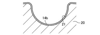
実施形態2に係る歯付ベルトBは、実施形態1に係る歯付ベルトBの第1~第3の製造方法における成形工程において、架橋ポリオレフィンシート14aの代わりに、図6Aに示すように、補強布13の内側面に予め架橋ポリオレフィンの粒子を吹き付けて粒子層14bを設けることにより製造することができる。また、架橋ポリオレフィンシート14aの代わりに、図6Bに示すように、円筒金型20の外周面に予め架橋ポリオレフィンの粒子を吹き付けて粒子層14bを設けることによっても製造することができる。
その他の構成及び作用効果は実施形態1と同一である。
(実施形態3)
図7は、実施形態3に係る歯付ベルトB(伝動ベルト)を示す。なお、実施形態1と同一名称の部分は、実施形態1と同一符号で示す。
図7は、実施形態3に係る歯付ベルトB(伝動ベルト)を示す。なお、実施形態1と同一名称の部分は、実施形態1と同一符号で示す。
実施形態3に係る歯付ベルトBでは、表面被覆層14は、多数の架橋ポリオレフィンの短繊維が融着乃至密着した層で構成されている。架橋ポリオレフィンの短繊維は、短繊維に切断する前のポリオレフィンの分子同士が架橋されていない未架橋ポリオレフィンの繊維、又は、切断した後の未架橋ポリオレフィンの短繊維に放射線を照射することにより得ることができる。架橋ポリオレフィンの構成は実施形態1と同一である。
架橋ポリオレフィンの短繊維のフィラメントの繊度は、優れた耐摩耗性を得る観点から、好ましくは0.3dtex以上10dtex以下、より好ましくは0.5dtex以上6dtex以下である。架橋ポリオレフィンの短繊維の繊維長は、優れた耐摩耗性を得る観点から、好ましくは0.5mm以上5mm以下、より好ましくは1mm以上3mm以下である。
なお、表面被覆層14は、架橋ポリオレフィンの短繊維以外の未架橋ポリオレフィンの短繊維やその他の短繊維等を含んでいてもよい。
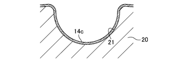
実施形態3に係る歯付ベルトBは、実施形態1に係る歯付ベルトBの第1~第3の製造方法における成形工程において、架橋ポリオレフィンシート14aの代わりに、図8Aに示すように、補強布13の内側面に予め架橋ポリオレフィンの短繊維を吹き付けて短繊維層14cを設けることにより製造することができる。また、架橋ポリオレフィンシート14aの代わりに、図8Bに示すように、円筒金型20の外周面に予め架橋ポリオレフィンの短繊維を吹き付けて短繊維層14cを設けることによっても製造することができる。
その他の構成及び作用効果は実施形態1と同一である。
(実施形態4)
図9は、実施形態4に係る歯付ベルトB(伝動ベルト)を示す。なお、実施形態1と同一名称の部分は、実施形態1と同一符号で示す。
図9は、実施形態4に係る歯付ベルトB(伝動ベルト)を示す。なお、実施形態1と同一名称の部分は、実施形態1と同一符号で示す。
実施形態4に係る歯付ベルトBは、ベルト本体11と、心線12と、補強布13とを備えている。実施形態4に係る歯付ベルトBでは、歯部Tは、ベルト本体11の歯部本体112が補強布13で被覆されて構成されている。そして、補強布13は、架橋ポリオレフィンの繊維で形成された布材で構成されているとともに、表面被覆層を構成している。架橋ポリオレフィンの繊維は、補強布13に加工する前のポリオレフィンの分子同士が架橋されていない未架橋ポリオレフィンの繊維、又は、加工後の補強布13に放射線を照射することにより得ることができる。架橋ポリオレフィンの構成は実施形態1と同一である。
補強布13を構成する布材としては、例えば、架橋ポリオレフィンの繊維の糸で織られた平織り、綾織り、朱子織などの織布;架橋ポリオレフィンの繊維の糸で編まれた平編、ゴム編、パール編などの編物;架橋ポリオレフィンの繊維で形成された不織布等が挙げられる。補強布13には、ベルト本体11との接着のため、エポキシ樹脂溶液やイソシアネート樹脂溶液に浸漬した後に加熱する接着処理、RFL水溶液に浸漬した後に加熱する接着処理、ゴム糊に浸漬した後に乾燥させる接着処理、及びベルト本体11側の面にゴム糊をコーティングした後に乾燥させる接着処理のうちの1種又は2種以上の接着処理が施されていることが好ましい。
なお、補強布13は、架橋ポリオレフィンの繊維以外の未架橋ポリオレフィンの繊維やその他の繊維等を含んで形成されていてもよい。
実施形態4に係る歯付ベルトBは、実施形態1に係る歯付ベルトBの第1~第3の製造方法において、架橋ポリオレフィンシート14aを用いず、且つ補強布13として、架橋ポリオレフィンの繊維で形成されたものを用いることにより製造することができる。
その他の構成及び作用効果は実施形態1と同一である。
(その他の実施形態)
上記実施形態1~4では、歯付ベルトBを示したが、特にこれに限定されるものではなく、プーリ接触表面に架橋ポリオレフィンで形成された表面被覆層が設けられた伝動ベルトであれば、平ベルト、Vベルト、Vリブドベルト等の摩擦伝動ベルトであってもよい。
上記実施形態1~4では、歯付ベルトBを示したが、特にこれに限定されるものではなく、プーリ接触表面に架橋ポリオレフィンで形成された表面被覆層が設けられた伝動ベルトであれば、平ベルト、Vベルト、Vリブドベルト等の摩擦伝動ベルトであってもよい。
上記実施形態1~3では、表面被覆層14が補強布13の表面に接触し且つ補強布13の表面を被覆するように設けられた構成としたが、特にこれに限定されるものではなく、図10に示すように、表面被覆層14がベルト本体11の表面に接触し且つベルト本体11の表面を直接被覆するように設けられた構成であってもよい。
上記実施形態1~4では、エンドレスベルトの歯付ベルトBを示したが、特にこれに限定されるものではなく、オープンエンドベルトであってもよい。
上記実施形態1~4では、内周面に歯部Tが配設された歯付ベルトBを示したが、特にこれに限定されるものではなく、内周面及び外周面の両方のそれぞれに歯部を配設した両面歯付ベルトであってもよい。
(歯付ベルト)
<実施例>
ポリエチレンの分子同士が架橋していない未架橋ポリエチレンシート(厚さ:200μm 重量平均分子量:200万)に電子線を200kGy照射してポリエチレンの分子同士を架橋させた架橋ポリエチレンシートを得た。そして、この架橋ポリエチレンシートを用いて表面被覆層を形成した上記実施形態1と同様の構成の歯付ベルトを作製し、それを実施例とした。
<実施例>
ポリエチレンの分子同士が架橋していない未架橋ポリエチレンシート(厚さ:200μm 重量平均分子量:200万)に電子線を200kGy照射してポリエチレンの分子同士を架橋させた架橋ポリエチレンシートを得た。そして、この架橋ポリエチレンシートを用いて表面被覆層を形成した上記実施形態1と同様の構成の歯付ベルトを作製し、それを実施例とした。
なお、実施例の歯付ベルトは、ベルト周長が840mm及びベルト幅が10mm、並びに歯部の歯形がS8Mの丸歯(ピッチ:8mm)であった。また、ベルト本体は、メタクリル酸亜鉛を微分散させて補強したH-NBRをゴム成分とするゴム組成物で形成した。心線は、RFL処理及びゴム糊処理を施したガラス繊維の撚り糸で構成した。補強布は、RFL処理及びゴム糊処理を施したナイロン繊維の織布で構成した。
<比較例>
架橋ポリエチレンシートに代えて、電子線を照射していない未架橋ポリエチレンシートを用いて表面被覆層を形成したことを除いて実施例と同一構成の歯付ベルトを作製し、それを比較例とした。
架橋ポリエチレンシートに代えて、電子線を照射していない未架橋ポリエチレンシートを用いて表面被覆層を形成したことを除いて実施例と同一構成の歯付ベルトを作製し、それを比較例とした。
(試験方法)
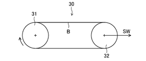
図11は、ベルト走行試験機30のプーリレイアウトを示す。
図11は、ベルト走行試験機30のプーリレイアウトを示す。
このベルト走行試験機30は、S8Mの歯形に対応する歯数22個の駆動プーリ31と、その右側方に設けられた同一構成の歯数22個の従動プーリ32とを有する。従動プーリ32は、軸荷重を負荷できるように左右可動に設けられている。
実施例及び比較例のそれぞれの歯付ベルトBについて、駆動プーリ31及び従動プーリ32に巻き掛け、従動プーリ32に右方に1000Nの軸定荷重SW(セットウエイト)を負荷してベルト張力を与えるとともに13N・mの回転トルクを負荷した後、駆動プーリ31を5000rpmで回転させてベルト走行させた。そして、定期的にベルト走行を停止して歯部の欠損、つまり、歯欠けの有無を確認し、歯欠けが発見された時点でベルト走行を終了し、それまでのベルト走行時間を歯欠け寿命とした。
(試験結果)
図12は、実施例及び比較例の歯欠け寿命を示す。
図12は、実施例及び比較例の歯欠け寿命を示す。
図12によれば、歯部側表面に架橋ポリエチレンで形成された表面被覆層が設けられた実施例は、表面被覆層が未架橋ポリエチレンで形成された比較例よりも、歯欠け寿命が約2倍も長いことが分かる。これは、実施例の表面被覆層を形成する架橋ポリエチレンが、ポリエチレンの分子同士が架橋されていることにより、耐摩耗性が著しく高められ、その結果、補強布の摩耗が抑制されて耐歯欠け性が向上するためであると考えられる。
本発明は、伝動ベルト及びその製造方法の技術分野について有用である。
B 歯付ベルト(伝動ベルト)
11 ベルト本体
13 補強布(表面被覆層)
14 表面被覆層
11 ベルト本体
13 補強布(表面被覆層)
14 表面被覆層
Claims (10)
- プーリ接触表面に表面被覆層が設けられた伝動ベルトであって、
前記表面被覆層は、ポリオレフィン分子同士が架橋された架橋ポリオレフィンで形成されている伝動ベルト。 - 請求項1に記載された伝動ベルトにおいて、
前記架橋ポリオレフィンの極限粘度が5dl/g以上50dl/g以下である伝動ベルト。 - 請求項1又は2に記載された伝動ベルトにおいて、
前記架橋ポリオレフィンが、平均分子量が50万以上の超高分子量ポリオレフィンが架橋したものである伝動ベルト。 - 請求項1乃至3のいずれかに記載された伝動ベルトにおいて、
前記表面被覆層が、前記架橋ポリオレフィンのシートで構成されている伝動ベルト。 - 請求項1乃至3のいずれかに記載された伝動ベルトにおいて、
前記表面被覆層が、多数の架橋ポリオレフィンの粒子が融着乃至密着した層で構成されている伝動ベルト。 - 請求項1乃至3のいずれかに記載された伝動ベルトにおいて、
前記表面被覆層が、多数の架橋ポリオレフィンの短繊維が融着乃至密着した層で構成されている伝動ベルト。 - 請求項1乃至3のいずれかに記載された伝動ベルトにおいて、
前記表面被覆層が、架橋ポリオレフィンの繊維で形成された布材で構成されている伝動ベルト。 - 請求項1乃至7のいずれかに記載された伝動ベルトにおいて、
エラストマーで形成されたベルト本体と、前記ベルト本体を被覆するように設けられた補強布と、を備え、
前記表面被覆層は、前記補強布の表面を被覆するように設けられている伝動ベルト。 - 請求項1乃至7のいずれかに記載された伝動ベルトにおいて、
エラストマーで形成されたベルト本体を備え、
前記表面被覆層は、前記ベルト本体の表面を被覆するように設けられている伝動ベルト。 - 請求項1乃至9のいずれかに記載された伝動ベルトの製造方法であって、
前記架橋ポリオレフィンを、ポリオレフィン分子同士が架橋されていない未架橋ポリオレフィンに放射線を照射することにより得る伝動ベルトの製造方法。
Priority Applications (1)
| Application Number | Priority Date | Filing Date | Title |
|---|---|---|---|
| JP2018530182A JPWO2019017100A1 (ja) | 2017-07-18 | 2018-06-06 | 伝動ベルト及びその製造方法 |
Applications Claiming Priority (2)
| Application Number | Priority Date | Filing Date | Title |
|---|---|---|---|
| JP2017139274 | 2017-07-18 | ||
| JP2017-139274 | 2017-07-18 |
Publications (1)
| Publication Number | Publication Date |
|---|---|
| WO2019017100A1 true WO2019017100A1 (ja) | 2019-01-24 |
Family
ID=65016451
Family Applications (1)
| Application Number | Title | Priority Date | Filing Date |
|---|---|---|---|
| PCT/JP2018/021693 Ceased WO2019017100A1 (ja) | 2017-07-18 | 2018-06-06 | 伝動ベルト及びその製造方法 |
Country Status (2)
| Country | Link |
|---|---|
| JP (1) | JPWO2019017100A1 (ja) |
| WO (1) | WO2019017100A1 (ja) |
Cited By (2)
| Publication number | Priority date | Publication date | Assignee | Title |
|---|---|---|---|---|
| JP2022006364A (ja) * | 2020-06-24 | 2022-01-13 | 株式会社豊田自動織機 | フォークリフトの荷役装置 |
| US20230136880A1 (en) * | 2020-03-16 | 2023-05-04 | Bayerische Motoren Werke Aktiengesellschaft | Steering System of a Vehicle |
Citations (1)
| Publication number | Priority date | Publication date | Assignee | Title |
|---|---|---|---|---|
| US20170122404A1 (en) * | 2014-06-17 | 2017-05-04 | Arntz Beteilgungs Gmbh & Co. Kg | Force transmission belt comprising a polyethylene coating |
-
2018
- 2018-06-06 JP JP2018530182A patent/JPWO2019017100A1/ja active Pending
- 2018-06-06 WO PCT/JP2018/021693 patent/WO2019017100A1/ja not_active Ceased
Patent Citations (1)
| Publication number | Priority date | Publication date | Assignee | Title |
|---|---|---|---|---|
| US20170122404A1 (en) * | 2014-06-17 | 2017-05-04 | Arntz Beteilgungs Gmbh & Co. Kg | Force transmission belt comprising a polyethylene coating |
Cited By (3)
| Publication number | Priority date | Publication date | Assignee | Title |
|---|---|---|---|---|
| US20230136880A1 (en) * | 2020-03-16 | 2023-05-04 | Bayerische Motoren Werke Aktiengesellschaft | Steering System of a Vehicle |
| JP2022006364A (ja) * | 2020-06-24 | 2022-01-13 | 株式会社豊田自動織機 | フォークリフトの荷役装置 |
| JP7342805B2 (ja) | 2020-06-24 | 2023-09-12 | 株式会社豊田自動織機 | フォークリフトの荷役装置 |
Also Published As
| Publication number | Publication date |
|---|---|
| JPWO2019017100A1 (ja) | 2019-07-18 |
Similar Documents
| Publication | Publication Date | Title |
|---|---|---|
| JP4748856B2 (ja) | ポリマーコア付きのスチールコード | |
| JP5914202B2 (ja) | 伝動ベルト用カバー布および歯付ベルト | |
| JP6059111B2 (ja) | 摩擦伝動ベルト | |
| CN105209245B (zh) | 用于制作具有用包封层处理过的张力构件的皮带的方法以及如此生产的皮带 | |
| CN110446880B (zh) | 摩擦传动带及其制造方法 | |
| JP6795466B2 (ja) | 伝動ベルト及びその製造方法 | |
| WO2017126324A1 (ja) | 摩擦伝動ベルト及びその製造方法 | |
| WO2019017100A1 (ja) | 伝動ベルト及びその製造方法 | |
| US3584516A (en) | Endless belts reinforced with braided strands | |
| TW201901060A (zh) | V型稜紋皮帶及其製造方法 | |
| US10975933B2 (en) | Transmission belt and method for producing same | |
| JP2017172691A (ja) | 摩擦伝動ベルト及びその製造方法 | |
| JP6383135B1 (ja) | 伝動ベルト及びその製造方法 | |
| JP6007353B2 (ja) | Vリブドベルト及びその製造方法、並びにベルト伝動装置 | |
| JPH0553977B2 (ja) | ||
| JP2017129255A (ja) | 摩擦伝動ベルト及びその製造方法 | |
| JP5669814B2 (ja) | 伝動ベルト | |
| JP2019007596A (ja) | 摩擦伝動ベルト及びその製造方法 | |
| JP2010255739A (ja) | 伝動ベルト | |
| JP4185701B2 (ja) | 歯付ベルト及びその製造方法 | |
| JP6530877B1 (ja) | 摩擦伝動ベルト | |
| WO2019193881A1 (ja) | 摩擦伝動ベルト | |
| JP3735084B2 (ja) | 歯付ベルト | |
| TW202503186A (zh) | 齒形帶 | |
| CN121701608A (zh) | 齿形带、以及齿形带的制造方法 |
Legal Events
| Date | Code | Title | Description |
|---|---|---|---|
| ENP | Entry into the national phase |
Ref document number: 2018530182 Country of ref document: JP Kind code of ref document: A |
|
| 121 | Ep: the epo has been informed by wipo that ep was designated in this application |
Ref document number: 18836220 Country of ref document: EP Kind code of ref document: A1 |
|
| NENP | Non-entry into the national phase |
Ref country code: DE |
|
| 122 | Ep: pct application non-entry in european phase |
Ref document number: 18836220 Country of ref document: EP Kind code of ref document: A1 |