WO2019017007A1 - 列車運転支援装置、列車運転支援システム、及び列車運転支援方法 - Google Patents
列車運転支援装置、列車運転支援システム、及び列車運転支援方法 Download PDFInfo
- Publication number
- WO2019017007A1 WO2019017007A1 PCT/JP2018/012235 JP2018012235W WO2019017007A1 WO 2019017007 A1 WO2019017007 A1 WO 2019017007A1 JP 2018012235 W JP2018012235 W JP 2018012235W WO 2019017007 A1 WO2019017007 A1 WO 2019017007A1
- Authority
- WO
- WIPO (PCT)
- Prior art keywords
- train
- information
- driving operation
- driving
- operation determination
- Prior art date
- Legal status (The legal status is an assumption and is not a legal conclusion. Google has not performed a legal analysis and makes no representation as to the accuracy of the status listed.)
- Ceased
Links
Images

Classifications
-
- B—PERFORMING OPERATIONS; TRANSPORTING
- B61—RAILWAYS
- B61L—GUIDING RAILWAY TRAFFIC; ENSURING THE SAFETY OF RAILWAY TRAFFIC
- B61L15/00—Indicators provided on the vehicle or train for signalling purposes
- B61L15/0058—On-board optimisation of vehicle or vehicle train operation
-
- B—PERFORMING OPERATIONS; TRANSPORTING
- B60—VEHICLES IN GENERAL
- B60L—PROPULSION OF ELECTRICALLY-PROPELLED VEHICLES; SUPPLYING ELECTRIC POWER FOR AUXILIARY EQUIPMENT OF ELECTRICALLY-PROPELLED VEHICLES; ELECTRODYNAMIC BRAKE SYSTEMS FOR VEHICLES IN GENERAL; MAGNETIC SUSPENSION OR LEVITATION FOR VEHICLES; MONITORING OPERATING VARIABLES OF ELECTRICALLY-PROPELLED VEHICLES; ELECTRIC SAFETY DEVICES FOR ELECTRICALLY-PROPELLED VEHICLES
- B60L15/00—Methods, circuits, or devices for controlling the traction-motor speed of electrically-propelled vehicles
- B60L15/20—Methods, circuits, or devices for controlling the traction-motor speed of electrically-propelled vehicles for control of the vehicle or its driving motor to achieve a desired performance, e.g. speed, torque, programmed variation of speed
- B60L15/2009—Methods, circuits, or devices for controlling the traction-motor speed of electrically-propelled vehicles for control of the vehicle or its driving motor to achieve a desired performance, e.g. speed, torque, programmed variation of speed for braking
-
- B—PERFORMING OPERATIONS; TRANSPORTING
- B61—RAILWAYS
- B61L—GUIDING RAILWAY TRAFFIC; ENSURING THE SAFETY OF RAILWAY TRAFFIC
- B61L15/00—Indicators provided on the vehicle or train for signalling purposes
- B61L15/0062—On-board target speed calculation or supervision
-
- B—PERFORMING OPERATIONS; TRANSPORTING
- B61—RAILWAYS
- B61L—GUIDING RAILWAY TRAFFIC; ENSURING THE SAFETY OF RAILWAY TRAFFIC
- B61L27/00—Central railway traffic control systems; Trackside control; Communication systems specially adapted therefor
- B61L27/10—Operations, e.g. scheduling or time tables
- B61L27/14—Following schedules
-
- B—PERFORMING OPERATIONS; TRANSPORTING
- B61—RAILWAYS
- B61L—GUIDING RAILWAY TRAFFIC; ENSURING THE SAFETY OF RAILWAY TRAFFIC
- B61L15/00—Indicators provided on the vehicle or train for signalling purposes
- B61L15/0072—On-board train data handling
-
- B—PERFORMING OPERATIONS; TRANSPORTING
- B61—RAILWAYS
- B61L—GUIDING RAILWAY TRAFFIC; ENSURING THE SAFETY OF RAILWAY TRAFFIC
- B61L27/00—Central railway traffic control systems; Trackside control; Communication systems specially adapted therefor
- B61L27/60—Testing or simulation
-
- Y—GENERAL TAGGING OF NEW TECHNOLOGICAL DEVELOPMENTS; GENERAL TAGGING OF CROSS-SECTIONAL TECHNOLOGIES SPANNING OVER SEVERAL SECTIONS OF THE IPC; TECHNICAL SUBJECTS COVERED BY FORMER USPC CROSS-REFERENCE ART COLLECTIONS [XRACs] AND DIGESTS
- Y02—TECHNOLOGIES OR APPLICATIONS FOR MITIGATION OR ADAPTATION AGAINST CLIMATE CHANGE
- Y02T—CLIMATE CHANGE MITIGATION TECHNOLOGIES RELATED TO TRANSPORTATION
- Y02T10/00—Road transport of goods or passengers
- Y02T10/60—Other road transportation technologies with climate change mitigation effect
- Y02T10/72—Electric energy management in electromobility
-
- Y—GENERAL TAGGING OF NEW TECHNOLOGICAL DEVELOPMENTS; GENERAL TAGGING OF CROSS-SECTIONAL TECHNOLOGIES SPANNING OVER SEVERAL SECTIONS OF THE IPC; TECHNICAL SUBJECTS COVERED BY FORMER USPC CROSS-REFERENCE ART COLLECTIONS [XRACs] AND DIGESTS
- Y02—TECHNOLOGIES OR APPLICATIONS FOR MITIGATION OR ADAPTATION AGAINST CLIMATE CHANGE
- Y02T—CLIMATE CHANGE MITIGATION TECHNOLOGIES RELATED TO TRANSPORTATION
- Y02T90/00—Enabling technologies or technologies with a potential or indirect contribution to GHG emissions mitigation
- Y02T90/10—Technologies relating to charging of electric vehicles
- Y02T90/16—Information or communication technologies improving the operation of electric vehicles
Definitions
- the present invention relates to a train operation support device, a train operation support system, and a train operation support method, and is suitably applied to a train operation support device, a train operation support system, and a train operation support method for determining an appropriate operation operation of a train. It is a thing.
- the system supports a driver's operation operation by providing information such as a train control function in which the system automatically executes an operation operation calculated by a computer and a switching point of the operation operation.
- a train control function in which the system automatically executes an operation operation calculated by a computer and a switching point of the operation operation.
- an apparatus having a train operation support function for securing regularity and improving the energy saving effect has been proposed and put into practical use.
- the train control function and the train driving support function need to determine information on desirable driving operation at least immediately before the driving operation is carried out.
- a train operation control system of Patent Document 1 As a prior art of such a technical field, for example, a train operation control system of Patent Document 1 is disclosed.
- the train operation control system disclosed in Patent Document 1 aims to make it possible to avoid the deviation of the position / speed of the train with respect to the run curve to be re-created, and the ground device operates the train after the predicted set time has elapsed.
- One feature of the present invention is to provide a run curve generation unit that generates a run curve from the time after the set time has elapsed using the position / speed information of the above.
- traveling of the train in the railway system is affected by fluctuation factors such as overhead wire voltage and boarding rate which fluctuate from traveling to traveling, and its acceleration and deceleration change.
- fluctuation factors such as overhead wire voltage and boarding rate which fluctuate from traveling to traveling, and its acceleration and deceleration change.
- different trains can not be run according to the travel pattern of the same position and speed as the travel pattern of a given train, and even if the switching timing of the driving operation is calculated in advance, the operation can not be reproduced It was difficult. That is, it is necessary to determine an appropriate driving operation in real time in order to realize traveling that achieves the goals of the system such as securing regularity and improving energy saving effects while responding to such fluctuation factors.
- the calculation load of the on-board equipment can be reduced by performing the traveling calculation on the on-ground calculation device without performing on-the-board equipment.
- the traveling pattern for a large number of conditions is always calculated on the ground. The need to transmit from the device increases the load on communication resources. As a result, under a device in which communication resources are limited, sufficient communication conditions can not be maintained, and there is a risk that an appropriate driving operation decision can not be made.
- the present invention has been made in consideration of the above points, and in a train system having limited computational resources and communication resources, a train driving support device capable of supporting the determination of driving operation that can be expected for securing on-time performance and energy saving effect. , A train driving support system, and a train driving support method.
- the present invention provides a judgment criterion of driving operation which constitutes one of predetermined input information to a train system which determines the driving operation of a train based on predetermined input information. It is a train driving support device that provides driving operation determination table data information, and affects the travel of the train from the overall table creation unit that creates the overall table information by the table information on the entire target section where the train travels Limiting table information of an area in which switching of the driving operation is performed within the fluctuation range of the external factor giving the table area, and outputting the limited table information as driving operation determination table data information;
- a train driving support device characterized by the present invention is provided.
- the present invention is a train driving support system for supporting the driving operation of a train, and shows a train position detection unit that outputs train position information indicating the position of the train Determination of driving operation for each train position and train speed based on the train speed detection unit that outputs train speed information and external factor range information that defines the fluctuation range of external factors that affect the travel of the train Driving operation that determines driving operation based on a driving operation determination table data generating unit that generates and outputs driving operation determination table data information that provides a standard, train position information, train speed information, and driving operation determination table data information
- a train operation support system comprising: a determination unit.
- the driving operation determination table data generating unit generates overall table information based on the table information on the entire target section in which the train travels, and the fluctuation range of external factors from the overall table information
- the table area limitation part which limits the table information of the area
- a train driving support method by a train driving support system for supporting a train driving operation comprising: a train position detection step of outputting train position information indicating a position of the train; Based on the train speed detection step of outputting the train speed information indicating the speed of the train and the external factor range information defining the fluctuation range of the external factor affecting the travel of the train
- the driving operation judgment table data generating step for generating and outputting the driving operation judgment table data information to the driving operation, the driving operation based on the train position information, the train speed information, and the driving operation judgment table data information
- a driving operation determining step of determining a train driving support method.
- operation operation is performed inside, and outputting the said limited table information as driving operation determination table data information is included.
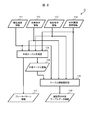
- FIG. 1 is a functional configuration diagram of a train operation support system according to an embodiment of the present invention.
- the train driving support system 1 is a system that controls the operation of the train 10 and is realized by, for example, an on-board device mounted on the train 10.
- the train driving support system 1 includes a driving operation determination table data creation unit 11, a train position detection unit 12, a train speed detection unit 13, a driving operation determination unit 14, and a drive control unit 15 and the display unit 16.
- the driving operation determination table data creation unit 11 has a function of calculating driving operation determination table data information and brake pattern information which are information necessary to determine the driving operation (providing the determination reference of the driving operation), The driving operation determination table data information and the brake pattern information obtained by the above are output to the driving operation determination unit 14.
- the driving operation determination table data creation unit 11 corresponds to the train driving support device of the present invention, and can be realized by, for example, a computer of an on-board device mounted on the train 10.
- the driving operation determination table data creation unit 11 can also be realized by a computing device installed outside the train 10, for example, on the ground, and in this case, the driving operation determination calculated by the driving operation determination table data creation unit 11 Table data information and brake pattern information are transmitted to the train 10.
- the train position detection unit 12 has a function of detecting the position of the train 10, and outputs the detected train position to the driving operation determination unit 14.
- the train position detection unit 12 is, for example, a train position detection device using a track circuit, or another general positioning device.
- the train speed detection unit 13 has a function of detecting the speed of the train 10, and outputs the detected train speed to the driving operation determination unit 14.
- the train speed detection unit 13 is, for example, a speed generator.
- the driving operation determination unit 14 performs driving including information related to the driving operation to be performed by the train 10 based on the information (driving operation determination table data information, brake pattern information, train position information, and train speed information) input from each unit. It has a function of determining operation information.
- the driving operation determination unit 14 outputs the determined driving operation information to the drive device control unit 15 and the display unit 16.
- the driving operation determination unit 14 can be realized, for example, by a computer of an on-board device mounted on the train 10.
- the drive control unit 15 has a function of performing drive control of a motor, an engine, etc., and the train drive support system 1 is intended by performing drive control based on the drive operation information output from the drive operation determination unit 14. To realize the train travelling.
- the drive control unit 15 is, for example, a drive control panel of the train 10.
- the display unit 16 has a display function, and displays information on train travel determined by the train driving support system 1 based on the driving operation information output from the driving operation determination unit 14.
- the display unit 16 is realized by, for example, a general display, a display panel, or the like, and may be a monitor of a cab of the train 10, a terminal held by an operator, or the like.
- the driving operation determination unit 14 determines the driving operation information regarding the driving operation to be assisted, but the driving operation of the train 10 is performed based on the driving operation information.
- the travel pattern in the case is referred to as a travel pattern according to the present embodiment.
- the travel pattern represents the speed at each position where the train travels, in other words, the relationship between the position and the speed in the travel section of the train.
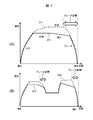
- FIG. 2 is a diagram for explaining an image of a travel pattern by the train driving support system according to the present embodiment.
- a traveling pattern in a traveling section from the station A to a station B is illustrated
- a traveling pattern in a traveling section from the station B to a station C is illustrated.
- examples of travel patterns of the train 10 by the train driving support system 1 according to the present embodiment are represented by solid lines 221 and 222.
- the travel pattern by "fastest travel” is represented by the broken line 211, 212 as an example of the conventional travel pattern for comparison.
- the "fastest travel” means that the train 10 travels the fastest while observing the speed limit (within the speed limit tolerance). For example, in the case of FIG. 2 (A), after leaving the station A, the vehicle is accelerated (power running) while not exceeding the upper limit of the speed limit and trains can not accelerate any more (the upper limit of the speed limit is exceeded) The constant speed operation to maintain the speed is performed, and when approaching the station B at the stop point, the speed reduction operation is performed using the brake. According to such a travel pattern of the fastest travel, the train 10 can arrive at the stop point in the shortest time while complying with the speed limit. Also, as shown in FIG.
- the driving operation for performing the traveling pattern by such fastest traveling can be determined based on constraints such as the vehicle performance and the route environment.
- constraints such as the vehicle performance and the route environment.
- the train operation schedule is planned to have some time allowance, and if the driver performs the driving operation in the travel pattern by the fastest travel, it will arrive earlier than the planned time, so securing the on-time property.
- running pattern in a brake area is defined as a brake pattern.
- the brake pattern can be used to determine the necessity of the brake operation during driving, and in particular, if the speed at a certain position is present on or above the brake pattern It can be determined that a brake operation is necessary.
- the train driving support system 1 can calculate the driving operation of the train 10 that can be expected for the energy saving effect while securing the regularity.
- the travel patterns solid lines 221 and 222
- the travel pattern according to the present embodiment is compared to the travel pattern for the fastest travel, in the execution of the coasting operation and at a speed less than the speed limit. There are two differences, switching to constant speed operation or coasting operation.
- the solid line 221 is similar to the dashed line 211 of the fastest run in that power running is performed after leaving the station A, but the upper limit of the speed limit is reached Even before, it has been switched to constant speed operation. Further, the point that coasting operation is performed before entering the brake section after the constant speed operation is also different from the broken line 211, and after coasting operation, decelerating operation using the brake is performed. This feature is also seen in FIG. 2 (B) provided with a slowing interval.
- coasting operation means driving by coasting running the train 10 by inertia without acceleration by the drive device or deceleration by the brake, and travels by kinetic energy that the train 10 has had so far.
- the present travel pattern when the train 10 is decelerated, not only the deceleration operation by the brake is performed, but the rapid deceleration is avoided in order to avoid the rapid deceleration by sandwiching the constant speed operation and the coasting operation. Can be expected to have the effect of reducing the discomfort and pressure caused by
- the driving operation determination unit 14 determines the switching timing of each driving operation using the driving operation determination table data information for switching of each driving operation in the travel pattern according to the present embodiment. Therefore, in the next chapter, processing (driving operation determination processing) by the driving operation determination unit 14 will be described in detail.
- the driving operation determination table data information is used in the driving operation determination process by the driving operation determination unit 14.
- the driving operation determination table data information includes table information (constant speed table information) related to constant speed operation and table information (overhead table information) related to coasting operation. Also, both table information is data that can be handled in the same table format.
- driving operation determination table data information (constant speed table information, coasting table information) will be described with reference to FIGS. 3 and 4.
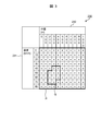
- FIG. 3 is a diagram (part 1) for explaining an example of driving operation determination table data information.
- the table 230 shown in FIG. 3 is an image example of table information (constant speed table information or coasting table information) included in the driving operation determination table data information.
- the table 230 is represented by two-dimensional data according to the train speed 231 and the position 232.
- the speed 231 up to the maximum speed by 10 km / h
- position 232 dividing the horizontal axis from the departure point to the arrival point in 100 m intervals.
- two-dimensional data having lattice points.
- the table value corresponding to the speed 231 and the position 232 is described in each lattice point.
- the driving operation determination table data creation unit 11 may actually perform driving operation in a range (for example, Since the driving operation determination table data information (constant speed table information, coasting table information) limited to the region Q) is created and output to the driving operation determination unit 14, the processing load by the driving operation determination unit 14 can be reduced, It is possible to reduce the consumption of computing resources.
- a range for example, Since the driving operation determination table data information (constant speed table information, coasting table information) limited to the region Q) is created and output to the driving operation determination unit 14, the processing load by the driving operation determination unit 14 can be reduced, It is possible to reduce the consumption of computing resources.
- the table information (constant speed table information or coasting table information) included in the driving operation determination table data information does not necessarily have to be configured with two-dimensional data, and may have another data configuration.
- FIG. 4 is a diagram (part 2) for explaining an example of the driving operation determination table data information.
- the table information of the driving operation determination table data information may have a data configuration in which a combination of each element (position 241, speed 242, table value 243) is listed.
- individual table values can be used to determine the switching timing of the driving operation by the driving operation determination unit 14 Set to contain information.
- the driving operation determination unit 14 determines the switching timing of the driving operation to the constant speed operation as follows.
- T the remaining time calculated as the difference between the current time and the arrival target time
- the driving operation determination unit 14 determines the switching timing of the driving operation to the constant speed operation as follows.
- desirable judgment results can be obtained to achieve the goals of the system such as on-time performance and energy saving. That is, when T is 72 seconds or more, it is determined to switch the current driving operation to constant speed driving, and when T is less than 72 seconds, the original driving operation remains unchanged without switching the driving operation. It is preferable to determine to maintain.
- constant speed table information and coasting table information are set for each station, for example, by reading information corresponding to the current state consisting of the train position and the train speed from the constant speed table information, the constant state for the current state is determined.
- speed table values In this reading, when the grid point corresponding to the current state is not defined in the constant speed table information, one grid point closest to the current state may be selected and defined using the table value of the grid point. .
- a table value may be defined based on internal divisions in the direction of position and velocity from four intersection points of the position and velocity surrounding the current state.
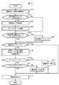
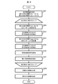
- FIG. 5 is a flowchart showing an example of the processing procedure of the driving operation determination processing.
- the brake pattern information and the driving operation determination table data information output from the driving operation determination table data creation unit 11, the train position and the train speed detection unit output from the train position detection unit 12 The driving operation determination unit 14 determines the driving operation based on the train speed output from 13.
- step S101 the driving operation is set to the immediately preceding driving operation.
- step S102 the relationship between the current train position and the end point of the current brake pattern is determined.
- the current train position can be identified by the train position output from the train position detection unit 12, and the termination point of the brake pattern means the point closest to the arrival point among the brake patterns.
- the driving operation determination unit 14 determines whether the current train position has exceeded the end point of the brake pattern. If the current train position is beyond the end point of the brake pattern, ie, the current train position is closer to the arrival point than the end point (YES in step S102), the process proceeds to step S103. If the current train position does not exceed the end point of the brake pattern (NO in step S102), the process proceeds to step S105.
- step S103 since the current train position is beyond the end point of the brake pattern, the train operation can be accelerated within the range of the speed limit. It sets to "the fastest driving
- step S104 the driving operation determination unit 14 resets the current brake pattern.
- the brake pattern present after the current train position is selected as the brake pattern after resetting. Thereafter, the process proceeds to step S105.
- step S105 it is determined whether the current train position and the train speed exist below by the brake pattern by determining the following two determination items regarding the current train position and the relationship between the train speed and the brake pattern. Determine if Specifically, the first judgment item is whether or not the brake pattern is defined at the current train position, and the second judgment item is that the current train speed is the brake pattern at the current train position. It is whether or not it is less than the set speed limit.
- the determination result of the first or second determination item is true (YES in step S105)
- the determination result of the first or second determination item is false in the process of step S107. (NO in step S105), the process proceeds to step S106.
- step S106 the brake pattern is defined for the current train position in the determination of step S105, and it is determined that the current train speed is equal to or higher than the speed limit of the brake pattern. It is determined that decelerating operation using a brake is necessary to reduce the speed quickly. Therefore, in step S106, the driving operation is set to "brake", and the process proceeds to step S107.
- step S107 it is determined whether the driving operation is set other than “brake”. If the driving operation is set to other than “brake” (YES in step S107), the process proceeds to step S108. If the driving operation is set to "brake” (NO in step S107), the process proceeds to step S113. The driving operation currently set (in this case, "brake") is output as driving operation information, and the driving operation determination process is ended.
- step S108 a table value corresponding to the current train position and train speed is read from the constant speed table information (see FIGS. 3 and 4) included in the driving operation determination table data information, and is set as a constant speed table value T1.
- T1 ⁇ 1.
- the remaining time T up to the target arrival time is calculated based on the current time and the target arrival time.
- step S109 it is determined whether or not the coasting operation can be selected as the driving operation. Specifically, in step S109, it is determined whether the judgment formula "T2 is negative or T ⁇ T2" is true or false using the remaining time T and the inertia line table value T2 obtained in step S108. If the determination result is true (YES in step S109), this means that the coasting operation can not be selected, and the process proceeds to step S111. If the determination result is false (NO in step S109), this means that the coasting operation can be selected, and the process proceeds to step S110.
- step S110 the coasting table value T2 is not negative in the determination of step S109 (that is, coasting table values corresponding to the current train position and train speed are defined in the coasting table information), and the remaining time T is Since it is determined that the coasting table value T2 or more (that is, there is a remaining time in which the coasting operation can be performed), it is determined that the coasting operation can be selected. Therefore, in step S110, the driving operation determination unit 14 sets the driving operation to "coasting". After step S110, the process proceeds to step S113, and the currently set driving operation (in this case, “coasting”) is output as driving operation information, and the driving operation determination process is ended.
- the currently set driving operation in this case, “coasting”
- step S111 since it is determined that the operation operation of the coasting operation can not be selected by the determination of step S109, it is determined whether or not the constant speed operation can be selected as the operation operation. Specifically, in step S111, using the remaining time T and the constant speed table value T1 obtained in step S108, it is determined whether the determination formula "T1 is negative or T ⁇ T1" is true or false. If the determination result is true (YES in step S111), this means that the constant speed operation can not be selected, so the process proceeds to step S113, and the driving operation currently set (in this case, "fastest operation") is operated. It outputs as information and ends the driving operation determination process. On the other hand, if the determination result in step S109 is false (NO in step S111), this means that the constant speed operation can be selected, and the process proceeds to step S112.
- step S112 the constant speed table value T1 is not negative in the determination of step S111 (that is, the constant speed table value corresponding to the current train position / train speed is defined in the constant speed table information), and Since it is determined that the remaining time T is equal to or greater than the constant speed table value T1 (that is, there is a remaining time that can perform constant speed operation), it is determined that the constant speed operation can be selected. Therefore, in step S112, the driving operation determination unit 14 sets the driving operation to "constant speed". After step S112, the process proceeds to step S113, and the currently set driving operation (in this case, "constant speed”) is output as driving operation information, and the driving operation determination process is ended.
- the currently set driving operation in this case, "constant speed”
- the driving operation determination unit 14 determines whether to switch to each driving operation based on the input various information, and is appropriately performed. Driving maneuvers can be determined.
- a table area limiting unit 118 (see FIG. 6) of the driving operation determination table data creating unit 11 described later performs driving operation determination processing by the driving operation determination unit 14 It has a function to execute traveling simulation using a similar algorithm. That is, the table region limiting unit 118 of the driving operation determination table data creation unit 11 exemplifies the driving operation by the processing similar to the driving operation determination processing illustrated in FIG. It is possible to simulate the appropriate driving pattern of the present invention including constant speed operation and coasting operation as described above. The detailed processing by the table area limiting unit 118 will be described in detail in FIG.
- FIG. 6 is a view showing a configuration example of a driving operation determination table data creation unit.
- the driving operation determination table data creation unit 11 is a train driving support device that creates the brake pattern information and the driving operation determination table data information necessary for determining the driving operation in the driving operation determination unit 14.
- the driving operation determination table data creation unit 11 is configured to include an entire table creation unit 115 and a table area limitation unit 118.
- the overall table creation unit 115 calculates the overall table information 116 and the brake pattern information 117 in the entire target section, using the speed limit information 111, the train condition information 112, the topography condition information 113, and the external factor range information 114 as input information.
- the table area limiting unit 118 generates the driving operation determination table data information 119 using the speed limit information 111, the train condition information 112, the terrain condition information 113, the external factor range information 114, and the entire table information 116 as input information.
- the speed limit information 111 the train condition information 112, the terrain condition information 113, and the external factor range information 114 as input information will be described.
- the speed limit information 111 is information defined regarding the speed limit of the train 10, and includes information on the start position, the end position, and the speed limit of each speed limit section.
- the speed limit information included in the speed limit information 111 is temporarily valid due to the influence of the weather, construction near the route, etc., and the speed limit information that is always effective due to the curve, the slope, the line arrangement, etc. There may be speed limit information.
- the train condition information 112 is information necessary to reproduce the physical behavior of the train 10. Specifically, for example, the total weight of the train 10, the train length, the tension, the braking force, the efficiency at the time of powering, And information such as the efficiency at the time of braking.
- the terrain condition information 113 is information of a route or a diagram necessary for generating a traveling pattern, and specifically, for example, location information of a departure point, location information of an arrival point, gradient information between the departure point and the arrival point, departure It includes curve information from a point to an arrival point, and information on predetermined travel times to be filled between the departure point and the arrival point.
- the external factor range information 114 is information indicating a range or a representative value of external factor values that may change each time the train 10 travels among physical quantities that affect the movement of the train 10.
- Specific physical quantities that may be included in the external factor range information 114 include, for example, information on boarding ratio, variation range information on overhead wire voltage, wind direction and wind speed information that affects the running resistance of the train 10, or transmission delay or control delay
- the external factor range information 114 includes information on the range of all or part of these physical quantities.
- Each piece of information included in the external factor range information 114 may be in any manner as long as conditions are set such that the variation range is determined for each train (including different travel opportunities by the same train 10). It can be assumed.
- the external factor range information 114 may give information on the entire range that each physical quantity can take, such as “ride rate is 0% to 250%”.
- the external factor range information 114 may provide range information corresponding to each condition related to the travel of the train 10.
- the holding manner of the range information regarding each physical quantity in the external factor range information 114 does not have to be unique, and is recorded in an independent form for each physical quantity It is also good.
- the boarding rate may be recorded as information in the entire possible range
- the overhead line voltage may be recorded for each train number
- the wind speed may be recorded for each time zone.
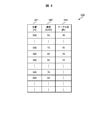
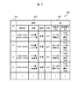
- FIG. 7 is a diagram showing an example of external factor range information.
- the table 250 shown in FIG. 7 is an example of the external factor range information 114 according to the assignment mode of the second example.
- No. 251 is a number collectively indicating a combination of one or more conditions described in the condition 252, and corresponds to "traveling condition" in FIG. 8 described later.
- the condition 252 conditions relating to the travel of the train 10 are described, and specifically, a travel time (time zone), a travel section (section), an operation type (type), and a travel direction (direction) are illustrated.
- range information of the external factor value for the train satisfying the condition 252 is described, and specifically, the boarding rate and the overhead line voltage are illustrated.
- "travel conditions" of No. 251 are not classified as what put together a plurality of conditions like the condition 252 of FIG. 7, but, for example, for each individual train number on the timetable of trains Range information of external factor values may be indicated and classified into “travel conditions”.
- the overall table creation unit 115 that creates the overall table information 116 and the brake pattern information 117 using the above-described input information will be described.
- the whole table creation unit 115 uses the input information (speed limit information 111, train condition information 112, terrain condition information 113, and external factor range information 114) to set “each position between the departure point of the train 10 and the arrival point.
- the information on the remaining time in which the driving operation should be switched is calculated, table information (constant speed table information, coasting table information) corresponding to the entire target section is created, and output as overall table information 116.
- “each position” means a train position where it is determined whether or not to switch driving operation by the driving operation determination process of the driving operation determination unit 14, and the overall table creation unit 115 operates for each train position. Calculate the remaining time to switch operations.
- overall table creation section 115 calculates a series of brake position / speed in a section requiring a brake between the departure point of train 10 and the arrival point using the above input information, and outputs it as brake pattern information 117. .
- the entire table creation unit 115 calculates and outputs information on the entire target section.
- the entire table information 116 on the entire target section may be, for example, the range information of the area P in FIG.
- the table area limiting unit 118 for creating the driving operation determination table data information 119 using the input information and the whole table information 116 will be described.
- the table area limiting unit 118 estimates range information in which the driving operation may actually be performed based on the external factor range information 114, and table information (constant speed table information and coasting table within the estimated range). Information) is generated and output as driving operation determination table data information 119.
- FIG. 8 is a flowchart showing an example of a processing procedure of driving operation determination table data creation processing.
- the driving operation determination table data creation processing illustrated in FIG. 8 is processing for the table region limiting unit 118 to create the driving operation determination table data information 119.
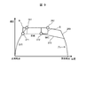
- FIG. 9 is a figure for demonstrating the image of simulation of the driving
- the driving operation determination table data creation processing will be described along the processing procedure illustrated in FIG. 8 as needed, referring to the image illustrated in FIG.
- the table region limiting unit 118 includes the constant speed operation and the coasting operation according to the driving operation determination process (see FIG. 5) by the same algorithm as the driving operation determination unit 14.
- the driving simulation function is capable of calculating an appropriate driving pattern (for example, solid lines 221 and 222 in FIG. 2).
- the table area limiting unit 118 determines an allowable traveling time width before limiting the table information (the constant speed table information and the coasting table information) to be the driving operation determination table data information 119.
- a predetermined allowable range may be given to the target traveling time (target traveling time), and this allowable range corresponds to the "traveling time width".
- step S201 specifically, for example, assuming that the travel time width is represented by Tmin to Tmax, the minimum when the target travel time from the calculation start point to the arrival target position is T0 seconds and the allowable width is 10 seconds
- the traveling time Tmin of the above is "T0-10", and the maximum traveling time Tmax is "T0 + 10".
- the allowable range does not necessarily have to be the same in size.
- the table area limiting unit 118 thus set determines information of the table area to be utilized in the range of Tmin to Tmax in the subsequent processing.
- the table area limiting unit 118 repeatedly executes the processing of steps S202 to S207 for each of the traveling conditions (for example, No 251 in FIG. 7) given from the external factor range information 114 (loop processing).
- a power running pattern in combination of fluctuation conditions is calculated. Since variations in external factors affect acceleration, the powering patterns differ in each combination.
- processing is performed to check an area in which switching to constant speed operation is performed.
- step S202 the target travel time at the time of departure is set to Tmin, and constant-speed driving is performed while calculating the driving operation by the driving operation determination process (see FIG. 5) by the same algorithm as the driving operation determination unit 14. And run a driving simulation to calculate the appropriate driving pattern of the present invention, including coasting.
- a traveling pattern 260 (broken line 260 in the image of FIG. 9) is calculated by this traveling simulation.
- step S203 in the travel pattern 260 calculated in step S202, a point at which switching from the power running operation to the constant speed operation is performed (corresponding to point 261 in the image of FIG. And a point at which switching to coasting operation is performed (corresponding to point 262 in the image of FIG. 9 and hereinafter referred to as coasting start point 262).
- step S204 the target travel time at the time of departure is set to Tmax, and the driving operation is calculated by the driving operation determination process (see FIG. 5) by the same algorithm as the driving operation determination unit 14 as in step S202.
- running simulation is performed to calculate an appropriate running pattern of the present invention including constant speed operation and coasting operation.
- a traveling pattern 270 (broken line 270 in the image of FIG. 9) is calculated by this traveling simulation.
- step S205 switching to constant speed operation is performed for the travel pattern 270 calculated in step S204 (corresponding to point 271 in the image of FIG. 9 and hereinafter referred to as powering end point 271), and coasting operation
- the point to be switched to (corresponding to the point 272 in the image of FIG. 9 and hereinafter referred to as the crawling start point 272) is extracted.
- step S206 the constant speed switching area R is calculated and recorded using the powering end point 261 extracted in step S203 and the powering end point 271 extracted in step S205.
- a method of calculating the constant speed switching area R will be described with reference to FIG. 9.
- a power running end point 261 and a power running end point 271 are provided at diagonal corners, and a rectangle in which each side is parallel to the axis is created. When this occurs, the area enclosed by the rectangle becomes the constant speed switching area R.
- step S207 the coasting switching area S is calculated and recorded using the coasting start point 262 extracted in step S203 and the coasting start point 272 extracted in step S205.
- the method of calculating the flooding switching area S will be described with reference to FIG. 9.
- a crawling start point 262 and a crawling start point 272 are placed at diagonal corners and a rectangle in which each side is parallel to the axis is created.
- the area surrounded by the rectangle is the coasting switching area S.
- the constant speed switching area R and the coasting switching area S under the traveling conditions selected in the loop processing are calculated and recorded by the processing of steps S202 to S207, and all the loop processing is performed, so that the external factor range information 114
- the constant speed switching area R and the coasting switching area S are calculated and recorded for all combinations of external factors (traveling conditions) given by.
- steps S208 and S209 using the constant speed switching area R and the coasting switching area S obtained by the loop processing, the output area of the constant speed table information and the output area of the coasting table information are determined.
- step S208 the union of constant speed switching regions R calculated for each combination of external factors (traveling conditions) by the above loop processing is converted to constant speed operation within the fluctuation range of external factors. It is determined that there is a possibility that switching will be performed, and it is decided to be an output area of constant speed table information.
- step S209 the union of the coasting switching area S calculated for each combination of external factors (traveling conditions) by the above-mentioned loop processing is switched to constant speed operation within the variation range of the external factors. It is determined that there is a possible area, and it is decided to be an output area of overhead table information.
- the processing of steps S201 to S208 is performed, so that the driving operation determination table data information 119 (the constant speed table information and the coasting table information)
- the output area can be limited to the range information in which the driving operation may actually be performed in consideration of the fluctuation range of the external factor, not the information (the whole table information 116).
- the driving operation determination table data information 119 based on the range information whose output area is limited may be, for example, the range information of the area Q in FIG. 3.
- the driving operation determination table data creation unit 11 generates the driving operation determination table data information 119 (constant speed table information and coasting table information) created by the table area limiting unit 118 and the brake pattern information created by the whole table creation unit 115. And 117 to the driving operation determination unit 14 (transmission).
- the driving operation determination table data creation unit 11 transmits only the driving operation determination table information (constant speed table information and coasting table information) included in the limited area to the driving operation determination unit 14. Since the table information transmitted in this manner can limit the output range of the information to be transmitted as compared to the case where the information on all lattice points regarding the train position and the train speed is transmitted (area P of FIG.
- the data volume of pattern information to be transmitted can be reduced (see area Q). Then, even if the resource of the communication path between the driving operation determination table data creating unit 11 and the driving operation determining unit 14 is restricted by the reduction of the data capacity of the pattern information, the processing before the switching of the driving operation is performed. It becomes possible to transmit pattern information at timing.
- the train operation support system 1 determines a traveling pattern (appropriate traveling pattern according to the present invention) incorporating switching of the driving operation of the constant speed operation and the coasting operation based on the input information. Control of the train according to the goals of the train system.
- the planning time It can be made to arrive at the stop point by time (secure on-time operation).
- a great energy saving effect can be expected by suppressing the acceleration to the maximum speed and adopting coasting operation.
- by putting constant speed operation or coasting operation at the time of deceleration it is possible to expect an effect of reducing discomfort and pressure feeling due to rapid deceleration and improving a passenger's ride comfort.
- the driving operation determination table data creation unit 11 determines both the switching timing to constant speed driving and the switching timing to coasting driving.
- the present invention is not limited thereto.
- the train driving support device may perform calculation to limit the output area of the driving operation determination table information only at one of the driving switching timings, and the effect of the present invention can be obtained in such a case as well. You can get it.
- the driving operation determination unit 14 determines an appropriate traveling pattern (such as switching of the driving operation) in the actual traveling, while the driving operation determination table data creation unit 11 is external If a factor is given in advance, the traveling pattern of each traveling condition is simulated based on the combination (traveling condition), and driving operation determination table data information with a limited output range is created and output.
- the driving operation determination table data creation unit 11 has some advance in advance (specifically, , As long as the range of the external factor value given by the external factor range information 114 or the time difference that can guarantee that the representative value is the information adapted to the current condition), and create the driving operation determination table data information You may Therefore, as long as the driving operation determination table data creation unit 11 is configured to be able to communicate the created information (the driving operation determination table data information and the brake pattern information) to the driving operation determination unit 14, the other operation of the train driving support system 1 It may be realized by a device different from the configuration of.
- the transmission means from the driving operation determination table data creation unit 11 to the driving operation determination unit 14 may be a wired communication device on the car, or even using the wireless function installed in each device Well, the installation place and transmission means are not limited.
- the train system does not change the device configuration for realizing the other configuration of the train driving support system 1. Only the train driving support device can be additionally mounted, and the function addition to the train system becomes easy.
- the train driving support device may be configured to include the display unit 16.
- the train driving support system 1 includes the drive control unit 15 and the display unit 16 as a configuration in which the driving operation information calculated by the driving operation determination unit 14 is output.
- the system that performs train control based on the driving operation information calculated by the operation determination unit 14 may be any configuration that outputs the driving operation information to the drive device control unit 15, and does not include the display unit 16 It is also good.
- the driving operation information is output to the display unit 16 and the driving operation information is not output to the driving device control unit 15 (or the driving device control unit 15 is not included) It may be When configured in this manner, the driver can properly operate the present invention by outputting driving operation information to the display unit 16 such as a monitor of the cab of the train 10 or a terminal held by the driver of the train 10 or the like.
- a driving operation method (such as switching timing of the driving operation) for realizing the traveling pattern can be recognized.
- the driver can realize the appropriate travel pattern of the present invention by driving the train 10 according to the driving operation method, the train driving support device, the train driving support system, and the train driving support method according to the present invention According to this, it is possible to obtain the effect of train operation support that can be expected to secure on-time performance and save energy.
- control lines and information lines indicate what is considered to be necessary for the description, and not all control lines and information lines in the product are necessarily shown. It may be considered that almost all configurations are mutually connected in the implementation.
Landscapes
- Engineering & Computer Science (AREA)
- Mechanical Engineering (AREA)
- Power Engineering (AREA)
- Transportation (AREA)
- Train Traffic Observation, Control, And Security (AREA)
- Electric Propulsion And Braking For Vehicles (AREA)
Priority Applications (1)
| Application Number | Priority Date | Filing Date | Title |
|---|---|---|---|
| EP18835604.2A EP3656600B1 (en) | 2017-07-20 | 2018-03-26 | Driving operation determination table data creation unit, train operation assistance system, and train operation assistance method |
Applications Claiming Priority (2)
| Application Number | Priority Date | Filing Date | Title |
|---|---|---|---|
| JP2017141372A JP6861594B2 (ja) | 2017-07-20 | 2017-07-20 | 列車運転支援装置、列車運転支援システム、及び列車運転支援方法 |
| JP2017-141372 | 2017-07-20 |
Publications (1)
| Publication Number | Publication Date |
|---|---|
| WO2019017007A1 true WO2019017007A1 (ja) | 2019-01-24 |
Family
ID=65015077
Family Applications (1)
| Application Number | Title | Priority Date | Filing Date |
|---|---|---|---|
| PCT/JP2018/012235 Ceased WO2019017007A1 (ja) | 2017-07-20 | 2018-03-26 | 列車運転支援装置、列車運転支援システム、及び列車運転支援方法 |
Country Status (3)
| Country | Link |
|---|---|
| EP (1) | EP3656600B1 (enExample) |
| JP (1) | JP6861594B2 (enExample) |
| WO (1) | WO2019017007A1 (enExample) |
Cited By (1)
| Publication number | Priority date | Publication date | Assignee | Title |
|---|---|---|---|---|
| CN112124363A (zh) * | 2020-09-10 | 2020-12-25 | 交控科技股份有限公司 | 列车精确停车的控制方法、ato、vobc及列车 |
Families Citing this family (2)
| Publication number | Priority date | Publication date | Assignee | Title |
|---|---|---|---|---|
| CN110356438B (zh) * | 2019-06-11 | 2021-07-06 | 北京全路通信信号研究设计院集团有限公司 | 一种实时能力计算方法及系统 |
| JP7292172B2 (ja) * | 2019-10-10 | 2023-06-16 | 株式会社日立製作所 | 走行パタン作成装置及びその方法 |
Citations (3)
| Publication number | Priority date | Publication date | Assignee | Title |
|---|---|---|---|---|
| JP2007189896A (ja) * | 2007-04-02 | 2007-07-26 | Toshiba Corp | 電気車制御装置 |
| JP2014144754A (ja) * | 2013-01-30 | 2014-08-14 | Mitsubishi Electric Corp | 列車制御システムおよび自動列車運転装置 |
| JP2015177695A (ja) | 2014-03-17 | 2015-10-05 | 三菱電機株式会社 | 列車運行制御システム、車上装置および列車運行制御方法 |
Family Cites Families (3)
| Publication number | Priority date | Publication date | Assignee | Title |
|---|---|---|---|---|
| JP6129521B2 (ja) * | 2012-11-19 | 2017-05-17 | 株式会社日立製作所 | 列車のリアルタイム走行情報を活用した運行関連情報表示システム及び方法 |
| EP2735491B1 (en) * | 2012-11-21 | 2016-06-29 | Siemens Aktiengesellschaft | Method and device for minimizing the energy consumption of vehicles |
| JP6563757B2 (ja) * | 2015-09-25 | 2019-08-21 | 株式会社日立製作所 | 走行パタン作成装置及び走行パタン作成装置と自動列車運転装置を備えた自動列車運転システム並びに走行パタン作成装置と運転支援装置を備えた運転支援システム |
-
2017
- 2017-07-20 JP JP2017141372A patent/JP6861594B2/ja active Active
-
2018
- 2018-03-26 EP EP18835604.2A patent/EP3656600B1/en active Active
- 2018-03-26 WO PCT/JP2018/012235 patent/WO2019017007A1/ja not_active Ceased
Patent Citations (3)
| Publication number | Priority date | Publication date | Assignee | Title |
|---|---|---|---|---|
| JP2007189896A (ja) * | 2007-04-02 | 2007-07-26 | Toshiba Corp | 電気車制御装置 |
| JP2014144754A (ja) * | 2013-01-30 | 2014-08-14 | Mitsubishi Electric Corp | 列車制御システムおよび自動列車運転装置 |
| JP2015177695A (ja) | 2014-03-17 | 2015-10-05 | 三菱電機株式会社 | 列車運行制御システム、車上装置および列車運行制御方法 |
Cited By (1)
| Publication number | Priority date | Publication date | Assignee | Title |
|---|---|---|---|---|
| CN112124363A (zh) * | 2020-09-10 | 2020-12-25 | 交控科技股份有限公司 | 列车精确停车的控制方法、ato、vobc及列车 |
Also Published As
| Publication number | Publication date |
|---|---|
| EP3656600A4 (en) | 2021-04-07 |
| JP2019022397A (ja) | 2019-02-07 |
| JP6861594B2 (ja) | 2021-04-21 |
| EP3656600B1 (en) | 2023-09-13 |
| EP3656600A1 (en) | 2020-05-27 |
Similar Documents
| Publication | Publication Date | Title |
|---|---|---|
| US8838302B2 (en) | System and method for asynchronously controlling a vehicle system | |
| CN1326735C (zh) | 自动列车运行装置以及列车运行辅助装置 | |
| Xun et al. | Cooperative control of high-speed trains for headway regulation: A self-triggered model predictive control based approach | |
| CN1817680B (zh) | 自动列车运行装置以及列车运行辅助装置 | |
| Fernandes et al. | Platooning with IVC-enabled autonomous vehicles: Strategies to mitigate communication delays, improve safety and traffic flow | |
| US20140005877A1 (en) | Method for Determining Run-Curves for Vehicles in Real-Time Subject to Dynamic Travel Time and Speed Limit Constraint | |
| CN107084733A (zh) | 一种基于无人驾驶的路径规划的方法、装置及系统 | |
| US20190071096A1 (en) | Method for determining a speed to be reached for a first vehicle preceded by a second vehicle, in particular for an autonomous vehicle | |
| JP2006327545A (ja) | 移動体移動パターン算出装置及び方法 | |
| CN104866925A (zh) | 一种基于ats调整功能的列车时刻表优化方法 | |
| CN101607559B (zh) | 一种搜索列车牵引计算运行曲线的方法及装置 | |
| JP5292202B2 (ja) | 列車制御システム,地上車上連携制御システム | |
| JP6289187B2 (ja) | 列車運行制御システム、車上装置および列車運行制御方法 | |
| WO2019017007A1 (ja) | 列車運転支援装置、列車運転支援システム、及び列車運転支援方法 | |
| JP2015168402A (ja) | 車両用エネルギーマネジメント装置 | |
| JP6018941B2 (ja) | 運転支援システム | |
| JP2017085688A (ja) | 自動列車運転装置および列車運転支援装置 | |
| WO2015146587A1 (ja) | 列車制御装置および制御方法 | |
| JP6118124B2 (ja) | 目標速度決定装置、目標速度決定方法及びプログラム、並びに、車両制御装置及び車両 | |
| JP2017127074A (ja) | 電気車制御装置及び電気車制御方法 | |
| US20160005310A1 (en) | Traffic control device, traffic control method, and program | |
| WO2018139012A1 (ja) | 走行制御装置、走行制御方法、および走行制御システム | |
| JP7443021B2 (ja) | 運転曲線作成装置、運転支援装置、運転制御装置および運転曲線作成方法 | |
| US20200039489A1 (en) | Vehicle control device, vehicle control method and program | |
| JP4961854B2 (ja) | 車両制御システム |
Legal Events
| Date | Code | Title | Description |
|---|---|---|---|
| 121 | Ep: the epo has been informed by wipo that ep was designated in this application |
Ref document number: 18835604 Country of ref document: EP Kind code of ref document: A1 |
|
| NENP | Non-entry into the national phase |
Ref country code: DE |
|
| ENP | Entry into the national phase |
Ref document number: 2018835604 Country of ref document: EP Effective date: 20200220 |