WO2019016919A1 - エンドエフェクタ - Google Patents
エンドエフェクタ Download PDFInfo
- Publication number
- WO2019016919A1 WO2019016919A1 PCT/JP2017/026289 JP2017026289W WO2019016919A1 WO 2019016919 A1 WO2019016919 A1 WO 2019016919A1 JP 2017026289 W JP2017026289 W JP 2017026289W WO 2019016919 A1 WO2019016919 A1 WO 2019016919A1
- Authority
- WO
- WIPO (PCT)
- Prior art keywords
- end effector
- pinion gear
- unit
- rack
- gear
- Prior art date
- Legal status (The legal status is an assumption and is not a legal conclusion. Google has not performed a legal analysis and makes no representation as to the accuracy of the status listed.)
- Ceased
Links
Images



Classifications
-
- B—PERFORMING OPERATIONS; TRANSPORTING
- B25—HAND TOOLS; PORTABLE POWER-DRIVEN TOOLS; MANIPULATORS
- B25J—MANIPULATORS; CHAMBERS PROVIDED WITH MANIPULATION DEVICES
- B25J15/00—Gripping heads and other end effectors
- B25J15/06—Gripping heads and other end effectors with vacuum or magnetic holding means
-
- B—PERFORMING OPERATIONS; TRANSPORTING
- B25—HAND TOOLS; PORTABLE POWER-DRIVEN TOOLS; MANIPULATORS
- B25J—MANIPULATORS; CHAMBERS PROVIDED WITH MANIPULATION DEVICES
- B25J17/00—Joints
- B25J17/02—Wrist joints
-
- B—PERFORMING OPERATIONS; TRANSPORTING
- B25—HAND TOOLS; PORTABLE POWER-DRIVEN TOOLS; MANIPULATORS
- B25J—MANIPULATORS; CHAMBERS PROVIDED WITH MANIPULATION DEVICES
- B25J9/00—Program-controlled manipulators
- B25J9/06—Program-controlled manipulators characterised by multi-articulated arms
Definitions
- This indication is made in view of such a subject, and makes it a main purpose to provide an end effector which can change a posture of a work by simple composition as much as possible.
- the end effector disclosed herein employs the following means in order to achieve the above-mentioned main object.
- the end effector disclosed herein is: An end effector that picks up a work, A pressure operating unit operated by pressure; A rack connected and moved to the pressure operating unit; A gear that meshes with the rack, A tool unit for sampling the workpiece and changing the posture of the workpiece sampled along with the rotational movement of the gear unit; End effector with.
- the end effector picks up the work by the tool part, and the rack moves and the gear part rotates in accordance with the operation of the pressure movement part, and the tool part moves and changes the posture of the picked up work.
- this end effector since it operates by pressure, it does not require a drive source such as a motor, and the posture of the work can be changed with a simple configuration of a rack and a gear portion.
- FIG. 2 is a schematic explanatory view of an articulated robot 20.
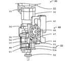
- FIG. 5 is a perspective view of an end effector 30 in an initial state.
- FIG. 6 is a perspective view of the end effector 30 in a posture change state. Explanatory drawing which shows an example of operation
- FIG. 1 is a schematic explanatory view of an articulated robot 20 which is an example of the present invention.
- FIG. 2 is a perspective view of the end effector 30 in an initial state.
- FIG. 3 is a perspective view of the end effector 30 in the attitude change state.
- FIG. 4 is an explanatory view showing an example of the operation of the end effector 30.
- the articulated robot 20 picks up the workpiece W, changes its posture, and carries out an operation of mounting it on the mounting member.
- the workpiece W is not particularly limited, and examples thereof include mechanical components, electrical components, electronic components, and chemical components.
- the workpiece W may be, for example, one in which connectors, pins, etc. are disposed in a predetermined direction, and positioned and positioned in a specific direction.
- a mounting member is a member which arranges and mounts the workpiece
- work W for example, a pallet, a tray, etc. are mentioned.
- the articulated robot 20 collects the workpieces W from the storage unit storing the one or more workpieces W, and moves and places the collected workpieces W on a pallet in a predetermined arrangement.
- the articulated robot 20 includes an arm 23, a base 24, a collecting unit 25, and a control unit (not shown).
- the arm unit 23 has a first arm 21 in which the collecting unit 25 is disposed on the distal end side, and a second arm 22 that supports the first arm 21 and is disposed on the base 24.
- the arm unit 23 is driven by a plurality of drive units.
- the collecting unit 25 is for mounting the end effector 30 for collecting the work W, and is rotatably mounted on the tip of the arm unit 23.
- a mounting portion 26 for mounting the end effector 30 is disposed on the lower surface side of the collecting portion 25.
- the control unit controls the entire device of the articulated robot 20, and includes a CPU and the like.
- the end effector 30 picks up the workpiece W, changes the posture of the workpiece, and mounts the workpiece W on a pallet or the like.
- the end effector 30 includes a mounting portion 31, a connection body 32, an external pipe 33, a connection port 34, and a support 36.
- the end effector 30 includes a pressure operation unit 40, a rack 44, a gear unit 45, a tool unit 50, a movable piping 51, a nozzle 52, a first stopper 53, and a second stopper 54. There is.
- the end effector 30 changes the attitude of the tool unit 50 using the pressure supplied from the articulated robot 20 to change the attitude of the workpiece W.
- the movement path of the tip of the tool unit 50 is a circular arc, and the tool unit 50 rotates in the range of 0 ° to 90 °, such as horizontal state from the vertical state.
- the end effector 30 is not provided with a drive source such as a control valve or a motor other than the piping. Since the articulated robot 20 handles a small work W such as an electronic component, it has, for example, a relatively light and compact arm unit 23.
- the end effector 30 is lightweight because no drive source is provided, and can be used for the articulated robot 20 provided with the lightweight and compact arm portion 23.
- the mounting unit 31 is mounted to the mounting unit 26 disposed at the tip of the arm unit 23 of the articulated robot 20.
- the connection body 32 is a cylindrical member in which the mounting portion 31 is disposed on the upper surface side and the support 36 is disposed on the lower surface side.
- An external pipe 33 is disposed in the connection body 32 and any one of negative pressure, positive pressure and normal pressure is supplied from the articulated robot 20.
- connection ports 34 are disposed on the four sides.
- the pressure operation unit 40 is connected to one of the connection ports 34, and the pressure is supplied from the articulated robot 20 to the pressure operation unit 40 via the connection port 34.
- the support 36 is a member fixed below the connection port 34, and supports the gear portion 45 and the tool portion 50.
- the support 36 is formed with a groove 37 through which the movable pipe 51 moves in accordance with the change of the posture of the tool 50.
- the pressure operation unit 40 is configured as an air cylinder operated by the pressure supplied from the articulated robot 20, and includes a piston 41 and a cylinder 42 as shown in FIG.
- one end of a rod fixed to the piston 41 is fixed to the rack 44.
- the second pipe 57 is disposed at one end, and the third pipe 58 is disposed at the other end.
- the positive pressure supplied through the connection port 34 causes the piston 41 to The inside of the cylinder 42 is reciprocated (up and down movement).
- the rack 44 is a member formed in an L-shape, and is connected to the pressure operation unit 40 to move in a predetermined direction (here, the direction in which the end effector 30 is formed, the vertical direction). The rack 44 reciprocates (moves up and down) as the piston 41 moves.
- the gear portion 45 is engaged with the rack 44 to change the posture of the tool portion 50, and the first pinion gear 46 engaged with the rack 44 and the second pinion gear 47 connected with the tool portion 50 and engaged with the first pinion gear 46. And. In the gear portion 45, along with the vertical movement of the rack 44, the first pinion gear 46 and the second pinion gear 47 axially rotate.
- the first pinion gear 46 has a larger diameter than the second pinion gear 47. At this time, the diameter ratio of the first pinion gear 46 to the second pinion gear 47 may be larger than one. Further, the gear ratio of the first pinion gear 46 to the second pinion gear 47 may be larger than one.
- the gear ratio of the first pinion gear 46 and the second pinion gear 47 may be n: 1 (n> 1), or more specifically, 2: 1.
- the rack 44 moves in the vertical direction
- the first pinion gear 46 and the second pinion gear 47 are axially supported by the support 36 so as to be in the vertical direction.
- the positioning rod 48 is fixed to the second pinion gear 47.
- the tip of the positioning rod 48 moves in a circular arc as the second pinion gear 47 rotates.
- the tool unit 50 is a member that extracts the workpiece W and changes the posture of the collected workpiece W in accordance with the rotational movement of the gear unit 45.
- the tool portion 50 includes a first member 50a fixed to the rotation shaft of the second pinion gear 47, and a second member 50b provided at the tip of the first member 50a.
- a nozzle 52 for collecting the workpiece W by pressure is detachably mounted on the lower surface side of the tool portion 50.
- the first member 50 a is a vertically long plate-like member pivotably supported on the side of the support 36.
- the second member 50 b is a plate-like member in which the horizontal direction (left and right direction) is the longitudinal direction when the nozzle 52 is in the vertical direction.
- the tool unit 50 changes the posture of the workpiece, but the change of the posture is not particularly limited, and may be in the range of 0 ° to 90 °.
- the posture of the workpiece W is changed by 90 degrees by rotating by 90 degrees (see FIGS. 3 and 4).
- One end of the movable pipe 51 is connected to the first pipe 56, and the other end is connected to the nozzle 52, and the supply direction can be changed by the rotation of the tool unit 50.
- the nozzle 52 is a member for collecting the workpiece W by the supplied negative pressure and releasing the workpiece W by releasing the negative pressure.
- the nozzle 52 is replaced according to the type of the work W.
- the end effector 30 also includes a first stopper 53 and a second stopper 54 fixed to the support 36.
- the first stopper 53 abuts on the positioning rod 48 to restrict the movement when the tool portion 50 is in the posture in the vertical direction. Further, the second stopper 54 abuts on the positioning rod 48 when the tool portion 50 is in the horizontal posture to restrict the movement.
- the posture of the tool unit 50 is fixed in the vertical direction and the horizontal direction by the positioning rod 48, the first stopper 53 and the second stopper 54. Ru.
- the control unit of the articulated robot 20 controls the arm unit 23 so as to move the end effector 30 to the accommodation unit accommodating the work W.
- the control unit controls the control valve of the articulated robot 20, supplies negative pressure to the nozzle 52 via the first pipe 56 and the movable pipe 51, and causes the end effector 30 to collect the work W (FIG. 4A) ).
- the control unit supplies positive pressure to the pressure operation unit 40 via the third pipe 58 to fix the tool unit 50.
- the control unit stops the positive pressure supply to the third pipe 58, and supplies the positive pressure to the pressure operation unit 40 via the second pipe 57. Then, with the movement of the piston 41, the rack 44 moves, and the first pinion gear 46 and the second pinion gear 47 rotate. The tool unit 50 rotates with the rotation of the second pinion gear 47, and the posture of the work W is changed (FIG. 4B). Then, the control unit controls the arm unit 23 so that the work W moves to a predetermined position of the mounting member, stops the supply of the negative pressure to the nozzle 52, and places the work W on the mounting member.
- the pressure operation unit 40 of this embodiment corresponds to a pressure operation unit
- the rack 44 corresponds to a rack
- the gear unit 45 corresponds to a gear unit
- the tool unit 50 corresponds to a tool unit
- the mounting unit 31 is a mounting unit It corresponds to
- the end effector 30 extracts the work W, the pressure operation unit 40 operated by pressure, the rack 44 connected to the pressure operation unit 40 and moving, the gear unit 45 meshing with the rack 44, and
- the tool unit 50 is provided with a tool unit 50 for changing the posture of the work W collected along with the rotational movement of the gear unit 45.
- the end effector 30 picks up a workpiece by the tool unit 50, and the rack 44 moves according to the operation of the pressure operation unit 40, the gear unit 45 rotates, and the tool unit 50 moves and collects the workpiece W. Change the attitude.
- the gear portion 45 has a first pinion gear 46 meshing with the rack 44 and a second pinion gear 47 connected with the tool portion 50 and meshing with the first pinion gear 46.
- the arrangement position of the rack 44, the moving distance of the rack 44, and the like can be made appropriate, and the posture change of the work W is hardly hindered.
- the gear portion 45 has the first pinion gear 46 having a diameter larger than that of the second pinion gear 47, the moving distance of the rack 44 can be shortened.
- the tool unit 50 can change the posture of the workpiece W by 90 ° because the member direction moves between the vertical direction and the horizontal direction. Furthermore, since the tool unit 50 has a nozzle for collecting the workpiece W by pressure, the posture of the workpiece W and the collection of the workpiece W can be performed by pressure. Furthermore, the end effector 30 includes a mounting portion 31 mounted to the tip of the arm of the articulated robot 20. The end effector 30 can change the posture of the work without requiring a drive source such as a motor, and thus is highly applicable to, for example, an articulated arm robot 20 having a weight limit at its tip.
- the gear portion 45 includes the first pinion gear 46 and the second pinion gear 47.
- the present invention is not particularly limited thereto, and one pinion gear may be provided, or three or more. It is also good.
- FIG. 5 is a schematic view showing an example of another end effector 30B.
- the end effector 30B includes a gear portion 45B having only one pinion gear. Also in the end effector 30B configured in this way, the same effect as the above-described end effector 30 can be obtained.
- the double pinion (FIG. 4) is more preferable than the single pinion (FIG. 5).
- the pressure operation unit 40 operates in the vertical direction (up and down direction), but is not particularly limited thereto, and may operate in the horizontal direction (left and right, front and back direction). Further, although the first pinion gear 46 and the second pinion gear 47 are axially supported in the vertical direction, the present invention is not particularly limited thereto, and may be axially supported in the horizontal direction (left and right, front and back direction) .
- the posture of the work W is changed by 90 °, but it is not particularly limited thereto, and the posture may be changed at any angle.
- the end effector 30 has been described as being mounted on the articulated robot 20 in the embodiment described above, the end effector 30 is not particularly limited as long as it is mounted on a device that changes the posture of the workpiece W.
- the gear portion may have a first pinion gear meshing with the rack, and a second pinion gear connected to the tool portion and meshing with the first pinion gear. Good.
- the arrangement position of the rack, the movement distance of the rack, and the like can be made appropriate and it is difficult to disturb the change in the posture of the work.
- the first pinion gear may have a larger diameter than the second pinion gear.
- the movement distance of the rack can be shortened.
- the gear ratio of the first pinion gear and the second pinion gear may be larger than one.
- the rack may move in the vertical direction, and the first pinion gear and the second pinion gear may be axially supported in the vertical direction.
- the tool unit may change the posture of the work by 90 °. At this time, the tool portion may move between the vertical direction and the horizontal direction.
- the tool portion may have a nozzle that picks up the workpiece by pressure.
- the posture of the workpiece and the sampling of the workpiece can be performed by pressure.
- the end effector of the present disclosure may be provided with a mounting portion mounted to the arm tip of the articulated robot. Since this end effector can change the posture of the work without requiring a drive source such as a motor, it is highly meaningful to apply to, for example, an articulated arm robot having a weight limit at its tip.
- the end effector of the present disclosure can be used in the technical field of an apparatus that performs processing such as collecting and arranging a work.
Landscapes
- Engineering & Computer Science (AREA)
- Robotics (AREA)
- Mechanical Engineering (AREA)
- Manipulator (AREA)
Abstract
エンドエフェクタは、ワークを採取するものであり、圧力により動作する圧力動作部と、圧力動作部に接続されて移動するラックと、ラックに噛合するギヤ部と、ワークを採取しギヤ部の回転運動に伴い採取したワークの姿勢を変更するツール部と、を備える。
Description
本明細書では、エンドエフェクタを開示する。
従来、エンドエフェクタとしては、例えば、部品供給部から半導体チップを取り出し上下方向に180度反転させるピックアップノズルを有するものが提案されている(例えば、特許文献1参照)。このエンドエフェクタでは、モータなどの駆動源により半導体チップを反転させる。
ところで、この特許文献1に記載されたエンドエフェクタでは、モータなどの駆動源を要するが、エンドエフェクタは装置の先端に装着されるものであるため、できるだけ簡素な構成とすることが望まれていた。
本開示は、このような課題に鑑みなされたものであり、できるだけ簡素な構成でワークの姿勢を変更することができるエンドエフェクタを提供することを主目的とする。
本明細書で開示するエンドエフェクタは、上述の主目的を達成するために以下の手段を採った。
本明細書で開示するエンドエフェクタは、
ワークを採取するエンドエフェクタであって、
圧力により動作する圧力動作部と、
前記圧力動作部に接続されて移動するラックと、
ラックに噛合するギヤ部と、
前記ワークを採取し前記ギヤ部の回転運動に伴い採取した該ワークの姿勢を変更するツール部と、
を備えたエンドエフェクタ。
ワークを採取するエンドエフェクタであって、
圧力により動作する圧力動作部と、
前記圧力動作部に接続されて移動するラックと、
ラックに噛合するギヤ部と、
前記ワークを採取し前記ギヤ部の回転運動に伴い採取した該ワークの姿勢を変更するツール部と、
を備えたエンドエフェクタ。
このエンドエフェクタは、ツール部によりワークを採取し、圧力動作部の動作に応じ、ラックが移動してギヤ部が回転運動し、ツール部が移動して採取したワークの姿勢を変更する。このエンドエフェクタでは、圧力で動作するためモータのような駆動源を要せず、ラックとギヤ部という簡素な構成でワークの姿勢を変更することができる。
本実施形態を図面を参照しながら以下に説明する。図1は、本発明の一例である多関節ロボット20の概略説明図である。図2は、エンドエフェクタ30の初期状態の斜視図である。図3は、エンドエフェクタ30の姿勢変更状態の斜視図である。図4は、エンドエフェクタ30の動作の一例を示す説明図である。多関節ロボット20は、ワークWを採取してその姿勢を変更し、載置部材に載置する作業を行うものである。ワークWは、特に限定されないが、例えば、機械部品、電気部品、電子部品、化学部品などが挙げられる。このワークWは、例えば、コネクタやピンなどが所定の方向に配設されているものなど、特定の方向に位置決めして載置するものが挙げられる。また、載置部材は、ワークWを整列して載置する部材であり、例えばパレットやトレイなどが挙げられる。
多関節ロボット20は、1以上のワークWを収容した収容部からワークWを採取し、採取したワークWを所定の配列でパレット上へ移動載置する処理を行う。この多関節ロボット20は、アーム部23と、基部24と、採取部25と、図示しない制御部とを備える。アーム部23は、採取部25が先端側に配設された第1アーム21と、第1アーム21を支持し基部24に配設された第2アーム22とを有している。アーム部23は、複数の駆動部によって駆動される。採取部25は、ワークWを採取するエンドエフェクタ30を装着するものであり、アーム部23の先端に回動可能に装着されている。採取部25の下面側には、エンドエフェクタ30を装着する装着部26が配設されている。制御部は、多関節ロボット20の装置全体を制御するものであり、CPUなどを備えている。
エンドエフェクタ30は、ワークWを採取し、このワークの姿勢を変更してパレットなどへ載置可能に構成されている。このエンドエフェクタ30は、図2~4に示すように、装着部31と、接続体32と、外部配管33と、接続ポート34と、支持体36とを備えている。また、エンドエフェクタ30は、圧力動作部40と、ラック44と、ギヤ部45と、ツール部50と、可動配管51と、ノズル52と、第1ストッパ53と、第2ストッパ54とを備えている。このエンドエフェクタ30は、多関節ロボット20から供給された圧力を用いて、ツール部50の姿勢を変更することによりワークWの姿勢を変更する。ツール部50は、先端の移動軌跡が円弧であり、鉛直状態から水平状態など0°~90°の範囲で回動する。このエンドエフェクタ30には、配管以外には、制御弁やモータなどの駆動源は設けられていない。多関節ロボット20は、電子部品などの小型のワークWを取り扱うことから、例えば、比較的軽量でコンパクトなアーム部23を備える。このエンドエフェクタ30は、駆動源が配設されていないため軽量であり、軽量でコンパクトなアーム部23を備える多関節ロボット20に用いることができる。
装着部31は、多関節ロボット20のアーム部23の先端に配設された装着部26に装着されるものである。接続体32は、上面側に装着部31が配設され、下面側に支持体36が配設された円柱状の部材である。接続体32には外部配管33が配設され、多関節ロボット20から、負圧、正圧及び常圧のいずれかが供給される。接続体32の下部には、その4面に接続ポート34が配設されている。このエンドエフェクタ30では、接続ポート34の一つに圧力動作部40が接続されており、この接続ポート34を介して圧力が多関節ロボット20から圧力動作部40へ供給される。支持体36は、接続ポート34の下方に固定された部材であり、ギヤ部45を軸支すると共にツール部50を軸支するものである。この支持体36には、ツール部50の姿勢変更に伴う可動配管51が移動する溝部37が形成されている。
圧力動作部40は、多関節ロボット20から供給された圧力により動作するエアシリンダとして構成されており、図4に示すように、ピストン41と、シリンダ42とを備える。この圧力動作部40では、ピストン41に固定されたロッドの一端がラック44に固定されている。この圧力動作部40には、一端側に第2配管57が配設され、他端側に第3配管58が配設されており、接続ポート34を介して供給された正圧によってピストン41がシリンダ42の内部を往復移動(上下動)する。ラック44は、L字状に形成された部材であり、圧力動作部40に接続されて所定方向(ここでは、エンドエフェクタ30の形成方向、上下方向)に移動する。このラック44は、ピストン41の移動に伴い、往復移動(上下動)する。
ギヤ部45は、ラック44に噛合しツール部50の姿勢を変更するものであり、ラック44に噛合する第1ピニオンギヤ46と、ツール部50が接続され第1ピニオンギヤ46と噛合する第2ピニオンギヤ47とを有している。このギヤ部45では、ラック44の上下動に伴い、第1ピニオンギヤ46及び第2ピニオンギヤ47が軸回転する。この第1ピニオンギヤ46は、第2ピニオンギヤ47より大きい直径を有する。このとき、第2ピニオンギヤ47に対する第1ピニオンギヤ46の直径比は、1より大きいものとしてもよい。また、第2ピニオンギヤ47に対する第1ピニオンギヤ46のギヤ比は1より大きいものとしてもよい。即ち、第1ピニオンギヤ46と第2ピニオンギヤ47とのギヤ比は、n:1(n>1)としてもよく、具体的には、2:1としてもよい。このエンドエフェクタ30では、エンドエフェクタ30を鉛直方向に固定した場合、ラック44は鉛直方向に移動し、第1ピニオンギヤ46と第2ピニオンギヤ47とは鉛直方向になるよう支持体36に軸支されている。第2ピニオンギヤ47には、位置決め棒48が固定されている。位置決め棒48は、第2ピニオンギヤ47の回転に伴いその先端が円弧を描いて移動する。
ツール部50は、ワークWを採取しギヤ部45の回転運動に伴い、採取したワークWの姿勢を変更する部材である。このツール部50は、第2ピニオンギヤ47の回転軸に固定された第1部材50aと、第1部材50aの先端に設けられた第2部材50bとを有している。このツール部50の下面側には、圧力によりワークWを採取するノズル52が取り外し可能に装着されている。第1部材50aは、支持体36の側方に回動可能に軸支された縦長の板状部材である。第2部材50bは、ノズル52が鉛直方向にあるときに水平方向(左右方向)が長手方向となる板状部材である。このツール部50は、ワークの姿勢を変更するが、その姿勢変更は、特に限定されず、0°以上90°以下の範囲としてもよい。このツール部50では、90°回動することにより、ワークWの姿勢を90°変更する(図3、4参照)。可動配管51は、一端が第1配管56に接続され、他端がノズル52に接続されており、ツール部50の回動により供給方向を変更可能な配管である。ノズル52は、供給された負圧によりワークWを採取すると共に、負圧を解除することによりワークWを離す部材である。このノズル52は、ワークWの種別に応じて取り替えられる。また、エンドエフェクタ30は、支持体36に固定された、第1ストッパ53と、第2ストッパ54とを備えている。第1ストッパ53は、ツール部50が鉛直方向の姿勢となるときに位置決め棒48に当接してこの移動を規制するものである。また、第2ストッパ54は、ツール部50が水平方向の姿勢となるときに位置決め棒48に当接してこの移動を規制するものである。このエンドエフェクタ30では、圧力動作部40に必要以上の圧力が供給された場合でも、位置決め棒48、第1ストッパ53及び第2ストッパ54によりツール部50の姿勢が鉛直方向及び水平方向に固定される。
次に、こうして構成された本実施形態の多関節ロボット20の動作、特に、ワークWを採取してその姿勢を変更して載置部材へ載置する動作を図4を用いて説明する。まず、多関節ロボット20の制御部は、ワークWを収容した収容部にエンドエフェクタ30を移動するようアーム部23を制御する。次に、制御部は、多関節ロボット20の制御弁を制御し、第1配管56及び可動配管51を介してノズル52に負圧を供給し、ワークWをエンドエフェクタ30に採取させる(図4A)。このとき、制御部は、第3配管58を介して正圧を圧力動作部40に供給し、ツール部50を固定させる。次に、制御部は、第3配管58への正圧供給を停止し、第2配管57を介して正圧を圧力動作部40に供給する。すると、ピストン41の移動に伴い、ラック44が移動し、第1ピニオンギヤ46及び第2ピニオンギヤ47が回転する。ツール部50は、第2ピニオンギヤ47の回転に伴って回動し、ワークWの姿勢が変更される(図4B)。そして、制御部は、ワークWが載置部材の所定位置へ移動するようアーム部23を制御し、ノズル52への負圧の供給を停止して載置部材上にワークWを載置させる。
ここで、本実施形態の構成要素と本発明の構成要素との対応関係を明らかにする。本実施形態の圧力動作部40が圧力動作部に相当し、ラック44がラックに相当し、ギヤ部45がギヤ部に相当し、ツール部50がツール部に相当し、装着部31が装着部に相当する。
以上説明した本実施形態のエンドエフェクタ30は、圧力により動作する圧力動作部40と、圧力動作部40に接続されて移動するラック44と、ラック44に噛合するギヤ部45と、ワークWを採取しギヤ部45の回転運動に伴い採取したワークWの姿勢を変更するツール部50とを備えている。このエンドエフェクタ30は、ツール部50によりワークを採取し、圧力動作部40の動作に応じ、ラック44が移動してギヤ部45が回転運動し、ツール部50が移動して採取したワークWの姿勢を変更する。このエンドエフェクタ30では、圧力で動作するためモータのような駆動源を要せず、ラック44とギヤ部45という簡素な構成でワークWの姿勢を変更することができる。また、このエンドエフェクタ30は、駆動源を備えないため、より軽量化を図ることができる。
また、ギヤ部45は、ラック44に噛合する第1ピニオンギヤ46と、ツール部50が接続され第1ピニオンギヤ46と噛合する第2ピニオンギヤ47とを有している。このエンドエフェクタ30では、第1及び第2ピニオンギヤ46,47を用いることによりラック44の配置位置やラック44の移動距離などを適正にすることができ、ワークWの姿勢変更を妨げにくい。更に、ギヤ部45は、第2ピニオンギヤ47より大きい直径を有する第1ピニオンギヤ46を有するため、ラック44の移動距離を短くすることができる。更にまた、エンドエフェクタ30は、ラック44が鉛直方向に移動し、第1ピニオンギヤ46と第2ピニオンギヤ47とが鉛直方向に軸支されているため、ラック44の移動や第1及び第2ピニオンギヤ46,47の配置において、ワークWの姿勢変更を妨げにくい。
また、ツール部50は、その部材方向が鉛直方向と水平方向との間で移動することから、ワークWの姿勢を90°変更することができる。更に、ツール部50は、圧力によりワークWを採取するノズルを有するため、ワークWの姿勢やワークWの採取を圧力により行うことができる。更にまた、エンドエフェクタ30は、多関節ロボット20のアーム先端に装着される装着部31を備える。このエンドエフェクタ30は、モータなどの駆動源を要さずにワークの姿勢を変更できるから、例えば、先端に重量制限などがある多関節アームロボット20に適用する意義が高い。
なお、本発明は上述した実施形態に何ら限定されることはなく、本発明の技術的範囲に属する限り種々の態様で実施し得ることはいうまでもない。
例えば、上述した実施形態では、ギヤ部45は、第1ピニオンギヤ46と第2ピニオンギヤ47とを備えるものとしたが、特にこれに限定されず、ピニオンギヤは1つとしてもよいし、3つ以上としてもよい。図5は、別のエンドエフェクタ30Bの一例を表す概略図である。このエンドエフェクタ30Bは、ピニオンギヤを1つだけ有するギヤ部45Bを備える。このように構成したエンドエフェクタ30Bにおいても、上述したエンドエフェクタ30と同様の効果を得ることができる。なお、ラック44の移動位置とツール部50の位置状態の関係やラック44の移動距離を考慮すると、シングルピニオン(図5)よりもダブルピニオン(図4)の方が好ましい。
上述した実施形態では、圧力動作部40は鉛直方向(上下方向)に動作するものとしたが、特にこれに限定されず、水平方向(左右、前後方向)に動作するものとしてもよい。また、第1ピニオンギヤ46と第2ピニオンギヤ47とは、鉛直方向に軸支されるものとしたが、特にこれに限定されず、水平方向(左右、前後方向)に軸支されるものとしてもよい。
上述した実施形態では、ワークWの姿勢を90°変更するものとしたが、特にこれに限定されず、任意の角度で姿勢を変更するものとしてもよい。
上述した実施形態では、エンドエフェクタ30は、多関節ロボット20に装着されるものとして説明したが、ワークWの姿勢を変更する装置に装着されるものとすれば特にこれに限定されない。
ここで、本開示のエンドエフェクタにおいて、前記ギヤ部は、前記ラックに噛合する第1ピニオンギヤと、前記ツール部が接続され前記第1ピニオンギヤと噛合する第2ピニオンギヤとを有しているものとしてもよい。このエンドエフェクタでは、第1及び第2ピニオンギヤを用いることによりラックの配置位置やラックの移動距離などを適正にすることができワークの姿勢変更を妨げにくい。
第1及び第2ピニオンギヤを備える本開示のエンドエフェクタにおいて、前記第1ピニオンギヤは、前記第2ピニオンギヤより大きい直径を有するものとしてもよい。このエンドエフェクタでは、ラックの移動距離を短くすることができる。このとき、第1ピニオンギヤと第2ピニオンギヤのギヤ比は、1より大きいものとしてもよい。
第1及び第2ピニオンギヤを備える本開示のエンドエフェクタにおいて、前記ラックは、鉛直方向に移動し、前記第1ピニオンギヤと前記第2ピニオンギヤとは鉛直方向に軸支されているものとしてもよい。このエンドエフェクタでは、ラックの移動や第1及び第2ピニオンギヤの配置において、ワークの姿勢変更を妨げにくい。
本開示のエンドエフェクタにおいて、前記ツール部は、前記ワークの姿勢を90°変更するものとしてもよい。このとき、ツール部はその部材方向が鉛直方向と水平方向との間で移動するものとしてもよい。
本開示のエンドエフェクタにおいて、前記ツール部は、圧力により前記ワークを採取するノズルを有するものとしてもよい。このエンドエフェクタでは、ワークの姿勢やワークの採取を圧力により行うことができる。
本開示のエンドエフェクタは、多関節ロボットのアーム先端に装着される装着部、を備えたものとしてもよい。このエンドエフェクタは、モータなどの駆動源を要さずにワークの姿勢を変更できるから、例えば、先端に重量制限などがある多関節アームロボットに適用する意義が高い。
本開示のエンドエフェクタは、ワークを採取、配置などの処理を行う装置の技術分野に利用可能である。
20 多関節ロボット、21 第1アーム、22 第2アーム、23 アーム部、24 基部、25 採取部、26 装着部、30,30B エンドエフェクタ、31 装着部、32 接続体、33 外部配管、34 接続ポート、36 支持体、37 溝部、40 圧力動作部、41 ピストン、42 シリンダ、44 ラック、45,45B ギヤ部、46 第1ピニオンギヤ、47 第2ピニオンギヤ、48 位置決め棒、50 ツール部、50a 第1部材、50b 第2部材、51 可動配管、52 ノズル、53 第1ストッパ、54 第2ストッパ、56 第1配管、57 第2配管、58 第3配管、W ワーク。
Claims (7)
- ワークを採取するエンドエフェクタであって、
圧力により動作する圧力動作部と、
前記圧力動作部に接続されて移動するラックと、
ラックに噛合するギヤ部と、
前記ワークを採取し前記ギヤ部の回転運動に伴い採取した該ワークの姿勢を変更するツール部と、
を備えたエンドエフェクタ。 - 前記ギヤ部は、前記ラックに噛合する第1ピニオンギヤと、前記ツール部が接続され前記第1ピニオンギヤと噛合する第2ピニオンギヤとを有している、請求項1に記載のエンドエフェクタ。
- 前記第1ピニオンギヤは、前記第2ピニオンギヤより大きい直径を有する、請求項2に記載のエンドエフェクタ。
- 前記ラックは、鉛直方向に移動し、前記第1ピニオンギヤと前記第2ピニオンギヤとは鉛直方向に軸支されている、請求項2又は3に記載のエンドエフェクタ。
- 前記ツール部は、前記ワークの姿勢を90°変更する、請求項1~4のいずれか1項に記載のエンドエフェクタ。
- 前記ツール部は、圧力により前記ワークを採取するノズルを有する、請求項1~5のいずれか1項に記載のエンドエフェクタ。
- 請求項1~6のいずれか1項に記載のエンドエフェクタであって、
多関節ロボットのアーム先端に装着される装着部、を備えたエンドエフェクタ。
Priority Applications (2)
| Application Number | Priority Date | Filing Date | Title |
|---|---|---|---|
| JP2019530309A JP6910442B2 (ja) | 2017-07-20 | 2017-07-20 | エンドエフェクタ |
| PCT/JP2017/026289 WO2019016919A1 (ja) | 2017-07-20 | 2017-07-20 | エンドエフェクタ |
Applications Claiming Priority (1)
| Application Number | Priority Date | Filing Date | Title |
|---|---|---|---|
| PCT/JP2017/026289 WO2019016919A1 (ja) | 2017-07-20 | 2017-07-20 | エンドエフェクタ |
Publications (1)
| Publication Number | Publication Date |
|---|---|
| WO2019016919A1 true WO2019016919A1 (ja) | 2019-01-24 |
Family
ID=65016634
Family Applications (1)
| Application Number | Title | Priority Date | Filing Date |
|---|---|---|---|
| PCT/JP2017/026289 Ceased WO2019016919A1 (ja) | 2017-07-20 | 2017-07-20 | エンドエフェクタ |
Country Status (2)
| Country | Link |
|---|---|
| JP (1) | JP6910442B2 (ja) |
| WO (1) | WO2019016919A1 (ja) |
Families Citing this family (1)
| Publication number | Priority date | Publication date | Assignee | Title |
|---|---|---|---|---|
| KR20230152349A (ko) * | 2022-04-27 | 2023-11-03 | 주식회사 씨젠 | 연결 구조체 |
Citations (6)
| Publication number | Priority date | Publication date | Assignee | Title |
|---|---|---|---|---|
| JPS5032931Y1 (ja) * | 1970-10-15 | 1975-09-25 | ||
| US4820113A (en) * | 1987-08-03 | 1989-04-11 | Alliance Automation Systems, Inc. | Head for attachment to a robot to pick up articles |
| JPH06270088A (ja) * | 1993-03-19 | 1994-09-27 | Harmo Soken:Kk | 移載装置 |
| JPH071042A (ja) * | 1993-06-15 | 1995-01-06 | Komatsu Ltd | プレスブレーキ用ロボット装置 |
| JPH07116984A (ja) * | 1993-08-30 | 1995-05-09 | Sanyo Electric Co Ltd | ロボットハンド及びそれを使用した部品供給装置 |
| JP2016026117A (ja) * | 2011-02-11 | 2016-02-12 | ザ プロクター アンド ギャンブルカンパニー | 移動装置のためのつかみ機構アセンブリ |
Family Cites Families (5)
| Publication number | Priority date | Publication date | Assignee | Title |
|---|---|---|---|---|
| JPS62176727A (ja) * | 1986-01-30 | 1987-08-03 | Matsuura Tekkosho:Kk | ワ−ク受け渡し装置 |
| JPH02106245A (ja) * | 1988-10-11 | 1990-04-18 | Matsuura Tekkosho:Kk | ワーク受け渡し装置 |
| JPH0520844U (ja) * | 1991-05-21 | 1993-03-19 | 株式会社オオガ | ワーク受渡装置 |
| JPH06155219A (ja) * | 1992-11-20 | 1994-06-03 | Miyano:Kk | ワーク交換装置を備えた工作機械 |
| JP2001313498A (ja) * | 2000-04-27 | 2001-11-09 | Sony Corp | 電子部品の実装装置 |
-
2017
- 2017-07-20 WO PCT/JP2017/026289 patent/WO2019016919A1/ja not_active Ceased
- 2017-07-20 JP JP2019530309A patent/JP6910442B2/ja active Active
Patent Citations (6)
| Publication number | Priority date | Publication date | Assignee | Title |
|---|---|---|---|---|
| JPS5032931Y1 (ja) * | 1970-10-15 | 1975-09-25 | ||
| US4820113A (en) * | 1987-08-03 | 1989-04-11 | Alliance Automation Systems, Inc. | Head for attachment to a robot to pick up articles |
| JPH06270088A (ja) * | 1993-03-19 | 1994-09-27 | Harmo Soken:Kk | 移載装置 |
| JPH071042A (ja) * | 1993-06-15 | 1995-01-06 | Komatsu Ltd | プレスブレーキ用ロボット装置 |
| JPH07116984A (ja) * | 1993-08-30 | 1995-05-09 | Sanyo Electric Co Ltd | ロボットハンド及びそれを使用した部品供給装置 |
| JP2016026117A (ja) * | 2011-02-11 | 2016-02-12 | ザ プロクター アンド ギャンブルカンパニー | 移動装置のためのつかみ機構アセンブリ |
Also Published As
| Publication number | Publication date |
|---|---|
| JP6910442B2 (ja) | 2021-07-28 |
| JPWO2019016919A1 (ja) | 2019-12-26 |
Similar Documents
| Publication | Publication Date | Title |
|---|---|---|
| TWI491483B (zh) | 機械手及使用該機械手的生產設備 | |
| JP5272647B2 (ja) | ロボット | |
| JP2016127187A (ja) | チップ部品実装方法及び実装装置 | |
| CN204416558U (zh) | 移料装置 | |
| CN104858586A (zh) | 数控焊接机 | |
| US11389952B2 (en) | Robot arm | |
| CN103495971A (zh) | 一种五自由度组合式机器人平台 | |
| CN107053252A (zh) | 机器人 | |
| WO2017159426A1 (ja) | 作業ユニット及び作業装置 | |
| JP2023090918A (ja) | 多関節ロボット | |
| TW201617192A (zh) | 機器人及機器人系統 | |
| JPWO2016129526A1 (ja) | エンドエフェクタ及びロボット | |
| WO2019011289A1 (zh) | 机械手的底照视觉系统及其工作方法 | |
| JP6586162B2 (ja) | アームロボット | |
| JP6910442B2 (ja) | エンドエフェクタ | |
| CN109311152B (zh) | 输送装置 | |
| WO2019007427A1 (zh) | 可视觉的机械手结构 | |
| CN205402122U (zh) | X/y轴方向的精密位移平台 | |
| CN110944809B (zh) | 末端执行器 | |
| JP6825136B2 (ja) | エンドエフェクタ,多関節ロボット及び作業実行装置 | |
| JP2021109253A (ja) | 作業アーム | |
| CN216967784U (zh) | 一种用于杯壶生产线的三轴机械臂 | |
| JP2010028032A (ja) | 電子部品実装装置 | |
| CN212913373U (zh) | 一种姿态调整机构、主操作手装置及手术机器人 | |
| JP2005066723A (ja) | 4自由度パラレルロボット |
Legal Events
| Date | Code | Title | Description |
|---|---|---|---|
| 121 | Ep: the epo has been informed by wipo that ep was designated in this application |
Ref document number: 17918185 Country of ref document: EP Kind code of ref document: A1 |
|
| ENP | Entry into the national phase |
Ref document number: 2019530309 Country of ref document: JP Kind code of ref document: A |
|
| NENP | Non-entry into the national phase |
Ref country code: DE |
|
| 122 | Ep: pct application non-entry in european phase |
Ref document number: 17918185 Country of ref document: EP Kind code of ref document: A1 |