WO2019016845A1 - Dispositif d'alimentation en eau chaude - Google Patents
Dispositif d'alimentation en eau chaude Download PDFInfo
- Publication number
- WO2019016845A1 WO2019016845A1 PCT/JP2017/025839 JP2017025839W WO2019016845A1 WO 2019016845 A1 WO2019016845 A1 WO 2019016845A1 JP 2017025839 W JP2017025839 W JP 2017025839W WO 2019016845 A1 WO2019016845 A1 WO 2019016845A1
- Authority
- WO
- WIPO (PCT)
- Prior art keywords
- hot water
- heat medium
- storage tank
- water storage
- pump
- Prior art date
Links
- XLYOFNOQVPJJNP-UHFFFAOYSA-N water Substances O XLYOFNOQVPJJNP-UHFFFAOYSA-N 0.000 title claims description 339
- 238000009835 boiling Methods 0.000 claims description 183
- 238000010438 heat treatment Methods 0.000 claims description 49
- 239000003507 refrigerant Substances 0.000 claims description 38
- 230000007246 mechanism Effects 0.000 claims description 18
- 238000011144 upstream manufacturing Methods 0.000 claims description 4
- 101100328518 Caenorhabditis elegans cnt-1 gene Proteins 0.000 description 49
- 238000010586 diagram Methods 0.000 description 16
- 230000006870 function Effects 0.000 description 16
- 238000013517 stratification Methods 0.000 description 15
- 101150044602 Slc28a2 gene Proteins 0.000 description 11
- VREFGVBLTWBCJP-UHFFFAOYSA-N alprazolam Chemical compound C12=CC(Cl)=CC=C2N2C(C)=NN=C2CN=C1C1=CC=CC=C1 VREFGVBLTWBCJP-UHFFFAOYSA-N 0.000 description 9
- 230000004048 modification Effects 0.000 description 6
- 238000012986 modification Methods 0.000 description 6
- 238000001514 detection method Methods 0.000 description 5
- 238000004781 supercooling Methods 0.000 description 5
- 230000000694 effects Effects 0.000 description 4
- 230000005494 condensation Effects 0.000 description 3
- 238000009833 condensation Methods 0.000 description 3
- 230000003247 decreasing effect Effects 0.000 description 3
- 239000007788 liquid Substances 0.000 description 3
- 238000000034 method Methods 0.000 description 3
- 230000008569 process Effects 0.000 description 3
- CURLTUGMZLYLDI-UHFFFAOYSA-N Carbon dioxide Chemical compound O=C=O CURLTUGMZLYLDI-UHFFFAOYSA-N 0.000 description 2
- 230000009471 action Effects 0.000 description 2
- 230000000630 rising effect Effects 0.000 description 2
- 239000008399 tap water Substances 0.000 description 2
- 235000020679 tap water Nutrition 0.000 description 2
- 238000013459 approach Methods 0.000 description 1
- 239000012267 brine Substances 0.000 description 1
- 229910002092 carbon dioxide Inorganic materials 0.000 description 1
- 239000001569 carbon dioxide Substances 0.000 description 1
- 230000008859 change Effects 0.000 description 1
- 239000002131 composite material Substances 0.000 description 1
- 230000007423 decrease Effects 0.000 description 1
- 238000012545 processing Methods 0.000 description 1
- 230000005855 radiation Effects 0.000 description 1
- 238000010079 rubber tapping Methods 0.000 description 1
- 239000004065 semiconductor Substances 0.000 description 1
- HPALAKNZSZLMCH-UHFFFAOYSA-M sodium;chloride;hydrate Chemical compound O.[Na+].[Cl-] HPALAKNZSZLMCH-UHFFFAOYSA-M 0.000 description 1
- 238000012546 transfer Methods 0.000 description 1
Images


Classifications
-
- F—MECHANICAL ENGINEERING; LIGHTING; HEATING; WEAPONS; BLASTING
- F24—HEATING; RANGES; VENTILATING
- F24D—DOMESTIC- OR SPACE-HEATING SYSTEMS, e.g. CENTRAL HEATING SYSTEMS; DOMESTIC HOT-WATER SUPPLY SYSTEMS; ELEMENTS OR COMPONENTS THEREFOR
- F24D3/00—Hot-water central heating systems
- F24D3/08—Hot-water central heating systems in combination with systems for domestic hot-water supply
- F24D3/082—Hot water storage tanks specially adapted therefor
-
- F—MECHANICAL ENGINEERING; LIGHTING; HEATING; WEAPONS; BLASTING
- F24—HEATING; RANGES; VENTILATING
- F24D—DOMESTIC- OR SPACE-HEATING SYSTEMS, e.g. CENTRAL HEATING SYSTEMS; DOMESTIC HOT-WATER SUPPLY SYSTEMS; ELEMENTS OR COMPONENTS THEREFOR
- F24D19/00—Details
- F24D19/10—Arrangement or mounting of control or safety devices
- F24D19/1006—Arrangement or mounting of control or safety devices for water heating systems
- F24D19/1009—Arrangement or mounting of control or safety devices for water heating systems for central heating
- F24D19/1012—Arrangement or mounting of control or safety devices for water heating systems for central heating by regulating the speed of a pump
-
- F—MECHANICAL ENGINEERING; LIGHTING; HEATING; WEAPONS; BLASTING
- F24—HEATING; RANGES; VENTILATING
- F24D—DOMESTIC- OR SPACE-HEATING SYSTEMS, e.g. CENTRAL HEATING SYSTEMS; DOMESTIC HOT-WATER SUPPLY SYSTEMS; ELEMENTS OR COMPONENTS THEREFOR
- F24D19/00—Details
- F24D19/10—Arrangement or mounting of control or safety devices
- F24D19/1006—Arrangement or mounting of control or safety devices for water heating systems
- F24D19/1066—Arrangement or mounting of control or safety devices for water heating systems for the combination of central heating and domestic hot water
- F24D19/1072—Arrangement or mounting of control or safety devices for water heating systems for the combination of central heating and domestic hot water the system uses a heat pump
-
- F—MECHANICAL ENGINEERING; LIGHTING; HEATING; WEAPONS; BLASTING
- F24—HEATING; RANGES; VENTILATING
- F24D—DOMESTIC- OR SPACE-HEATING SYSTEMS, e.g. CENTRAL HEATING SYSTEMS; DOMESTIC HOT-WATER SUPPLY SYSTEMS; ELEMENTS OR COMPONENTS THEREFOR
- F24D3/00—Hot-water central heating systems
- F24D3/18—Hot-water central heating systems using heat pumps
-
- F—MECHANICAL ENGINEERING; LIGHTING; HEATING; WEAPONS; BLASTING
- F24—HEATING; RANGES; VENTILATING
- F24H—FLUID HEATERS, e.g. WATER OR AIR HEATERS, HAVING HEAT-GENERATING MEANS, e.g. HEAT PUMPS, IN GENERAL
- F24H15/00—Control of fluid heaters
- F24H15/20—Control of fluid heaters characterised by control inputs
- F24H15/212—Temperature of the water
- F24H15/223—Temperature of the water in the water storage tank
- F24H15/225—Temperature of the water in the water storage tank at different heights of the tank
-
- F—MECHANICAL ENGINEERING; LIGHTING; HEATING; WEAPONS; BLASTING
- F24—HEATING; RANGES; VENTILATING
- F24H—FLUID HEATERS, e.g. WATER OR AIR HEATERS, HAVING HEAT-GENERATING MEANS, e.g. HEAT PUMPS, IN GENERAL
- F24H15/00—Control of fluid heaters
- F24H15/30—Control of fluid heaters characterised by control outputs; characterised by the components to be controlled
- F24H15/335—Control of pumps, e.g. on-off control
- F24H15/34—Control of the speed of pumps
-
- F—MECHANICAL ENGINEERING; LIGHTING; HEATING; WEAPONS; BLASTING
- F24—HEATING; RANGES; VENTILATING
- F24H—FLUID HEATERS, e.g. WATER OR AIR HEATERS, HAVING HEAT-GENERATING MEANS, e.g. HEAT PUMPS, IN GENERAL
- F24H15/00—Control of fluid heaters
- F24H15/30—Control of fluid heaters characterised by control outputs; characterised by the components to be controlled
- F24H15/375—Control of heat pumps
- F24H15/38—Control of compressors of heat pumps
-
- F—MECHANICAL ENGINEERING; LIGHTING; HEATING; WEAPONS; BLASTING
- F24—HEATING; RANGES; VENTILATING
- F24H—FLUID HEATERS, e.g. WATER OR AIR HEATERS, HAVING HEAT-GENERATING MEANS, e.g. HEAT PUMPS, IN GENERAL
- F24H15/00—Control of fluid heaters
- F24H15/30—Control of fluid heaters characterised by control outputs; characterised by the components to be controlled
- F24H15/375—Control of heat pumps
- F24H15/385—Control of expansion valves of heat pumps
-
- F—MECHANICAL ENGINEERING; LIGHTING; HEATING; WEAPONS; BLASTING
- F24—HEATING; RANGES; VENTILATING
- F24H—FLUID HEATERS, e.g. WATER OR AIR HEATERS, HAVING HEAT-GENERATING MEANS, e.g. HEAT PUMPS, IN GENERAL
- F24H4/00—Fluid heaters characterised by the use of heat pumps
- F24H4/02—Water heaters
- F24H4/04—Storage heaters
-
- F—MECHANICAL ENGINEERING; LIGHTING; HEATING; WEAPONS; BLASTING
- F24—HEATING; RANGES; VENTILATING
- F24D—DOMESTIC- OR SPACE-HEATING SYSTEMS, e.g. CENTRAL HEATING SYSTEMS; DOMESTIC HOT-WATER SUPPLY SYSTEMS; ELEMENTS OR COMPONENTS THEREFOR
- F24D2200/00—Heat sources or energy sources
- F24D2200/12—Heat pump
- F24D2200/123—Compression type heat pumps
-
- F—MECHANICAL ENGINEERING; LIGHTING; HEATING; WEAPONS; BLASTING
- F24—HEATING; RANGES; VENTILATING
- F24D—DOMESTIC- OR SPACE-HEATING SYSTEMS, e.g. CENTRAL HEATING SYSTEMS; DOMESTIC HOT-WATER SUPPLY SYSTEMS; ELEMENTS OR COMPONENTS THEREFOR
- F24D2220/00—Components of central heating installations excluding heat sources
- F24D2220/08—Storage tanks
-
- F—MECHANICAL ENGINEERING; LIGHTING; HEATING; WEAPONS; BLASTING
- F24—HEATING; RANGES; VENTILATING
- F24D—DOMESTIC- OR SPACE-HEATING SYSTEMS, e.g. CENTRAL HEATING SYSTEMS; DOMESTIC HOT-WATER SUPPLY SYSTEMS; ELEMENTS OR COMPONENTS THEREFOR
- F24D2240/00—Characterizing positions, e.g. of sensors, inlets, outlets
- F24D2240/26—Vertically distributed at fixed positions, e.g. multiple sensors distributed over the height of a tank, or a vertical inlet distribution pipe having a plurality of orifices
-
- F—MECHANICAL ENGINEERING; LIGHTING; HEATING; WEAPONS; BLASTING
- F24—HEATING; RANGES; VENTILATING
- F24H—FLUID HEATERS, e.g. WATER OR AIR HEATERS, HAVING HEAT-GENERATING MEANS, e.g. HEAT PUMPS, IN GENERAL
- F24H15/00—Control of fluid heaters
- F24H15/20—Control of fluid heaters characterised by control inputs
- F24H15/227—Temperature of the refrigerant in heat pump cycles
- F24H15/232—Temperature of the refrigerant in heat pump cycles at the condenser
-
- F—MECHANICAL ENGINEERING; LIGHTING; HEATING; WEAPONS; BLASTING
- F24—HEATING; RANGES; VENTILATING
- F24H—FLUID HEATERS, e.g. WATER OR AIR HEATERS, HAVING HEAT-GENERATING MEANS, e.g. HEAT PUMPS, IN GENERAL
- F24H15/00—Control of fluid heaters
- F24H15/20—Control of fluid heaters characterised by control inputs
- F24H15/242—Pressure
-
- F—MECHANICAL ENGINEERING; LIGHTING; HEATING; WEAPONS; BLASTING
- F24—HEATING; RANGES; VENTILATING
- F24H—FLUID HEATERS, e.g. WATER OR AIR HEATERS, HAVING HEAT-GENERATING MEANS, e.g. HEAT PUMPS, IN GENERAL
- F24H15/00—Control of fluid heaters
- F24H15/30—Control of fluid heaters characterised by control outputs; characterised by the components to be controlled
- F24H15/305—Control of valves
- F24H15/32—Control of valves of switching valves
-
- F—MECHANICAL ENGINEERING; LIGHTING; HEATING; WEAPONS; BLASTING
- F24—HEATING; RANGES; VENTILATING
- F24H—FLUID HEATERS, e.g. WATER OR AIR HEATERS, HAVING HEAT-GENERATING MEANS, e.g. HEAT PUMPS, IN GENERAL
- F24H15/00—Control of fluid heaters
- F24H15/30—Control of fluid heaters characterised by control outputs; characterised by the components to be controlled
- F24H15/345—Control of fans, e.g. on-off control
-
- F—MECHANICAL ENGINEERING; LIGHTING; HEATING; WEAPONS; BLASTING
- F24—HEATING; RANGES; VENTILATING
- F24H—FLUID HEATERS, e.g. WATER OR AIR HEATERS, HAVING HEAT-GENERATING MEANS, e.g. HEAT PUMPS, IN GENERAL
- F24H15/00—Control of fluid heaters
- F24H15/40—Control of fluid heaters characterised by the type of controllers
- F24H15/414—Control of fluid heaters characterised by the type of controllers using electronic processing, e.g. computer-based
- F24H15/421—Control of fluid heaters characterised by the type of controllers using electronic processing, e.g. computer-based using pre-stored data
-
- F—MECHANICAL ENGINEERING; LIGHTING; HEATING; WEAPONS; BLASTING
- F24—HEATING; RANGES; VENTILATING
- F24H—FLUID HEATERS, e.g. WATER OR AIR HEATERS, HAVING HEAT-GENERATING MEANS, e.g. HEAT PUMPS, IN GENERAL
- F24H15/00—Control of fluid heaters
- F24H15/40—Control of fluid heaters characterised by the type of controllers
- F24H15/414—Control of fluid heaters characterised by the type of controllers using electronic processing, e.g. computer-based
- F24H15/45—Control of fluid heaters characterised by the type of controllers using electronic processing, e.g. computer-based remotely accessible
-
- Y—GENERAL TAGGING OF NEW TECHNOLOGICAL DEVELOPMENTS; GENERAL TAGGING OF CROSS-SECTIONAL TECHNOLOGIES SPANNING OVER SEVERAL SECTIONS OF THE IPC; TECHNICAL SUBJECTS COVERED BY FORMER USPC CROSS-REFERENCE ART COLLECTIONS [XRACs] AND DIGESTS
- Y02—TECHNOLOGIES OR APPLICATIONS FOR MITIGATION OR ADAPTATION AGAINST CLIMATE CHANGE
- Y02B—CLIMATE CHANGE MITIGATION TECHNOLOGIES RELATED TO BUILDINGS, e.g. HOUSING, HOUSE APPLIANCES OR RELATED END-USER APPLICATIONS
- Y02B30/00—Energy efficient heating, ventilation or air conditioning [HVAC]
- Y02B30/12—Hot water central heating systems using heat pumps
-
- Y—GENERAL TAGGING OF NEW TECHNOLOGICAL DEVELOPMENTS; GENERAL TAGGING OF CROSS-SECTIONAL TECHNOLOGIES SPANNING OVER SEVERAL SECTIONS OF THE IPC; TECHNICAL SUBJECTS COVERED BY FORMER USPC CROSS-REFERENCE ART COLLECTIONS [XRACs] AND DIGESTS
- Y02—TECHNOLOGIES OR APPLICATIONS FOR MITIGATION OR ADAPTATION AGAINST CLIMATE CHANGE
- Y02B—CLIMATE CHANGE MITIGATION TECHNOLOGIES RELATED TO BUILDINGS, e.g. HOUSING, HOUSE APPLIANCES OR RELATED END-USER APPLICATIONS
- Y02B30/00—Energy efficient heating, ventilation or air conditioning [HVAC]
- Y02B30/70—Efficient control or regulation technologies, e.g. for control of refrigerant flow, motor or heating
Definitions
- the present invention relates to a hot water supply apparatus, and more particularly to a hot water supply apparatus provided with a pump for transferring a heat medium to a hot water storage tank.
- a conventional hot water supply apparatus includes a hot water storage tank for storing a heat medium, a pump for conveying the heat medium to the hot water storage tank, and a thermistor for detecting the temperature of the hot water storage tank (for example, Reference 1).
- the first temperature distribution of the heat medium in the hot water storage tank when the temperature of the heat medium in the hot water storage tank is lowered due to the heat release of the hot water storage tank is the temperature of the heat medium in the hot water storage tank Is different from the second temperature distribution of the heat medium in the hot water storage tank when
- the control apparatus of the hot-water supply device of patent document 1 discriminate
- control apparatus of the hot-water supply apparatus of patent document 1 is changing the flow volume of the pump when performing boiling-up operation according to the discrimination
- the water heater of patent document 1 is improving the efficiency at the time of boiling the heat medium in a hot water storage tank.
- the control device of the water heating apparatus of Patent Document 1 determines the temperature distribution of the heat medium of the hot water storage tank based on the time change of the detected temperature of the thermistor.
- the thermistor of the hot water storage tank of the water heater of patent document 1 is one. For this reason, there is a possibility that the determination result is deviated from the actual temperature distribution. That is, the water heater of Patent Document 1 has a problem that it is difficult to ensure the determination accuracy of the temperature distribution of the heat medium in the hot water storage tank.
- the present invention has been made to solve the problems as described above, and it is an object of the present invention to provide a hot water supply device capable of determining the temperature distribution of the heat medium in the hot water storage tank with higher accuracy.
- a hot water supply apparatus comprises a hot water storage tank for storing a heat medium, a heating heat exchanger for heating the heat medium supplied to the hot water storage tank, a first pump for transporting the heat medium to the hot water storage tank, A heat medium circuit provided with a tank, a first pump, and a heat exchanger for heating, a lower temperature sensor provided in a hot water storage tank and detecting a lower temperature of the heat medium stored in the hot water storage tank Control provided with an upper temperature sensor provided in the tank, provided above the lower temperature sensor and detecting the upper temperature of the heat medium stored in the hot water storage tank, and a control device for controlling the first pump When the upper temperature is lower than the first boiling temperature, the apparatus performs a first boiling operation in which the first pump is operated at the first pump speed, and the upper temperature is the first boiling. Lower than the second boiling temperature higher than the upper temperature And, if the lower temperature is lower than a third boiling temperature lower than the first boiling temperature, the first pump is operated at a second pump rotational speed lower than the first
- the temperature distribution of the heat medium in the hot water storage tank can be determined with higher accuracy.
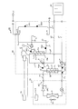
- FIG. 1 is a schematic configuration diagram of a hot water supply apparatus 100 according to Embodiment 1.
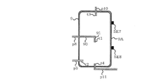
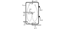
- FIG. 2 is a configuration explanatory view of a hot water storage tank 9 of the hot water supply apparatus 100 according to Embodiment 1.
- FIG. 2 is a block diagram of a control function of hot water supply device 100 according to the first embodiment.
- FIG. 6 is an operation explanatory view of first and second boiling operations of water heating apparatus 100 according to the first embodiment.
- 5 is a control flowchart of the hot water supply apparatus 100 according to the first embodiment. It is explanatory drawing of the temperature of the hot water storage tank 9 at the time of the start of 1st boiling operation, and the temperature of the hot water storage tank 9 at the time of start of 2nd boiling operation.
- FIG. 6 is a schematic configuration diagram of a modification of hot water supply device 100 according to Embodiment 1. It is a block diagram of a control function of a modification of hot water supply apparatus 100 concerning Embodiment 1.
- FIG. 8 is a schematic configuration diagram of a hot water supply apparatus 200 according to Embodiment 2.
- FIG. 13 is a block diagram of a control function of water heating apparatus 200 according to Embodiment 2.
- FIG. 14 is an operation explanatory view of a first boiling operation of the hot water supply apparatus 200 according to Embodiment 2.
- FIG. 16 is an operation explanatory view of a second boiling operation of the hot water supply apparatus 200 according to Embodiment 2.
- FIG. 10 is a schematic configuration diagram of a hot water supply apparatus 300 according to Embodiment 3.
- FIG. 18 is an explanatory diagram of a hot water storage tank 9 and an inflow piping p8c of the hot water supply apparatus 300 according to Embodiment 3. It is an enlarged view of the inflow piping p8c shown in FIG.
- the opening-and-closing mechanism part 12 in the 1st boiling operation is shown.
- the opening / closing mechanism part 12 in the 2nd boiling operation is shown.
- Embodiment 1 Hereinafter, Embodiment 1 will be described with reference to the drawings.
- size of each structural member may differ from an actual thing.
- the form of the component shown in the full text of the specification is just an example, and is not limited to these descriptions.
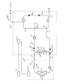
- FIG. 1 is a schematic block diagram of a hot water supply apparatus 100 according to the first embodiment.
- the water heating apparatus 100 includes a heat pump unit 20, a tank unit 30, and a remote controller 70 that outputs a control command to the tank unit 30.
- the heat pump unit 20 and the tank unit 30 are connected via the gas pipe P1 and the liquid pipe P2.
- the tank unit 30 is connected to the heating device 40 via the pipe p1 and the pipe p5.
- An example of the heating device 40 is a floor heating device and a radiator of an indoor unit of an air conditioner.
- the heat pump unit 20 includes a compressor 1 that compresses a refrigerant, a throttling device 3 that decompresses the refrigerant, a heat exchanger 4 that functions as an evaporator, and a blower 4A that supplies air to the heat exchanger 4 .
- the heat pump unit 20 also includes a pressure sensor SE1 that detects the pressure of the refrigerant discharged from the compressor 1, and a control device Cnt2 that controls the compressor 1, the expansion device 3, and the blower 4A.
- the compressor 1 and the first pump 8 and the second pump 5 described later each include an inverter.
- the throttling device 3 is an expansion valve.
- the tank unit 30 includes a heat medium circuit C including a primary circuit C1 and a secondary circuit C2 that receives heat from the primary circuit C1.
- the heat medium of the primary circuit C1 is water or brine.
- the heat medium of the secondary circuit C2 is water.
- the heat medium of the primary circuit C1 corresponds to the first heat medium, and the heat medium of the secondary circuit C2 corresponds to the second heat medium.
- the tank unit 30 further includes a hot water storage tank 9 for storing a heat medium, and a first pump 8 for transporting the heat medium to the hot water storage tank 9.
- the tank unit 30 includes a heating heat exchanger Hx that supplies the heat of the refrigerant generated by the heat pump unit 20 to the heat medium of the hot water storage tank 9.
- the heating heat exchanger Hx includes a first heat exchanger 2 and a second heat exchanger 7.
- the tank unit 30 includes a first heat exchanger 2 which exchanges heat between the refrigerant and the heat medium, and a second pump 5 which conveys the heat medium to the first heat exchanger 2.
- the first heat exchanger 2 includes a first heat medium flow path 2A for flowing a heat medium, and a refrigerant flow path 2B for flowing a refrigerant.
- the water heating apparatus 100 includes a refrigerant circuit RC provided with a compressor 1, a first heat exchanger 2, a throttling device 3 and a heat exchanger 4.
- a carbon dioxide refrigerant, an HFC refrigerant, an HC refrigerant, or an HFO refrigerant can be employed.
- the tank unit 30 has a flow path switching device 6 that switches the flow path of the heat medium of the primary circuit C1, and a second heat exchanger that exchanges heat between the heat medium of the primary circuit C1 and the heat medium of the secondary circuit C2. It is equipped with seven.
- the flow path switching device 6 includes an inlet a connected to the first heat medium flow path 2A, an outlet b connected to the second heat exchanger 7, and an outlet c connected to the heating device 40. ing.
- the second heat exchanger 7 causes the heat medium of the primary circuit C1 to flow, and the second heat medium channel 7B connected to the outlet b and the third heat medium flow to cause the heat medium of the secondary circuit C2 to flow. And the road 7A.
- the primary circuit C1 includes a pipe p1 for flowing the heat medium flowing out of the heating device 40, a pipe p2 connected to the discharge part of the second pump 5, and a pipe p3 connected to the first heat medium flow path 2A. And a pipe p4 connected to the flow path switching device 6.
- the primary circuit C1 also includes a pipe p5 through which the heat medium flowing into the heating device 40 flows, and a pipe p6 which returns the heat medium having passed through the second heat exchanger 7 to the suction portion of the second pump 5 ing.
- the secondary circuit C ⁇ b> 2 includes a pipe p ⁇ b> 7 connected to the suction portion of the first pump 8.
- the secondary circuit C2 is connected to the hot water storage tank 9, and is connected to the inflow piping p8 for flowing the heat medium from the discharge part of the first pump 8 to the hot water storage tank 9, and connected to the hot water storage tank 9. And an outflow pipe p9 for flowing the heat medium to the third heat medium flow channel 7A of the heat exchanger 7 of FIG.
- the heat medium circuit C has the following configuration in addition to the primary circuit C1 and the secondary circuit C2.
- the heat medium circuit C includes a hot water discharge pipe p10 connected to the hot water storage tank 9 and supplying the heat medium to the utilization unit U of the heat medium, and a pipe p11 connected to the hot water storage tank 9 and connected to a water pipe, for example There is.
- the user unit U is a bathroom shower, a bathroom faucet, and a kitchen faucet.
- the heat medium of the hot water storage tank 9 is consumed, the heat medium is supplied from the pipe p11. For this reason, the heat medium of the hot water storage tank 9 is normally full of water.
- the tank unit 30 detects the temperature of the heat medium of the pipe p3, the temperature sensor SE2 of the heat medium of the pipe p2, and the temperature sensor SE2 of the heat medium of the pipe p2. And a temperature sensor SE4.
- the tank unit 30 includes a temperature sensor SE5 that detects the temperature of the heat medium of the pipe p7, and a temperature sensor SE6 that detects the temperature of the heat medium of the outflow pipe p9.
- the tank unit 30 is provided in the hot water storage tank 9, and is provided with a lower temperature sensor SE8 for detecting the lower temperature of the heat medium stored in the hot water storage tank 9, and the thermal storage tank provided with the hot water storage tank 9 and stored in the hot water storage tank 9.
- an upper temperature sensor SE7 for detecting the upper temperature of the medium.
- the upper temperature sensor SE7 is provided above the lower temperature sensor SE8.
- the tank unit 30 further includes a control device Cnt1 that controls the first pump 8, the second pump 5, and the flow path switching device 6.
- the controller Cnt1 communicates
- FIG. 2 is a configuration explanatory view of the hot water storage tank 9 of the hot water supply apparatus 100 according to the first embodiment.
- the hot water discharge pipe p10 includes a first opening t3 provided in the hot water storage tank 9.
- the inflow piping p ⁇ b> 8 includes a second opening t ⁇ b> 1 provided in the hot water storage tank 9.
- the second opening t1 is provided below the first opening t3 of the tapping pipe p10.
- the inflow piping p8 includes a horizontal portion 90 extending in parallel to the horizontal surface, and a vertical portion 91 extending in parallel to the vertical direction. The upper end of the vertical portion 91 is connected to the end of the horizontal portion 90.
- a second opening t1 is provided at the lower end of the vertical portion 91.
- the outflow pipe p9 includes a third opening t2 provided in the hot water storage tank 9.
- the third opening t2 is provided below the second opening t1 of the inflow piping p8. That is, in the space for storing the heat medium in the hot water storage tank 9, a first opening t3, a second opening t1, and a third opening t2 are provided in order from the top.
- the upper temperature sensor SE7 is provided below the first opening t3 of the hot water discharge piping p10 and above the second opening t1 of the inflow piping p8.
- the lower temperature sensor SE8 is provided below the second opening t1 of the inflow piping p8 and above the third opening t2 of the outflow piping p9.
- the upper temperature sensor SE7 and the lower temperature sensor SE8 are fixed to the side surface 9A of the hot water storage tank 9.
- the pipe p11 includes an opening t4 provided in the hot water storage tank 9. The opening t4 is provided below the third opening t2.
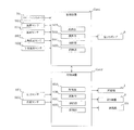
- FIG. 3 is a block diagram of a control function of hot water supply apparatus 100 according to the first embodiment.
- the control device Cnt1 includes an acquisition unit 50A that acquires data from various sensors, an operation unit 50B that performs an operation, a control unit 50C that controls an actuator, and a storage unit 50D that stores data.
- the acquisition unit 50A acquires a control instruction of the remote controller 70, a detection temperature of the temperature sensor SE3, a detection temperature of the temperature sensor SE4, a detection temperature of the temperature sensor SE5, and a detection temperature of the temperature sensor SE6.
- the acquiring unit 50A acquires the detected temperature of the upper temperature sensor SE7 and the detected temperature of the lower temperature sensor SE8.
- the calculation unit 50B has a first function of comparing the temperature detected by the upper temperature sensor SE7 with a predetermined threshold value.
- the calculation unit 50B also has a second function of comparing the temperature detected by the lower temperature sensor SE8 with a predetermined threshold value.
- Arithmetic unit 50B determines whether or not the boiling operation is to be performed by performing the first function and the second function.
- the control unit 50C controls the first pump 8, the second pump 5, and the flow path switching device 6.
- the control unit 50C can obtain the control target value of the first pump 8 and the control target value of the second pump 5 from the storage unit 50D.
- the control device Cnt2 includes an acquisition unit 60A that acquires data from various sensors, an operation unit 60B that performs an operation, a control unit 60C that controls an actuator, and a storage unit 60D that stores data.
- the acquisition unit 60A acquires the detected pressure of the pressure sensor SE1 and the detected temperature of the temperature sensor SE2.
- the calculation unit 60B has a function of calculating a control target value of the compressor 1. Furthermore, the calculation unit 60B has a function of calculating the degree of subcooling of the first heat exchanger 2.
- the calculation unit 60B calculates the condensation temperature of the refrigerant based on the pressure detected by the pressure sensor SE1.
- the calculation unit 60B calculates the degree of subcooling of the first heat exchanger 2 from the difference between the calculated condensation temperature and the temperature sensor SE2. Moreover, the calculating part 60B has a function which calculates the average heating capability which has determined the control target value of the compressor 1. The average heating capacity will be described later with reference to FIG.
- the controller 60C controls the compressor 1, the expansion device 3 and the blower 4A.
- the control unit 60C can obtain the control target value of the compressor 1 and the control target value of the expansion device 3 from the calculation unit 60B.
- control device Cnt1 and the control device Cnt2 are collectively referred to as a control device.
- Each functional unit included in the control device is configured by dedicated hardware or an MPU (Micro Processing Unit) that executes a program stored in a memory.
- the control device is dedicated hardware, the control device is, for example, a single circuit, a composite circuit, an application specific integrated circuit (ASIC), a field-programmable gate array (FPGA), or a combination thereof.
- ASIC application specific integrated circuit
- FPGA field-programmable gate array
- Each of the functional units realized by the control device may be realized by individual hardware, or each functional unit may be realized by one hardware.
- each function executed by the control device is realized by software, firmware, or a combination of software and firmware. Software and firmware are described as programs and stored in memory.
- the MPU implements each function of the control device by reading and executing the program stored in the memory.
- the memory is, for example, a nonvolatile or volatile semiconductor memory such as a RAM, a ROM, a flash memory, an EPROM, and an EEPROM.
- FIG. 4 is an operation explanatory view of the first boiling operation and the second boiling operation of the hot water supply apparatus 100 according to the first embodiment.
- the hot water supply apparatus 100 executes a first boiling operation which is performed at, for example, late night when the hot water supply load is small, and a second boiling operation which is performed when, for example, the evening and the night when the hot water supply load is large.
- a first boiling operation which is performed at, for example, late night when the hot water supply load is small
- a second boiling operation which is performed when, for example, the evening and the night when the hot water supply load is large.
- the order in which the refrigerant flows in each configuration is the same, and the order in which the heat medium flows in each configuration is also the same.
- the refrigerant will be described.
- the refrigerant is compressed by the compressor 1 and then discharged from the compressor 1.
- the refrigerant discharged from the compressor 1 flows into the refrigerant flow path 2B, and heats the heat medium of the first heat medium flow path 2A.
- the refrigerant is liquefied in the process of passing through the refrigerant flow path 2B.
- the refrigerant flowing out of the first heat medium channel 2A is decompressed by the expansion device 3.
- the refrigerant decompressed by the expansion device 3 is in a gas-liquid two-phase state.
- the refrigerant flowing out of the expansion device 3 flows into the heat exchanger 4 and absorbs heat from the air.
- the refrigerant is gasified in the process of passing through the heat exchanger 4.
- the heat medium is pressurized by the second pump 5 and discharged from the second pump 5.
- the heat medium discharged from the second pump 5 flows into the first heat medium channel 2A through the pipe p2, and is heated by the refrigerant.
- the heat medium having flowed out of the first heat medium channel 2A flows into the flow path switching device 6 through the pipe p3.
- the heat medium flows from the inlet a to the outlet b.
- the exit c is closed. Therefore, the heat medium does not flow from the inlet a to the outlet c.
- the heat medium having flowed out from the outlet b flows into the second heat medium channel 7B through the pipe p4, and heats the heat medium of the third heat medium channel 7A of the primary circuit C1.
- the heat medium having flowed out of the second heat medium channel 7B returns to the second pump 5 through the pipe p6 and the pipe p1.
- the heat medium is pressurized by the first pump 8 and discharged from the first pump 8.
- the heat medium discharged from the first pump 8 flows into the hot water storage tank 9 through the inflow pipe p8.
- the heat medium of the hot water storage tank 9 flows into the third heat medium channel 7A through the outflow pipe p9, and is heated by the heat medium of the second heat medium channel 7B of the primary circuit C1.
- the heat medium flowing out of the third heat medium channel 7A returns to the first pump 8 through the pipe p7.
- FIG. 5 is a control flowchart of water heating apparatus 100 according to the first embodiment.
- FIG. 6 is an explanatory view of the temperature of the hot water storage tank 9 at the start of the first boiling operation and the temperature of the hot water storage tank 9 at the start of the second boiling operation.
- the controller Cnt1 starts the control flow according to the first boiling operation and the second boiling operation (step S0).
- the present control flow starts every predetermined time.
- the controller Cnt1 determines whether the temperature detected by the upper temperature sensor SE7 is less than the first boiling temperature Tus1 (step S101).
- the first boiling temperature Tus1 is 40 ° C., for example.
- the control device Cnt1 executes the first boiling operation (step S102). That is, the control device Cnt1 starts the operation of the first pump 8 and the second pump 5, and the control device Cnt1 outputs an instruction to start the operation of the actuator such as the compressor 1 to the control device Cnt2.
- the control device Cnt2 that has received the instruction from the control device Cnt1 starts the operation of the compressor 1 and the blower 4A.
- the control device Cnt1 determines whether the temperature detected by the lower temperature sensor SE8 is higher than the first stop temperature Tde1 (step S103).
- the first stop temperature Tde1 is 55 ° C., for example.
- the controller Cnt1 stops the first pump 8 and the second pump 5, and the controller Cnt2 controls the compressor 1 and the blower 4A. Are stopped (step S108).
- step S104 the controller Cnt1 determines whether the temperature detected by the upper temperature sensor SE7 is less than the second boiling temperature Tus2.
- the second boiling temperature Tus2 is higher than the first boiling temperature Tus1, and is 50 ° C., for example. If the temperature detected by the upper temperature sensor SE7 is less than the second boiling temperature Tus2, the controller Cnt1 determines whether the temperature detected by the lower temperature sensor SE8 is less than the third boiling temperature Tds2. (Step S105).
- FIG. 6 the second boiling temperature Tus2 is higher than the first boiling temperature Tus1, and is 50 ° C., for example.
- the third boiling temperature Tds2 is lower than the first boiling temperature Tus1 and the second boiling temperature Tus2, for example, 15 ° C. If the temperature detected by the lower temperature sensor SE8 is less than the third boiling temperature Tds2, the control device Cnt1 executes the second boiling operation (step S106). That is, the control device Cnt1 starts the operation of the first pump 8 and the second pump 5, and the control device Cnt1 outputs an instruction to start the operation of the actuator such as the compressor 1 to the control device Cnt2.
- the control device Cnt2 that has received the instruction from the control device Cnt1 starts the operation of the compressor 1 and the blower 4A.
- the control device Cnt1 determines whether the temperature detected by the upper temperature sensor SE7 is higher than the second stop temperature Tue2 (step S107).
- the second stop temperature Tue2 is higher than the first stop temperature Tde1, for example, 60 ° C.
- the controller Cnt1 stops the first pump 8 and the second pump 5, and the controller Cnt2 controls the compressor 1 and the blower 4A. Are stopped (step S108).
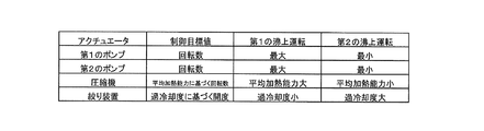
- FIG. 7 is an explanatory view of a control target value of the actuator in the first boiling operation and a control target value of the actuator in the second boiling operation.
- the control target value of the actuator in the first boiling operation is defined as follows. That is, the control target value of the first pump 8 is the pump rotational speed x1, the control target value of the second pump 5 is the pump rotational speed x2, and the control target value of the compressor 1 is the compressor rotational speed x3.
- the control target value of the device 3 is set to the opening degree x4.
- the pump rotational speed x1 corresponds to the first pump rotational speed.
- the pump rotational speed x2 corresponds to the third pump rotational speed.
- the pump rotational speed x1 and the pump rotational speed x2 are predetermined rotational speeds.
- the pump rotational speed x1 and the pump rotational speed x2 are stored in the storage unit 50D.
- the pump rotational speed x1 is, for example, the maximum rotational speed of the first pump 8.
- the pump rotational speed x 2 is, for example, the maximum rotational speed of the second pump 5.
- a first average heating capacity is a value obtained by dividing the amount of heat increase of the hot water storage tank 9 from the start to the end of the first boiling operation by the time from the start to the end of the first boiling operation.
- the second average is a value obtained by dividing the amount of heat increase of the hot water storage tank 9 from the start to the end of the second boiling operation by the time from the start to the end of the second boiling operation. It is defined as heating capacity.
- the compressor rotational speed x3 is the first average heating than the second average heating capacity. It is predetermined that the ability is greater.
- the temperature conditions are, for example, the outside air temperature and the tap water temperature.
- the degree of subcooling of the first heat exchanger 2 in the first boiling operation is a first degree of subcooling
- the degree of subcooling of the first heat exchanger 2 in the second boiling operation is a second Degree of supercooling.
- the calculation unit 60B calculates the first degree of subcooling and the second degree of subcooling.
- the storage unit 60D stores a first target degree of supercooling in the first boiling operation and a second target degree of supercooling in the second boiling operation.
- the first target degree of supercooling is smaller than the second target degree of supercooling.
- the opening degree x4 is set such that the first degree of subcooling is smaller than the second degree of subcooling.
- the control target value of the actuator in the second boiling operation can be described in the same manner as the control target value of the actuator in the first boiling operation, as described above.
- the control target value of the actuator in the second boiling operation describes a portion different from the control target value of the actuator in the first boiling operation.
- the control target value of the actuator in the second boiling operation is defined as follows.
- a control target value of the first pump 8 is a pump rotational speed y1
- a control target value of the second pump 5 is a pump rotational speed y2
- a control target value of the compressor 1 is a compressor rotational speed y3.
- the control target value of is set to the opening degree y4.
- the pump rotational speed y1 corresponds to the second pump rotational speed.
- the pump rotational speed y2 corresponds to the fourth pump rotational speed.
- the pump rotational speed y1 is, for example, the minimum rotational speed of the first pump 8.
- the pump rotational speed x 2 is, for example, the minimum rotational speed of the second pump 5.
- the compressor rotational speed y3 is set such that the first average heating capacity is larger than the second average heating capacity.
- the opening degree y4 is set so that the first degree of subcooling is smaller than the second degree of subcooling.
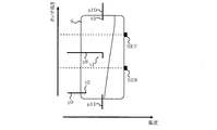
- FIG. 8 shows the temperature distribution of the hot water storage tank 9 at the start of the first boiling operation.
- FIG. 9 shows the temperature distribution of the hot water storage tank 9 when the temperature of the hot water storage tank 9 is raised by the first boiling operation.
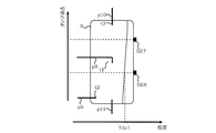
- FIG. 10 shows the temperature distribution of the hot water storage tank 9 at the end of the first boiling operation.
- FIG. 8 when the temperature of the heat medium of the hot water storage tank 9 is lowered due to the heat release of the hot water storage tank 9, the temperature of the heat medium of the hot water storage tank 9 rises gently from the lower side to the upper side of the hot water storage tank 9. doing. That is, the difference between the temperature of the heat medium on the upper side of the hot water storage tank 9 and the temperature of the heat medium on the lower side of the hot water storage tank 9 is small.
- the detected temperature of the upper temperature sensor SE7 is lower than the first boiling temperature Tus1. For this reason, the hot water supply apparatus 100 executes the first boiling operation.
- the heated heat medium flows into the hot water storage tank 9 from the inflow pipe p8.
- the heated heat medium spreads over the entire hot water storage tank 9 as described later with reference to FIG.
- the temperature of the entire heat medium of the hot water storage tank 9 rises.
- the detected temperature of the lower temperature sensor SE8 exceeds the first stop temperature Tde1. Therefore, the hot water supply apparatus 100 ends the first boiling operation.
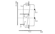
- FIG. 11 shows the temperature distribution of the hot water storage tank 9 at the start of the second boiling operation.
- FIG. 12 shows the temperature distribution of the hot water storage tank 9 when the temperature of the hot water storage tank 9 is raised by the second boiling operation.
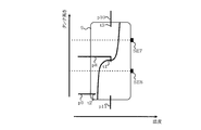
- FIG. 13 shows the temperature distribution of the hot water storage tank 9 at the end of the second boiling operation.
- FIG. 11 when the temperature of the heat medium of the hot water storage tank 9 is lowered due to the increase of the usage amount of hot water supply, the temperature of the heat medium of the hot water storage tank 9 rapidly increases from the lower side to the upper side of the hot water storage tank 9 It is rising. That is, the difference between the temperature of the heat medium on the upper side of the hot water storage tank 9 and the temperature of the heat medium on the lower side of the hot water storage tank 9 is large.
- a place where the temperature of the heat medium rises rapidly corresponds to the temperature stratification of the hot water storage tank 9.
- the detected temperature of the upper temperature sensor SE7 is less than the second boiling temperature Tus2, and the detected temperature of the lower temperature sensor SE8 is less than the third boiling temperature Tds2. Therefore, the hot water supply apparatus 100 executes the second boiling operation.
- the heated heat medium is mainly supplied to the upper portion of the hot water storage tank 9 as described later with reference to FIG.
- the temperature of the heat medium in the upper part of the hot water storage tank 9 rises.
- the detected temperature of the upper temperature sensor SE7 exceeds the second stop temperature Tue2. Therefore, the hot water supply apparatus 100 ends the second boiling operation.
- FIG. 14 shows the flow of the heat medium of the hot water storage tank 9 in the first boiling operation. Since the rotation speed of the first pump 8 in the first boiling operation is higher than the rotation speed of the first pump 8 in the second boiling operation, from the second opening t1 in the first boiling operation The flow velocity of the heat medium flowing into the hot water storage tank 9 is high. Therefore, the heat medium flowing into the hot water storage tank 9 from the second opening t1 flows to the lower part of the hot water storage tank 9, and then flows to the upper part of the hot water storage tank 9 by buoyancy. As described above, in the first boiling operation, the heated heat medium flows in the entire hot water storage tank 9, and thus the heated heat medium spreads in the entire water storage tank 9. As a result, the temperature of the entire heat medium of the hot water storage tank 9 rises.
- FIG. 15 shows the flow of the heat medium of the hot water storage tank 9 in the second boiling operation.
- the rotation speed of the second pump 5 in the second boiling operation is lower than the rotation speed of the second pump 5 in the first boiling operation, and the temperature at the outlet of the first heat medium flow path 2A rises It's easy to do.
- a high temperature heat medium is supplied to the second heat medium channel 7B. Therefore, the number of rotations of the first pump 8 in the second boiling operation is lower than the number of rotations of the first pump 8 in the first boiling operation, and a high temperature is applied to the second heat medium passage 7B.
- the temperature of the outlet of the third heat medium channel 7A is also likely to rise.
- the buoyancy acts more greatly. Furthermore, the rotation speed of the first pump 8 in the second boiling operation is lower than the rotation speed of the first pump 8 in the first boiling operation, and the second opening in the second boiling operation The flow velocity of the heat medium flowing into the hot water storage tank 9 from t1 is low.
- the heat transfer medium flowing into the hot water storage tank 9 from the second opening t1 in the second boiling operation has a greater buoyancy and has a lower flow velocity, so the second heating operation from the second opening t1 in the second boiling operation
- the heat medium flowing into the hot water storage tank 9 does not flow to the lower part of the hot water storage tank 9 but flows to the upper part of the hot water storage tank 9.
- the temperature of the heat medium in the upper part of the hot water storage tank 9 rises. That is, the temperature of the heat medium at the upper portion of the hot water storage tank 9 in the second boiling operation tends to be higher than the temperature of the heat medium at the upper portion of the hot water storage tank 9 in the first boiling operation.
- the heat medium whose temperature rise in the lower portion of the hot water storage tank 9 is suppressed in the second boiling operation flows out of the hot water storage tank 9 from the outflow pipe p9.
- the water heater 100 includes an upper temperature sensor SE7 and a lower temperature sensor SE8. Therefore, in the control device Cnt1, the temperature of the heat medium of the hot water storage tank 9 is decreased due to the first temperature distribution in which the temperature of the heat medium of the hot water storage tank 9 is decreased due to heat release of the hot water storage tank 9 The second temperature distribution can be determined more accurately.
- the control device Cnt1 can more accurately determine the first temperature distribution and the second temperature distribution.
- the control device Cnt1 can more accurately determine the first temperature distribution and the second temperature distribution. Therefore, when the temperature of the heat medium of the hot water storage tank 9 is lowered due to the increase of the usage amount of the hot water supply, the control device Cnt1 can execute the second boiling operation more reliably. That is, in the situation where the end of the day approaches, such as evening and night, when the hot water supply apparatus 100 boils the entire heat medium of the hot water storage tank 9, the possibility of generating hot water which is not used increases. However, since the control device Cnt1 can more reliably execute the second boiling operation, it is possible to suppress the generation of hot water that is not used. That is, since the hot water supply apparatus 100 can suppress the generation of the hot water that is not used, the power consumption can be suppressed.
- the control device Cnt1 can perform the first boiling operation more reliably. That is, although the total heat quantity of the hot water storage tank 9 is greatly reduced as in the middle of the night, the hot water supply apparatus 100 can boil the whole heat medium while the hot water supply load is small.
- the control device Cnt1 uses the second boiling temperature Tus2 higher than the first boiling temperature Tus1 for determining the start of the second boiling operation. Therefore, even if the temperature of the heat medium at the upper part of the hot water storage tank 9 is high, that is, even when a certain amount of high temperature heat medium can be secured in the hot water storage tank 9, the controller Cnt1 performs the second boiling operation Can be performed. Accordingly, it is possible to avoid that the hot water supply device 100 can not supply the high-temperature heat medium to the utilization unit U in a situation where the usage amount of the heat medium of the hot water storage tank 9 is increased as in the evening and night.
- the controller Cnt1 stops the first pump 8 when the temperature detected by the lower temperature sensor SE8 becomes higher than the first stop temperature Tde1 while performing the first boiling operation. That is, the control device Cnt1 uses the lower temperature sensor SE8 instead of the upper temperature sensor SE7 to determine the end of the first boiling operation.
- the temperature of the heat medium in the lower part of the hot water storage tank 9 is lower than the temperature of the heat medium in the upper part of the hot water storage tank 9. For this reason, when the control device Cnt1 uses the lower temperature sensor SE8 to determine the end of the first boiling operation, the hot water supply device 100 can more surely boil the whole heat medium of the hot water storage tank 9.
- the controller Cnt1 stops the first pump 8 when the temperature detected by the upper temperature sensor SE7 becomes higher than the second stop temperature Tue2 while performing the second boiling operation. That is, the control device Cnt1 uses the upper temperature sensor SE7 instead of the lower temperature sensor SE8 to determine the end of the first heating operation.
- the heated heat medium flows to the upper part of the hot water storage tank 9. Therefore, when the control device Cnt1 uses the upper temperature sensor SE7 to determine the end of the second boiling operation, the hot water supply device 100 can more surely boil the heat medium in the upper portion of the hot water storage tank 9.
- the second stop temperature Tue2 is higher than the first stop temperature Tde1.
- the temperature of the heat medium at the upper portion of the hot water storage tank 9 in the second boiling operation is higher than the temperature of the heat medium at the upper portion of the hot water storage tank 9 in the first boiling operation. It's easy to do. Therefore, even if the second stop temperature Tue2 is equal to or lower than the first stop temperature Tde1, the control device Cnt1 performs the second boiling operation even though the amount of the heat medium boiled is not very large. The possibility of ending is increased. For this reason, since 2nd stop temperature Tue2 is higher than 1st stop temperature Tde1, the hot-water supply apparatus 100 can ensure the heat medium boiled up in the 2nd boiling operation.
- the control device Cnt1 sets not only the first pump 8 but also the second pump 5 to a maximum number of revolutions. That is, the rotation speed of the first pump 8 in the first boiling operation is higher than the rotation speed of the first pump 8 in the second boiling operation, and the second pump in the first boiling operation The rotational speed of 5 is higher than the rotational speed of the second pump 5 in the second boiling operation.
- the control device Cnt1 increases the flow rate of the heat medium of the primary circuit C1 as the flow rate of the heat medium of the secondary circuit C2 increases. Thereby, the heat exchange efficiency in the first heat exchanger 2 and the heat exchange efficiency in the first heat exchanger 2 are improved.
- the upper temperature sensor SE7 is provided below the first opening t3 of the hot water discharge piping p10 and above the second opening t1 of the inflow piping p8.
- the lower temperature sensor SE8 is provided below the second opening t1 of the inflow piping p8 and above the third opening t2 of the outflow piping p9. Therefore, the upper temperature sensor SE7 can be easily positioned above the temperature stratification of the hot water storage tank 9, and the lower temperature sensor SE8 can be easily positioned below the temperature stratification of the hot water storage tank 9. Therefore, the control device Cnt1 can more accurately determine the first temperature distribution and the second temperature distribution.
- the controller Cnt1 controls the compressor 1 such that the second average heating capacity is smaller than the first average heating capacity.
- the rotational speed of the second pump 5 is suppressed, and is, for example, the minimum rotational speed. That is, in the second boiling operation, the flow rate of the heat medium of the primary circuit C1 is suppressed.
- the control device Cnt1 suppresses the rotational speed of the compressor 1 in the second boiling operation, the hot water supply device 100 can prevent the discharge pressure of the compressor 1 from rising excessively.
- the control device Cnt1 controls the expansion device 3 so that the second degree of subcooling in the second boiling operation becomes larger than the first degree of subcooling in the first boiling operation. ing.
- the rotational speed of the second pump 5 is suppressed, and is, for example, the minimum rotational speed. Since the flow rate of the heat medium flowing into the first heat exchanger 2 is suppressed, the difference between the inlet temperature of the heat medium of the first heat exchanger 2 and the outlet temperature of the heat medium of the first heat exchanger 2 is There is a tendency to increase. Therefore, the control device Cnt1 increases the degree of subcooling of the first heat exchanger 2 in the second boiling operation.
- the outlet temperature of the refrigerant of the first heat exchanger 2 is further lowered. That is, the difference between the inlet temperature of the refrigerant of the first heat exchanger 2 and the outlet temperature of the refrigerant of the first heat exchanger 2 is increased. Thereby, the heat exchange efficiency between the refrigerant and the heat medium in the first heat exchanger 2 is improved.
- FIG. 16 is a schematic block diagram of a modification of the hot water supply apparatus 100 according to the first embodiment.
- FIG. 17 is a block diagram of control functions of a modification of hot water supply apparatus 100 according to the first embodiment.
- the heat medium circuit C of the tank unit 30 of the hot water supply apparatus 100 includes the primary circuit C1 and the secondary circuit C2.
- the heat medium circuit C3 of the tank unit 30 of the hot water supply apparatus 100B according to the modification does not include a plurality of circuits. That is, although the heat medium circuit C is provided with the first heat exchanger 2 and the first pump 8, the heat medium circuit C3 is provided with the second pump 5, the flow path switching device 6, and the second The heat exchanger 7 is not provided. Even in the case of the hot water supply apparatus 100B, the same operation and effect as the hot water supply apparatus 100 according to the first embodiment can be obtained.
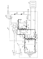
- FIG. 18 is a schematic block diagram of a hot water supply apparatus 200 according to the second embodiment.
- FIG. 19 is a block diagram of a control function of hot water supply device 200 according to the second embodiment.
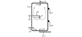
- the secondary circuit C22 of the heat medium circuit C20 of the hot water supply apparatus 200 includes the flow path switching device 10 that switches the flow path of the heat medium. Further, the inflow piping p8b of the secondary circuit C22 is connected to the hot water storage tank 9, and is connected to a first inflow piping p82 through which the heat medium flows during the first boiling operation, and to the hot water storage tank 9; A second inflow pipe p83 through which the heat medium flows during the boiling operation is provided.
- the flow path switching device 10 has an inlet d connected to the discharge portion of the first pump 8, a first outlet f connected to the hot water storage tank 9 via the first inflow pipe p82, and a second inflow.
- the first inflow pipe p82 has the same configuration as the inflow pipe p8 described in the first embodiment.
- the second inflow piping p83 includes a fourth opening t5 provided in the hot water storage tank 9.
- the second opening t1 of the first inflow piping p82 is provided below the first opening t3 of the hot water discharge piping p10 and the fourth opening t5 of the second inflow piping p83.
- the third opening t2 of the outflow pipe p9 is provided below the second opening t1 of the first inflow pipe p82.
- the control unit 50C of the control device Cnt1 controls the flow path switching device 10 in addition to the first pump 8, the second pump 5 and the flow path switching device 6.
- FIG. 20 is an operation explanatory view of a first boiling operation of the hot water supply apparatus 200 according to the second embodiment.
- the control device Cnt1 opens the first outlet f of the flow channel switching device 10 and closes the second outlet e of the flow channel switching device 10. Therefore, the heat medium of the secondary circuit C22 flows into the hot water storage tank 9 via the first pump 8, the inlet d, the first outlet f, and the first inflow piping p82.
- FIG. 21 is an operation explanatory view of a second boiling operation of the hot water supply apparatus 200 according to the second embodiment.
- the controller Cnt1 closes the first outlet f of the flow channel switching device 10 and opens the second outlet e of the flow channel switching device 10. Therefore, the heat medium of the secondary circuit C22 flows into the hot water storage tank 9 through the first pump 8, the inlet d, the second outlet e, and the second inflow piping p83.
- the fourth opening t5 of the second inflow pipe p83 is provided above the second opening t1 of the first inflow pipe p82. That is, the fourth opening t5 of the second inflow pipe p83 is provided at the upper portion in the hot water storage tank 9.
- the fourth opening t5 of the second inflow pipe p83 is located above the temperature stratification. Therefore, in the second boiling operation, the heated heat medium flows from the fourth opening t5 into a portion of the hot water storage tank 9 above the temperature stratification. Then, the heat medium flowing into the upper part of the temperature stratification is suppressed from flowing downward because the temperature is high. Therefore, the hot water supply apparatus 200 can hold the thermal stratification of the hot water storage tank 9 more reliably. That is, the hot water supply apparatus 200 can suppress that the temperature of the heat medium used for hot water supply located above the temperature stratification falls.
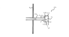
- FIG. 22 is a schematic block diagram of a hot water supply apparatus 300 according to the third embodiment.
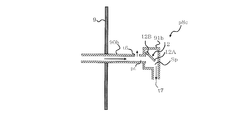
- FIG. 23 is an explanatory diagram of the hot water storage tank 9 and the inflow piping p8c of the hot water supply apparatus 300 according to the third embodiment.
- FIG. 24 is an enlarged view of the inflow piping p8c shown in FIG.
- the inflow piping p8c of the secondary circuit C32 of the heat medium circuit C30 of the hot water supply apparatus 300 is different in configuration from the inflow piping p8 of the secondary circuit C2 of the heat medium circuit C described in the first embodiment.
- the other configuration of heat medium circuit C30 is the same as the configuration of heat medium circuit C of water heating apparatus 100.
- the inflow piping p8c is provided in the first inlet t6 provided in the hot water storage tank 9 and in the hot water storage tank 9, and the heat medium is provided from the first inlet t6.
- a second inlet t7 provided on the downstream side in the flow direction.
- the first inlet t6 and the second inlet t7 are openings formed in the inlet pipe p8c.
- the opening area of the first inlet t6 is smaller than the opening area of the second inlet t7.
- the inflow piping p8c is provided downstream of the first inlet t6 in the flow direction of the heat medium and upstream of the second inlet t7 in the flow direction of the heat medium, and the inflow piping p8c
- An open / close mechanism unit 12 configured to open and close according to the flow rate of the flowing heat medium is provided.
- the inflow piping p8c is provided with a space Sp in which the opening / closing mechanism 12 is provided, and a flow path pt provided on the upstream side in the flow direction of the heat medium than the space Sp and opening / closing the opening / closing mechanism 12 It is formed.
- the space Sp is provided downstream of the first inlet t6 in the flow direction of the heat medium and upstream of the second inlet t7 in the flow direction of the heat medium.
- the opening and closing mechanism 12 includes an opening and closing part 12A for opening and closing the flow path pt, and a hinge part 12B for rotatably supporting the opening and closing part 12A.
- the opening / closing portion 12A closes the flow path pt by the weight of the opening / closing portion 12A.
- the inflow piping p8c is provided with a horizontal portion 90b extending in parallel to the horizontal surface and a vertical portion 91b extending in parallel in the vertical direction.
- the horizontal portion 90b is provided with a flow path pt and a first inlet t6.
- a space Sp, a second inlet t7, and an opening / closing mechanism 12 are provided in the vertical portion 91b.
- FIG. 25 shows the opening / closing mechanism 12 in the first boiling operation.
- the rotational speed of the first pump 8 in the first boiling operation is higher than the rotational speed of the first pump 8 in the second boiling operation.
- the pressure of the heat medium of the flow path pt in the first boiling operation becomes higher than the pressure of the heat medium of the flow path pt in the second boiling operation. Therefore, the heat medium of the flow path pt in the first boiling operation pushes up the open / close portion 12A.
- the heat medium of the flow path pt flows into the hot water storage tank 9 through the space Sp and the second inlet t7.
- a part of the heat medium flowing through the flow path pt flows into the hot water storage tank 9 from the first inlet t6.
- FIG. 26 shows the opening / closing mechanism 12 in the second boiling operation. Since the rotational speed of the first pump 8 in the second boiling operation is kept low, the heat medium of the flow path pt in the second boiling operation can not push up the opening / closing part 12A. That is, the flow path pt is closed to the opening / closing part 12A. Therefore, the heat medium of the flow path pt flows into the hot water storage tank 9 from the first inlet t6.
- the inflow pipe p8c is provided with an open / close mechanism unit 12 configured to open and close according to the flow rate of the heat medium.
- the flow rate of the heat medium in the inflow piping p8c in the first boiling operation is larger than the flow rate of the heat medium in the inflow piping p8c in the second boiling operation.
- the heat medium pushes up the opening and closing part 12A of the opening and closing mechanism part 12, and the flow path pt is opened. Then, a part of the heat medium flowing in the flow path pt flows downward from the second inlet t 7 and reaches the inside of the hot water storage tank 9.
- the heat medium flowing into the hot water storage tank 9 from the second inlet t7 flows to the lower portion in the hot water storage tank 9 and then flows to the upper portion in the hot water storage tank 9 by buoyancy.
- the temperature of the entire heat medium of the hot water storage tank 9 rises.
- the other part of the heat medium flowing in the flow path pt flows upward from the first inlet t6 and reaches the inside of the hot water storage tank 9.
- the other part of the heat medium flowing through the flow path pt contributes to the temperature rise of the heat medium in the upper part of the hot water storage tank 9.
- the heat medium can not push up the opening and closing part 12A of the opening and closing mechanism part 12, and the flow path pt is closed. Therefore, the heat medium flowing in the flow path pt flows upward from the first inlet t6 and reaches the inside of the hot water storage tank 9. Further, since the heat medium flowing in the flow path pt is heated by the second heat exchanger 7, a large buoyancy acts on the heat medium that has reached the hot water storage tank 9 from the flow path pt. As a result, the heat medium flowing into the hot water storage tank 9 from the first inlet t6 does not easily flow to the lower portion in the hot water storage tank 9, and flows to the upper portion in the hot water storage tank 9.
- the hot water supply apparatus 200 can hold the thermal stratification of the hot water storage tank 9 more reliably. That is, the hot water supply apparatus 300 can suppress that the temperature of the heat medium used for hot water supply located above the temperature stratification falls.
- the opening and closing mechanism 12 can open and close the flow path pt. Therefore, complication of the mechanism of the inflow piping p8c can be avoided.
- the action of the weight of the opening / closing portion 12A is used to open and close the flow path pt, but the present invention is not limited to this action.
- the elastic force of the spring and the magnetic force of the magnet may be used to open and close the flow path pt.
- the opening area of the second inlet t7 is larger than the opening area of the first inlet t6. Therefore, in the first boiling operation, the flow rate of the heat medium flowing into the hot water storage tank 9 from the second inlet t7 is the flow rate of the heat medium flowing into the hot water storage tank 9 from the first inlet t6. It will be more than the flow rate. Therefore, the heat medium flowing through the inflow piping p8c mainly flows into the hot water storage tank 9 from the second inlet t7. The heat medium flowing into the hot water storage tank 9 flows to the lower part of the hot water storage tank 9 and then flows to the upper part of the hot water storage tank 9 by buoyancy. That is, since the opening area of the second inlet t7 is larger than the opening area of the first inlet t6, the heat medium heated in the first boiling operation easily spreads over the entire hot water storage tank 9.
- the hot water supply device 300 can hold the thermal stratification of the hot water storage tank 9 more reliably. That is, the hot water supply apparatus 300 can suppress that the temperature of the heat medium used for hot water supply located above the temperature stratification falls.
Abstract
Selon la présente invention, un dispositif de commande réalise un premier actionnement d'ébullition destiné à faire fonctionner une première pompe à une première vitesse de rotation de la pompe lorsque la température d'une partie supérieure est inférieure à une première température d'ébullition, et un second actionnement d'ébullition destiné à faire fonctionner la première pompe à une seconde vitesse de rotation de la pompe, inférieure à la première vitesse de rotation de la pompe, lorsque la température de la partie supérieure est inférieure à une deuxième température d'ébullition supérieure à la première température d'ébullition et lorsque la température d'une partie inférieure est inférieure à une troisième température d'ébullition inférieure à la première température d'ébullition.
Priority Applications (5)
| Application Number | Priority Date | Filing Date | Title |
|---|---|---|---|
| PCT/JP2017/025839 WO2019016845A1 (fr) | 2017-07-18 | 2017-07-18 | Dispositif d'alimentation en eau chaude |
| JP2019530253A JP6775688B2 (ja) | 2017-07-18 | 2017-07-18 | 給湯装置 |
| EP17918515.2A EP3657091B1 (fr) | 2017-07-18 | 2017-07-18 | Dispositif d'alimentation en eau chaude |
| ES17918515T ES2898909T3 (es) | 2017-07-18 | 2017-07-18 | Dispositivo de suministro de agua caliente |
| CN201780092954.1A CN110869680B (zh) | 2017-07-18 | 2017-07-18 | 供热水装置 |
Applications Claiming Priority (1)
| Application Number | Priority Date | Filing Date | Title |
|---|---|---|---|
| PCT/JP2017/025839 WO2019016845A1 (fr) | 2017-07-18 | 2017-07-18 | Dispositif d'alimentation en eau chaude |
Publications (1)
| Publication Number | Publication Date |
|---|---|
| WO2019016845A1 true WO2019016845A1 (fr) | 2019-01-24 |
Family
ID=65015455
Family Applications (1)
| Application Number | Title | Priority Date | Filing Date |
|---|---|---|---|
| PCT/JP2017/025839 WO2019016845A1 (fr) | 2017-07-18 | 2017-07-18 | Dispositif d'alimentation en eau chaude |
Country Status (5)
| Country | Link |
|---|---|
| EP (1) | EP3657091B1 (fr) |
| JP (1) | JP6775688B2 (fr) |
| CN (1) | CN110869680B (fr) |
| ES (1) | ES2898909T3 (fr) |
| WO (1) | WO2019016845A1 (fr) |
Citations (9)
| Publication number | Priority date | Publication date | Assignee | Title |
|---|---|---|---|---|
| JP2006336937A (ja) * | 2005-06-01 | 2006-12-14 | Denso Corp | 貯湯式給湯装置 |
| JP2007139275A (ja) * | 2005-11-16 | 2007-06-07 | Denso Corp | ヒートポンプ式給湯装置 |
| JP2007327728A (ja) * | 2006-06-09 | 2007-12-20 | Hitachi Appliances Inc | ヒートポンプ給湯システム |
| WO2012121382A1 (fr) * | 2011-03-10 | 2012-09-13 | ダイキン工業株式会社 | Chauffe-eau du type pompe à chaleur |
| WO2013084301A1 (fr) * | 2011-12-06 | 2013-06-13 | 三菱電機株式会社 | Système de chauffage de type pompe à chaleur/d'alimentation en eau chaude |
| JP2015055389A (ja) * | 2013-09-11 | 2015-03-23 | 三菱重工業株式会社 | 給湯システムおよびその制御方法 |
| JP2015224796A (ja) | 2014-05-26 | 2015-12-14 | 三菱電機株式会社 | 給湯装置 |
| JP2016090093A (ja) * | 2014-10-31 | 2016-05-23 | 三菱電機株式会社 | 給湯機 |
| JP2017096601A (ja) * | 2015-11-27 | 2017-06-01 | 株式会社ノーリツ | 貯湯式給湯装置 |
Family Cites Families (8)
| Publication number | Priority date | Publication date | Assignee | Title |
|---|---|---|---|---|
| JP2982615B2 (ja) * | 1994-06-24 | 1999-11-29 | 松下電器産業株式会社 | ヒートポンプ給湯機 |
| JP4678518B2 (ja) * | 2006-01-24 | 2011-04-27 | 株式会社デンソー | 貯湯式給湯装置 |
| CN201014742Y (zh) * | 2007-02-08 | 2008-01-30 | 吴江 | 一种热泵式热水器 |
| CN101936603B (zh) * | 2010-09-02 | 2012-07-18 | 东莞市康源节能科技有限公司 | 一种分体速热式热泵热水器的控制方法及其热水器 |
| CN202040977U (zh) * | 2011-04-26 | 2011-11-16 | 珠海格力电器股份有限公司 | 一种储水式热泵热水器 |
| JP2014190601A (ja) * | 2013-03-27 | 2014-10-06 | Panasonic Corp | ヒートポンプ式給湯装置 |
| JP5893695B1 (ja) * | 2014-09-10 | 2016-03-23 | ファナック株式会社 | 物品搬送システム |
| CN107763726B (zh) * | 2017-11-17 | 2023-10-27 | 珠海格力电器股份有限公司 | 热泵系统 |
-
2017
- 2017-07-18 ES ES17918515T patent/ES2898909T3/es active Active
- 2017-07-18 JP JP2019530253A patent/JP6775688B2/ja active Active
- 2017-07-18 CN CN201780092954.1A patent/CN110869680B/zh active Active
- 2017-07-18 WO PCT/JP2017/025839 patent/WO2019016845A1/fr unknown
- 2017-07-18 EP EP17918515.2A patent/EP3657091B1/fr active Active
Patent Citations (9)
| Publication number | Priority date | Publication date | Assignee | Title |
|---|---|---|---|---|
| JP2006336937A (ja) * | 2005-06-01 | 2006-12-14 | Denso Corp | 貯湯式給湯装置 |
| JP2007139275A (ja) * | 2005-11-16 | 2007-06-07 | Denso Corp | ヒートポンプ式給湯装置 |
| JP2007327728A (ja) * | 2006-06-09 | 2007-12-20 | Hitachi Appliances Inc | ヒートポンプ給湯システム |
| WO2012121382A1 (fr) * | 2011-03-10 | 2012-09-13 | ダイキン工業株式会社 | Chauffe-eau du type pompe à chaleur |
| WO2013084301A1 (fr) * | 2011-12-06 | 2013-06-13 | 三菱電機株式会社 | Système de chauffage de type pompe à chaleur/d'alimentation en eau chaude |
| JP2015055389A (ja) * | 2013-09-11 | 2015-03-23 | 三菱重工業株式会社 | 給湯システムおよびその制御方法 |
| JP2015224796A (ja) | 2014-05-26 | 2015-12-14 | 三菱電機株式会社 | 給湯装置 |
| JP2016090093A (ja) * | 2014-10-31 | 2016-05-23 | 三菱電機株式会社 | 給湯機 |
| JP2017096601A (ja) * | 2015-11-27 | 2017-06-01 | 株式会社ノーリツ | 貯湯式給湯装置 |
Non-Patent Citations (1)
| Title |
|---|
| See also references of EP3657091A4 |
Also Published As
| Publication number | Publication date |
|---|---|
| EP3657091B1 (fr) | 2021-10-27 |
| CN110869680A (zh) | 2020-03-06 |
| JPWO2019016845A1 (ja) | 2020-02-06 |
| ES2898909T3 (es) | 2022-03-09 |
| EP3657091A4 (fr) | 2020-09-02 |
| JP6775688B2 (ja) | 2020-10-28 |
| CN110869680B (zh) | 2021-05-25 |
| EP3657091A1 (fr) | 2020-05-27 |
Similar Documents
| Publication | Publication Date | Title |
|---|---|---|
| JP5642207B2 (ja) | 冷凍サイクル装置及び冷凍サイクル制御方法 | |
| JP5533491B2 (ja) | 冷凍サイクル装置及び温水暖房装置 | |
| JP6370136B2 (ja) | 温水装置及び温水装置における異常通知方法 | |
| EP3163176A1 (fr) | Système de chauffage et de fourniture d'eau chaude | |
| JP6545375B2 (ja) | ヒートポンプ式空調給湯装置 | |
| JP6546813B2 (ja) | 空気調和機 | |
| JP6515859B2 (ja) | 貯湯式給湯システム | |
| JP6320060B2 (ja) | 冷凍サイクル装置 | |
| JP5605296B2 (ja) | ハイブリッド式給湯装置 | |
| JP6297072B2 (ja) | ヒートポンプ式給湯装置 | |
| JP5585358B2 (ja) | 貯湯式給湯機 | |
| JP5409318B2 (ja) | ヒートポンプ装置及びヒートポンプ装置の運転方法 | |
| JP5482724B2 (ja) | ハイブリッド式給湯装置 | |
| US20110011943A1 (en) | Heating installation and method for controlling the heating installation | |
| JP2012132583A (ja) | ヒートポンプ式暖房給湯装置 | |
| WO2019016845A1 (fr) | Dispositif d'alimentation en eau chaude | |
| CN103062819A (zh) | 热泵式热水供暖装置 | |
| JP5575184B2 (ja) | 暖房装置 | |
| EP3540324B1 (fr) | Système de circulation de milieu chauffant | |
| JP6250428B2 (ja) | 冷凍サイクル装置 | |
| JP2014016041A (ja) | 給湯装置 | |
| JP3843978B2 (ja) | ヒートポンプ給湯装置 | |
| JP4848971B2 (ja) | ヒートポンプ給湯装置 | |
| JP2008281256A (ja) | 給湯機 | |
| JP7424408B2 (ja) | 冷温水製造システム |
Legal Events
| Date | Code | Title | Description |
|---|---|---|---|
| 121 | Ep: the epo has been informed by wipo that ep was designated in this application |
Ref document number: 17918515 Country of ref document: EP Kind code of ref document: A1 |
|
| ENP | Entry into the national phase |
Ref document number: 2019530253 Country of ref document: JP Kind code of ref document: A |
|
| NENP | Non-entry into the national phase |
Ref country code: DE |
|
| ENP | Entry into the national phase |
Ref document number: 2017918515 Country of ref document: EP Effective date: 20200218 |