WO2018235790A1 - 車両制御装置 - Google Patents
車両制御装置 Download PDFInfo
- Publication number
- WO2018235790A1 WO2018235790A1 PCT/JP2018/023193 JP2018023193W WO2018235790A1 WO 2018235790 A1 WO2018235790 A1 WO 2018235790A1 JP 2018023193 W JP2018023193 W JP 2018023193W WO 2018235790 A1 WO2018235790 A1 WO 2018235790A1
- Authority
- WO
- WIPO (PCT)
- Prior art keywords
- communication
- control device
- communication control
- command signal
- power supply
- Prior art date
- Legal status (The legal status is an assumption and is not a legal conclusion. Google has not performed a legal analysis and makes no representation as to the accuracy of the status listed.)
- Ceased
Links
Images




Classifications
-
- B—PERFORMING OPERATIONS; TRANSPORTING
- B60—VEHICLES IN GENERAL
- B60R—VEHICLES, VEHICLE FITTINGS, OR VEHICLE PARTS, NOT OTHERWISE PROVIDED FOR
- B60R16/00—Electric or fluid circuits specially adapted for vehicles and not otherwise provided for; Arrangement of elements of electric or fluid circuits specially adapted for vehicles and not otherwise provided for
- B60R16/02—Electric or fluid circuits specially adapted for vehicles and not otherwise provided for; Arrangement of elements of electric or fluid circuits specially adapted for vehicles and not otherwise provided for electric constitutive elements
- B60R16/023—Electric or fluid circuits specially adapted for vehicles and not otherwise provided for; Arrangement of elements of electric or fluid circuits specially adapted for vehicles and not otherwise provided for electric constitutive elements for transmission of signals between vehicle parts or subsystems
-
- G—PHYSICS
- G06—COMPUTING OR CALCULATING; COUNTING
- G06F—ELECTRIC DIGITAL DATA PROCESSING
- G06F1/00—Details not covered by groups G06F3/00 - G06F13/00 and G06F21/00
- G06F1/26—Power supply means, e.g. regulation thereof
-
- G—PHYSICS
- G06—COMPUTING OR CALCULATING; COUNTING
- G06F—ELECTRIC DIGITAL DATA PROCESSING
- G06F13/00—Interconnection of, or transfer of information or other signals between, memories, input/output devices or central processing units
- G06F13/38—Information transfer, e.g. on bus
- G06F13/40—Bus structure
- G06F13/4004—Coupling between buses
- G06F13/4027—Coupling between buses using bus bridges
-
- G—PHYSICS
- G06—COMPUTING OR CALCULATING; COUNTING
- G06F—ELECTRIC DIGITAL DATA PROCESSING
- G06F9/00—Arrangements for program control, e.g. control units
- G06F9/06—Arrangements for program control, e.g. control units using stored programs, i.e. using an internal store of processing equipment to receive or retain programs
- G06F9/44—Arrangements for executing specific programs
- G06F9/4401—Bootstrapping
- G06F9/4418—Suspend and resume; Hibernate and awake
Definitions
- the present invention relates to a vehicle control device that controls a vehicle.
- a plurality of electronic control units (hereinafter referred to as ECUs) are mounted on the vehicle and installed at various places in the vehicle. Each of the plurality of ECUs cooperates to realize one application. Therefore, each ECU is connected by a communication line to form a network, and data communication is performed between each ECU. Since these ECUs are installed in various places in the vehicle, one in-vehicle network is configured by relaying communication between different networks configured in each installation place by the in-vehicle gateway device.
- CAN is widely used mainly as a communication protocol of in-vehicle networks.
- SBC System Base Chip
- Patent Document 1 shows an electronic control unit that communicates with another control unit via a communication bus, and a communication control unit and a transceiver connected to each other via a transmission line and a reception line, and the electronic control unit.
- a transmission signal input from the control unit via the transmission line is sent to the communication bus, and a reception signal received from the communication bus is output to the communication control unit via the reception line, and the communication control is performed.
- the wake-up data is disclosed to be determined whether or not appropriate.
- This invention is made in view of the above, and an object of this invention is to provide the vehicle control apparatus which can suppress the increase in the starting time accompanying the increase in the function part which concerns on communication.
- the present invention provides an electronic control unit which communicates with other electronic control units through a plurality of communication paths, and a power supply unit capable of supplying or interrupting operating power to the electronic control unit. And a plurality of communication control devices respectively provided in each of a plurality of communication paths used for communication of the electronic control device and controlling communication related to each communication path of the electronic control device, and the plurality of communication control
- a first communication control device which is one of the devices, receives a control start command signal instructing to start the electronic control device via a communication path related to the first communication control device
- a power supply start instruction signal that switches the state of the communication control device from the standby state to a function-limited standby state to the operating state, and switches the power supply device from the interruption to the supply of operating power to the electronic control unit. Transmits the assumed to output a communication start command signal instructing to switch the operating state from the standby state to the other different communication control device and the first communication control device of the plurality of communication control device.
- the stability of communication type follow-up can be further improved.
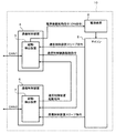
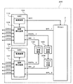
- FIG. 1 is a functional block diagram schematically showing an entire configuration of a vehicle control device according to a first embodiment. It is a timing chart which shows an example of an operation state of a vehicle control device concerning a 1st example.
- FIG. 1 is a functional block diagram schematically showing an overall configuration of a vehicle control device according to the present embodiment.
- a vehicle control device 10 includes a microcomputer (electronic control device) 2 that communicates with other electronic control devices (not shown) via a plurality of (for example, two) CAN communication paths (CAN1 and CAN2).
- Power supply device 3 capable of supplying or cutting off operation power to 2 and a plurality of CAN communication paths (CAN1 and CAN2) used for communication of the microcomputer 2; each CAN communication path (CAN1 and CAN1 of the microcomputer 2)
- the communication control devices 4 and 6 schematically control the communication related to CAN 2). Necessary power is supplied to the power supply 3 and the communication control devices 4 and 6 in the operating state and the standby state (sleep state) from a higher-level power supply device (not shown).
- the communication control device 4 controls communication in the CAN communication channel (CAN1) of the microcomputer 2, and the microcomputer 2 is another electronic device connected to the CAN communication channel (CAN1) via the communication control device 4 in the activated state. Communicate with the controller.
- the communication control device 4 is a control start command signal (wakeup frame) input to the communication control device 4 from the CAN communication channel (CAN 1), and a communication control device start input to the communication control device 4 from the communication control device 6 It has a start detection device 5 that detects a command signal (communication start command signal).
- the start detection device 5 functions as the state of the communication control device 4 when it detects the reception of the control start command signal instructing the start of the microcomputer 2 via the CAN communication path (CAN 1) in the standby state.
- Power supply start command signal (power supply start command signal) that instructs the power supply 3 to switch the supply state of the operation power to the microcomputer 2 from the interruption to the supply.
- a communication control device start command signal (communication start command signal) instructing another communication control device 6 to switch from the standby state to the operation state.
- the activation detection device 5 waits for the state of the communication control device 4 A state (sleep state) is switched to an operation state, and a power supply start command signal (power start command signal) instructing the power supply 3 to switch the supply state of the operation power to the microcomputer 2 from cutoff to supply is transmitted.
- a power supply start command signal power start command signal
- the start detection device 5 detects the communication control device standby command signal (communication standby command signal) from the microcomputer 2, it instructs the power supply device 3 to switch the supply state of the operating power to the microcomputer 2 from supply to cutoff.
- the power supply shutoff command signal (power shutoff command signal) is transmitted to shut off the supply of operating power from the power supply 3 to the microcomputer 2 and to switch the communication control unit 4 to the standby state.
- the power supply start command signal instructs supply of operating power from the power supply 3 to the microcomputer 2 by maintaining the signal level from OFF (Lo level) to ON (Hi level). doing.
- outputting the power supply shutoff command signal means maintaining the signal level of the power supply start command signal (power start command signal) from ON (Hi level) to OFF (Lo level). This is equivalent to the above, and instructs the power supply device 3 to switch the supply state of the operating power to the microcomputer 2 from the supply to the shutoff.
- the communication control device 6 controls communication in the CAN communication path (CAN 2) of the microcomputer 2, and the microcomputer 2 is another electronic device connected to the CAN communication path (CAN 2) via the communication control device 6 in the activated state. Communicate with the controller.
- the communication control device 6 is a control start command signal (wakeup frame) input from the CAN communication path (CAN 2) to the communication control device 6, and communication control device activation input from the communication control device 4 to the communication control device 6. It has a start detection device 7 that detects a command signal (communication start command signal).
- the communication control device 6 When the activation detection device 7 detects reception of a control activation command signal instructing activation of the microcomputer 2 in the standby state, the communication control device 6 is in the standby state (sleep state) whose function is limited. To the operation state, and outputs the communication control device start command signal (communication start command signal) to the communication control device 4. Further, when the activation detection device 7 detects a communication control device standby instruction signal (communication standby instruction signal) from the microcomputer 2, the activation detection device 7 switches the communication control device 6 to the standby state. The activation detection device 7 transmits a communication control device standby instruction signal (communication standby instruction signal) to the communication control device 4 to transmit a communication control device activation instruction signal (communication activation instruction) to the communication control device 6. The communication control device 6 is switched to the standby state by switching the level of the signal from ON (Hi level) to OFF (Lo level).
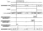
- FIG. 2 is a timing chart showing an example of the operation state of the vehicle control device according to the present embodiment.
- FIG. 2 exemplifies the operation state when the control start command signal is input to the communication control device 4.
- the communication control device 4 when the control start command signal (wakeup frame) is detected from the CAN communication channel (CAN1) in the communication control device 4, the communication control device 4 is started from the standby state (sleep state) (normal state) And outputs a power supply device start command signal (ON command signal) to the power supply device 3 and outputs a communication control start command signal to the communication control device 6.
- the microcomputer 2 shifts from the power-off state to the start-up state (normal state) after passing through the start-up preparation state, and the communication control device 6 switches from the standby state to the start-up state.
- the microcomputer 2 When the microcomputer 2 transitions from the start state to the standby state, the microcomputer 2 enters the end preparation state and outputs the communication control device standby instruction to the communication control device 6 to place the communication control device 6 in the standby state.
- the communication control device standby command is output to the communication control device 4 later than that, the communication control device 4 is put in the standby state, and the power supply device start command signal (ON command signal) is turned off (Lo level). Turn off the power.
- FIG. 11 is a functional block diagram schematically showing an overall configuration of a vehicle control device of a comparative example.
- FIG. 12 is a timing chart which shows an example of the operation state of the vehicle control apparatus of a comparative example.
- a wakeup frame by CAN communication (CAN1) is input to one communication control device 40.
- the activation detection device 50 outputs an activation instruction (ON instruction 1) to the power supply 3
- the microcomputer 2 activated by being supplied with power from the power supply 3 outputs an activation instruction to the communication control device 60 to perform communication control.
- the device 60 is activated. That is, it is necessary to wait for the start preparation of the microcomputer 2 from the start of the communication control device 40 having received the start signal by CAN communication to the start of the communication control device 60. As a result, the start of the communication control device 60 takes time There was a problem that
- the microcomputer 2 can communicate with other electronic control units via a plurality of CAN communication paths (CAN1, CAN2), and the operation power can be supplied to or shut off from the microcomputer 2 Power supply device 3 and communication control devices 4 and 6 provided in each of a plurality of CAN communication paths (CAN 1 and CAN 2) used for the communication of the microcomputer 2 and respectively controlling communication related to each communication path of the microcomputer 2
- the communication control device 4, which is one of the communication control devices 4 and 6, has received a control start command signal instructing to start the microcomputer 2 via the CAN communication path (CAN1) related to the communication control device 4.
- the state of the communication control device 4 is switched from the standby state in which the function is restricted to the operation state, and the power supply device 3 is switched from the interruption state to the supply state of the operation power to the microcomputer Communication start instruction signal for transmitting a power start instruction signal instructing the communication control device 6 and instructing another communication control device 6 different from the communication control device 4 among the plurality of communication control devices 4 and 6 to switch from the standby state to the operation state Since the signal is output, the communication control device 6 can be activated quickly without waiting for the activation completion of the microcomputer 2 to suppress an increase in activation time caused by an increase in the number of functional units involved in communication. it can.
- activation detection device 7 of communication control device 6 detects the ON (Hi state) and OFF (Lo state) of the level of the communication activation command signal
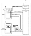
- the activation detection device 5 of the communication control device 4 sends a communication activation instruction to the activation detection device 7 of the communication control device 6 as in the modification shown in FIG. 3 and FIG.
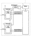
- the pulse generation circuit 8 may be provided on the communication path for transmitting the signal, and the pulse signal generated based on the communication activation command signal from the activation detection device 5 may be detected by the activation detection device 7.
- FIGS. 5 and 6 A first embodiment of the present invention will be described with reference to FIGS. 5 and 6. In this embodiment, only differences from the first embodiment will be described, and in the drawings used in this embodiment, the same members as those in the first embodiment are denoted by the same reference numerals, and the description will be omitted. .
- the present embodiment shows a configuration example using a plurality of (for example, two) system base chips (SBCs).
- SBCs system base chips
- FIG. 5 is a functional block diagram schematically showing the overall configuration of the vehicle control device according to the present embodiment.
- a vehicle control device 100 includes a microcomputer (electronic control device) 2 that communicates with other electronic control devices (not shown) via a plurality of (for example, eight) CAN communication paths (CAN1 to CAN8). It is roughly configured by a plurality of (for example, two) SBCs 104 and 106 that control communication related to each of two CAN communication paths (CAN 1 to CAN 8).
- the SBC 104 controls communication in the CAN communication path (CAN1 to CAN4) of the microcomputer 2, and the microcomputer 2 is another electronic control device connected to the CAN communication path (CAN1 to CAN4) via the SBC 104 in the activated state.
- Communicate with The SBC 104 detects activation for detecting a control activation instruction signal (wakeup frame) input to the SBC 104 from the CAN channel (CAN 1 to CAN 4) and a communication control apparatus activation instruction signal (WK_1) input from the SBC 106 to the SBC 104
- the apparatus 105 has a power supply 113 capable of supplying power to the SBC 104 and supplying or interrupting the operation power to the microcomputer 2.
- the activation detection device 105 detects the wakeup frame from any of the plurality of CAN communication paths (CAN1 to CAN4) or detects the rising edge of the communication control device activation command signal (after level conversion: WK_1) to detect the power supply device 113. And the communication control device start command signal (before level conversion: RSTN_1) is changed from the low level to the high level.
- the power supply device 113 starts power supply to the microcomputer 2 in response to an ON command from the start detection device 105.
- the SBC 106 controls communication in the CAN communication path (CAN 5 to CAN 8) of the microcomputer 2, and the microcomputer 2 is another electronic control device connected to the CAN communication path (CAN 5 to CAN 8) via the SBC 106 in the activated state.
- Communicate with The SBC 106 detects activation for detecting a control activation instruction signal (wakeup frame) input from the CAN channel (CAN 5 to CAN 8) to the SBC 106 and a communication control apparatus activation instruction signal (WK_2) input from the SBC 104 to the SBC 106
- a device 107 and a power supply device 123 for supplying power to the SBC 106 are included.
- the power supplies 113 and 123 are supplied with power necessary for the operation state and the standby state (sleep state) from a higher-level power supply device (not shown).
- the start detection device 107 detects a wakeup frame from any of a plurality of CAN communication paths (CAN5 to CAN8) or a power supply device 123 by detecting a rising edge of a communication control device start command signal (after level conversion: WK_2 signal). And the communication control apparatus start command signal (before level conversion: RSTN_2) is changed from the low level to the high level.
- the power supply device 123 starts power output according to the communication control device start command signal from the start detection device 105, but does not supply power to the microcomputer 2.
- level conversion circuits 130 and 140 for adjusting a signal voltage difference existing between the SBCs 104 and 106 are disposed.
- the level conversion circuits 130 and 140 are circuits for converting the signal level output from one of the SBCs 104 and 106 into a voltage value that can be input to the other. That is, level conversion circuit 130 converts the communication control apparatus start command signal (before level conversion: RSTN_2) output from SBC 106 into a communication control apparatus start command signal (after level conversion: WK_1) of voltage values that can be input to SBC 104. And input to the SBC 104.
- the level conversion circuit 140 converts the communication control apparatus start command signal (before level conversion: RSTN_1) output by the SBC 104 into a communication control apparatus start command signal (after level conversion: WK_2) of voltage values that can be input to the SBC 106. And input to the SBC 106.
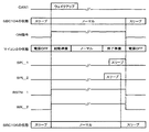
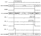
- FIG. 6 is a timing chart showing an example of the operation state of the vehicle control device according to the present example.
- the wakeup detection device 105 detects a wakeup frame on the CAN communication path (CAN1), and the state of the SBC 104 transitions from sleep to normal and wakes up. Immediately after waking up, the start detection device 105 outputs an ON command to the power supply 113, and the power supply 113 starts power supply to the microcomputer 2. Further, the activation detection device 105 changes the communication control device activation command signal (RSTN_1) from the low level to the high level together with the output of the ON command to the power supply device 113.
- RSTN_1 communication control device activation command signal
- the communication control device start command signal (RSTN_1) is level-converted to a voltage on the SBC 106 side by the level conversion circuit 140, and is input to the start detection device 107 as a communication control device start command signal (WK_2).
- WK_2 the communication control apparatus start command signal
- the state of the SBC 106 transitions from sleep to normal and wakes up.
- the microcomputer 2 whose power supply from the power supply device 113 is started is ready for activation, transits to the normal state, and the activation is completed.
- the SBC 106 can be started quickly without waiting for the completion of the start of the microcomputer 2, and an increase in the start time due to an increase in the number of functional units related to communication can be suppressed.
- FIG. 5 the configuration using two SBCs has been exemplified and described, but the number is not limited and the same configuration as the configuration using SBC more than the present embodiment is described. You may control.
- the present embodiment shows a configuration example in which the falling edge detection method is adopted for the start detection device 107 in the first embodiment.
- FIG. 7 is a functional block diagram schematically showing the overall configuration of the vehicle control device according to the present embodiment.
- FIG. 8 is a timing chart which shows an example of the operation
- the activation detection device 105 of the SBC 104 is on the communication path for transmitting a communication activation command signal to the activation detection device 107 of the SBC 106.
- the pulse generation circuit 8 is provided on the side, and the pulse signal (WK_2) generated by the pulse generation circuit 8 based on the signal obtained by converting the communication activation instruction signal (RSTN_1) from the activation detection device 105 by the level conversion circuit 140 It is configured to be detected at 107.
- the other configuration is the same as that of the first embodiment.
- the SBC 106 can be started quickly without waiting for the completion of the start of the microcomputer 2, and an increase in the start time due to an increase in the number of functional units related to communication can be suppressed.
- This embodiment shows a configuration example using a plurality of (for example, two) CAN transceivers.
- FIG. 9 is a functional block diagram schematically showing the overall configuration of the vehicle control device according to the present embodiment.
- a vehicle control device 300 includes a microcomputer (electronic control device) 2 that communicates with other electronic control devices (not shown) via a plurality of (for example, two) CAN communication paths (CAN1 and CAN2).
- the controller 303 is provided in each of a plurality of CAN communication paths (CAN1 and CAN2) used for communication of the microcomputer 2 with the regulator 303 capable of supplying or cutting off the operation power to 2 and each CAN communication path (CAN1 and CAN2) of the microcomputer 2 (2) CAN transceivers 304 and 306 that respectively control the communication involved in. Necessary power is supplied to the regulator 303 and the CAN transceivers 304 and 306 in the operating state and the standby state (sleep state) from a high-level power supply device (not shown).
- the CAN transceiver 304 controls communication in the CAN communication path (CAN1) of the microcomputer 2, and the microcomputer 2 is another electronic control device connected to the CAN communication path (CAN1) via the activated CAN transceiver 304.
- Communicate with The CAN transceiver 304 is a control start command signal (wakeup frame) input from the CAN communication path (CAN1) to the CAN transceiver 304, and a communication control unit start command signal (WK_1) input from the CAN transceiver 306 to the CAN transceiver 304. ) Is detected.
- the start detection device 305 detects a wakeup frame from the CAN communication channel (CAN1) or a rising edge of the communication control device start command signal (WK_1), the ON signal (REG_ON) to the regulator 303 and the CAN transceiver 306
- the signal (INH_1) which is commonly output as a communication control device activation command signal (WK_2), is changed from low level to high level to turn on the regulator 303 and activate the CAN transceiver 306.
- the regulator 303 starts power supply to the microcomputer 2 in response to an ON command from the start detection device 305.
- the CAN transceiver 306 controls communication in the CAN communication path (CAN2) of the microcomputer 2, and the microcomputer 2 is another electronic control device connected to the CAN communication path (CAN2) via the activated CAN transceiver 306.
- Communicate with The CAN transceiver 306 is a control start command signal (wakeup frame) input from the CAN communication path (CAN2) to the CAN transceiver 306, and a communication control unit start command signal (WK_2) input from the CAN transceiver 304 to the CAN transceiver 306. ) Is detected.
- start-up detection device 307 detects a wakeup frame from CAN communication path (CAN2) or detects a rising edge of communication control device start-up command signal (WK_2)
- communication control device start-up command signal (WK_1) to CAN transceiver 304 Changes the signal (INH_2) output as) from low level to high level to activate the CAN transceiver 304.
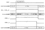
- FIG. 10 is a timing chart showing an example of the operation state of the vehicle control device according to the present example.
- the wakeup detection device 305 detects a wakeup frame on the CAN communication path (CAN1), and the state of the CAN transceiver 304 transitions from sleep to normal and wakes up.
- the start detection unit 305 changes the signal (INH_1) from low level to high level to turn on (start) the regulator 303, and the regulator 303 starts power supply to the microcomputer 2.
- the signal (INH_1) signal is input to the activation detection device 307 as a communication control device activation command signal (WK_2) of the CAN transceiver 306, and the state of the CAN transceiver 306 transitions from sleep to normal and wakes up.
- the microcomputer 2 whose power supply from the regulator 303 is started transitions to the normal state through preparation for starting, and the starting is completed.
- the same effects as those of the embodiment of the present invention can be obtained. That is, in the present embodiment, the CAN transceiver 306 can be started quickly without waiting for the completion of the start of the microcomputer 2, and an increase in the start time due to an increase in the number of functional units involved in communication can be suppressed.
- FIG. 9 the configuration using two CAN transceivers has been exemplified and described, but the number is not limited, and a configuration using more CAN transceivers than this embodiment is used. Similar control may be performed.
- the present invention is not limited to the above-described embodiments, and includes various modifications.
- the embodiment described above is described in detail in order to explain the present invention in an easy-to-understand manner, and is not necessarily limited to one having all the described configurations.
- each of the configurations, functions, and the like described above may be realized by designing a part or all of them with, for example, an integrated circuit.
- each configuration, function, etc. described above may be realized by software by the processor interpreting and executing a program that realizes each function.
Landscapes
- Engineering & Computer Science (AREA)
- Theoretical Computer Science (AREA)
- General Engineering & Computer Science (AREA)
- Software Systems (AREA)
- Physics & Mathematics (AREA)
- General Physics & Mathematics (AREA)
- Computer Hardware Design (AREA)
- Computer Security & Cryptography (AREA)
- Mechanical Engineering (AREA)
- Small-Scale Networks (AREA)
- Power Sources (AREA)
- Stored Programmes (AREA)
- Selective Calling Equipment (AREA)
Abstract
通信に係る機能部の増加に伴う起動時間の増加を抑制することができる車両制御装置を提供する。CAN通信路(CAN1,CAN2)を介して他の電子制御装置と通信を行うマイコン(2)への動作電力の供給又は遮断が可能な電源装置(3)と、マイコン(2)の通信に用いられる複数のCAN通信路(CAN1,CAN2)のそれぞれに設けられた通信制御装置(4,6)とを備え、通信制御装置(4)は通信制御装置(4)に関わるCAN通信路(CAN1)を介してマイコン(2)を起動することを指示する制御起動指令信号を受信した場合に、通信制御装置(4)の状態を機能が制限された待機状態から動作状態に切り換え、電源装置(3)にマイコン(2)への動作電力の供給状態を遮断から供給に切り換えるように指示する電源起動指令信号を送信するとともに、通信制御装置(6)に待機状態から動作状態に切り換えることを指示する通信起動指令信号を出力する。
Description
本発明は、車両を制御する車両制御装置に関する。
車両には複数の電子制御装置(以下、ECUと称する)が搭載されており、車両内の様々な場所に設置されている。これら複数のECUは、各々が協調して、一つのアプリケーションを実現する。そのため、各ECUは通信線で接続されてネットワークを構成し、各ECU間でのデータ通信を行っている。これらのECUは車両内の様々な場所に設置されていることから、設置場所毎に構成された異なるネットワーク間の通信を車載ゲートウェイ装置で中継することにより、一つの車載ネットワークを構成している。車載ネットワークの通信プロトコルとして、主にCANが広く利用されている。
また、近年は車載ゲートウェイ装置、及び、ECUにおけるCANのチャネル数が増加してきており、電源と一つ以上のCANトランシーバをワンチップにしたシステムベースチップ(SBC:System Base Chip)を使用した構成や、CANのチャネル数が一つのSBCでは不足する場合に不足するチャネル数分のCANトランシーバを追加する等の構成が用いられている。
このように、一つ以上のCANインタフェースを具備する技術としては、例えば、特許文献1に記載のものが知られている。特許文献1には、他の制御ユニットと通信バスを介して通信する電子制御装置であって、送信線と受信線を介して互いに接続された通信制御部とトランシーバと、前記電子制御装置が、通常の動作状態である通常モードよりも消費電力の少ない動作状態であるスリープモードで動作時に、前記トランシーバが受信した受信信号をウエイクアップデータとして記憶する記憶部と、を備え、前記トランシーバは、前記通信制御部から前記送信線を介して入力される送信信号を前記通信バスに送出するとともに、前記通信バスから受信した受信信号を、前記受信線を介して前記通信制御部へ出力し、前記通信制御部は、前記トランシーバから前記ウエイクアップデータを受信したときに、前記スリープモードから前記通常モードへの遷移を開始し、前記通常モードに遷移した後に、前記記憶部から前記ウエイクアップデータを取得し、前記ウエイクアップデータが適正なものか否かを判定することが開示されている。
しかしながら、上記従来技術のようにSBCやCANトランシーバなどのCAN通信を担う制御機能部を複数組み合わせた構成において、例えば、1つの制御機能部にCAN通信によるウェイクアップフレームが入力された場合には、起動検出部が電源部に起動指令を出力し、電源部から電源供給されて起動したマイコンが他の制御機能部に起動指令を出力し、他の制御部が起動する。すなわち、CAN通信による起動信号を受信した制御機能部の起動から他の制御機能部の起動までには、マイコンの起動準備を待つ必要があり、結果として他の制御機能部の起動に時間がかかってしまうという課題があった。
本発明は上記に鑑みてなされたものであり、通信に係る機能部の増加に伴う起動時間の増加を抑制することができる車両制御装置を提供することを目的とする。
上記目的を達成するために、本発明は、複数の通信路を介して他の電子制御装置と通信を行う電子制御装置と、前記電子制御装置への動作電力の供給又は遮断が可能な電源装置と、前記電子制御装置の通信に用いられる複数の通信路のそれぞれに設けられ、前記電子制御装置の各通信路に関わる通信をそれぞれ制御する複数の通信制御装置とを備え、前記複数の通信制御装置の1つである第一通信制御装置は、該第一通信制御装置に関わる通信路を介して前記電子制御装置を起動することを指示する制御起動指令信号を受信した場合に、前記第一通信制御装置の状態を機能が制限された待機状態から動作状態に切り換え、前記電源装置に前記電子制御装置への動作電力の供給状態を遮断から供給に切り換えるように指示する電源起動指令信号を送信するとともに、前記複数の通信制御装置のうち前記第一通信制御装置とは異なる他の通信制御装置に待機状態から動作状態に切り換えることを指示する通信起動指令信号を出力するものとする。
本発明によれば、通信型追従走行の安定性をより向上することができる。
<第1の実施の形態>
以下、本発明の第1の実施の形態を図面を参照しつつ説明する。
以下、本発明の第1の実施の形態を図面を参照しつつ説明する。
図1は、本実施の形態に係る車両制御装置の全体構成を概略的に示す機能ブロック図である。
図1において、車両制御装置10は、複数(例えば、2つ)のCAN通信路(CAN1,CAN2)を介して図示しない他の電子制御装置と通信を行うマイコン(電子制御装置)2と、マイコン2への動作電力の供給又は遮断が可能な電源装置3と、マイコン2の通信に用いられる複数のCAN通信路(CAN1,CAN2)のそれぞれに設けられ、マイコン2の各CAN通信路(CAN1,CAN2)に関わる通信をそれぞれ制御する複数(例えば、2つ)の通信制御装置4,6とから概略構成されている。なお、電源装置3及び通信制御装置4,6には、図示しない上位の電源装置から動作状態や待機状態(スリープ状態)で必要な電力が供給されている。
通信制御装置4は、マイコン2のCAN通信路(CAN1)における通信を制御するものであり、マイコン2は起動状態の通信制御装置4を介してCAN通信路(CAN1)に接続される他の電子制御装置と通信を行う。通信制御装置4は、CAN通信路(CAN1)から通信制御装置4に入力される制御起動指令信号(ウェイクアップフレーム)、及び、通信制御装置6から通信制御装置4に入力される通信制御装置起動指令信号(通信起動指令信号)を検出する起動検出装置5を有している。
起動検出装置5は、待機状態において、CAN通信路(CAN1)を介して、マイコン2を起動することを指示する制御起動指令信号の受信を検出した場合には、通信制御装置4の状態を機能が制限された待機状態(スリープ状態)から動作状態に切り換え、電源装置3にマイコン2への動作電力の供給状態を遮断から供給に切り換えるように指示する電源装置起動指令信号(電源起動指令信号)を送信するとともに、他の通信制御装置6に待機状態から動作状態に切り換えることを指示する通信制御装置起動指令信号(通信起動指令信号)を出力する。
また、起動検出装置5は、待機状態において、通信制御装置6の起動検出装置7から通信制御装置起動指令信号(通信起動指令信号)が入力された場合には、通信制御装置4の状態を待機状態(スリープ状態)から動作状態に切り換え、電源装置3にマイコン2への動作電力の供給状態を遮断から供給に切り換えるように指示する電源装置起動指令信号(電源起動指令信号)を送信する。
また、起動検出装置5は、マイコン2からの通信制御装置待機指令信号(通信待機指令信号)を検出すると、電源装置3にマイコン2への動作電力の供給状態を供給から遮断に切り換えるように指示する電源装置遮断指令信号(電源遮断指令信号)を送信して電源装置3からマイコン2への動作電力の供給を遮断するとともに、通信制御装置4を待機状態に切り換える。なお、電源装置起動指令信号(電源起動指令信号)は、信号レベルをOFF(Loレベル)からON(Hiレベル)にして維持することで、電源装置3からマイコン2への動作電力の供給を指示している。なお、電源装置遮断指令信号(電源遮断指令信号)を出力するということは、電源装置起動指令信号(電源起動指令信号)の信号レベルをON(Hiレベル)からOFF(Loレベル)にして維持することと同義であり、これによって電源装置3にマイコン2への動作電力の供給状態を供給から遮断に切り換えるように指示する。
通信制御装置6は、マイコン2のCAN通信路(CAN2)における通信を制御するものであり、マイコン2は起動状態の通信制御装置6を介してCAN通信路(CAN2)に接続される他の電子制御装置と通信を行う。通信制御装置6は、CAN通信路(CAN2)から通信制御装置6に入力される制御起動指令信号(ウェイクアップフレーム)、及び、通信制御装置4から通信制御装置6に入力される通信制御装置起動指令信号(通信起動指令信号)を検出する起動検出装置7を有している。
起動検出装置7は、待機状態において、マイコン2を起動することを指示する制御起動指令信号の受信を検出した場合には、通信制御装置6の状態を機能が制限された待機状態(スリープ状態)から動作状態に切り換え、通信制御装置4に通信制御装置起動指令信号(通信起動指令信号)を出力する。また、起動検出装置7は、マイコン2からの通信制御装置待機指令信号(通信待機指令信号)を検出すると、通信制御装置6を待機状態に切り換える。なお、起動検出装置7は、通信制御装置4に通信制御装置待機指令信号(通信待機指令信号)を送信することにより、通信制御装置6に出力されている通信制御装置起動指令信号(通信起動指令信号)のレベルをON(Hiレベル)からOFF(Loレベル)に切り換えることによって、通信制御装置6を待機状態に切り換える。
図2は、本実施の形態に係る車両制御装置の動作状態の一例を示すタイミングチャートである。図2では、通信制御装置4に制御起動指令信号が入力された場合の動作状態を例示している。
図2に示すように、通信制御装置4においてCAN通信路(CAN1)から制御起動指令信号(ウェイクアップフレーム)が検知されると、通信制御装置4は待機状態(スリープ状態)から起動状態(ノーマル状態)に切り換わり、電源装置起動指令信号(ON指令信号)を電源装置3に出力するとともに、通信制御装置6に通信制御起動指令信号を出力する。これにより、マイコン2は電源OFF状態から起動準備状態を経て起動状態(ノーマル状態)に移行し、通信制御装置6は待機状態から起動状態に切り換わる。また、マイコン2が起動状態から待機状態に遷移する場合、マイコン2は終了準備状態に入るとともに、通信制御装置6に通信制御装置待機指令を出力して通信制御装置6を待機状態としつつ、それよりも遅れて通信制御装置4に通信制御装置待機指令を出力して通信制御装置4を待機状態とし、電源装置起動指令信号(ON指令信号)をOFF(Loレベル)にすることでマイコン2の電源をOFFする。
以上のように構成した本実施の形態の作用効果を比較例としての従来技術と対比して説明する。
図11は、比較例の車両制御装置の全体構成を概略的に示す機能ブロック図である。また、図12は、比較例の車両制御装置の動作状態の一例を示すタイミングチャートである。
図11及び図12に示す比較例としての従来技術のように、通信制御装置40を複数組み合わせた構成において、例えば、1つの通信制御装置40にCAN通信(CAN1)によるウェイクアップフレームが入力された場合には、起動検出装置50が電源装置3に起動指令(ON指令1)を出力し、電源装置3から電源供給されて起動したマイコン2が通信制御装置60に起動指令を出力して通信制御装置60が起動する。すなわち、CAN通信による起動信号を受信した通信制御装置40の起動から通信制御装置60の起動までには、マイコン2の起動準備を待つ必要があり、結果として通信制御装置60の起動に時間がかかってしまうという課題があった。
これに対して、本実施の形態においては、複数のCAN通信路(CAN1,CAN2)を介して他の電子制御装置と通信を行うマイコン2と、マイコン2への動作電力の供給又は遮断が可能な電源装置3と、マイコン2の通信に用いられる複数のCAN通信路(CAN1,CAN2)のそれぞれに設けられ、マイコン2の各通信路に関わる通信をそれぞれ制御する通信制御装置4,6とを備え、通信制御装置4,6の1つである通信制御装置4は、通信制御装置4に関わるCAN通信路(CAN1)を介してマイコン2を起動することを指示する制御起動指令信号を受信した場合に、通信制御装置4の状態を機能が制限された待機状態から動作状態に切り換え、電源装置3にマイコン2への動作電力の供給状態を遮断から供給に切り換えるように指示する電源起動指令信号を送信するとともに、複数の通信制御装置4,6のうち通信制御装置4とは異なる他の通信制御装置6に待機状態から動作状態に切り換えることを指示する通信起動指令信号を出力するように構成したので、通信制御装置6の起動をマイコン2の起動完了を待たずに早く行うことができ、通信に係る機能部の増加に伴う起動時間の増加を抑制することができる。
なお、本実施の形態においては、通信制御装置6の起動検出装置7が通信起動指令信号のレベルのON(Hi状態)およびOFF(Lo状態)を検知する場合を例示して説明したが、起動検出装置7が立ち下がりエッジ検出方式の場合には、図3及び図4に示す変形例のように、通信制御装置4の起動検出装置5から通信制御装置6の起動検出装置7に通信起動指令信号を送る通信経路上にパルス生成回路8を設け、起動検出装置5からの通信起動指令信号に基づいて生成したパルス信号が起動検出装置7で検出されるように構成してもよい。
<第1の実施例>
本発明の第1の実施例を図5及び図6を参照しつつ説明する。本実施例では第1の実施の形態との相違点についてのみ説明するものとし、本実施例で用いる図面において第1の実施の形態と同様の部材には同じ符号を付し、説明を省略する。
本発明の第1の実施例を図5及び図6を参照しつつ説明する。本実施例では第1の実施の形態との相違点についてのみ説明するものとし、本実施例で用いる図面において第1の実施の形態と同様の部材には同じ符号を付し、説明を省略する。
本実施例は、複数(例えば、2つ)のシステムベースチップ(SBC:System Base Chip)を使用した構成例を示すものである。
図5は、本実施例に係る車両制御装置の全体構成を概略的に示す機能ブロック図である。
図5において、車両制御装置100は、複数(例えば、8つ)のCAN通信路(CAN1~CAN8)を介して図示しない他の電子制御装置と通信を行うマイコン(電子制御装置)2と、マイコン2の各CAN通信路(CAN1~CAN8)に関わる通信を制御する複数(例えば、2つ)のSBC104,106とから概略構成されている。
SBC104は、マイコン2のCAN通信路(CAN1~CAN4)における通信を制御するものであり、マイコン2は起動状態のSBC104を介してCAN通信路(CAN1~CAN4)に接続される他の電子制御装置と通信を行う。SBC104は、CAN通信路(CAN1~CAN4)からSBC104に入力される制御起動指令信号(ウェイクアップフレーム)、及び、SBC106からSBC104に入力される通信制御装置起動指令信号(WK_1)を検出する起動検出装置105と、SBC104に電力を供給するとともに、マイコン2への動作電力の供給又は遮断が可能な電源装置113とを有している。
起動検出装置105は、複数のCAN通信路(CAN1~CAN4)のいずれかからのウェイクアップフレームの検出、又は、通信制御装置起動指令信号(レベル変換後:WK_1)の立ち上がりエッジ検出によって電源装置113にON信号を出力するとともに、通信制御装置起動指令信号(レベル変換前:RSTN_1)をロウレベルからハイレベルへ変化させる。電源装置113は起動検出装置105からのON指令によってマイコン2へ電源供給を開始する。
SBC106は、マイコン2のCAN通信路(CAN5~CAN8)における通信を制御するものであり、マイコン2は起動状態のSBC106を介してCAN通信路(CAN5~CAN8)に接続される他の電子制御装置と通信を行う。SBC106は、CAN通信路(CAN5~CAN8)からSBC106に入力される制御起動指令信号(ウェイクアップフレーム)、及び、SBC104からSBC106に入力される通信制御装置起動指令信号(WK_2)を検出する起動検出装置107と、SBC106に電力を供給する電源装置123とを有している。
なお、電源装置113,123には、図示しない上位の電源装置から動作状態や待機状態(スリープ状態)で必要な電力が供給されている。
起動検出装置107は、複数のCAN通信路(CAN5~CAN8)のいずれかからのウェイクアップフレーム検出、もしくは、通信制御装置起動指令信号(レベル変換後:WK_2信号)の立ち上がりエッジ検出によって電源装置123にON信号を出力するとともに、通信制御装置起動指令信号(レベル変換前:RSTN_2)をロウレベルからハイレベルへ変化させる。電源装置123は起動検出装置105からの通信制御装置起動指令信号によって電源出力を開始するが、マイコン2への電源供給はしない。
起動検出装置105と起動検出装置107間における通信制御装置起動指令信号の通信路には、SBC104,106間に存在する信号電圧差を調整するレベル変換回路130,140が配置されている。レベル変換回路130,140は、SBC104,106の一方から出力された信号レベルを他方の入力可能な電圧値に変換する回路である。すなわち、レベル変換回路130は、SBC106が出力する通信制御装置起動指令信号(レベル変換前:RSTN_2)をSBC104に入力可能な電圧値の通信制御装置起動指令信号(レベル変換後:WK_1)に変換して、SBC104に入力する。同様に、レベル変換回路140は、SBC104が出力する通信制御装置起動指令信号(レベル変換前:RSTN_1)をSBC106に入力可能な電圧値の通信制御装置起動指令信号(レベル変換後:WK_2)に変換して、SBC106に入力する。
図6は、本実例に係る車両制御装置の動作状態の一例を示すタイミングチャートである。
図6に示すように、CAN通信路(CAN1)上のウェイクアップフレームを起動検出装置105が検出し、SBC104の状態がスリープからノーマルへ遷移してウェイクアップする。ウェイクアップすると直ちに起動検出装置105は電源装置113へON指令を出力し、電源装置113はマイコン2へ電源供給を開始する。また、起動検出装置105は、電源装置113へのON指令の出力とともに、通信制御装置起動指令信号(RSTN_1)をロウレベルからハイレベルへ変化させる。通信制御装置起動指令信号(RSTN_1)は、レベル変換回路140によってSBC106側の電圧にレベル変換され、通信制御装置起動指令信号(WK_2)として起動検出装置107へ入力される。通信制御装置起動指令信号(WK_2)がSBC106へ入力されると、SBC106の状態がスリープからノーマルへ遷移してウェイクアップする。一方、電源装置113からの電源供給が開始されたマイコン2は起動準備を経てノーマル状態へ遷移し、起動完了となる。
以上のように構成した本実施例においても、本発明の実施の形態と同様の効果を得ることができる。すなわち、本実施例においては、SBC106の起動をマイコン2の起動完了を待たずに早く行うことができ、通信に係る機能部の増加に伴う起動時間の増加を抑制することができる。
なお、本実施例(図5)においては、2つのSBCを使用した構成を例示して説明したが、その数を限定するものではなく、本実施例よりも多いSBCを用いた構成として同様の制御を行っても良い。
<第2の実施例>
本発明の第2の実施例を図7及び図8を参照しつつ説明する。本実施例では第1の実施例との相違点についてのみ説明するものとし、本実施例で用いる図面において第1の実施例と同様の部材には同じ符号を付し、説明を省略する。
本発明の第2の実施例を図7及び図8を参照しつつ説明する。本実施例では第1の実施例との相違点についてのみ説明するものとし、本実施例で用いる図面において第1の実施例と同様の部材には同じ符号を付し、説明を省略する。
本実施例は、第1の実施例において、起動検出装置107に立ち下がりエッジ検出方式を採用した構成例を示すものである。
図7は、本実施例に係る車両制御装置の全体構成を概略的に示す機能ブロック図である。また、図8は、本実例に係る車両制御装置の動作状態の一例を示すタイミングチャートである。
図7に示すように、本実施例の車両制御装置200では、SBC104の起動検出装置105からSBC106の起動検出装置107に通信起動指令信号を送る通信経路上であって、レベル変換回路140の下流側にパルス生成回路8を設け、起動検出装置105からの通信起動指令信号(RSTN_1)をレベル変換回路140で変換した信号に基づいてパルス生成回路8で生成したパルス信号(WK_2)が起動検出装置107で検出されるように構成している。
その他の構成は第1の実施例と同様である。
以上のように構成した本実施例においても、第1の実施例と同様の効果を得ることができる。すなわち、本実施例においては、SBC106の起動をマイコン2の起動完了を待たずに早く行うことができ、通信に係る機能部の増加に伴う起動時間の増加を抑制することができる。
<第3の実施例>
本発明の第3の実施例を図9及び図10を参照しつつ説明する。本実施例では第1の実施の形態との相違点についてのみ説明するものとし、本実施例で用いる図面において第1の実施の形態と同様の部材には同じ符号を付し、説明を省略する。
本発明の第3の実施例を図9及び図10を参照しつつ説明する。本実施例では第1の実施の形態との相違点についてのみ説明するものとし、本実施例で用いる図面において第1の実施の形態と同様の部材には同じ符号を付し、説明を省略する。
本実施例は、複数(例えば、2つ)のCANトランシーバを使用した構成例を示すものである。
図9は、本実施例に係る車両制御装置の全体構成を概略的に示す機能ブロック図である。
図9において、車両制御装置300は、複数(例えば、2つ)のCAN通信路(CAN1,CAN2)を介して図示しない他の電子制御装置と通信を行うマイコン(電子制御装置)2と、マイコン2への動作電力の供給又は遮断が可能なレギュレータ303と、マイコン2の通信に用いられる複数のCAN通信路(CAN1,CAN2)のそれぞれに設けられ、マイコン2の各CAN通信路(CAN1,CAN2)に関わる通信をそれぞれ制御する複数(例えば、2つ)のCANトランシーバ304,306とから概略構成されている。なお、レギュレータ303及びCANトランシーバ304,306には、図示しない上位の電源装置から動作状態や待機状態(スリープ状態)で必要な電力が供給されている。
CANトランシーバ304は、マイコン2のCAN通信路(CAN1)における通信を制御するものであり、マイコン2は起動状態のCANトランシーバ304を介してCAN通信路(CAN1)に接続される他の電子制御装置と通信を行う。CANトランシーバ304は、CAN通信路(CAN1)からCANトランシーバ304に入力される制御起動指令信号(ウェイクアップフレーム)、及び、CANトランシーバ306からCANトランシーバ304に入力される通信制御装置起動指令信号(WK_1)を検出する起動検出装置305を有している。
起動検出装置305は、CAN通信路(CAN1)からのウェイクアップフレーム検出、又は、通信制御装置起動指令信号(WK_1)の立ち上がりエッジを検出すると、レギュレータ303へのON信号(REG_ON)及びCANトランシーバ306への通信制御装置起動指令信号(WK_2)として共通に出力される信号(INH_1)をロウレベルからハイレベルへ変化させてレギュレータ303をONするとともに、CANトランシーバ306を起動させる。レギュレータ303は起動検出装置305からのON指令によってマイコン2へ電源供給を開始する。
CANトランシーバ306は、マイコン2のCAN通信路(CAN2)における通信を制御するものであり、マイコン2は起動状態のCANトランシーバ306を介してCAN通信路(CAN2)に接続される他の電子制御装置と通信を行う。CANトランシーバ306は、CAN通信路(CAN2)からCANトランシーバ306に入力される制御起動指令信号(ウェイクアップフレーム)、及び、CANトランシーバ304からCANトランシーバ306に入力される通信制御装置起動指令信号(WK_2)を検出する起動検出装置307を有している。
起動検出装置307は、CAN通信路(CAN2)からのウェイクアップフレーム検出、又は、通信制御装置起動指令信号(WK_2)の立ち上がりエッジを検出すると、CANトランシーバ304への通信制御装置起動指令信号(WK_1)として出力される信号(INH_2)をロウレベルからハイレベルへ変化させてCANトランシーバ304を起動させる。
図10は、本実例に係る車両制御装置の動作状態の一例を示すタイミングチャートである。
図10に示すように、CAN通信路(CAN1)上のウェイクアップフレームを起動検出装置305が検出し、CANトランシーバ304の状態がスリープからノーマルへ遷移してウェイクアップする。ウェイクアップすると直ちに起動検出装置305は信号(INH_1)をロウレベルからハイレベルへ変化させて、レギュレータ303をON(起動)し、レギュレータ303はマイコン2へ電源供給を開始する。また、信号(INH_1)信号はCANトランシーバ306の通信制御装置起動指令信号(WK_2)として起動検出装置307へ入力され、CANトランシーバ306の状態がスリープからノーマルへ遷移してウェイクアップする。一方、レギュレータ303からの電源供給が開始されたマイコン2は起動準備を経てノーマル状態へ遷移し、起動完了となる。
以上のように構成した本実施例においても、本発明の実施の形態と同様の効果を得ることができる。すなわち、本実施例においては、CANトランシーバ306の起動をマイコン2の起動完了を待たずに早く行うことができ、通信に係る機能部の増加に伴う起動時間の増加を抑制することができる。
なお、本実施例(図9)においては、2つのCANトランシーバを使用した構成を例示して説明したが、その数を限定するものではなく、本実施例よりも多いCANトランシーバを用いた構成として同様の制御を行っても良い。
<付記>
なお、本発明は上記した各実施の形態に限定されるものではなく、様々な変形例が含まれる。例えば、上記した実施の形態は本願発明を分かりやすく説明するために詳細に説明したものであり、必ずしも説明した全ての構成を備えるものに限定されるものではない。また、上記の各構成、機能等は、それらの一部又は全部を、例えば集積回路で設計する等により実現してもよい。また、上記の各構成、機能等は、プロセッサがそれぞれの機能を実現するプログラムを解釈し、実行することによりソフトウェアで実現してもよい。
なお、本発明は上記した各実施の形態に限定されるものではなく、様々な変形例が含まれる。例えば、上記した実施の形態は本願発明を分かりやすく説明するために詳細に説明したものであり、必ずしも説明した全ての構成を備えるものに限定されるものではない。また、上記の各構成、機能等は、それらの一部又は全部を、例えば集積回路で設計する等により実現してもよい。また、上記の各構成、機能等は、プロセッサがそれぞれの機能を実現するプログラムを解釈し、実行することによりソフトウェアで実現してもよい。
1,10,20,100,200,300…車両制御装置、2…マイコン(電子制御装置)、2…マイコン、3…電源装置、4,6,40,60…通信制御装置、5,7,50,70,105,107,305,307…起動検出装置、8…パルス生成回路、113,123…電源装置、130,140…レベル変換回路、303…レギュレータ、304,306…CANトランシーバ
Claims (3)
- 複数の通信路を介して他の電子制御装置と通信を行う電子制御装置と、
前記電子制御装置への動作電力の供給又は遮断が可能な電源装置と、
前記電子制御装置の通信に用いられる複数の通信路のそれぞれに設けられ、前記電子制御装置の各通信路に関わる通信をそれぞれ制御する複数の通信制御装置とを備え、
前記複数の通信制御装置の1つである第一通信制御装置は、該第一通信制御装置に関わる通信路を介して前記電子制御装置を起動することを指示する制御起動指令信号を受信した場合に、前記第一通信制御装置の状態を機能が制限された待機状態から動作状態に切り換え、前記電源装置に前記電子制御装置への動作電力の供給状態を遮断から供給に切り換えるように指示する電源起動指令信号を送信するとともに、前記複数の通信制御装置のうち前記第一通信制御装置とは異なる他の通信制御装置に待機状態から動作状態に切り換えることを指示する通信起動指令信号を出力することを特徴とする車両制御装置。 - 請求項1記載の車両制御装置において、
前記第一通信制御装置とは異なる他の通信制御装置の1つである第二通信制御装置は、該第二通信制御装置に関わる通信路を介して制御起動指令信号を受信した場合に、前記第二通信制御装置の状態を待機状態から動作状態に切り換えるとともに、前記第一通信制御装置に通信起動指令信号を送信し、
前記第一通信制御装置は、受信した通信起動指令信号に基づいて、前記第一通信制御装置の状態を待機状態から動作状態に切り換えるとともに、前記電源装置に電源起動指令信号を送信することを特徴とする車両制御装置。 - 請求項1記載の車両制御装置において、
前記第一通信制御装置から前記電源装置に送信する電源起動指令信号と前記他の通信制御装置に送信する通信起動指令信号は共通であることを特徴とする車両制御装置。
Priority Applications (4)
| Application Number | Priority Date | Filing Date | Title |
|---|---|---|---|
| JP2019525616A JP6872016B2 (ja) | 2017-06-22 | 2018-06-19 | 車両制御装置 |
| DE112018002033.9T DE112018002033T5 (de) | 2017-06-22 | 2018-06-19 | Fahrzeugsteuereinrichtung |
| CN201880031961.5A CN110785327B (zh) | 2017-06-22 | 2018-06-19 | 车辆控制装置 |
| US16/612,666 US11472354B2 (en) | 2017-06-22 | 2018-06-19 | Vehicle controller |
Applications Claiming Priority (2)
| Application Number | Priority Date | Filing Date | Title |
|---|---|---|---|
| JP2017-122602 | 2017-06-22 | ||
| JP2017122602 | 2017-06-22 |
Publications (1)
| Publication Number | Publication Date |
|---|---|
| WO2018235790A1 true WO2018235790A1 (ja) | 2018-12-27 |
Family
ID=64737116
Family Applications (1)
| Application Number | Title | Priority Date | Filing Date |
|---|---|---|---|
| PCT/JP2018/023193 Ceased WO2018235790A1 (ja) | 2017-06-22 | 2018-06-19 | 車両制御装置 |
Country Status (5)
| Country | Link |
|---|---|
| US (1) | US11472354B2 (ja) |
| JP (1) | JP6872016B2 (ja) |
| CN (1) | CN110785327B (ja) |
| DE (1) | DE112018002033T5 (ja) |
| WO (1) | WO2018235790A1 (ja) |
Cited By (3)
| Publication number | Priority date | Publication date | Assignee | Title |
|---|---|---|---|---|
| CN111546999A (zh) * | 2020-04-22 | 2020-08-18 | 深圳市元征科技股份有限公司 | 汽车点火及熄火的双检测电路、方法及系统 |
| JP2021048477A (ja) * | 2019-09-18 | 2021-03-25 | 株式会社デンソー | 車両用ネットワークシステム |
| CN115923691A (zh) * | 2022-11-28 | 2023-04-07 | 合众新能源汽车股份有限公司 | 一种车机系统的电源状态管理系统 |
Families Citing this family (7)
| Publication number | Priority date | Publication date | Assignee | Title |
|---|---|---|---|---|
| US11491930B2 (en) * | 2019-12-03 | 2022-11-08 | Woodward, Inc. | Systems and methods for commanded or uncommanded channel switchover in a multiple processor controller |
| CN111619473B (zh) * | 2020-05-29 | 2023-04-25 | 重庆长安汽车股份有限公司 | 一种汽车静态电源管理系统及管理方法 |
| JP7472767B2 (ja) * | 2020-12-03 | 2024-04-23 | 株式会社デンソー | ネットワークシステム |
| CN114859792B (zh) * | 2022-05-20 | 2025-06-13 | 东软睿驰汽车技术(沈阳)有限公司 | 一种can唤醒源的识别系统及方法 |
| CN119705322A (zh) * | 2023-09-27 | 2025-03-28 | 株式会社电装 | 通信系统以及供电切换装置 |
| US20250103118A1 (en) * | 2023-09-27 | 2025-03-27 | Denso Corporation | Communication system, electronic control device and management device |
| JP7865317B2 (ja) * | 2023-11-13 | 2026-05-26 | トヨタ自動車株式会社 | 管理装置、制御プログラム、及び制御方法 |
Citations (3)
| Publication number | Priority date | Publication date | Assignee | Title |
|---|---|---|---|---|
| JP2014165746A (ja) * | 2013-02-26 | 2014-09-08 | Denso Corp | データ中継装置 |
| JP2016048848A (ja) * | 2014-08-27 | 2016-04-07 | 株式会社デンソー | 中継装置 |
| JP2017061166A (ja) * | 2015-09-22 | 2017-03-30 | 株式会社デンソー | 電子制御装置 |
Family Cites Families (13)
| Publication number | Priority date | Publication date | Assignee | Title |
|---|---|---|---|---|
| JP2768520B2 (ja) * | 1989-02-17 | 1998-06-25 | ローベルト ボツシユ ゲゼルシヤフト ミツト ベシユレンクテル ハフツング | ネツトワークインターフエース |
| US6070539A (en) * | 1997-03-21 | 2000-06-06 | Case Corporation | Variable rate agricultural product application implement with multiple inputs and feedback |
| US20030230443A1 (en) * | 2002-01-08 | 2003-12-18 | David Cramer | Advanced composite hybrid-electric vehicle |
| US6747498B1 (en) * | 2002-12-20 | 2004-06-08 | Texas Instruments Incorporated | CAN receiver wake-up circuit |
| JP2005086692A (ja) * | 2003-09-10 | 2005-03-31 | Calsonic Kansei Corp | ゲートウェイ装置 |
| US7289830B2 (en) * | 2005-03-18 | 2007-10-30 | Lear Corporation | System and method for vehicle module wake up in response to communication activity |
| JP2007122108A (ja) * | 2005-10-25 | 2007-05-17 | Hitachi Ltd | セルフチェック機能を有するディスクドライブ装置を用いたストレージシステムの制御 |
| US20100036546A1 (en) * | 2008-08-07 | 2010-02-11 | Patriot Lift Co., Llc | Security apparatus for pneumatically operated devices mounted on a vehicle |
| JP2015158828A (ja) * | 2014-02-25 | 2015-09-03 | シャープ株式会社 | 電子黒板装置 |
| JP2015199444A (ja) * | 2014-04-09 | 2015-11-12 | 株式会社デンソー | 電子制御装置 |
| JP6388434B2 (ja) * | 2014-07-18 | 2018-09-12 | アライドテレシスホールディングス株式会社 | ネットワーク機器、通信方法、プログラム、記録媒体 |
| KR102398873B1 (ko) * | 2017-05-04 | 2022-05-16 | 현대자동차주식회사 | 차량 네트워크의 통신 노드 및 통신 노드의 동작 방법 |
| JP7025370B2 (ja) * | 2019-05-23 | 2022-02-24 | 矢崎総業株式会社 | 通信システム、及び、シートユニット |
-
2018
- 2018-06-19 US US16/612,666 patent/US11472354B2/en active Active
- 2018-06-19 CN CN201880031961.5A patent/CN110785327B/zh active Active
- 2018-06-19 WO PCT/JP2018/023193 patent/WO2018235790A1/ja not_active Ceased
- 2018-06-19 DE DE112018002033.9T patent/DE112018002033T5/de active Pending
- 2018-06-19 JP JP2019525616A patent/JP6872016B2/ja active Active
Patent Citations (3)
| Publication number | Priority date | Publication date | Assignee | Title |
|---|---|---|---|---|
| JP2014165746A (ja) * | 2013-02-26 | 2014-09-08 | Denso Corp | データ中継装置 |
| JP2016048848A (ja) * | 2014-08-27 | 2016-04-07 | 株式会社デンソー | 中継装置 |
| JP2017061166A (ja) * | 2015-09-22 | 2017-03-30 | 株式会社デンソー | 電子制御装置 |
Cited By (5)
| Publication number | Priority date | Publication date | Assignee | Title |
|---|---|---|---|---|
| JP2021048477A (ja) * | 2019-09-18 | 2021-03-25 | 株式会社デンソー | 車両用ネットワークシステム |
| JP7279591B2 (ja) | 2019-09-18 | 2023-05-23 | 株式会社デンソー | 車両用ネットワークシステム |
| CN111546999A (zh) * | 2020-04-22 | 2020-08-18 | 深圳市元征科技股份有限公司 | 汽车点火及熄火的双检测电路、方法及系统 |
| CN115923691A (zh) * | 2022-11-28 | 2023-04-07 | 合众新能源汽车股份有限公司 | 一种车机系统的电源状态管理系统 |
| CN115923691B (zh) * | 2022-11-28 | 2024-04-30 | 合众新能源汽车股份有限公司 | 一种车机系统的电源状态管理系统 |
Also Published As
| Publication number | Publication date |
|---|---|
| CN110785327B (zh) | 2023-05-09 |
| JP6872016B2 (ja) | 2021-05-19 |
| JPWO2018235790A1 (ja) | 2020-02-27 |
| DE112018002033T5 (de) | 2020-01-09 |
| US20200094755A1 (en) | 2020-03-26 |
| US11472354B2 (en) | 2022-10-18 |
| CN110785327A (zh) | 2020-02-11 |
Similar Documents
| Publication | Publication Date | Title |
|---|---|---|
| JP6872016B2 (ja) | 車両制御装置 | |
| US7804794B2 (en) | Power-saving network switching device | |
| US8326975B2 (en) | Power-saving network apparatus having physical layer circuit capable of entering low power state | |
| WO2007130730A3 (en) | Message buffer for a receiver apparatus on a communications bus | |
| US10891242B2 (en) | Embedded USB2 (eUSB2) repeater operation | |
| JP2011025671A5 (ja) | ||
| KR102292827B1 (ko) | 네트워크에서 통신 노드의 동작 방법 | |
| CN108777862B (zh) | 一种蓝牙传输方法、蓝牙控制器以及蓝牙设备 | |
| US9356637B2 (en) | Power-supply device, method for controlling the same, and communication device including the same | |
| JP2005086692A (ja) | ゲートウェイ装置 | |
| US7398409B2 (en) | Semiconductor integrated circuit and its power-saving control method and program | |
| KR101650838B1 (ko) | 캔 버스에 연결된 차량용 전장 유니트 및 상기 유니트를 웨이크-업 하는 방법 | |
| JP2008283492A (ja) | ゲートウェイ装置、車載通信システム | |
| JP6614096B2 (ja) | 中継装置 | |
| CN106664212B (zh) | 交换机单元、以太网络和用于激活以太网络中的部件的方法 | |
| WO2011026270A1 (zh) | 通信设备的掉电保护方法及系统、电源控制器 | |
| US9465565B2 (en) | Image forming apparatus and image formation method suitable for changing between the normal mode and sleep mode | |
| JP2012222562A (ja) | 通信装置 | |
| JP2010103655A (ja) | ネットワーク接続装置 | |
| JP2011151592A (ja) | 通信装置 | |
| JP2017126828A (ja) | 通信システム | |
| US8407494B2 (en) | Power supply control method and device | |
| JPH06177932A (ja) | 通信装置 | |
| JP2005277648A (ja) | 通信装置および通信装置内の電力供給を制御する方法 | |
| WO2019073721A1 (ja) | ゲートウェイ装置 |
Legal Events
| Date | Code | Title | Description |
|---|---|---|---|
| 121 | Ep: the epo has been informed by wipo that ep was designated in this application |
Ref document number: 18820498 Country of ref document: EP Kind code of ref document: A1 |
|
| ENP | Entry into the national phase |
Ref document number: 2019525616 Country of ref document: JP Kind code of ref document: A |
|
| 122 | Ep: pct application non-entry in european phase |
Ref document number: 18820498 Country of ref document: EP Kind code of ref document: A1 |