WO2018235585A1 - スライド装置 - Google Patents
スライド装置 Download PDFInfo
- Publication number
- WO2018235585A1 WO2018235585A1 PCT/JP2018/021476 JP2018021476W WO2018235585A1 WO 2018235585 A1 WO2018235585 A1 WO 2018235585A1 JP 2018021476 W JP2018021476 W JP 2018021476W WO 2018235585 A1 WO2018235585 A1 WO 2018235585A1
- Authority
- WO
- WIPO (PCT)
- Prior art keywords
- cover
- slide
- insertion groove
- rail
- closing
- Prior art date
- Legal status (The legal status is an assumption and is not a legal conclusion. Google has not performed a legal analysis and makes no representation as to the accuracy of the status listed.)
- Ceased
Links
Images




Classifications
-
- B—PERFORMING OPERATIONS; TRANSPORTING
- B60—VEHICLES IN GENERAL
- B60R—VEHICLES, VEHICLE FITTINGS, OR VEHICLE PARTS, NOT OTHERWISE PROVIDED FOR
- B60R16/00—Electric or fluid circuits specially adapted for vehicles and not otherwise provided for; Arrangement of elements of electric or fluid circuits specially adapted for vehicles and not otherwise provided for
- B60R16/02—Electric or fluid circuits specially adapted for vehicles and not otherwise provided for; Arrangement of elements of electric or fluid circuits specially adapted for vehicles and not otherwise provided for electric constitutive elements
- B60R16/023—Electric or fluid circuits specially adapted for vehicles and not otherwise provided for; Arrangement of elements of electric or fluid circuits specially adapted for vehicles and not otherwise provided for electric constitutive elements for transmission of signals between vehicle parts or subsystems
- B60R16/027—Electric or fluid circuits specially adapted for vehicles and not otherwise provided for; Arrangement of elements of electric or fluid circuits specially adapted for vehicles and not otherwise provided for electric constitutive elements for transmission of signals between vehicle parts or subsystems between relatively movable parts of the vehicle, e.g. between steering wheel and column
-
- B—PERFORMING OPERATIONS; TRANSPORTING
- B60—VEHICLES IN GENERAL
- B60N—SEATS SPECIALLY ADAPTED FOR VEHICLES; VEHICLE PASSENGER ACCOMMODATION NOT OTHERWISE PROVIDED FOR
- B60N2/00—Seats specially adapted for vehicles; Arrangement or mounting of seats in vehicles
- B60N2/02—Seats specially adapted for vehicles; Arrangement or mounting of seats in vehicles the seat or part thereof being movable, e.g. adjustable
- B60N2/04—Seats specially adapted for vehicles; Arrangement or mounting of seats in vehicles the seat or part thereof being movable, e.g. adjustable the whole seat being movable
- B60N2/06—Seats specially adapted for vehicles; Arrangement or mounting of seats in vehicles the seat or part thereof being movable, e.g. adjustable the whole seat being movable slidable
- B60N2/07—Slide construction
- B60N2/0702—Slide construction characterised by its cross-section
- B60N2/0715—C or U-shaped
-
- B—PERFORMING OPERATIONS; TRANSPORTING
- B60—VEHICLES IN GENERAL
- B60N—SEATS SPECIALLY ADAPTED FOR VEHICLES; VEHICLE PASSENGER ACCOMMODATION NOT OTHERWISE PROVIDED FOR
- B60N2/00—Seats specially adapted for vehicles; Arrangement or mounting of seats in vehicles
- B60N2/02—Seats specially adapted for vehicles; Arrangement or mounting of seats in vehicles the seat or part thereof being movable, e.g. adjustable
- B60N2/04—Seats specially adapted for vehicles; Arrangement or mounting of seats in vehicles the seat or part thereof being movable, e.g. adjustable the whole seat being movable
- B60N2/06—Seats specially adapted for vehicles; Arrangement or mounting of seats in vehicles the seat or part thereof being movable, e.g. adjustable the whole seat being movable slidable
- B60N2/07—Slide construction
- B60N2/0722—Constructive details
- B60N2/0725—Closing members for covering the slide
-
- B—PERFORMING OPERATIONS; TRANSPORTING
- B60—VEHICLES IN GENERAL
- B60R—VEHICLES, VEHICLE FITTINGS, OR VEHICLE PARTS, NOT OTHERWISE PROVIDED FOR
- B60R16/00—Electric or fluid circuits specially adapted for vehicles and not otherwise provided for; Arrangement of elements of electric or fluid circuits specially adapted for vehicles and not otherwise provided for
- B60R16/02—Electric or fluid circuits specially adapted for vehicles and not otherwise provided for; Arrangement of elements of electric or fluid circuits specially adapted for vehicles and not otherwise provided for electric constitutive elements
- B60R16/0207—Wire harnesses
- B60R16/0215—Protecting, fastening and routing means therefor
Definitions
- Disclosed herein is a technique related to a slide device.
- the upper surface opening space for a seat leg part to slide is formed in the upper part of a seat rail. Therefore, if foreign matter enters the rail from the upper surface open space, there is a concern that it may become an obstacle to the slide of the seat leg or the like.
- the technology described in the present specification is completed based on the above-mentioned circumstances, and aims to suppress the entry of foreign matter into the rail.
- the slide device described in the present specification includes a cylindrical rail formed with an insertion groove, a slide insertion portion slidably inserted into the insertion groove, a cover for closing the insertion groove, and the insertion groove. And a cover opening / closing portion capable of changing between a closed state in which the cover closes the insertion groove and an open state in which the insertion groove is opened, in accordance with the slide of the slide insertion portion.
- the slide insertion portion is fixed to a seat of the vehicle and slides along with the slide of the seat. If the insertion groove is formed in the rail for sliding the seat of the vehicle, there is a concern that the foreign matter may enter into the rail from the insertion groove, but according to this configuration, such foreign matter enters. It is possible to prevent a defect due to the entry of foreign matter into the rail of the easy-to-use vehicle rail.
- the cover opening / closing unit moves with the slide of the slide insertion unit, and changes the cover from the closed state to the open state when the cover opening / closing unit moves in a direction approaching the cover in the closed state.
- the cover is changed from the open state to the closed state when the cover opening / closing portion moves in a direction away from the open state of the cover. In this way, the cover can be switched between the closed state and the open state according to the movement of the cover opening / closing portion.
- the cover in the open state passes through a position separated from the rail, and the cover opening / closing portion is movable between the cover in the open state and the rail. In this way, the cover opening / closing portion can be moved between the cover and the rail by detouring the path of the cover to a position separated from the rail.
- the cover opening and closing portion winds the cover in accordance with the slide of the slide insertion portion. In this case, it is not necessary to provide a mechanism for bypassing the path of the cover, and the configuration of the cover opening / closing unit can be simplified.
- a wire harness is arranged in the rail, and the wire harness moves along with the movement of the cover opening / closing portion. This makes it possible to simplify the wiring path of the wire harness. Moreover, it can prevent that a malfunction arises in the path
- the entry of foreign matter into the rail can be suppressed.
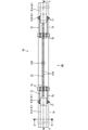
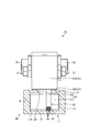
- a perspective view showing a slide device The perspective view which shows a slide apparatus from the direction different from FIG. 2 Top view showing the slide device Side view showing the slide device AA cross section of FIG. 4 BB sectional view of FIG. 4 The perspective view which shows the slide device of Embodiment 2 The perspective view which shows a slide apparatus from the direction different from FIG. 8 Top view showing the slide device Side view showing the slide device CC sectional view of FIG. 10 DD cross section of FIG. 10
- the slide device 10 of the present embodiment is mounted, for example, between the vehicle body of a vehicle such as a car and the seat 50.
- the X direction in FIG. 1 will be described as right, the Y direction as upper, and the Z direction as front.
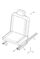
- the seat 50 is slidable in the front-rear direction with respect to a pair of metal rails 11 fixed on the floor of a passenger compartment of a vehicle body (not shown).
- the seat 50 is provided with various electric components such as, for example, an electric reclining device, a seat heater, a sensor that detects the presence or absence of seating of an occupant, and a sensor that detects the presence or absence of a seat belt.
- the slide device 10 includes a pair of rails 11 having an insertion groove 12A formed in the upper part, and a slider 20 having a slide insertion portion 23 slidably inserted in the insertion groove 12A.
- a cover 25 covering the insertion groove 12A (the cover in the closed state closing the insertion groove 12A is shown as 25A, and the cover in the open state not showing the insertion groove 12A as 25B), and the cover changing the closed state and the open state of the cover 25 And an opening / closing unit 30.
- the rails 11 are made of, for example, metal such as steel and aluminum, and are provided in pairs on the floor for each sheet 50.
- Each rail 11 is in the form of a rectangular tube having a through hole 11A penetrating in the front and rear direction, extends linearly in the front and rear direction, extends in parallel to each other, and faces a pair of opposing walls 12 and 14 It has a pair of side walls 13 and 15 which connect the both ends of opposing walls 12 and 14.
- an insertion groove 12A penetrating the opposing wall 12 extends in the front-rear direction.
- the insertion groove 12 ⁇ / b> A is provided at an intermediate portion in the width direction of the opposing wall 12, and linearly extends over the entire length of the rail 11.
- a wire harness 45 is inserted, for example, in the front of the slider 20 in one of the rails 11, and at positions adjacent to the front and sides of the rail 11, as shown in FIG. Is attached.
- the wire harness 45 in the rail 11 follows the seat 50 and moves in the front-rear direction, and the extra length portion not accommodated in the rail 11 in the wire harness 45 It can be accommodated.
- the wire harness 45 is electrically connected to various electrical components of the seat 50, and as shown in FIG. 7, the outer casing 47 has a rectangular cylindrical shape around a plurality of (four in the present embodiment) electric wires 46. It is surrounded by As each electric wire 46, for example, a coated electric wire in which a conductor portion such as a stranded wire or a single-core wire in which metal wires are twisted can be covered with an insulating layer can be used. For example, as shown in FIG. 5, one end side of the wire harness 45 can be drawn out laterally from above the insertion groove 12A and connected to the electrical component of the seat 50 through the side of the cover opening / closing portion 30. .
- the other end side of the wire harness 45 is, for example, an ECU (Electronic) via a wire harness wired on the floor of the vehicle body (below the mat or panel) or under the floor from the end accommodated in the extra length absorbing member 52, for example. It is connected to equipment such as Control Unit).
- ECU Electronic
- the slider 20 is made of, for example, synthetic resin or metal, and is inserted into the rail 11 so as to be slidable in the rail 11, and as shown in FIG. 21 and a slide insertion portion 23 which protrudes upward from the upper end portion of the slider main body 21 and is inserted into the insertion groove 12A.
- the slider main body 21 is fitted in a through hole 11A penetrating the front and rear of the rail 11, and is movable in the front and rear direction (the extending direction of the rail) of the through hole 11A.
- the slide insertion portion 23 has a plate shape extending in a direction perpendicular to the top surfaces of the slider main body 21 and the rail 11, and is inserted into the insertion groove 12A and connected to the cover opening / closing portion 30.
- the slide insertion portion 23 slides between notches formed in a mat or the like on the floor above the insertion groove 12A.
- a connection hole 24 (connection portion) connected to the cover opening / closing portion 30 is formed to penetrate.
- a through hole 20A through which the bolt 41 can be inserted is formed through an intermediate portion in the front-rear direction of the slider 20.
- the cover 25 is a flexible sheet-like member, and can be formed of, for example, a metal such as aluminum or an aluminum alloy, a synthetic resin such as an elastically deformable rubber, or a cloth.
- the cover 25 extends in a strip shape with a length corresponding to the length of the rail 11, and is formed with a constant width dimension larger than the width dimension of the insertion groove 12A and smaller than the width dimension of the opposing wall 12.
- the end of the cover 25 in the front-rear direction may be fixed to the upper surface of the rail 11 by a fixing member such as an adhesive or a bolt.
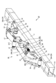
- the cover opening / closing portion 30 includes five (plural) rollers 31A to 31E which can be rotated in a state where the cover 25 is pressed, and support members 35 and 36 which rotatably support the five rollers 31A to 31E.
- the cover opening / closing portion 30 moves on the rail 11 along with the slide of the sheet 50, and the cover 25 is closed with the insertion groove 12A closed and the insertion groove 12A separated from the insertion groove 12A. It changes to the open state which is not closed.
- the plurality of rollers 31A to 31E are supported by the pair of first rollers 31A and 31E and the pair of second rollers 31B and 31D which are fixed to the support member 35 and restrict the moving direction (path) of the cover 25 and the support member 36. And a tension roller 31C that regulates the slack of the open cover 25B.
- the first rollers 31A and 31E are pivotally supported by each of the front and rear support members 35, and the path of the cover 25 switches between a closed state in which the insertion groove 12A is closed and an open state in which the insertion groove 12A is opened.
- the cover 25 is disposed in close contact with the upper surface (outer surface) of the cover 25.
- the second rollers 31B and 31D are disposed on the inner side of the first rollers 31A and 31E and in close contact with the inner surface of the cover 25B at a position separated from the upper surface of the rail 11, and the first rollers 31A and 31E
- the cover 25B between the second roller 31B and the second roller 31B and 31D extends in a direction inclined with respect to the upper surface of the rail 11.
- the cover 25B extending between the second roller 31B and the second roller 31D is pressed downward (toward the rail 11) by the tension roller 31C from the outside.
- the support members 35 and 36 are, as shown in FIGS. 2 and 3, four plate-shaped support members 35 for supporting the first rollers 31A and 31E and the second rollers 31B and 31D, and a support for supporting the tension roller 31C. And a member 36.
- the supporting members 35 are in the form of rectangular frames disposed opposite to each other, and the shaft portions 32 of the first rollers 31A, 31E and the second rollers 31B, 31D are provided at diagonal positions of the corner portions of the supporting members 35.
- the first roller 31A, 31E and the second roller 31B, 31D are rotatably supported by being fastened with the shaft portion 32 with a nut 37 as a fastening member.
- a separation restricting piece 35A that restricts the separation of the cover 25B protrudes inward.
- the pair of left and right support members 35 are connected by a rod-like portion 38 as a connection member, and are fastened and fixed to the outer surface of the support member 35 by a nut 43 as a fastening member.
- the rod-like portion 38 fixes the support member 35 and the slide insertion portion 23 by penetrating the connection hole 24 of the slide insertion portion 23.
- the bar-like portions 38 and the support members 35 may be tightened together with the support members 35 and, for example, the nuts 43 with the extension portions 51 extended downward of the sheet 50. And the sheet 50 may be fixed.
- the support member 36 has a pair of rod-like inclined pieces 36A and a U-shaped fixing member 40 for pivotally supporting the inclined pieces 36A.
- One end side of the inclined piece 36A rotatably supports the tension roller 31C, and the other end side is fixed to the slide insertion portion 23 through an elastic member 39 such as a helical spring.
- the tension roller 31C presses the cover 25B from the outside by the elastic force of the elastic member 39.
- the fixing member 40 is U-shaped, and as shown in FIG. 6, the bottom surface portion is fastened and fixed by a bolt 41 and a nut 42 which penetrate the through hole 20A of the slider 20.
- the inclined pieces 36 ⁇ / b> A are pivotally supported by a pair of rising pieces that rise from the bottom surface of the fixing member 40.
- the slide device 10 includes a cylindrical rail 11 in which an insertion groove 12A is formed, a slide insertion portion 23 slidably inserted in the insertion groove 12A, a cover 25 for closing the insertion groove 12A, and a slide in the insertion groove 12A.
- a cover opening / closing portion 30 capable of changing between a closed state in which the cover 25 closes the insertion groove 12A and an open state in which the insertion groove 12A is opened in accordance with the slide of the insertion portion 23 is provided.
- the cover opening / closing portion 30 changes the closed state in which the cover 25 closes the insertion groove 12A and the open state in which the insertion groove 12A is opened according to the slide of the slide insertion portion 23 in the insertion groove 12A. It is possible to prevent the cover 25 from obstructing the slide of the slide insertion portion 23.
- the slide insertion portion 23 is fixed to the seat 50 of the vehicle via the cover opening / closing portion 30 and slides along with the slide of the seat 50. If the insertion groove 12A is formed in the rail 11 for sliding the seat 50 of the vehicle, there is a concern that the foreign matter may enter from the insertion groove 12A into the rail, but according to the present embodiment, With respect to the rail 11 of the vehicle in which the foreign matter easily enters, it is possible to prevent a defect due to the foreign matter entering the rail 11.
- the cover opening / closing unit 30 moves along with the slide of the slide insertion unit 23, and changes the cover 25 from the closed state to the open state when the cover opening / closing unit 30 moves in the direction approaching the cover 25 in the closed state.
- the cover 25 is changed from the open state to the closed state.
- the cover 25 can be switched between the closed state and the open state according to the movement of the cover opening / closing portion 30, so the configuration is simplified as compared to the case of providing the structure for detecting the movement of the cover opening / closing portion.
- the cover 25B in the open state passes a position away from the rail 11, and the cover opening / closing unit 30 is movable between the cover 25B in the open state and the rail 11. In this way, the cover opening / closing portion 30 can be moved between the cover 25 and the rail 11 by detouring the path of the cover 25 to a position separated from the rail.
- the wire harness 45 is wired in the rail 11, and the wire harness 45 moves along with the movement of the cover opening / closing unit 30. This makes it possible to simplify the wiring path of the wire harness 45. Moreover, it can prevent that a malfunction arises in the path
- the second embodiment will be described with reference to FIGS. 8 to 13.
- the cover opening / closing unit 70 of the slide device 60 of the second embodiment winds the cover 61 by the front and rear rollers 71A and 71B.
- the other configuration is the same as that of the first embodiment. Therefore, in the following, the same configuration as that of the first embodiment is denoted by the same reference numeral, and the description is omitted.
- the slide device 60 does not cover the rail 11, the slider 20, and the cover 61 covering the insertion groove 12A (the cover in the closed state closing the insertion groove 12A is 61A and the insertion groove 12A
- the cover in the open state is illustrated as 61 B), and the cover opening / closing unit 70 that changes the closed state and the open state of the cover 61.
- the cover opening / closing unit 70 includes rollers 71A and 71B for winding the cover 61, and a fixing unit 73 for rotatably fixing the rollers 71A and 71B to the slide insertion unit 23.
- the fixing portion 73 includes a rod-like portion 38 penetrating the connection hole 24 of the slide insertion portion 23 and a connecting member 75 connecting the rod-like portion 38 and the shaft portion 72 of the rollers 71A and 71B.
- the connection member 75 is fastened and fixed to the rod portion 38 and the shaft portion 72 by nuts 76 and 77 as fastening members.
- the cover opening / closing unit 70 winds the cover 61 in accordance with the slide of the slide insertion unit 23. In this way, it is not necessary to provide a mechanism for bypassing the path of the cover 61, so the structure of the cover opening / closing unit 70 can be simplified.
- the cover opening / closing portions 30, 70 slide.
- the present invention is not limited to this.
- a sensor for detecting the position of the seat 50, the slide insertion portion 23, etc. is provided, and the cover is closed or opened by the electrical driving force of the cover opening / closing portion (without sliding the cover opening / closing portion). Good.
- the slide insertion portion is configured to be fixed to the slidable seat, but is not limited thereto.
- the slide insertion portion may be fixed to the slidable door.
- the number of electric wires constituting the wire harness is not limited to the number in the above embodiment, and can be changed to various numbers.
- the wire harness 45 is wired to one side of the rail 11 and the wire harness 45 is not wired to the other rail 11.
- the present invention is not limited to this.
- the wire harness 45 may not be arranged on both of the pair of rails 11.
- the rail 11 has a rectangular rectangular tube shape, but is not limited thereto.
- a square other than a rectangle or a polygonal tube other than a square may be used.
Landscapes
- Engineering & Computer Science (AREA)
- Mechanical Engineering (AREA)
- Aviation & Aerospace Engineering (AREA)
- Transportation (AREA)
- Seats For Vehicles (AREA)
Abstract
スライド装置10は、挿通溝12Aが形成された筒状のレール11と、挿通溝12Aにスライド可能に挿通されるスライド挿通部23と、挿通溝12Aを閉鎖するカバー25と、挿通溝12Aにおけるスライド挿通部23のスライドに応じてカバー25が挿通溝12Aを閉鎖する閉鎖状態と挿通溝12Aを開放する開放状態とを変えることが可能なカバー開閉部30とを備える。
Description
本明細書では、スライド装置に関する技術を開示する。
従来、自動車等の車両に固定されたレールに対してスライド可能なシートやドア等を備える技術が知られている。特許文献1では、シートレール内を仕切った左右一対の側部空間に車輪が回動自在に収容されている。一対の側部空間の間において上方側に開口する上面開口空間には車輪を軸支するシート脚部が配されており、シート脚部が上面開口空間をスライドするように構成されている。
ところで、特許文献1の構成では、シートレールの上部には、シート脚部がスライドするための上面開口空間が形成されている。そのため、この上面開口空間からレール内に異物が進入すると、シート脚部等のスライドの障害となることが懸念される。
本明細書に記載された技術は、上記のような事情に基づいて完成されたものであって、レール内への異物の進入を抑制することを目的とする。
本明細書に記載されたスライド装置は、挿通溝が形成された筒状のレールと、前記挿通溝にスライド可能に挿通されるスライド挿通部と、前記挿通溝を閉鎖するカバーと、前記挿通溝における前記スライド挿通部のスライドに応じて前記カバーが前記挿通溝を閉鎖する閉鎖状態と前記挿通溝を開放する開放状態とを変えることが可能なカバー開閉部と、を備える。
レールが挿通溝を有する構成では、挿通溝からレール内への異物の進入が懸念される。本構成によれば、レールの挿通溝はカバーにより覆われるため、挿通溝からレール内への異物の進入を抑制することができる。ここで、挿通溝を覆うカバーについては、挿通溝に挿通されるスライド挿通部のスライドの障害となることが懸念されるが、上記構成によれば、カバー開閉部により、挿通溝におけるスライド挿通部のスライドに応じてカバーが挿通溝を閉鎖する閉鎖状態と挿通溝を開放する開放状態とを変えることができるため、カバーがスライド挿通部のスライドの障害となることを抑制することができる。
本明細書に記載された技術の実施態様としては以下の態様が好ましい。
前記スライド挿通部は、車両のシートに対して固定されており、前記シートのスライドに伴ってスライドする。
車両のシートをスライドさせるためのレールに挿通溝が形成されていると、挿通溝からレール内への異物の進入の不具合が懸念されるが、本構成によれば、このような異物が進入しやすい車両のレールについて、レール内への異物の進入による不具合を防止することができる。
前記スライド挿通部は、車両のシートに対して固定されており、前記シートのスライドに伴ってスライドする。
車両のシートをスライドさせるためのレールに挿通溝が形成されていると、挿通溝からレール内への異物の進入の不具合が懸念されるが、本構成によれば、このような異物が進入しやすい車両のレールについて、レール内への異物の進入による不具合を防止することができる。
前記カバー開閉部は、前記スライド挿通部のスライドに伴って移動するとともに、前記カバー開閉部が前記閉鎖状態の前記カバーに近づく方向に移動すると前記カバーを前記閉鎖状態から前記開放状態に変えるとともに、前記カバー開閉部が前記開放状態の前記カバーから遠ざかる方向に移動すると前記カバーを前記開放状態から前記閉鎖状態に変える。
このようにすれば、カバー開閉部の移動に応じてカバーについて閉鎖状態と開放状態とを変えることができる。
このようにすれば、カバー開閉部の移動に応じてカバーについて閉鎖状態と開放状態とを変えることができる。
前記開放状態の前記カバーは前記レールから離間した位置を通るとともに、前記カバー開閉部は、前記開放状態の前記カバーと前記レールとの間を移動可能とされている。
このようにすれば、カバーの経路がレールから離間した位置に迂回することでカバーとレールとの間にカバー開閉部を移動させることが可能になる。
このようにすれば、カバーの経路がレールから離間した位置に迂回することでカバーとレールとの間にカバー開閉部を移動させることが可能になる。
前記カバー開閉部は、前記スライド挿通部のスライドに応じて前記カバーを巻回する。
このようにすれば、必ずしもカバーの経路を迂回させる機構を設ける必要がないため、カバー開閉部の構成を簡素化することが可能になる。
このようにすれば、必ずしもカバーの経路を迂回させる機構を設ける必要がないため、カバー開閉部の構成を簡素化することが可能になる。
前記レール内にワイヤーハーネスが配索されており、前記ワイヤーハーネスは、前記カバー開閉部の移動に伴って移動する。
このようにすれば、ワイヤーハーネスの配索経路を簡素化することが可能になる。また、異物の侵入によりワイヤーハーネスの経路に不具合が生じることを防止することができる。
このようにすれば、ワイヤーハーネスの配索経路を簡素化することが可能になる。また、異物の侵入によりワイヤーハーネスの経路に不具合が生じることを防止することができる。
本明細書に記載された技術によれば、レール内への異物の進入を抑制することができる。
<実施形態1>
実施形態1について、図1~図7を参照しつつ説明する。
本実施形態のスライド装置10は、例えば自動車等の車両の車体とシート50との間に装着される。以下では、図1のX方向を右方、Y方向を上方、Z方向を前方として説明する。
実施形態1について、図1~図7を参照しつつ説明する。
本実施形態のスライド装置10は、例えば自動車等の車両の車体とシート50との間に装着される。以下では、図1のX方向を右方、Y方向を上方、Z方向を前方として説明する。
シート50は、図1に示すように、図示しない車体の乗員室の床上に固定された一対の金属製のレール11に対して前後方向にスライド可能とされている。シート50には、例えば、電動リクライニング装置、シートヒータ、乗員の着座の有無を検出するセンサ、シートベルトの装着の有無を検出するセンサなどの各種電装品が備えられている。
(スライド装置10)
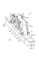
スライド装置10は、図6,図7に示すように、上部に挿通溝12Aが形成された一対のレール11と、挿通溝12Aにスライド可能に挿通されるスライド挿通部23を有するスライダ20と、挿通溝12Aを覆うカバー25(挿通溝12Aを塞ぐ閉鎖状態のカバーを25A,挿通溝12Aを塞がない開放状態のカバーを25Bとして図示)と、カバー25の閉鎖状態と開放状態とを変えるカバー開閉部30とを備える。
スライド装置10は、図6,図7に示すように、上部に挿通溝12Aが形成された一対のレール11と、挿通溝12Aにスライド可能に挿通されるスライド挿通部23を有するスライダ20と、挿通溝12Aを覆うカバー25(挿通溝12Aを塞ぐ閉鎖状態のカバーを25A,挿通溝12Aを塞がない開放状態のカバーを25Bとして図示)と、カバー25の閉鎖状態と開放状態とを変えるカバー開閉部30とを備える。
(レール11)
レール11は、例えば、スチール、アルミニウム等の金属からなり、各シート50に対して床上に一対設けられている。各レール11は、前後方向に貫通する貫通孔11Aを有する角筒状であって、前後方向に直線状に延びており、互いに平行に延びて対向する一対の対向壁12,14と、一対の対向壁12,14の両端部を連結する一対の側壁13,15とを有する。上方側(シート50側)の対向壁12には、当該対向壁12を貫通する挿通溝12Aが前後方向に延びている。挿通溝12Aは、対向壁12の幅方向の中間部に設けられ、レール11の全長に亘って直線状に延びている。
レール11は、例えば、スチール、アルミニウム等の金属からなり、各シート50に対して床上に一対設けられている。各レール11は、前後方向に貫通する貫通孔11Aを有する角筒状であって、前後方向に直線状に延びており、互いに平行に延びて対向する一対の対向壁12,14と、一対の対向壁12,14の両端部を連結する一対の側壁13,15とを有する。上方側(シート50側)の対向壁12には、当該対向壁12を貫通する挿通溝12Aが前後方向に延びている。挿通溝12Aは、対向壁12の幅方向の中間部に設けられ、レール11の全長に亘って直線状に延びている。
一方のレール11内には、例えばスライダ20の前方にワイヤーハーネス45が挿通されており、このレール11の前方及び側方に隣接する位置には、図1に示すように、余長吸収部材52が装着されている。シート50が前後方向へスライドすると、レール11内のワイヤーハーネス45がシート50に追従して前後方向に移動するとともに、ワイヤーハーネス45におけるレール11内に収容されない余長部が余長吸収部材52に収容可能とされている。
ワイヤーハーネス45は、シート50の各種電装品に電気的に接続されており、図7に示すように、複数本(本実施形態では4本)の電線46の周りが角筒状の外装体47で包囲されている。各電線46は、例えば金属素線が撚り合わされた撚り線や単芯線等の導体部が絶縁層で被覆された被覆電線を用いることができる。ワイヤーハーネス45の一端側は、例えば、図5に示すように、挿通溝12Aの上方から側方に導出されてカバー開閉部30の側方を通ってシート50の電装品に接続することができる。ワイヤーハーネス45の他端側は、例えば余長吸収部材52に収容された端部から車体の床上(のマットやパネル等の下)や床下に配索されたワイヤーハーネスを介して例えばECU(Electronic Control Unit)等の機器に接続される。
(スライダ20)
スライダ20は、例えば、合成樹脂製又は金属製であって、レール11内に挿通されてレール11内をスライド可能とされており、図7に示すように、レール11内に挿通されるスライダ本体21と、スライダ本体21の上端部から上方に突出して挿通溝12Aに挿通されるスライド挿通部23とを有する。スライダ本体21は、レール11の前後を貫通する貫通孔11Aに嵌め入れられており、貫通孔11Aを前後方向(レールの延びる方向)に移動可能とされている。
スライダ20は、例えば、合成樹脂製又は金属製であって、レール11内に挿通されてレール11内をスライド可能とされており、図7に示すように、レール11内に挿通されるスライダ本体21と、スライダ本体21の上端部から上方に突出して挿通溝12Aに挿通されるスライド挿通部23とを有する。スライダ本体21は、レール11の前後を貫通する貫通孔11Aに嵌め入れられており、貫通孔11Aを前後方向(レールの延びる方向)に移動可能とされている。
スライド挿通部23は、スライダ本体21及びレール11の上面に対して直交する方向に延びる板状であって、挿通溝12Aに挿通されてカバー開閉部30に連結されている。スライド挿通部23は、挿通溝12Aの上方では、床上のマット等に形成された切り込みの間をスライドする。スライド挿通部23には、図6に示すように、カバー開閉部30に連結される連結孔24(連結部)が貫通形成されている。スライダ20における前後方向の中間部には、ボルト41を挿通可能な通し孔20Aが貫通形成されている。
(カバー25)
カバー25は、撓み変形可能なシート状の部材であって、例えば、アルミニウム、アルミニウム合金等の金属、弾性変形可能なゴム等の合成樹脂、布等から形成することができる。カバー25は、レール11の長さに応じた長さで帯状に延びており、挿通溝12Aの幅寸法よりも大きく、対向壁12の幅寸法よりも小さい一定の幅寸法で形成されている。カバー25の前後方向の端部は、レール11の上面に接着剤やボルト等の固定部材により固定してもよい。
カバー25は、撓み変形可能なシート状の部材であって、例えば、アルミニウム、アルミニウム合金等の金属、弾性変形可能なゴム等の合成樹脂、布等から形成することができる。カバー25は、レール11の長さに応じた長さで帯状に延びており、挿通溝12Aの幅寸法よりも大きく、対向壁12の幅寸法よりも小さい一定の幅寸法で形成されている。カバー25の前後方向の端部は、レール11の上面に接着剤やボルト等の固定部材により固定してもよい。
(カバー開閉部30)
カバー開閉部30は、カバー25を押圧した状態で回転可能とされる5個(複数)のローラ31A~31Eと、5個のローラ31A~31Eを回転可能に支持する支持部材35,36とを備える機構であって、シート50のスライドに伴ってカバー開閉部30がレール11上を移動し、カバー25を挿通溝12Aを塞ぐ閉鎖状態と、挿通溝12Aに対して離間して挿通溝12Aを塞がない開放状態とに変える。
カバー開閉部30は、カバー25を押圧した状態で回転可能とされる5個(複数)のローラ31A~31Eと、5個のローラ31A~31Eを回転可能に支持する支持部材35,36とを備える機構であって、シート50のスライドに伴ってカバー開閉部30がレール11上を移動し、カバー25を挿通溝12Aを塞ぐ閉鎖状態と、挿通溝12Aに対して離間して挿通溝12Aを塞がない開放状態とに変える。
複数のローラ31A~31Eは、支持部材35に固定されてカバー25の移動方向(経路)を規制する一対の第1ローラ31A,31E及び一対の第2ローラ31B,31Dと、支持部材36に支持され、開放状態のカバー25Bの弛みを規制するテンションローラ31Cとを有する。
第1ローラ31A,31Eは、前後の支持部材35のそれぞれに回動可能に軸支されており、カバー25の経路が挿通溝12Aを塞ぐ閉鎖状態と挿通溝12Aを開放する開放状態とに切り替わる境界の位置において、カバー25の上面(外面)に密着するように配される。第2ローラ31B,31Dは、第1ローラ31A,31Eよりも内側で、レール11の上面に対して離間した位置においてカバー25Bの内面に密着するように配されており、第1ローラ31A,31Eと第2ローラ31B,31Dとの間のカバー25Bは、レール11の上面に対して傾斜した方向に延びている。第2ローラ31Bと第2ローラ31Dとの間に延びるカバー25Bは、外側からテンションローラ31Cで下方(レール11側)に押圧されている。
支持部材35,36は、図2,図3に示すように、第1ローラ31A,31E及び第2ローラ31B,31Dを支持する4つの板状の支持部材35と、テンションローラ31Cを支持する支持部材36とを備える。支持部材35は、互いに対向配置された四角形の枠状であって、各支持部材35の角部の対角の位置に第1ローラ31A,31Eの軸部32と、第2ローラ31B,31Dの軸部32とのそれぞれが締結部材としてのナット37で締結されることにより、第1ローラ31A,31E及び第2ローラ31B,31Dが回動可能に支持されている。支持部材35には、カバー25Bの離脱を規制する離脱規制片35Aが内方に突出している。
また、左右一対の支持部材35は、連結部材としての棒状部38で連結され、支持部材35の外面に締結部材としてのナット43で締結されて固定されている。棒状部38は、図6に示すように、スライド挿通部23の連結孔24を貫通することにより、支持部材35とスライド挿通部23とを固定している。各棒状部38や支持部材35は、例えば、図5に示すように、シート50の下方に延出された延出部51を支持部材35と例えばナット43で共締めして、カバー開閉部30とシート50とを固定してもよい。
支持部材36は、一対の棒状の傾斜片36Aと、傾斜片36Aを回動可能に軸支するU字状の固定部材40とを有する。傾斜片36Aの一端側は、テンションローラ31Cを回動可能に支持し、他端側は、スライド挿通部23に対して、例えばつるまきばね等の弾性部材39を介して固定されている。テンションローラ31Cは弾性部材39の弾性力によりカバー25Bを外側から押圧する。固定部材40は、U字状であって、図6に示すように、スライダ20の通し孔20Aを貫通するボルト41とナット42により底面部が締結されて固定されている。傾斜片36Aは、固定部材40の底面部から起立する一対の起立片に回動可能に軸支される。
上記した構成により、シート50を前方にスライドさせると、カバー開閉部30がシート50と共に前方にスライドし、カバー開閉部30の前方側の閉鎖状態のカバー25Aが開放状態に変えられ、カバー開閉部30の後端部の開放状態のカバー25Bが閉鎖状態に変えられる。一方、シート50を後方にスライドさせると、カバー開閉部30がシート50と共に後方にスライドし、カバー開閉部30の後方側の閉鎖状態のカバー25Aが開放状態に変えられ、カバー開閉部30の前端部の開放状態のカバー25Bが閉鎖状態に変えられる。
本実施形態によれば、以下の作用、効果を奏する。
スライド装置10は、挿通溝12Aが形成された筒状のレール11と、挿通溝12Aにスライド可能に挿通されるスライド挿通部23と、挿通溝12Aを閉鎖するカバー25と、挿通溝12Aにおけるスライド挿通部23のスライドに応じてカバー25が挿通溝12Aを閉鎖する閉鎖状態と挿通溝12Aを開放する開放状態とを変えることが可能なカバー開閉部30とを備える。
スライド装置10は、挿通溝12Aが形成された筒状のレール11と、挿通溝12Aにスライド可能に挿通されるスライド挿通部23と、挿通溝12Aを閉鎖するカバー25と、挿通溝12Aにおけるスライド挿通部23のスライドに応じてカバー25が挿通溝12Aを閉鎖する閉鎖状態と挿通溝12Aを開放する開放状態とを変えることが可能なカバー開閉部30とを備える。
レール11が挿通溝12Aを有する構成では、挿通溝12Aからレール11内への異物の進入が懸念される。本実施形態によれば、レール11の挿通溝12Aはカバー25により覆われるため、挿通溝12Aからレール11内への異物の進入を抑制することができる。ここで、挿通溝12Aを覆うカバー25については、挿通溝12Aに挿通されるスライド挿通部23のスライドの障害となることが懸念される。本実施形態によれば、カバー開閉部30により、挿通溝12Aにおけるスライド挿通部23のスライドに応じてカバー25が挿通溝12Aを閉鎖する閉鎖状態と挿通溝12Aを開放する開放状態とを変えることができるため、カバー25がスライド挿通部23のスライドの障害となることを抑制することができる。
スライド挿通部23は、車両のシート50に対してカバー開閉部30を介して固定されており、シート50のスライドに伴ってスライドする。
車両のシート50をスライドさせるためのレール11に挿通溝12Aが形成されていると、挿通溝12Aからレール内への異物の進入の不具合が懸念されるが、本実施形態によれば、このような異物が進入しやすい車両のレール11について、レール11内への異物の進入による不具合を防止することができる。
車両のシート50をスライドさせるためのレール11に挿通溝12Aが形成されていると、挿通溝12Aからレール内への異物の進入の不具合が懸念されるが、本実施形態によれば、このような異物が進入しやすい車両のレール11について、レール11内への異物の進入による不具合を防止することができる。
カバー開閉部30は、スライド挿通部23のスライドに伴って移動するとともに、カバー開閉部30が閉鎖状態のカバー25に近づく方向に移動するとカバー25を閉鎖状態から開放状態に変えるとともに、カバー開閉部30が開放状態のカバー25から遠ざかる方向に移動するとカバー25を開放状態から閉鎖状態に変える。
このようにすれば、カバー開閉部30の移動に応じてカバー25について閉鎖状態と開放状態とを変えることができるため、スカバー開閉部の移動を検出する構成を設ける場合と比較して構成を簡素化することができる。
このようにすれば、カバー開閉部30の移動に応じてカバー25について閉鎖状態と開放状態とを変えることができるため、スカバー開閉部の移動を検出する構成を設ける場合と比較して構成を簡素化することができる。
開放状態のカバー25Bはレール11から離間した位置を通るとともに、カバー開閉部30は、開放状態のカバー25Bとレール11との間を移動可能とされている。
このようにすれば、カバー25の経路がレールから離間した位置に迂回することでカバー25とレール11との間にカバー開閉部30を移動させることが可能になる。
このようにすれば、カバー25の経路がレールから離間した位置に迂回することでカバー25とレール11との間にカバー開閉部30を移動させることが可能になる。
レール11内にワイヤーハーネス45が配索されており、ワイヤーハーネス45は、カバー開閉部30の移動に伴って移動する。
このようにすれば、ワイヤーハーネス45の配索経路を簡素化することが可能になる。また、異物の侵入によりワイヤーハーネス45の経路に不具合が生じることを防止することができる。
このようにすれば、ワイヤーハーネス45の配索経路を簡素化することが可能になる。また、異物の侵入によりワイヤーハーネス45の経路に不具合が生じることを防止することができる。
<実施形態2>
実施形態2について、図8~図13を参照しつつ説明する。実施形態2のスライド装置60のカバー開閉部70は、前後のローラ71A,71Bによりカバー61を巻回するものである。他の構成は実施形態1と同一であるため、以下では、実施形態1と同一の構成については同一の符号を付して説明を省略する。
実施形態2について、図8~図13を参照しつつ説明する。実施形態2のスライド装置60のカバー開閉部70は、前後のローラ71A,71Bによりカバー61を巻回するものである。他の構成は実施形態1と同一であるため、以下では、実施形態1と同一の構成については同一の符号を付して説明を省略する。
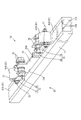
スライド装置60は、図11,図12に示すように、レール11と、スライダ20と、挿通溝12Aを覆うカバー61(挿通溝12Aを塞ぐ閉鎖状態のカバーを61A,挿通溝12Aを塞がない開放状態のカバーを61Bとして図示)と、カバー61の閉鎖状態と開放状態とを変化させるカバー開閉部70とを備える。
カバー開閉部70は、カバー61を巻回するローラ71A,71Bと、ローラ71A,71Bをスライド挿通部23に対して回動可能に固定する固定部73とを備える。固定部73は、スライド挿通部23の連結孔24を貫通する棒状部38と、棒状部38とローラ71A,71Bの軸部72とを連結する連結部材75とを備える。連結部材75は、棒状部38及び軸部72に対して締結部材としてのナット76,77で締結されて固定される。
シート50の移動に応じてカバー開閉部70が閉鎖状態のカバー61Aに対して近づく方向に移動すると、ローラ71A,71Bがカバー61に付勢されて回動し、カバー61を巻き取っていく。一方、カバー開閉部70が閉鎖状態のカバー61Aから遠ざかる方向に移動すると、ローラ71A,71Bは、開放状態とされたカバー61Bに付勢されて回動し、カバー61を挿通溝12Aに戻して閉鎖状態とする。
実施形態2によれば、カバー開閉部70は、スライド挿通部23のスライドに応じてカバー61を巻回する。
このようにすれば、必ずしもカバー61の経路を迂回させる機構を設ける必要がないため、カバー開閉部70の構成を簡素化することが可能になる。
このようにすれば、必ずしもカバー61の経路を迂回させる機構を設ける必要がないため、カバー開閉部70の構成を簡素化することが可能になる。
<他の実施形態>
本明細書に記載された技術は上記記述及び図面によって説明した実施形態に限定されるものではなく、例えば次のような実施形態も本明細書に記載された技術の技術的範囲に含まれる。
(1)上記実施形態では、カバー開閉部30,70がスライドする構成としたが、これに限られない。例えば、シート50やスライド挿通部23等の位置を検出するセンサを設け、(カバー開閉部はスライドさせず)カバー開閉部の電気的な駆動力によりカバーを閉鎖状態や開放状態とする構成としてもよい。
本明細書に記載された技術は上記記述及び図面によって説明した実施形態に限定されるものではなく、例えば次のような実施形態も本明細書に記載された技術の技術的範囲に含まれる。
(1)上記実施形態では、カバー開閉部30,70がスライドする構成としたが、これに限られない。例えば、シート50やスライド挿通部23等の位置を検出するセンサを設け、(カバー開閉部はスライドさせず)カバー開閉部の電気的な駆動力によりカバーを閉鎖状態や開放状態とする構成としてもよい。
(2)スライド挿通部は、スライド可能なシートに固定される構成したが、これに限られない。例えば、スライド可能なドアにスライド挿通部が固定される構成としてもよい。
(3)ワイヤーハーネスを構成する電線の本数は、上記実施形態の本数に限られず、種々の本数に変更することができる。
(3)ワイヤーハーネスを構成する電線の本数は、上記実施形態の本数に限られず、種々の本数に変更することができる。
(4)レール11の一方にワイヤーハーネス45を配索し、他方のレール11にワイヤーハーネス45を配索しない構成としたが、これに限られず、一対のレール11の双方にワイヤーハーネス45を配索したり、一対のレール11の双方にワイヤーハーネス45を配索しない構成としてもよい。
(5)レール11は、長方形の角筒状としたが、これに限られない。例えば、長方形以外の四角形や、四角形以外の多角形の筒状としてもよい。
10,60: スライド装置
11: レール
11A: 貫通孔
12A: 挿通溝
20: スライダ
23: スライド挿通部
25(25A,25B),61(61A,61B): カバー
30,70: カバー開閉部
31A~31E,71A,71B: ローラ
35,36: 支持部材
45: ワイヤーハーネス
50: シート
11: レール
11A: 貫通孔
12A: 挿通溝
20: スライダ
23: スライド挿通部
25(25A,25B),61(61A,61B): カバー
30,70: カバー開閉部
31A~31E,71A,71B: ローラ
35,36: 支持部材
45: ワイヤーハーネス
50: シート
Claims (6)
- 挿通溝が形成された筒状のレールと、
前記挿通溝にスライド可能に挿通されるスライド挿通部と、
前記挿通溝を閉鎖するカバーと、
前記挿通溝における前記スライド挿通部のスライドに応じて前記カバーが前記挿通溝を閉鎖する閉鎖状態と前記挿通溝を開放する開放状態とを変えることが可能なカバー開閉部と、を備えるスライド装置。 - 前記スライド挿通部は、車両のシートに対して固定されており、前記シートのスライドに伴ってスライドする、請求項1に記載のスライド装置。
- 前記カバー開閉部は、前記スライド挿通部のスライドに伴って移動するとともに、前記カバー開閉部が前記閉鎖状態の前記カバーに近づく方向に移動すると前記カバーを前記閉鎖状態から前記開放状態に変えるとともに、前記カバー開閉部が前記開放状態の前記カバーから遠ざかる方向に移動すると前記カバーを前記開放状態から前記閉鎖状態に変える、請求項1又は請求項2に記載のスライド装置。
- 前記開放状態の前記カバーは前記レールから離間した位置を通るとともに、前記カバー開閉部は、前記開放状態の前記カバーと前記レールとの間を移動可能とされている、請求項1から請求項3のいずれか一項に記載のスライド装置。
- 前記カバー開閉部は、前記スライド挿通部のスライドに応じて前記カバーを巻回する、請求項1から請求項4のいずれか一項に記載のスライド装置。
- 前記レール内にワイヤーハーネスが配索されており、前記ワイヤーハーネスは、前記カバー開閉部の移動に伴って移動する、請求項1から請求項5のいずれか一項に記載のスライド装置。
Priority Applications (3)
| Application Number | Priority Date | Filing Date | Title |
|---|---|---|---|
| CN201880036648.0A CN110740898A (zh) | 2017-06-21 | 2018-06-05 | 滑动装置 |
| DE112018003203.5T DE112018003203T5 (de) | 2017-06-21 | 2018-06-05 | Gleitvorrichtung |
| US16/623,068 US20200156509A1 (en) | 2017-06-21 | 2018-06-05 | Slide apparatus |
Applications Claiming Priority (2)
| Application Number | Priority Date | Filing Date | Title |
|---|---|---|---|
| JP2017-121196 | 2017-06-21 | ||
| JP2017121196A JP2019006170A (ja) | 2017-06-21 | 2017-06-21 | スライド装置 |
Publications (1)
| Publication Number | Publication Date |
|---|---|
| WO2018235585A1 true WO2018235585A1 (ja) | 2018-12-27 |
Family
ID=64736050
Family Applications (1)
| Application Number | Title | Priority Date | Filing Date |
|---|---|---|---|
| PCT/JP2018/021476 Ceased WO2018235585A1 (ja) | 2017-06-21 | 2018-06-05 | スライド装置 |
Country Status (5)
| Country | Link |
|---|---|
| US (1) | US20200156509A1 (ja) |
| JP (1) | JP2019006170A (ja) |
| CN (1) | CN110740898A (ja) |
| DE (1) | DE112018003203T5 (ja) |
| WO (1) | WO2018235585A1 (ja) |
Cited By (2)
| Publication number | Priority date | Publication date | Assignee | Title |
|---|---|---|---|---|
| CN109969047A (zh) * | 2019-04-26 | 2019-07-05 | 苏州车饰达智能科技有限公司 | 汽车座椅滑轨 |
| US11584263B2 (en) * | 2020-06-11 | 2023-02-21 | Shanghai Yanfeng Jinqiao Automotive Trim Systems Co. Ltd. | Vehicle interior component |
Families Citing this family (4)
| Publication number | Priority date | Publication date | Assignee | Title |
|---|---|---|---|---|
| JP7058577B2 (ja) * | 2018-09-13 | 2022-04-22 | トヨタ車体精工株式会社 | シートスライド装置 |
| FR3091501B1 (fr) | 2019-01-03 | 2022-07-15 | Faurecia Sieges Dautomobile | Dispositif de couverture d’une glissière de siège de véhicule et véhicule comprenant un tel dispositif |
| JP7517876B2 (ja) * | 2020-06-26 | 2024-07-17 | 三井住友建設株式会社 | 点検装置、および、点検システム |
| JP7641243B2 (ja) | 2022-01-20 | 2025-03-06 | 株式会社日立エルジーデータストレージ | バッテリ台 |
Citations (6)
| Publication number | Priority date | Publication date | Assignee | Title |
|---|---|---|---|---|
| JPS6297043U (ja) * | 1985-12-10 | 1987-06-20 | ||
| JPH0665067U (ja) * | 1993-02-26 | 1994-09-13 | 池田物産株式会社 | シートのスライド機構 |
| FR2848926A1 (fr) * | 2002-12-20 | 2004-06-25 | Cera | Disositif de recouvrement d'une glissiere de siege, notamment de vehicule automobile |
| FR2902711A1 (fr) * | 2006-06-26 | 2007-12-28 | Cera | Ensemble de glissiere de siege de vehicule automobile comprenant une bande mise en tension |
| WO2010137970A2 (en) * | 2009-05-26 | 2010-12-02 | Sun Marine Seats B.V. | Rail system for a displaceable seat |
| JP2012045994A (ja) * | 2010-08-25 | 2012-03-08 | Sumitomo Wiring Syst Ltd | スライド配線装置 |
Family Cites Families (2)
| Publication number | Priority date | Publication date | Assignee | Title |
|---|---|---|---|---|
| US7000967B2 (en) * | 2002-12-27 | 2006-02-21 | Ts Tech Co., Ltd. | Slidable vehicle seat provided with automotive electronic parts |
| CN102216121B (zh) * | 2008-12-16 | 2013-10-16 | 矢崎总业株式会社 | 线束布设装置 |
-
2017
- 2017-06-21 JP JP2017121196A patent/JP2019006170A/ja active Pending
-
2018
- 2018-06-05 DE DE112018003203.5T patent/DE112018003203T5/de not_active Ceased
- 2018-06-05 US US16/623,068 patent/US20200156509A1/en not_active Abandoned
- 2018-06-05 CN CN201880036648.0A patent/CN110740898A/zh active Pending
- 2018-06-05 WO PCT/JP2018/021476 patent/WO2018235585A1/ja not_active Ceased
Patent Citations (6)
| Publication number | Priority date | Publication date | Assignee | Title |
|---|---|---|---|---|
| JPS6297043U (ja) * | 1985-12-10 | 1987-06-20 | ||
| JPH0665067U (ja) * | 1993-02-26 | 1994-09-13 | 池田物産株式会社 | シートのスライド機構 |
| FR2848926A1 (fr) * | 2002-12-20 | 2004-06-25 | Cera | Disositif de recouvrement d'une glissiere de siege, notamment de vehicule automobile |
| FR2902711A1 (fr) * | 2006-06-26 | 2007-12-28 | Cera | Ensemble de glissiere de siege de vehicule automobile comprenant une bande mise en tension |
| WO2010137970A2 (en) * | 2009-05-26 | 2010-12-02 | Sun Marine Seats B.V. | Rail system for a displaceable seat |
| JP2012045994A (ja) * | 2010-08-25 | 2012-03-08 | Sumitomo Wiring Syst Ltd | スライド配線装置 |
Cited By (2)
| Publication number | Priority date | Publication date | Assignee | Title |
|---|---|---|---|---|
| CN109969047A (zh) * | 2019-04-26 | 2019-07-05 | 苏州车饰达智能科技有限公司 | 汽车座椅滑轨 |
| US11584263B2 (en) * | 2020-06-11 | 2023-02-21 | Shanghai Yanfeng Jinqiao Automotive Trim Systems Co. Ltd. | Vehicle interior component |
Also Published As
| Publication number | Publication date |
|---|---|
| CN110740898A (zh) | 2020-01-31 |
| US20200156509A1 (en) | 2020-05-21 |
| JP2019006170A (ja) | 2019-01-17 |
| DE112018003203T5 (de) | 2020-03-05 |
Similar Documents
| Publication | Publication Date | Title |
|---|---|---|
| WO2018235585A1 (ja) | スライド装置 | |
| JP6766768B2 (ja) | ワイヤーハーネス配索装置 | |
| US9308833B2 (en) | Harness wiring apparatus | |
| US7000967B2 (en) | Slidable vehicle seat provided with automotive electronic parts | |
| US9963092B2 (en) | Electrical wire routing apparatus | |
| US7073764B2 (en) | Seat track mechanism for vehicle seat | |
| US8937250B2 (en) | Wiring harness guiding apparatus | |
| WO2013129206A1 (ja) | 車両用ドア開閉装置 | |
| JP2018191464A (ja) | ワイヤハーネス配索装置 | |
| WO2017056954A1 (ja) | スライド配線装置 | |
| CN110356566A (zh) | 用于载具的舱室的导轨系统 | |
| CN111095710B (zh) | 线束布设装置 | |
| JP6743744B2 (ja) | 外装体及びワイヤーハーネス | |
| JP2012201268A (ja) | スライドレール構造 | |
| JP5583086B2 (ja) | スライドシート用給電装置 | |
| JP2014177277A (ja) | スライドシート用給電装置 | |
| JP2016068779A (ja) | シートのケーブル保持装置 | |
| JP2011162134A (ja) | スライドシート用のワイヤハーネスの配索構造 | |
| JP5929841B2 (ja) | スライドシート用のワイヤハーネス配索装置 | |
| WO2017022446A1 (ja) | スライドシート用のワイヤハーネス配索装置 | |
| JP6295823B2 (ja) | 車両用ルーフ装置 | |
| JP6217704B2 (ja) | スライドシート用のワイヤハーネス配索装置 | |
| JP4074269B2 (ja) | 化粧部材の取付構造とそれを用いたスライド配索装置 | |
| WO2021049344A1 (ja) | ワイヤーハーネス配索装置 | |
| JP2006194358A (ja) | 直動装置及びこの直動装置を備えたスライド配索装置 |
Legal Events
| Date | Code | Title | Description |
|---|---|---|---|
| 121 | Ep: the epo has been informed by wipo that ep was designated in this application |
Ref document number: 18820900 Country of ref document: EP Kind code of ref document: A1 |
|
| 122 | Ep: pct application non-entry in european phase |
Ref document number: 18820900 Country of ref document: EP Kind code of ref document: A1 |