WO2018230140A1 - Outil électrique - Google Patents
Outil électrique Download PDFInfo
- Publication number
- WO2018230140A1 WO2018230140A1 PCT/JP2018/015809 JP2018015809W WO2018230140A1 WO 2018230140 A1 WO2018230140 A1 WO 2018230140A1 JP 2018015809 W JP2018015809 W JP 2018015809W WO 2018230140 A1 WO2018230140 A1 WO 2018230140A1
- Authority
- WO
- WIPO (PCT)
- Prior art keywords
- motor
- current
- axis
- torque
- permanent magnet
- Prior art date
Links
Images


Classifications
-
- B—PERFORMING OPERATIONS; TRANSPORTING
- B25—HAND TOOLS; PORTABLE POWER-DRIVEN TOOLS; MANIPULATORS
- B25B—TOOLS OR BENCH DEVICES NOT OTHERWISE PROVIDED FOR, FOR FASTENING, CONNECTING, DISENGAGING OR HOLDING
- B25B23/00—Details of, or accessories for, spanners, wrenches, screwdrivers
- B25B23/14—Arrangement of torque limiters or torque indicators in wrenches or screwdrivers
- B25B23/147—Arrangement of torque limiters or torque indicators in wrenches or screwdrivers specially adapted for electrically operated wrenches or screwdrivers
-
- H—ELECTRICITY
- H02—GENERATION; CONVERSION OR DISTRIBUTION OF ELECTRIC POWER
- H02P—CONTROL OR REGULATION OF ELECTRIC MOTORS, ELECTRIC GENERATORS OR DYNAMO-ELECTRIC CONVERTERS; CONTROLLING TRANSFORMERS, REACTORS OR CHOKE COILS
- H02P21/00—Arrangements or methods for the control of electric machines by vector control, e.g. by control of field orientation
- H02P21/24—Vector control not involving the use of rotor position or rotor speed sensors
- H02P21/26—Rotor flux based control
-
- H—ELECTRICITY
- H02—GENERATION; CONVERSION OR DISTRIBUTION OF ELECTRIC POWER
- H02P—CONTROL OR REGULATION OF ELECTRIC MOTORS, ELECTRIC GENERATORS OR DYNAMO-ELECTRIC CONVERTERS; CONTROLLING TRANSFORMERS, REACTORS OR CHOKE COILS
- H02P29/00—Arrangements for regulating or controlling electric motors, appropriate for both AC and DC motors
- H02P29/40—Regulating or controlling the amount of current drawn or delivered by the motor for controlling the mechanical load
Definitions
- the present disclosure relates to an electric tool including a motor control unit that controls a motor, for example.
- Patent Document 1 proposes an electric tool characterized in that a tightening torque is calculated from a motor driving current and a motor rotation speed, and the motor is stopped when the tightening torque exceeds a preset value.
- Patent Document 2 discloses a control device for an electric driver that detects screw tightening torque in the electric driver and intermittently supplies drive torque to the chuck until the completion of tightening is detected based on the detected torque. Has been.
- Motor excitation current includes motor excitation current that does not contribute to rotational torque.
- the inertial energy of the rotating body is not considered, There was a problem such as, and the correct tightening torque could not be set.
- An object of the present disclosure is to provide an electric tool capable of eliminating or simplifying a mechanical clutch mechanism by solving the above problems and enabling more accurate tightening torque setting only by motor control. is there.
- An electric tool comprising a permanent magnet synchronous motor and a control unit for controlling the operation of the permanent magnet synchronous motor
- the control unit includes a limiting unit that limits a current contributing to torque generation of the permanent magnet synchronous motor to a predetermined maximum set value based on a predetermined tightening torque.
- the generated torque of the motor can be controlled only by the current that contributes to the torque generation.
- the current value contributing to the generated torque can be dynamically limited to a maximum value that also takes into account the influence of the inertia energy of the rotating body. Therefore, according to the electric tool according to the present disclosure, more accurate tightening torque can be set only by motor control, and the mechanical clutch mechanism can be omitted or simplified.
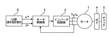
- FIG. 1 is a block diagram illustrating a configuration example of the power tool according to the first embodiment of the present disclosure.
- the electric tool according to the first embodiment is, for example, an electric driver, and includes a motor 1, an inverter circuit unit 2, a motor control unit 3, a gear 4, a chuck 5, and a user interface unit (UI unit). ) 6.
- UI unit user interface unit
- a motor 1 is constituted by a three-phase permanent magnet synchronous motor in which a permanent magnet is provided on a rotor (not shown) and an armature winding is provided on a stator (not shown), for example.
- armature winding and a rotor when an armature winding and a rotor are simply used, they mean an armature winding and a rotor of the motor 1 provided on the stator of the motor 1, respectively.
- the motor 1 is, for example, a salient pole machine (motor having salient polarity) represented by an embedded magnet type synchronous motor (IPMSM), but may be a non-salient pole machine.
- the motor 1 is rotatably connected to a chuck 5 on which a screw rotating bit is mounted, for example, via a gear 4.
- the inverter circuit unit 2 supplies a three-phase AC voltage composed of a U phase, a V phase, and a W phase to the armature winding of the motor 1 according to the rotor position of the motor 1.
- the motor control unit 3 has a position sensor-less control function for example, to estimate the rotor position and rotation speed of the motor 1 with a motor current I a, the operation of the motor 1 at a desired rotation speed and the target tightening torque A signal for causing this is given to the inverter circuit section 2.
- the desired rotational speed and the target tightening torque are set in advance by the user interface unit 6, and are linked to a motor switch command value by the motor control unit 3 in conjunction with a trigger switch (not shown) operated by the user. Output as ⁇ * and target tightening torque T * .
- FIG. 2 is an analysis model diagram of the motor 1 of the electric tool of FIG.
- U-phase, V-phase, and W-phase armature winding fixed axes are shown.
- the direction of the magnetic flux generated by the permanent magnet 1a is taken as the d-axis
- the estimated axis for control corresponding to the d-axis Is the ⁇ -axis.
- the q axis is taken as a phase advanced by 90 degrees in electrical angle from the d axis
- the estimated ⁇ axis is taken as phase advanced by 90 degrees in electrical angle from the ⁇ axis.
- the coordinate axis of the rotating coordinate system in which the d axis and the q axis are selected as the coordinate axes is referred to as a dq axis (real axis).
- the rotational coordinate system for control is a coordinate system in which the ⁇ -axis and the ⁇ -axis are selected as coordinate axes, and the coordinate axes are called ⁇ - ⁇ axes.
- the dq axes are rotating, and the rotation speed (that is, the rotation speed of the rotor of the motor 1) is called the actual motor speed ⁇ .
- the ⁇ - ⁇ axis is also rotating, and the rotation speed is called an estimated motor speed ⁇ e .
- the phase of the d axis is represented by ⁇ (actual rotor position ⁇ ) with respect to the U-phase armature winding fixed axis.
- the phase of the ⁇ axis is represented by ⁇ e (estimated rotor position ⁇ e ) with respect to the U-phase armature winding fixed axis.
- ⁇ e estimated rotor position
- the parameters ⁇ * , ⁇ , and ⁇ e are represented by electrical angular velocities.
- the ⁇ -axis component, ⁇ -axis component, d-axis component and q-axis component of the motor voltage V a are respectively expressed as ⁇ -axis voltage v ⁇ , ⁇ -axis voltage v ⁇ , d-axis voltage v d and q-axis voltage v.
- the ⁇ -axis component, ⁇ -axis component, d-axis component, and q-axis component of the motor current I a are respectively expressed as q , i.e., ⁇ -axis current i ⁇ , ⁇ -axis current i ⁇ , d-axis current i d, and q-axis current i q.
- Ra is a motor resistance (resistance value of the armature winding of the motor 1)
- L d and L q are d-axis inductance (d-axis component of inductance of the armature winding of the motor 1)
- q an axis inductance (q-axis component of inductance of the armature winding of the motor 1)
- the [Phi a the armature flux linkage ascribable to the permanent magnet 1a.
- L d , L q , R a and ⁇ a are values determined at the time of manufacturing the motor drive system for the electric tool, and these values are used in the calculation of the motor control unit 3.
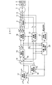
- FIG. 3 is a block diagram showing a detailed configuration example of the electric tool of FIG.
- the motor control unit 3 includes a current detector 11, a coordinate converter 12, a subtractor 13, a subtractor 14, a current control unit 15, a magnetic flux control unit 16, a speed control unit 17, a coordinate converter 18, a position A speed estimation unit 20 and a step-out detection unit 21 are provided.
- the current detector 11 is composed of, for example, a Hall element and the like.
- These currents may be detected by various existing current detection methods in which a shunt resistor or the like is incorporated in the inverter circuit unit 2.
- Coordinate converter 12 receives the detection result of the U-phase current i u and the V-phase current i v from the current detector 11, based on the estimated rotor position theta e from the position and speed estimation unit 20, the following equation According to (1), it is converted into ⁇ -axis current i ⁇ (current that controls the magnetic flux of the motor) and ⁇ -axis current i ⁇ (current that is directly proportional to the motor supply torque and directly contributes to the generation of motor rotation torque). To do.
- the position / speed estimation unit 20 estimates and outputs the estimated rotor position ⁇ e and the estimated motor speed ⁇ e .
- the method of estimating the estimated motor speed ⁇ e and the estimated rotor position theta e it is possible to use the method for example disclosed in Patent Document 3.
- the speed control unit 17 subtracts the estimated motor speed ⁇ e given from the position / speed estimation unit 20 from the motor speed command value ⁇ * given from the user interface unit 6, and obtains the subtraction result ( ⁇ * ⁇ e ).
- a ⁇ -axis current command value i ⁇ * is generated by inputting it into a PI (Proportional Interval) controller 51 (FIG. 4).
- * [delta] -axis current value i [delta] represents the current value to be followed by the motor current I a [delta] -axis component of a [delta] -axis current i [delta] is.
- the magnetic flux controller 16 outputs a ⁇ -axis current command value i ⁇ * .
- the ⁇ -axis current command value i ⁇ * and the estimated motor speed ⁇ e are referred to as necessary.
- the ⁇ -axis current command value i ⁇ * represents the value of the current that the ⁇ -axis current i ⁇ that is the ⁇ -axis component of the motor current I a should follow.
- the subtractor 13 subtracts the ⁇ -axis current i ⁇ output from the coordinate converter 12 from the ⁇ -axis current command value i ⁇ * output from the magnetic flux control unit 16, and obtains a current error (i ⁇ * as a result of the subtraction . -i ⁇ ) is calculated.
- the subtracter 14 subtracts the ⁇ -axis current i ⁇ output from the coordinate converter 12 from the ⁇ -axis current command value i ⁇ * output from the speed control unit 17, and obtains a current error (i ⁇ ) as a subtraction result. * ⁇ i ⁇ ) is calculated.
- the current control unit 15 receives each current error calculated by the subtractors 13 and 14 so that the ⁇ -axis current i ⁇ follows the ⁇ -axis current command value i ⁇ * , and the ⁇ -axis current i ⁇ is ⁇ .
- the ⁇ -axis voltage command value v ⁇ * and the ⁇ -axis voltage command value v ⁇ * are calculated and output so as to follow the shaft current command value i ⁇ * .
- the coordinate converter 18 performs reverse conversion of the ⁇ -axis voltage command value v ⁇ * and the ⁇ -axis voltage command value v ⁇ * based on the estimated rotor position ⁇ e given from the position / speed estimation unit 20, and voltage V a of the U-phase component, the U-phase voltage command value representing a V-phase component and a W-phase component v u *, V-phase voltage value v v * and the voltage command of the W-phase voltage command value v consisting w * three-phase Values are generated and output to the inverter circuit unit 2.
- equation (2) is used for this inverse transformation.
- the inverter circuit unit 2 generates a pulse-width-modulated signal based on three-phase voltage command values (v u * , v v *, and v w * ) representing the voltage to be applied to the motor 1, and voltage command value of the phase (v u *, v v * and v w *) of the motor current I a corresponding to the supplied to the armature winding of the motor 1 drives the motor 1.
- the step-out detection unit 21 estimates the rotation speed of the rotor using an estimation method (for example, refer to Patent Document 4) different from the estimation method of the rotation speed of the rotor employed in the position / speed estimation unit 20. If the difference is large, the motor 1 is forcibly stopped by assuming that the step-out has occurred.
- an estimation method for example, refer to Patent Document 4
- FIG. 4 is a block diagram showing a detailed configuration example of the speed control unit 17 of FIG.
- the output of the PI controller 51 generates a ⁇ -axis current command value i ⁇ * before current limit based on the subtraction result ( ⁇ * ⁇ e ) of the subtracter 50 and outputs the ⁇ -axis current command value i ⁇ * to the limiter 52.
- the limiter 52 outputs the output of the PI controller 51 as it is when the output of the PI controller 51 is equal to or less than the maximum set value i ⁇ * max of the limiter 52.
- the limit value calculation unit 53 calculates the maximum set value i ⁇ * max of the limiter 52 using the following equation (3), and sequentially updates the maximum set value i ⁇ * max of the limiter 52.
- K and J are constants
- d ⁇ / dt is a differential value of the angular velocity of the motor
- T is a predetermined target tightening torque.
- T0 is a predetermined loss torque, and may be previously set in a table or the like in the internal memory of the limit value calculation unit 53 as, for example, a dependent variable of the angular velocity ⁇ of the motor. Note that the angular speed ⁇ of the motor can be substituted by the estimated motor speed ⁇ e .
- the ⁇ -axis current is a current that is directly proportional to the supplied torque of the motor, and does not include an excitation current that does not directly contribute to the generation of the rotational torque of the motor.
- the command value i ⁇ * of the ⁇ -axis current is dynamically limited using the above-described equation (3). Therefore, more accurate tightening torque can be controlled in consideration of the inertia energy of the rotating body.
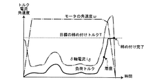
- the motor when the screw that is the work target of the electric tool is seated and the load torque increases rapidly, the motor is decelerated and finally stops. As the motor current decreases, the motor current gradually increases. During this time, tightening with a constant torque can be performed. Therefore, more accurate tightening torque can be set, and the mechanical clutch mechanism can be omitted or simplified.
Landscapes
- Engineering & Computer Science (AREA)
- Mechanical Engineering (AREA)
- Power Engineering (AREA)
- Control Of Ac Motors In General (AREA)
- Details Of Spanners, Wrenches, And Screw Drivers And Accessories (AREA)
- Control Of Motors That Do Not Use Commutators (AREA)
Abstract
Priority Applications (4)
| Application Number | Priority Date | Filing Date | Title |
|---|---|---|---|
| US16/618,841 US11396092B2 (en) | 2017-06-16 | 2018-04-17 | Electric power tool provided with motor controller controlling motor including limiter for limitting current contributing to torque generation |
| CN201880039522.9A CN110769981A (zh) | 2017-06-16 | 2018-04-17 | 电动工具 |
| EP18816964.3A EP3639977A4 (fr) | 2017-06-16 | 2018-04-17 | Outil électrique |
| JP2019525154A JPWO2018230140A1 (ja) | 2017-06-16 | 2018-04-17 | 電動工具 |
Applications Claiming Priority (2)
| Application Number | Priority Date | Filing Date | Title |
|---|---|---|---|
| JP2017-118961 | 2017-06-16 | ||
| JP2017118961 | 2017-06-16 |
Publications (1)
| Publication Number | Publication Date |
|---|---|
| WO2018230140A1 true WO2018230140A1 (fr) | 2018-12-20 |
Family
ID=64658677
Family Applications (1)
| Application Number | Title | Priority Date | Filing Date |
|---|---|---|---|
| PCT/JP2018/015809 WO2018230140A1 (fr) | 2017-06-16 | 2018-04-17 | Outil électrique |
Country Status (5)
| Country | Link |
|---|---|
| US (1) | US11396092B2 (fr) |
| EP (1) | EP3639977A4 (fr) |
| JP (1) | JPWO2018230140A1 (fr) |
| CN (1) | CN110769981A (fr) |
| WO (1) | WO2018230140A1 (fr) |
Cited By (4)
| Publication number | Priority date | Publication date | Assignee | Title |
|---|---|---|---|---|
| WO2021033432A1 (fr) * | 2019-08-22 | 2021-02-25 | パナソニックIpマネジメント株式会社 | Outil électrique |
| WO2021095533A1 (fr) * | 2019-11-15 | 2021-05-20 | パナソニックIpマネジメント株式会社 | Outil électrique, procédé de commande, procédé de détection de décrochage et programme |
| JP2021079509A (ja) * | 2019-11-21 | 2021-05-27 | パナソニックIpマネジメント株式会社 | 電動工具、制御方法、及びプログラム |
| JP2021079471A (ja) * | 2019-11-15 | 2021-05-27 | パナソニックIpマネジメント株式会社 | 電動工具、カムアウト検知方法及びプログラム |
Families Citing this family (1)
| Publication number | Priority date | Publication date | Assignee | Title |
|---|---|---|---|---|
| US11374520B2 (en) * | 2019-06-10 | 2022-06-28 | Black & Decker Inc. | Field-oriented sensorless brushless motor control in a power tool |
Citations (11)
| Publication number | Priority date | Publication date | Assignee | Title |
|---|---|---|---|---|
| JPS5264098A (en) * | 1975-11-14 | 1977-05-27 | Atlas Copco Ab | Motor type nut runner for fastening bolt joint up to desired fastening torque or fastening force |
| JPS5890474A (ja) * | 1981-11-18 | 1983-05-30 | 芝浦メカトロニクス株式会社 | 締付方法選択式ボルト締付装置 |
| JPH0326431A (ja) * | 1989-06-26 | 1991-02-05 | Nippon Mining Co Ltd | ねじ締め方法及び装置 |
| JPH05104454A (ja) * | 1991-10-15 | 1993-04-27 | Matsushita Electric Works Ltd | 電動工具 |
| JPH1080872A (ja) * | 1996-09-10 | 1998-03-31 | Toyota Motor Corp | 締め付け装置 |
| JPH10328952A (ja) * | 1997-06-02 | 1998-12-15 | Wako Giken:Kk | モータの制御方法及び装置並びにねじ締め方法及び装置 |
| JP3663638B2 (ja) | 1994-06-27 | 2005-06-22 | 松下電工株式会社 | 電動ドライバのトルク制御装置 |
| JP4198162B2 (ja) | 2006-04-07 | 2008-12-17 | 三洋電機株式会社 | モータ制御装置 |
| JP4480696B2 (ja) | 2005-08-26 | 2010-06-16 | 三洋電機株式会社 | モータ制御装置 |
| JP5182562B2 (ja) | 2008-02-29 | 2013-04-17 | 日立工機株式会社 | 電動工具 |
| JP2015100858A (ja) * | 2013-11-21 | 2015-06-04 | 株式会社マキタ | 電動工具 |
Family Cites Families (14)
| Publication number | Priority date | Publication date | Assignee | Title |
|---|---|---|---|---|
| US4210852A (en) | 1975-11-14 | 1980-07-01 | Atlas Copco Aktiebolag | Electric nutrunner |
| SE520096C2 (sv) * | 1998-12-10 | 2003-05-27 | Atlas Copco Tools Ab | System för kraftverktyg innefattande till- och frånkopplingsbar minnesmodul för lagring och överföring av data mellan olika enheter |
| JP4175098B2 (ja) | 2002-11-28 | 2008-11-05 | 富士電機機器制御株式会社 | 同期電動機の制御装置 |
| EP1447177B1 (fr) * | 2003-02-05 | 2011-04-20 | Makita Corporation | Outil motorisé à limitation de couple n'utilisant qu'un moyen de détection de déplacement angulaire |
| JP4082344B2 (ja) | 2003-12-09 | 2008-04-30 | 松下電工株式会社 | 電動機駆動装置およびそれを用いる電動工具 |
| EP1721383A1 (fr) * | 2004-03-05 | 2006-11-15 | In Motion Technologies Pty Ltd | Procede et dispositif de commande pour moteur electrique |
| DE102008040096A1 (de) * | 2008-07-02 | 2010-01-07 | Robert Bosch Gmbh | Verfahren zum Betreiben einer Elektrowerkzeugmaschine und eine Antriebseinheit für eine Elektrowerkzeugmaschine |
| CN103269832A (zh) | 2010-12-28 | 2013-08-28 | 日立工机株式会社 | 驱动工具 |
| JP2012139767A (ja) | 2010-12-28 | 2012-07-26 | Hitachi Koki Co Ltd | 締付工具 |
| JP5726022B2 (ja) | 2011-08-31 | 2015-05-27 | 株式会社マキタ | 電動工具 |
| JP2014069252A (ja) | 2012-09-28 | 2014-04-21 | Hitachi Koki Co Ltd | 電動工具 |
| JP6402472B2 (ja) | 2014-04-08 | 2018-10-10 | 日産自動車株式会社 | 車両用駆動制御装置及び車両用駆動制御方法 |
| CN105262394B (zh) | 2015-09-30 | 2018-01-16 | 南京埃斯顿自动控制技术有限公司 | 一种内置式永磁同步电机的mtpa控制方法及其控制系统 |
| CN105450123B (zh) | 2015-11-25 | 2017-12-05 | 浙江工业大学 | 一种基于神经网络的永磁同步电机混沌系统快速终端滑模控制方法 |
-
2018
- 2018-04-17 US US16/618,841 patent/US11396092B2/en active Active
- 2018-04-17 JP JP2019525154A patent/JPWO2018230140A1/ja active Pending
- 2018-04-17 WO PCT/JP2018/015809 patent/WO2018230140A1/fr active Application Filing
- 2018-04-17 EP EP18816964.3A patent/EP3639977A4/fr not_active Withdrawn
- 2018-04-17 CN CN201880039522.9A patent/CN110769981A/zh active Pending
Patent Citations (11)
| Publication number | Priority date | Publication date | Assignee | Title |
|---|---|---|---|---|
| JPS5264098A (en) * | 1975-11-14 | 1977-05-27 | Atlas Copco Ab | Motor type nut runner for fastening bolt joint up to desired fastening torque or fastening force |
| JPS5890474A (ja) * | 1981-11-18 | 1983-05-30 | 芝浦メカトロニクス株式会社 | 締付方法選択式ボルト締付装置 |
| JPH0326431A (ja) * | 1989-06-26 | 1991-02-05 | Nippon Mining Co Ltd | ねじ締め方法及び装置 |
| JPH05104454A (ja) * | 1991-10-15 | 1993-04-27 | Matsushita Electric Works Ltd | 電動工具 |
| JP3663638B2 (ja) | 1994-06-27 | 2005-06-22 | 松下電工株式会社 | 電動ドライバのトルク制御装置 |
| JPH1080872A (ja) * | 1996-09-10 | 1998-03-31 | Toyota Motor Corp | 締め付け装置 |
| JPH10328952A (ja) * | 1997-06-02 | 1998-12-15 | Wako Giken:Kk | モータの制御方法及び装置並びにねじ締め方法及び装置 |
| JP4480696B2 (ja) | 2005-08-26 | 2010-06-16 | 三洋電機株式会社 | モータ制御装置 |
| JP4198162B2 (ja) | 2006-04-07 | 2008-12-17 | 三洋電機株式会社 | モータ制御装置 |
| JP5182562B2 (ja) | 2008-02-29 | 2013-04-17 | 日立工機株式会社 | 電動工具 |
| JP2015100858A (ja) * | 2013-11-21 | 2015-06-04 | 株式会社マキタ | 電動工具 |
Non-Patent Citations (1)
| Title |
|---|
| See also references of EP3639977A4 |
Cited By (5)
| Publication number | Priority date | Publication date | Assignee | Title |
|---|---|---|---|---|
| WO2021033432A1 (fr) * | 2019-08-22 | 2021-02-25 | パナソニックIpマネジメント株式会社 | Outil électrique |
| WO2021095533A1 (fr) * | 2019-11-15 | 2021-05-20 | パナソニックIpマネジメント株式会社 | Outil électrique, procédé de commande, procédé de détection de décrochage et programme |
| JP2021079471A (ja) * | 2019-11-15 | 2021-05-27 | パナソニックIpマネジメント株式会社 | 電動工具、カムアウト検知方法及びプログラム |
| JP7390587B2 (ja) | 2019-11-15 | 2023-12-04 | パナソニックIpマネジメント株式会社 | 電動工具、カムアウト検知方法及びプログラム |
| JP2021079509A (ja) * | 2019-11-21 | 2021-05-27 | パナソニックIpマネジメント株式会社 | 電動工具、制御方法、及びプログラム |
Also Published As
| Publication number | Publication date |
|---|---|
| JPWO2018230140A1 (ja) | 2020-04-02 |
| EP3639977A4 (fr) | 2020-07-29 |
| CN110769981A (zh) | 2020-02-07 |
| EP3639977A1 (fr) | 2020-04-22 |
| US20210078145A1 (en) | 2021-03-18 |
| US11396092B2 (en) | 2022-07-26 |
Similar Documents
| Publication | Publication Date | Title |
|---|---|---|
| WO2018230141A1 (fr) | Outil rotatif à percussion | |
| WO2018230140A1 (fr) | Outil électrique | |
| JP4989075B2 (ja) | 電動機駆動制御装置及び電動機駆動システム | |
| JP5838038B2 (ja) | モータ制御装置 | |
| JP5748051B2 (ja) | 同期モータの印加電圧電気角設定方法とモータ制御装置 | |
| US20150311845A1 (en) | Motor drive device and electric compressor | |
| JP5652610B2 (ja) | モータ制御装置 | |
| JP2004187407A (ja) | モータ制御装置 | |
| JP7357204B2 (ja) | 電動工具、制御方法、プログラム | |
| JP5788057B1 (ja) | 同期機制御装置 | |
| KR102654519B1 (ko) | Bldc 모터 과부하 감지 장치 및 방법 | |
| JP5049163B2 (ja) | 電動オイルポンプ装置 | |
| JP2009290962A (ja) | 永久磁石形同期電動機の制御装置 | |
| JP5726273B2 (ja) | 永久磁石状態推定機能を備えた同期機制御装置およびその方法 | |
| JPH1118499A (ja) | 永久磁石型同期電動機のセンサレス速度制御方法及びその脱調検出方法 | |
| JP7153879B2 (ja) | 電動工具 | |
| JP7417899B2 (ja) | 電動工具システム、制御方法、及びプログラム | |
| JP5228435B2 (ja) | インバータ制御装置とその制御方法 | |
| JP2009165333A (ja) | 同期電動機の制御装置 | |
| JP5186352B2 (ja) | 電動機の磁極位置推定装置 | |
| TWI756975B (zh) | 馬達驅動方法 |
Legal Events
| Date | Code | Title | Description |
|---|---|---|---|
| 121 | Ep: the epo has been informed by wipo that ep was designated in this application |
Ref document number: 18816964 Country of ref document: EP Kind code of ref document: A1 |
|
| ENP | Entry into the national phase |
Ref document number: 2019525154 Country of ref document: JP Kind code of ref document: A |
|
| NENP | Non-entry into the national phase |
Ref country code: DE |
|
| WWE | Wipo information: entry into national phase |
Ref document number: 2018816964 Country of ref document: EP |
|
| ENP | Entry into the national phase |
Ref document number: 2018816964 Country of ref document: EP Effective date: 20200116 |