WO2018221538A1 - Dispositif de transmission à courroie dentée - Google Patents
Dispositif de transmission à courroie dentée Download PDFInfo
- Publication number
- WO2018221538A1 WO2018221538A1 PCT/JP2018/020622 JP2018020622W WO2018221538A1 WO 2018221538 A1 WO2018221538 A1 WO 2018221538A1 JP 2018020622 W JP2018020622 W JP 2018020622W WO 2018221538 A1 WO2018221538 A1 WO 2018221538A1
- Authority
- WO
- WIPO (PCT)
- Prior art keywords
- belt
- teeth
- toothed
- tooth
- toothed belt
- Prior art date
Links
Images


Classifications
-
- C—CHEMISTRY; METALLURGY
- C08—ORGANIC MACROMOLECULAR COMPOUNDS; THEIR PREPARATION OR CHEMICAL WORKING-UP; COMPOSITIONS BASED THEREON
- C08G—MACROMOLECULAR COMPOUNDS OBTAINED OTHERWISE THAN BY REACTIONS ONLY INVOLVING UNSATURATED CARBON-TO-CARBON BONDS
- C08G18/00—Polymeric products of isocyanates or isothiocyanates
- C08G18/06—Polymeric products of isocyanates or isothiocyanates with compounds having active hydrogen
- C08G18/28—Polymeric products of isocyanates or isothiocyanates with compounds having active hydrogen characterised by the compounds used containing active hydrogen
- C08G18/40—High-molecular-weight compounds
- C08G18/42—Polycondensates having carboxylic or carbonic ester groups in the main chain
-
- C—CHEMISTRY; METALLURGY
- C08—ORGANIC MACROMOLECULAR COMPOUNDS; THEIR PREPARATION OR CHEMICAL WORKING-UP; COMPOSITIONS BASED THEREON
- C08L—COMPOSITIONS OF MACROMOLECULAR COMPOUNDS
- C08L75/00—Compositions of polyureas or polyurethanes; Compositions of derivatives of such polymers
- C08L75/04—Polyurethanes
-
- F—MECHANICAL ENGINEERING; LIGHTING; HEATING; WEAPONS; BLASTING
- F16—ENGINEERING ELEMENTS AND UNITS; GENERAL MEASURES FOR PRODUCING AND MAINTAINING EFFECTIVE FUNCTIONING OF MACHINES OR INSTALLATIONS; THERMAL INSULATION IN GENERAL
- F16G—BELTS, CABLES, OR ROPES, PREDOMINANTLY USED FOR DRIVING PURPOSES; CHAINS; FITTINGS PREDOMINANTLY USED THEREFOR
- F16G1/00—Driving-belts
- F16G1/14—Driving-belts made of plastics
- F16G1/16—Driving-belts made of plastics with reinforcement bonded by the plastic material
-
- F—MECHANICAL ENGINEERING; LIGHTING; HEATING; WEAPONS; BLASTING
- F16—ENGINEERING ELEMENTS AND UNITS; GENERAL MEASURES FOR PRODUCING AND MAINTAINING EFFECTIVE FUNCTIONING OF MACHINES OR INSTALLATIONS; THERMAL INSULATION IN GENERAL
- F16G—BELTS, CABLES, OR ROPES, PREDOMINANTLY USED FOR DRIVING PURPOSES; CHAINS; FITTINGS PREDOMINANTLY USED THEREFOR
- F16G1/00—Driving-belts
- F16G1/28—Driving-belts with a contact surface of special shape, e.g. toothed
-
- F—MECHANICAL ENGINEERING; LIGHTING; HEATING; WEAPONS; BLASTING
- F16—ENGINEERING ELEMENTS AND UNITS; GENERAL MEASURES FOR PRODUCING AND MAINTAINING EFFECTIVE FUNCTIONING OF MACHINES OR INSTALLATIONS; THERMAL INSULATION IN GENERAL
- F16H—GEARING
- F16H7/00—Gearings for conveying rotary motion by endless flexible members
- F16H7/02—Gearings for conveying rotary motion by endless flexible members with belts; with V-belts
Definitions
- the present invention includes a toothed belt in which belt teeth and belt tooth bottom portions are alternately formed, and a toothed pulley in which pulley teeth and pulley tooth bottom portions are alternately formed so as to mesh with the toothed belt.
- the present invention relates to a toothed belt transmission.
- the toothed belt transmission is widely used in the general industrial and agricultural fields as a lifting and conveying device, and may be used as a blade angle adjusting device in a wind power generator.
- the toothed belt of the toothed belt transmission is required to have improved wear resistance.
- Patent Documents 1 and 2 disclose techniques for improving the wear resistance of a toothed belt.
- a phenomenon occurs in which the toothed belt and the toothed pulley sway little by little due to the influence of the wind.
- the belt tooth bottom portion of the toothed belt is worn by friction with the pulley teeth, and the strength of the toothed belt may be reduced, and the toothed belt may be broken.
- An object of the present invention is to provide a toothed belt transmission device capable of suppressing wear of a belt tooth bottom portion of a toothed belt.
- the belt tooth tip contacts the pulley tooth bottom, the pulley tooth tip does not contact the belt tooth bottom, and a gap is provided between the pulley tooth tip and the belt tooth bottom.
- a toothed belt transmission is provided.
- the transmission of power is realized by the tip of the belt teeth coming into contact with the bottom of the pulley tooth, and the tip of the pulley teeth is not in contact with the bottom of the belt tooth and a gap is provided between them.
- the belt tooth bottom does not wear due to friction with the pulley teeth, and wear of the belt tooth bottom can be suppressed.
- the gap may be 5 to 11% of the height of the belt teeth. If the gap is less than 5% of the height of the belt teeth, there may be a problem that the wear of the belt tooth bottom cannot be suppressed. If the gap exceeds 11% of the height of the belt teeth, the wear of the belt tooth bottom can be suppressed, but there may be a problem that the durability of the belt teeth is hindered. On the other hand, according to the said structure, these problems can be suppressed.
- a backlash of 2.5 to 3.5% of the width of the belt tooth at the center position is present between the belt tooth and the pulley tooth. May be provided. According to the said structure, interference with a belt tooth and a pulley tooth can be prevented and the positioning precision of a belt tooth and a pulley tooth can be ensured, suppressing abrasion of a belt tooth.
- the pitch of the belt teeth may be 14 mm or more, and the height of the belt teeth may be 5 mm or more. According to this configuration, the load resistance of the toothed belt can be increased.
- the toothed belt may include a back surface portion facing the belt teeth in a height direction of the belt teeth, and a plurality of core wires embedded in the back surface portion, each of the plurality of core wires being Steel cord, or a cord in which at least one of aramid fiber and carbon fiber is twisted.
- each of the plurality of core wires may be made of a steel cord, may have a strength of 7 to 8 kN, and may have a diameter of 2.3 to 2.6 mm. According to the said structure, the belt strength per 1 mm of belt width of a toothed belt can be improved by using as a core wire the steel cord which has the characteristics of low elongation and high strength.
- the pitch of the plurality of core wires may be 3.0 to 3.7 mm, and the interval between the plurality of core wires may be 0.4 to 1.4 mm. According to the said structure, the belt strength per 1 mm of belt widths of a toothed belt can be improved more reliably by the suitable combination of the pitch of a core wire and the space
- thermoplastic elastomer is integrally formed of a thermoplastic elastomer
- the thermoplastic elastomer is a polyurethane-based thermoplastic elastomer, a polyester-based thermoplastic elastomer, a polystyrene-based thermoplastic elastomer, a polyolefin-based thermoplastic elastomer, It may be at least one selected from the group consisting of a polyamide-based thermoplastic elastomer and a vinyl chloride-based thermoplastic elastomer.
- the back portion and the belt teeth may be integrally formed of a polyurethane thermoplastic elastomer having a hardness of 38 to 53 °. According to the said structure, the toothed belt excellent in the mechanical characteristics and durability can be obtained.
- the polyurethane-based thermoplastic elastomer is widely used for transmission belts and conveyor belts, it is easy to manufacture a toothed belt.
- a kind of polyurethane which comprises a polyurethane-type thermoplastic elastomer you may be a polyether type polyurethane, a polyester type polyurethane, or a polycarbonate type polyurethane.
- the belt strength per 1 mm belt width of the toothed belt may be 1.85 kN or more. According to this configuration, the load resistance of the toothed belt can be increased.
- a reinforcing cloth may be disposed on the surface of the belt tooth and the surface of the belt tooth bottom. According to the said structure, abrasion of a belt tooth can be suppressed.
- the transmission of power is realized by the tip of the belt teeth coming into contact with the bottom of the pulley tooth, and the tip of the pulley teeth is not in contact with the bottom of the belt tooth and a gap is provided between them.
- the belt tooth bottom does not wear due to friction with the pulley teeth, and wear of the belt tooth bottom can be suppressed.
- FIG. 1 is a side view (seen from an arrow direction I in FIG. 2) showing a part (with a reinforcing cloth) of a toothed belt transmission device according to an embodiment of the present invention, along the belt longitudinal direction.
- FIG. 2 is a cross-sectional view along the belt width direction (along line II-II in FIG. 1) showing the toothed belt included in the toothed belt transmission according to the embodiment of the present invention.
- Drawing 3 is a schematic diagram for explaining a manufacturing method of a toothed belt contained in a toothed belt transmission concerning one embodiment of the present invention.
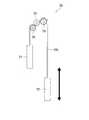
- FIG. 4 is a schematic diagram showing a running test machine used in the running test.
- FIG. 5 is a side view along the longitudinal direction of the belt, showing a part of the toothed belt transmission device (without reinforcing cloth) according to one embodiment of the present invention.
- the toothed belt transmission 1 includes a toothed belt 10 and a toothed pulley 50 as shown in FIG.
- the toothed belt 10 includes a plurality of core wires 11, a back surface portion 12 in which the plurality of core wires 11 are embedded, a plurality of belt teeth 13, and a plurality of belt tooth bottom portions 14.
- each core wire 11 is made of a steel cord (a cord obtained by twisting steel fibers).
- the plurality of core wires 11 extend in the belt longitudinal direction and are arranged in the belt width direction.
- the center position of the core wire 11 in the belt thickness direction is shown as the pitch line PL.
- the pitch line PL is a reference line in the belt longitudinal direction of the toothed belt 10 that maintains the same length without expanding and contracting in the belt longitudinal direction even when the toothed belt 10 is bent along the outer periphery of the toothed pulley 50. It is.
- the plurality of belt teeth 13 face the back surface portion 12 in the belt thickness direction (the height direction of the belt teeth 13), and are spaced apart from each other in the belt longitudinal direction.
- the back surface portion 12 and the plurality of belt teeth 13 are integrally formed of a thermoplastic elastomer.
- the thermoplastic elastomer constituting the back surface portion 12 and the plurality of belt teeth 13 is a polyurethane-based thermoplastic elastomer having a hardness of 38 to 53 ° (based on JIS K6253: 2012, measured with a D-type hardness meter). ).
- the type of polyurethane constituting the polyurethane-based thermoplastic elastomer is polyether type polyurethane, polyester type polyurethane, or polycarbonate type polyurethane.
- the reinforcing cloth 15 is composed of a woven cloth in which warps and wefts are woven by crossing them vertically and horizontally according to certain rules.
- the weave of the woven fabric may be either a twill weave or a satin weave.
- the form of warp and weft is either a multifilament yarn in which filaments (long fibers) are aligned or twisted, a monofilament yarn that is a single long fiber, or a spun yarn in which short fibers are twisted (spun yarn). May be.
- the warp or weft is a multifilament yarn or a spun yarn, it may be a blended yarn or a blended yarn using a plurality of types of fibers.
- any of nylon, aramid, polyester, polybenzoxazole, cotton, fluorine, or a combination thereof can be used as the material of the fibers constituting the reinforcing cloth 15.
- the reinforcing cloth 15 may be provided on the outer peripheral surface of the toothed belt 10 or may be provided only on the outer peripheral surface of the toothed belt 10. Further, the reinforcing cloth 15 may not be provided on the inner peripheral surface and the outer peripheral surface of the toothed belt 10.
- the belt teeth 13 and the belt tooth bottom portions 14 are alternately formed in the belt longitudinal direction.
- the belt tooth bottom portion 14 is a bottom portion of a recess formed between two belt teeth 13 adjacent to each other in the belt longitudinal direction.
- the belt tooth bottom portion 14 is constituted by a back surface portion 12 including a reinforcing cloth 15.
- the toothed belt 10 satisfies the following requirements.
- ⁇ Belt width W 20-200mm
- Total belt thickness H 9-15mm
- the height H13 of each belt tooth 13 (including the thickness of the reinforcing cloth 15) is 5 to 12 mm.
- ⁇ Pitch P13 of belt tooth 13 (distance on pitch line PL) 14 to 25 mm ⁇
- the diameter D of each core wire 11 is 2.3 to 2.6 mm.
- the toothed pulley 50 meshes with the toothed belt 10 and has a plurality of pulley teeth 53 and a plurality of pulley tooth bottoms 54.
- the pulley teeth 53 and the pulley tooth bottom 54 are alternately formed in the belt longitudinal direction.
- the pulley tooth bottom 54 is a bottom of a recess formed between two pulley teeth 53 adjacent in the belt longitudinal direction.
- the belt teeth 13 are arranged in a recess formed between two pulley teeth 53 adjacent in the belt longitudinal direction.
- Pulley teeth 53 are arranged in a recess formed between two belt teeth 13 adjacent in the belt longitudinal direction.
- the tip of the belt tooth 13 is in contact with the pulley tooth bottom 54, but the tip of the pulley tooth 53 is not in contact with the belt tooth bottom 14, and there is a gap between the tip of the pulley tooth 53 and the belt tooth bottom 14. S is provided. In the present embodiment, the gap S is 5 to 11% of the height H13 of the belt teeth 13.
- backlash feed screw used in the machine, between the belt teeth 13 and the pulley teeth 53 at the center position O of the belt teeth 13 in the belt thickness direction (belt tooth height direction).
- a mechanical element such as a gear that fits and moves with each other is provided with a gap (B) intentionally provided in the movement direction.
- the backlash B is 2.5 to 3.5% of the width W13 of the belt tooth 13 at the center position O.
- a backlash B is provided between each of the pulley teeth 53 adjacent to the other side.
- the toothed belt transmission device 1 can be used in a usage environment in which the tension applied to the toothed belt 10 is always 0.35 kN / mm or more, and the maximum tension is 0.80 to 0.95 kN / mm. It can be used as a blade angle adjusting device, a lifting and lowering conveying device or the like in a wind power generator.
- the toothed belt 10 is manufactured by, for example, a manufacturing apparatus 60 as shown in FIG.
- the manufacturing apparatus 60 includes a forming drum 61, pulleys 62 and 63 arranged close to the upper and lower sides of the forming drum 61, a pulley 64 arranged facing the forming drum 61 in the horizontal direction, and pulleys 62 to 64. It has a pressing band 65 that is a wound endless metal band, an extrusion head 66 that extrudes thermoplastic elastomer, a core wire supply device (not shown), and a reinforcing cloth supply device (not shown).
- the pulley 64 is movable in the horizontal direction with respect to the forming drum 61 and applies a predetermined tension to the pressing band 65.
- the pressing band 65 is disposed so as to wrap around the outer peripheral surface of the forming drum 61 about a half turn, and is pressed against the outer peripheral surface of the forming drum 61 by application of tension from the pulley 64.
- a reinforcing cloth supply device (not shown) supplies the reinforcing cloth 15 to the outer peripheral surface of the forming drum 61.
- the core wire supply device (not shown) supplies a plurality of core wires 11 arranged in the axial direction of the forming drum 61 to the outer peripheral surface side of the reinforcing cloth 15 supplied to the outer peripheral surface of the forming drum 61.
- the extrusion head 66 supplies the thermoplastic elastomer melted by heating to the outer peripheral surface side of the reinforcing cloth 15 and the core wire 11 supplied to the outer peripheral surface of the molding drum 61.
- thermoplastic elastomer, the plurality of core wires 11 and the reinforcing cloth 15 supplied to the outer peripheral surface of the molding drum 61 are caught between the molding drum 61 and the pressing band 65 as the molding drum 61 rotates. It is. At this time, the thermoplastic elastomer is filled into the groove formed on the outer peripheral surface of the molding drum 61 by the pressing force of the pressing band 65, and the belt teeth 13 are formed in the groove. At this time, the supplied reinforcing cloth 15 is filled in a groove formed on the outer peripheral surface of the forming drum 61 and arranged along the surface of the thermoplastic elastomer that becomes the belt teeth 13.
- a back surface portion 12 in which a plurality of core wires 11 are embedded is formed between the reinforcing cloth 15 and the pressing band 65 disposed on the outer peripheral surface of the forming drum 61.
- the thermoplastic elastomer is cooled and solidified while strongly pressing the thermoplastic elastomer against the outer peripheral surface of the molding drum 61 by the pressing force of the pressing band 65.
- the belt main body 10a is continuously taken out at a portion where the pressing band 65 is away from the forming drum 61.
- the tip of the belt teeth 13 is brought into contact with the pulley tooth bottom portion 54 so that power transmission is realized and the tip of the pulley teeth 53 is also achieved. Is not in contact with the belt tooth bottom portion 14 and the gap S is provided between them, so that the belt tooth bottom portion 14 does not wear due to friction with the pulley teeth 53 even if the above-mentioned slight vibration occurs. Wear of the belt bottom portion 14 can be suppressed.
- the gap S is 5 to 11% of the height H13 of the belt teeth 13. If the gap S is less than 5% of the height H13 of the belt teeth 13, there may arise a problem that the wear of the belt tooth bottom portion 14 cannot be suppressed. If the gap S exceeds 11% of the height H13 of the belt teeth 13, the wear of the belt tooth bottom portion 14 can be suppressed, but there may be a problem that the durability of the belt teeth 13 is hindered. On the other hand, according to the said structure, these problems can be suppressed.
- the width W13 of the belt teeth 13 at the central position O is 2.5 to 3.5%.
- a backlash B is provided. According to this configuration, it is possible to ensure the positioning accuracy between the belt teeth 13 and the pulley teeth 53 while preventing the belt teeth 13 and the pulley teeth 53 from interfering and suppressing the wear of the belt teeth 13.
- the pitch P13 of the belt teeth 13 is 14 mm or more, and the height H13 of the belt teeth 13 is 5 mm or more. According to this configuration, the load resistance of the toothed belt 10 can be increased.
- each core wire 11 of the toothed belt 10 is made of a steel cord, has a strength of 7 to 8 kN, and a diameter D of 2.3 to 2.6 mm. According to the said structure, the belt strength per 1 mm of belt width of the toothed belt 10 can be improved by using the steel cord which has the characteristics of low elongation and high strength as the core wire 11.
- the pitch P11 of the core wires 11 is 3.0 to 3.7 mm, and the distance d between the core wires 11 is 0.4 to 1.4 mm. According to the said structure, the belt strength per 1 mm of belt width of the toothed belt 10 can be improved more reliably by the suitable combination of the pitch P11 of the core wire 11, and the space
- the back surface portion 12 and the belt teeth 13 are integrally formed of a polyurethane-based thermoplastic elastomer having a hardness of 38 to 53 °. According to the said structure, the toothed belt 10 excellent in the mechanical characteristic and durability is obtained. In addition, since the polyurethane-based thermoplastic elastomer is widely used for a transmission belt and a conveyance belt, the toothed belt 10 can be easily manufactured.
- the belt strength per 1 mm belt width of the toothed belt 10 is 1.85 kN or more. According to this configuration, the load resistance of the toothed belt 10 can be increased.
- a reinforcing cloth 15 is disposed on the surface of the belt teeth 13 and the surface of the belt tooth bottom portion 14. According to this configuration, wear of the belt teeth 13 can be suppressed.
- the toothed belt 10 in which the reinforcing cloth 15 is provided on the inner peripheral surface of the toothed belt 10 (the surface of the plurality of belt teeth 13 and the surface of the plurality of belt tooth bottom portions 14) has been described.
- the reinforcing cloth 15 since the reinforcing cloth 15 may not be provided on the inner peripheral surface of the toothed belt 10, the toothed belt 110 without the reinforcing cloth 15 is shown in FIG.
- the toothed belt 110 includes a belt body 10 a having a plurality of core wires 11, a back surface portion 12 in which the plurality of core wires 11 are embedded, a plurality of belt teeth 13, and a plurality of belt tooth bottom portions 14. . Since the toothed belt 110 is the same as the toothed belt 10 shown in FIG. 1 except that the reinforcing cloth 15 is not provided, the reference numerals of the configuration of the toothed belt 110 shown in FIG. The reference numerals of the configuration of the toothed belt 10 described in the above are common, and the description is omitted.
- the inventor of the present application manufactured the toothed belts according to Examples 1 to 22 and Comparative Examples 1 and 2 by using the polyurethane-based or polyester-based thermoplastic elastomer by the above-described manufacturing method. Tests and tensile tests were performed. The configurations and test results of the toothed belts according to Examples 1 to 22 and Comparative Examples 1 to 2 are shown in Tables 1 to 7 below.
- Table 1 in order to compare the case where the value (distance) of the gap S between the tip of the pulley teeth and the belt tooth bottom is varied, the toothed belts of Examples 1 to 6 and Comparative Example 1 are compared.
- the configuration is described.
- Table 2 the configurations of the toothed belts of Examples 3 and 7 to 11 are described in order to compare the case where the value (distance) of the backlash B between the belt teeth 13 and the pulley teeth 53 is varied. is doing.
- Table 3 shows the configurations of the toothed belts of Examples 3 and 12 to 13 in order to compare the case where the tooth scale (tooth pitch P13, tooth height H13) of the toothed belt is changed. Yes.
- Table 4 the configurations of the toothed belts of Examples 3 and 14 to 16 are compared in order to compare the case where the hardness of the back surface portion and the belt teeth integrally formed with the polyurethane (polyester type) thermoplastic elastomer is varied. Is described.
- Table 5 shows the configurations of the toothed belts of Examples 3 and 17 to 18 in order to compare the case where the pitch P11 of the core wire is changed.
- Table 6 a toothed belt (Example 3) in which the back surface and the belt teeth are integrally formed with a polyurethane-based thermoplastic elastomer, and a toothed belt in which the back surface and the belt teeth are integrally formed with a polyester-based thermoplastic elastomer are shown.
- Example 19 The configuration of (Example 19) is described. Further, in Table 7, in order to compare the case where the reinforcing cloth is provided on the inner peripheral surface of the toothed belt (the surface of the belt teeth and the surface of the belt tooth bottom), and the case where the reinforcing cloth is not provided, Examples 1, 3 6, Comparative Example 1 and Examples 20 to 22 and Comparative Example 2 are described.
- a test piece 10x having a width of 20 mm and a length of 3000 mm was sampled from each toothed belt according to Examples 1 to 22 and Comparative Examples 1 and 2, and as shown in FIG.
- test pieces having a width of 20 mm and a length of 500 mm were taken from the toothed belts according to Examples 1 to 22 and Comparative Examples 1 and 2, and each test piece was subjected to a tensile test using an Amsler tensile tester. (Tensile speed 50 mm / min) was performed and the belt strength until breaking was measured. The measurement was performed before and after the above-described running test (see the items “Before Running” and “After Running” in “Belt Strength” in Tables 1 to 7).
- Example 1 Of Examples 1 to 6 in which there was a gap S between the tip of the pulley teeth and the bottom of the belt tooth, Examples 2 to 5 were all ranked A.
- Example 1 With the smallest gap S, the belt tooth bottom part was slightly worn, and was ranked B. Further, the larger the gap S is, the more the belt tooth bottom part does not come into contact with the pulley teeth when meshing with the pulley teeth, so that the belt teeth receive stress concentrated on the toothed belt (the belt tooth bottom part comes into contact with the pulley teeth). The stress is distributed to the belt teeth and the bottom of the belt teeth). Therefore, in Example 6 with the largest gap S, the stress easily concentrates on the belt teeth, and the belt teeth are likely to be worn by contact with the pulley teeth, and thus rank B.
- Comparative Example 1 is a case where there is no gap S between the tip of the pulley teeth and the bottom of the belt, the wear of the bottom of the belt is severe and the C rank.
- Examples 7 to 11 have the same configuration as that of Example 3 except that the backlash B is varied (the belt tooth pitch P13 is 14 mm, the belt tooth pitch P13 is relatively large, and the belt tooth pitch P13).
- Belt tooth scale (the length of the belt teeth in the longitudinal direction of the belt and the height H13 of the belt teeth is large)).
- the A rank was the same as that in Example 3.
- the belt teeth were worn due to interference between the pulley teeth and the belt teeth, and the B ranks.
- Example 11 with a large backlash amount the belt teeth were worn due to the interference between the pulley teeth and the belt teeth as the belt teeth were deformed.
- Examples 12 and 13 are large, high-strength toothed belts having the same configuration as in Example 3, and the tooth scale (the length of the belt teeth in the longitudinal direction of the belt and the height H13 of the belt teeth) is larger.
- the toothed belt was A rank as in Example 3.
- Examples 14 to 16 are large in size (belt tooth pitch P13 is 14 mm) and have high strength, except that the hardness of the material constituting the toothed belt (polyurethane thermoplastic elastomer) is changed. It is a toothed belt. In the toothed belt having a low hardness, the wear of the belt teeth is likely to proceed due to the deformation of the belt teeth.
- Examples 17 and 18 are large (belt tooth pitch P13 is the same as in Example 3) except that the number of core wires embedded in the toothed belt is reduced by changing (enlarging) the core wire pitch P11. 14 mm) and a high-strength toothed belt. Although the belt strength is lower than that of Example 3 due to the decrease in the number of the core wires, the belt strength is maintained at 1.85 kN / mm or more after running, and the belt teeth and the belt tooth bottom wear. It was B rank.
- Example 19 is a large-sized and high-strength toothed belt (belt tooth pitch P13 is 14 mm) having the same structure as Example 3 except that the type of material (thermoplastic elastomer) constituting the toothed belt is changed. is there.
- Comparative Example 2 is a toothed belt in which there is no gap S and the belt tooth bottom is not covered with a reinforcing cloth.
- the toothed belt of Comparative Example 2 had the highest wear of the belt tooth bottom and was C rank. Further, even with the toothed belt of Comparative Example 1 in which there is no gap S but the belt tooth bottom portion is covered with the reinforcing cloth, the wear of the belt tooth bottom portion cannot be suppressed, and the C rank. Accordingly, it has been found that providing the gap S at the belt tooth bottom as in Examples 1 to 22 is effective in preventing wear of the belt tooth bottom and improving the durability of the toothed belt.
- Examples 20, 21, and 22 are toothed belts in which the reinforcing cloth is not provided on the inner peripheral surface (the surface of the belt tooth and the surface of the belt tooth bottom portion) of the toothed belt as compared with Examples 1, 3, and 6. is there. It was found that there was no significant difference in the state of wear of the belt teeth and the belt tooth bottom in the running test. With respect to the wear of the belt tooth bottom portion, there was almost no influence of the presence or absence of the reinforcing cloth, and with respect to the wear of the belt tooth, the presence of the reinforcing cloth was suppressed (however, in the determination of this test, the rank was comparable).
- the toothed belt transmission device is not limited to being used as a blade angle adjusting device, a lifting and lowering conveying device or the like in a wind power generator, and can be used as an arbitrary device.
- the toothed belt may be either open-ended or endless.
- the thermoplastic elastomer constituting the back portion of the toothed belt and the plurality of belt teeth is not limited to a polyurethane-based thermoplastic elastomer, for example, a polyester-based thermoplastic elastomer, a polystyrene-based thermoplastic elastomer, a polyolefin-based thermoplastic elastomer, A polyamide-based thermoplastic elastomer, a vinyl chloride-based thermoplastic elastomer, or the like may be used, or a combination of two or more of these may be used. Further, the hardness of the thermoplastic elastomer is not limited to 38 to 53 °, and may be outside these ranges.
- the core wire of the toothed belt is not limited to being made of a steel cord, and may be made of, for example, a cord obtained by twisting at least one of an aramid fiber and a carbon fiber.
Landscapes
- Engineering & Computer Science (AREA)
- General Engineering & Computer Science (AREA)
- Mechanical Engineering (AREA)
- Chemical & Material Sciences (AREA)
- Health & Medical Sciences (AREA)
- Chemical Kinetics & Catalysis (AREA)
- Medicinal Chemistry (AREA)
- Polymers & Plastics (AREA)
- Organic Chemistry (AREA)
- Devices For Conveying Motion By Means Of Endless Flexible Members (AREA)
Abstract
Priority Applications (5)
| Application Number | Priority Date | Filing Date | Title |
|---|---|---|---|
| US16/617,610 US11473648B2 (en) | 2017-05-30 | 2018-05-29 | Toothed belt transmission device |
| CN201880031332.2A CN110621907B (zh) | 2017-05-30 | 2018-05-29 | 齿形带传动装置 |
| KR1020197034938A KR102350460B1 (ko) | 2017-05-30 | 2018-05-29 | 톱니벨트 전동장치 |
| EP18809516.0A EP3633231B1 (fr) | 2017-05-30 | 2018-05-29 | Dispositif de transmission à courroie dentée |
| CA3060173A CA3060173C (fr) | 2017-05-30 | 2018-05-29 | Dispositif de transmission a courroie dentee |
Applications Claiming Priority (4)
| Application Number | Priority Date | Filing Date | Title |
|---|---|---|---|
| JP2017-106153 | 2017-05-30 | ||
| JP2017106153 | 2017-05-30 | ||
| JP2018096312A JP6883541B2 (ja) | 2017-05-30 | 2018-05-18 | 歯付ベルト伝動装置 |
| JP2018-096312 | 2018-05-18 |
Publications (1)
| Publication Number | Publication Date |
|---|---|
| WO2018221538A1 true WO2018221538A1 (fr) | 2018-12-06 |
Family
ID=64456549
Family Applications (1)
| Application Number | Title | Priority Date | Filing Date |
|---|---|---|---|
| PCT/JP2018/020622 WO2018221538A1 (fr) | 2017-05-30 | 2018-05-29 | Dispositif de transmission à courroie dentée |
Country Status (2)
| Country | Link |
|---|---|
| KR (1) | KR102350460B1 (fr) |
| WO (1) | WO2018221538A1 (fr) |
Citations (10)
| Publication number | Priority date | Publication date | Assignee | Title |
|---|---|---|---|---|
| JPS6288842A (ja) * | 1985-10-12 | 1987-04-23 | Mitsuboshi Belting Ltd | 合成樹脂製歯付ベルトの製造法 |
| JPH07158700A (ja) | 1993-12-07 | 1995-06-20 | Mitsuboshi Belting Ltd | 歯付ベルト |
| DE19625832A1 (de) * | 1996-06-28 | 1998-01-02 | Continental Ag | Zahnriemen mit Festigkeitsträgern und Textilgebilde, welches als Halbzeug für einen solchen Zahnriemen geeignet ist |
| JP2002098202A (ja) * | 2000-09-25 | 2002-04-05 | Bando Chem Ind Ltd | 歯付ベルト伝動装置及び事務用機器 |
| JP2010096229A (ja) * | 2008-10-15 | 2010-04-30 | Bando Chem Ind Ltd | 歯付ベルト |
| JP2012215248A (ja) | 2011-03-31 | 2012-11-08 | Nitta Corp | 歯付ベルト |
| JP2016090052A (ja) * | 2014-10-31 | 2016-05-23 | 三ツ星ベルト株式会社 | 平ベルト、ベルト機構、ベルト昇降機構、取付方法、及び、平ベルトの製造方法 |
| JP2016211734A (ja) * | 2015-04-28 | 2016-12-15 | 三ツ星ベルト株式会社 | ベルト及びその製造方法 |
| JP2017106153A (ja) | 2015-12-09 | 2017-06-15 | ザウラー ジャーマニー ゲゼルシャフト ミット ベシュレンクテル ハフツング ウント コンパニー コマンディートゲゼルシャフトSaurer Germany GmbH & Co. KG | リング精紡機 |
| JP2018096312A (ja) | 2016-12-15 | 2018-06-21 | ダイキン工業株式会社 | 送風機、及び送風機を有する冷凍装置 |
-
2018
- 2018-05-29 WO PCT/JP2018/020622 patent/WO2018221538A1/fr active Application Filing
- 2018-05-29 KR KR1020197034938A patent/KR102350460B1/ko active IP Right Grant
Patent Citations (10)
| Publication number | Priority date | Publication date | Assignee | Title |
|---|---|---|---|---|
| JPS6288842A (ja) * | 1985-10-12 | 1987-04-23 | Mitsuboshi Belting Ltd | 合成樹脂製歯付ベルトの製造法 |
| JPH07158700A (ja) | 1993-12-07 | 1995-06-20 | Mitsuboshi Belting Ltd | 歯付ベルト |
| DE19625832A1 (de) * | 1996-06-28 | 1998-01-02 | Continental Ag | Zahnriemen mit Festigkeitsträgern und Textilgebilde, welches als Halbzeug für einen solchen Zahnriemen geeignet ist |
| JP2002098202A (ja) * | 2000-09-25 | 2002-04-05 | Bando Chem Ind Ltd | 歯付ベルト伝動装置及び事務用機器 |
| JP2010096229A (ja) * | 2008-10-15 | 2010-04-30 | Bando Chem Ind Ltd | 歯付ベルト |
| JP2012215248A (ja) | 2011-03-31 | 2012-11-08 | Nitta Corp | 歯付ベルト |
| JP2016090052A (ja) * | 2014-10-31 | 2016-05-23 | 三ツ星ベルト株式会社 | 平ベルト、ベルト機構、ベルト昇降機構、取付方法、及び、平ベルトの製造方法 |
| JP2016211734A (ja) * | 2015-04-28 | 2016-12-15 | 三ツ星ベルト株式会社 | ベルト及びその製造方法 |
| JP2017106153A (ja) | 2015-12-09 | 2017-06-15 | ザウラー ジャーマニー ゲゼルシャフト ミット ベシュレンクテル ハフツング ウント コンパニー コマンディートゲゼルシャフトSaurer Germany GmbH & Co. KG | リング精紡機 |
| JP2018096312A (ja) | 2016-12-15 | 2018-06-21 | ダイキン工業株式会社 | 送風機、及び送風機を有する冷凍装置 |
Also Published As
| Publication number | Publication date |
|---|---|
| KR20190141743A (ko) | 2019-12-24 |
| KR102350460B1 (ko) | 2022-01-14 |
Similar Documents
| Publication | Publication Date | Title |
|---|---|---|
| JP6883541B2 (ja) | 歯付ベルト伝動装置 | |
| CN107849757B (zh) | 具有韧性织物的同步带 | |
| KR102232548B1 (ko) | 톱니 벨트 | |
| WO2018221538A1 (fr) | Dispositif de transmission à courroie dentée | |
| JP2021500491A (ja) | エラストマー強化のためのスチールコード | |
| WO2018199043A1 (fr) | Courroie crantée | |
| CN110621908A (zh) | 树脂带 | |
| WO2022210728A1 (fr) | Courroie dentée et dispositif de transmission à courroie dentée | |
| JP7223896B2 (ja) | 歯付ベルト及び歯付ベルト伝動装置 | |
| US20240159295A1 (en) | Toothed Belt and Toothed Belt Transmission Device | |
| JP7406051B1 (ja) | 歯付ベルト | |
| JP7281573B2 (ja) | 歯付ベルト | |
| WO2024024435A1 (fr) | Courroie crantée | |
| JP7285374B2 (ja) | 歯付ベルト | |
| CN116997733A (zh) | 齿形带及齿形带传动装置 | |
| JP2003343656A (ja) | 動力伝動用ベルト | |
| JPH0886339A (ja) | 歯付ベルトとプーリとの組合せ装置 |
Legal Events
| Date | Code | Title | Description |
|---|---|---|---|
| 121 | Ep: the epo has been informed by wipo that ep was designated in this application |
Ref document number: 18809516 Country of ref document: EP Kind code of ref document: A1 |
|
| ENP | Entry into the national phase |
Ref document number: 3060173 Country of ref document: CA |
|
| ENP | Entry into the national phase |
Ref document number: 20197034938 Country of ref document: KR Kind code of ref document: A |
|
| NENP | Non-entry into the national phase |
Ref country code: DE |
|
| WWE | Wipo information: entry into national phase |
Ref document number: 2018809516 Country of ref document: EP |
|
| ENP | Entry into the national phase |
Ref document number: 2018809516 Country of ref document: EP Effective date: 20200102 |