WO2018216306A1 - ヘルメット - Google Patents
ヘルメット Download PDFInfo
- Publication number
- WO2018216306A1 WO2018216306A1 PCT/JP2018/008423 JP2018008423W WO2018216306A1 WO 2018216306 A1 WO2018216306 A1 WO 2018216306A1 JP 2018008423 W JP2018008423 W JP 2018008423W WO 2018216306 A1 WO2018216306 A1 WO 2018216306A1
- Authority
- WO
- WIPO (PCT)
- Prior art keywords
- liner
- helmet
- insert
- impact
- recess
- Prior art date
- Legal status (The legal status is an assumption and is not a legal conclusion. Google has not performed a legal analysis and makes no representation as to the accuracy of the status listed.)
- Ceased
Links
Images







Classifications
-
- A—HUMAN NECESSITIES
- A42—HEADWEAR
- A42B—HATS; HEAD COVERINGS
- A42B3/00—Helmets; Helmet covers ; Other protective head coverings
- A42B3/04—Parts, details or accessories of helmets
- A42B3/10—Linings
- A42B3/12—Cushioning devices
-
- A—HUMAN NECESSITIES
- A42—HEADWEAR
- A42B—HATS; HEAD COVERINGS
- A42B3/00—Helmets; Helmet covers ; Other protective head coverings
- A42B3/04—Parts, details or accessories of helmets
- A42B3/06—Impact-absorbing shells, e.g. of crash helmets
-
- A—HUMAN NECESSITIES
- A42—HEADWEAR
- A42B—HATS; HEAD COVERINGS
- A42B3/00—Helmets; Helmet covers ; Other protective head coverings
- A42B3/04—Parts, details or accessories of helmets
- A42B3/06—Impact-absorbing shells, e.g. of crash helmets
- A42B3/062—Impact-absorbing shells, e.g. of crash helmets with reinforcing means
- A42B3/063—Impact-absorbing shells, e.g. of crash helmets with reinforcing means using layered structures
- A42B3/064—Impact-absorbing shells, e.g. of crash helmets with reinforcing means using layered structures with relative movement between layers
-
- A—HUMAN NECESSITIES
- A42—HEADWEAR
- A42B—HATS; HEAD COVERINGS
- A42B3/00—Helmets; Helmet covers ; Other protective head coverings
- A42B3/04—Parts, details or accessories of helmets
- A42B3/10—Linings
- A42B3/12—Cushioning devices
- A42B3/125—Cushioning devices with a padded structure, e.g. foam
- A42B3/127—Cushioning devices with a padded structure, e.g. foam with removable or adjustable pads
-
- A—HUMAN NECESSITIES
- A42—HEADWEAR
- A42B—HATS; HEAD COVERINGS
- A42B3/00—Helmets; Helmet covers ; Other protective head coverings
- A42B3/04—Parts, details or accessories of helmets
- A42B3/28—Ventilating arrangements
-
- A—HUMAN NECESSITIES
- A42—HEADWEAR
- A42B—HATS; HEAD COVERINGS
- A42B3/00—Helmets; Helmet covers ; Other protective head coverings
- A42B3/04—Parts, details or accessories of helmets
- A42B3/28—Ventilating arrangements
- A42B3/281—Air ducting systems
Definitions
- the present invention relates to a helmet comprising an outer shell made of hard material and a shock-absorbing liner arranged inside the outer shell.
- a helmet for safety such as an open face type or a full face type is conventionally known as a helmet worn by riders such as motorcycles to protect their heads.
- a conventional helmet mainly comprises an outer cap body, an impact absorbing liner, a pair of left and right pistols disposed inside the cap body, and an interior pad for improving the wearing comfort of the wearer. It consists of Also, in order to secure the visibility of the wearer, a through hole for ventilation is provided at the top of the opening window provided on the front of the helmet.
- this cap serves to disperse the impact over a wider area and to absorb impact energy by its deformation.
- the shock absorbing liner absorbs the impact energy transmitted from the outer cap by absorbing the impact energy by reducing its thickness (i.e., compression) and delaying the propagation of the impact energy to the head of the wearer. By doing this, it acts to reduce the maximum acceleration due to the impact.
- maximum acceleration means the maximum value of the acceleration obtained by the "impact absorption test" of the helmet.
- impact absorption test In order to confirm the protective performance of safety helmets, "impact absorption test” has been conducted conventionally.
- a metal head model is used as a model of the head of the helmet wearer.
- the shock applied to the helmet by the “shock absorption test” is absorbed as described above, and finally the acceleration transmitted to the head is the acceleration placed inside the metallic head model
- the maximum acceleration is measured by the meter.
- the method of such “impact absorption test” and the reference value of the maximum acceleration are respectively defined in each country.
- the helmet has a substantially spherical shape, the rigidity of the top of the head is necessarily greater than that of other parts, making it difficult to absorb an impact. Therefore, a structure called an insert liner was invented.
- a cavity is provided on the inner top of the impact absorbing liner, and another member is inserted therein.
- the inserted member (referred to as an insert liner) has a smaller density, ie, is softer than the impact absorbing liner, so the rigidity of the crown can be reduced. In this way, it is possible to maintain the shock absorption of the top of the head.
- Diffuse axonal injury means that the brain is strongly shaken, resulting in rupture of the brain's axons and the onset of injury.
- the mechanism by which diffuse axonal injury occurs in the rider's head is described as follows.
- the impact acceleration (this is referred to as translational acceleration) generated by such an external force acting in the vertical direction is measured in the “shock absorption test”.
- the conventional insert liner structure has mainly dealt with the translational acceleration of the impact.
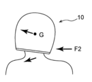
- the helmet when an impact is applied to the upper part of the helmet and near the top of the head, the helmet tries to rotate to the left around the center of gravity because the impact point is above the center of gravity of the helmet.
- the impact generates a force for rotating the helmet, that is, rotational acceleration.
- the lower end of the helmet hits the neck of the wearer, or the friction between the helmet and the road surface stops the rotation of the helmet.
- the rotational acceleration due to the impact is transmitted to the head of the wearer.
- the wearer fastens the pike, the wearer's head will also stop rotating at the same time as the helmet.
- the rotational acceleration is transmitted to the inside of the wearer's head, in the skull, the rotational force acts on the brain floating in the brain, and the axon connecting the brain and the inside of the skull is torn.
- the helmet according to the first aspect is a helmet comprising an outer cap body made of a hard material and a shock absorbing liner disposed inside the cap body, the shock absorbing liner comprising a body liner and the body liner A recess provided on the inner surface, an insert liner fitted in the recess, and a central support member disposed between the bottom of the recess and the bottom of the insert liner.
- the impact applied to the outer cap body is absorbed by deformation of the impact absorbing liner disposed inside the outer cap body.
- an insert liner is fitted in the recess of the main body liner.
- the center strut member is compressed and deformed by the impact, and the insert liner is inclined. That is, the insert liner moves relative to the main body liner.
- rotational acceleration does not propagate inside the head.
- a space exists in addition to the insert liner and the central support member. That is, the same effect as the conventional insert liner can be obtained by reducing the volume instead of reducing the density as in the conventional insert liner. In this way, not only the rotational acceleration of the wearer's head, but also the translational acceleration can be effectively reduced.
- the helmet of the second aspect is the helmet of the first aspect, wherein the shock absorbing liner comprises a plurality of other support members disposed around the central support member.
- the support members together with the central support member even if the wearer's head squeezes the insert liner when the wearer fastens. Since it supports the insert liner, it can be worn in a stable state without the insert liner being inclined and the helmet being shaken.
- the helmet of the third aspect is the helmet of the first aspect or the second aspect, wherein the central support member is integrally formed with the insert liner.
- the helmet of the third aspect by forming the central support member integrally with the insert liner, it is possible to suppress an increase in the number of components of the helmet.
- the helmet of the fourth aspect is the helmet according to the second aspect or the third aspect, wherein the cross-sectional area of the tip of the other strut member is smaller than the cross-sectional area of the tip of the central strut member, and the center
- the post member and the other post members are integrally formed with the insert liner.
- an increase in the number of components of the helmet can be suppressed by integrally forming the central support member and the other support members with the insert liner. Also, when an impact force is transmitted from the bottom of the recess to the central support member and the other support members, the other support members having a smaller contact area are deformed or broken earlier, so the central support member Can be completely destroyed by impact. In this manner, the insert liner can be reliably inclined by the central support member.
- the recess in the helmet according to any one of the first to fourth aspects, includes an air passage in communication with the air inlet in front of the helmet and an air passage in communication with the air outlet in back of the helmet.
- a passage is provided, and the insert liner is provided with an air passage connecting the recess and the inner surface of the main body liner (the surface in contact with the head of the wearer).
- the outside air taken in from the air inlet on the front of the helmet is led to the recess of the main body liner and further from the recess to the rear air outlet.
- the flow of air causes hot air emitted from the head of the wearer to be directed from the inner surface of the main body liner to the recess through the air passage of the insert liner. Also, the air from the recess enters the inner side surface of the main body liner. In this way, ventilation in the helmet can be performed well.
- the helmet of the sixth aspect is the helmet according to the fifth aspect, wherein the air inlet is an edge wrap member of the opening on the front surface of the helmet.
- the air inlet is used as the edge winding member of the opening on the front face of the helmet, so that the number of steps for providing the air inlet penetrating the cap can be eliminated, and It is possible to suppress an increase in the number of component parts.
- the helmet according to the present invention has an excellent effect that the rotational acceleration of the impact can be effectively reduced, and at the same time the translational acceleration can also be effectively reduced.
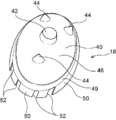
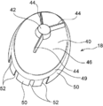
- FIG. 7 is a perspective view of the insert liner as viewed from the side opposite to the head of the user.
- FIG. 10 is a perspective view of another form of insert liner as viewed from the side opposite to the head of the user.
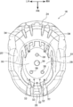
- FIG. 10 is a perspective view of another form of insert liner as viewed from the side opposite to the head of the user. It is a top view which shows the main body liner in which the insert liner was attached.
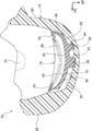
- FIG. 6 is a cross-sectional view showing an insert liner and a body liner cut along line 6-6 shown in FIG. 5; It is sectional drawing of a main body liner which shows ventilation inside the main body liner of this embodiment. It is the perspective view seen from the diagonally front side which shows the air inlet of the helmet of this embodiment. It is a front view showing the air inlet of the helmet of this embodiment.
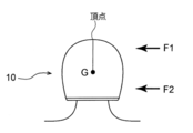
- production of rotational acceleration and is the figure which looked at the rider who wore the helmet before an impact is applied from back.
- production of rotational acceleration and is the figure which looked at the rider who wore the helmet at the time of an impact added from back.
- production of rotational acceleration and is the figure which looked at the rider who wore the helmet at the time of an impact added from back.
- the main body liner 16 with a recess 30 (see FIG. 3) described later at a position of 0 to 45 degrees with respect to a line segment connecting the center of gravity (G) and the vertex. Further, it is further preferable to provide the recess 30 at a position of 0 degrees to 20 degrees.
- FIGS. 1A to 6 The front in the front-rear direction as viewed from the wearer using the helmet is indicated by arrow FR, the right and left sides are indicated by arrow RH and arrow LH, and the upper side in the vertical direction is indicated by arrow UP. Moreover, in the following description, when showing the front-back, left-right, and up-down direction, it shall show front-back, left-right, up-down seen from the wearer of the state equipped with the helmet.
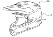
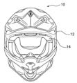
- the helmet 10 As shown in FIGS. 1A and 1B, the helmet 10 according to the present embodiment includes an outer cap 12 made of a hard material such as fiber reinforced resin, and the cap which is disposed inside the cap 12. And a shock absorbing liner 14 bonded to the inner surface of the housing 12.
- the shock absorbing liner 14 includes a body liner 16 and an insert liner 18 attached to the body liner 16. Furthermore, the body liner 16 is provided with a recess 30 for inserting the insert liner 18 therein.
- the main body liner 16 is formed using a synthetic resin foam, and the main body liner 16 is formed in a dome shape (concave shape) in which one side is opened. More specifically, the main body liner 16 is used by the left liner portion 20 and the right liner portion 22 disposed along the side of the user and the rear liner portion 24 disposed along the back of the user; And a front liner portion 26 disposed along the forehead of the person.
- the body liner 16 also includes an upper liner portion 28 disposed opposite to the top of the user's head.
- the upper liner portion 28 has an elliptical shape having a longitudinal direction as viewed in the front side of the main body liner 16 and a lateral direction as the lateral direction, and an insert liner 18 (see FIG. 2) described later is fitted therein.
- the recess 30 is formed.
- the recess 30 is formed with a vent 32 communicating with the front air inlet of the helmet 10 and a vent 34 communicating with the rear air outlet of the helmet 10.
- the central portion has a circular edge when viewed from the lower side and a central convex portion 42 (see FIG. 4B) of the insert liner 18 described later
- a recess 36 is formed at the central portion in the left-right direction and the front-rear direction of the concave portion 30, the central portion has a circular edge when viewed from the lower side and a central convex portion 42 (see FIG. 4B) of the insert liner 18 described later A recess 36 is formed.
- three peripheral recesses 38 in which three peripheral protrusions 44 (see FIG. 4B) of the insert liner 18 described later are respectively fitted are formed.
- two peripheral recess portions 38 spaced apart in the left and right direction are formed on the front side of the central recess portion 36, and one peripheral recess portion is formed in the lateral center portion on the rear side of the central recess portion 36. 38 are formed.
- the position of the recess 30 of the main body liner 16 is drawn when a line connecting the helmet 10 and the top of the helmet 10 (see FIGS. 8A to 8C) inclines the helmet 10 45 degrees around the center of gravity of the helmet 10. Is preferably in the shape of an oval formed by crossing the conical shape and the outer shell surface of the helmet 10, and more preferably in the 20 degree conical shape.
- the original thickness of the main body liner 16 is preferably 15 to 55 mm, and more preferably 35 to 45 mm.
- the depth of the recess 30 is preferably 35 mm or less, and more preferably 25 mm or less.
- the insert liner 18 is formed using a synthetic resin foam in the same manner as the body liner 16. Specifically, the insert liner 18 protrudes upward from the surface on the upper side of the insert liner main body 40 which is formed in a shallow dish shape (concave shape) in which one side is opened, and the upper surface of the insert liner main body 40. And a central protrusion 42 as a central support member and three peripheral protrusions 44 as other support members.
- the lower surface of the insert liner main body 40 is curved in a shape along the top of the user's head, and a plurality of grooves 48 for ventilation are formed.
- a thin portion 50 is disposed at the end of the outer periphery 49 of the insert liner main body 40.
- the thin portion 50 has a thickness smaller than that of the insert liner main portion 40, and is connected to the plurality of grooves 48, and has a plurality of cutouts 52 as a communicating portion having a substantially U-shaped edge as viewed from below. Is formed.
- the lower surface of the insert liner 18 (the surface that contacts the head of the wearer) has a symmetrical shape in the front-rear and left-right directions. In order to industrially manufacture, it is preferable that it is circular or elliptical shape.
- the central convex portion 42 is formed in a substantially cylindrical shape, and protrudes upward from the central portion in the front-rear direction and the central portion in the lateral direction of the upper surface of the insert liner main body portion 40. Further, the three peripheral protrusions 44 are formed in a substantially truncated cone shape having an outer diameter smaller than that of the central protrusion 42. In the present embodiment, two peripheral ridges 44 arranged at an interval in the lateral direction on the front side of the central ridge 42 are formed, and 1 in the lateral center of the central ridge 42 on the rear side. Three peripheral convex portions 44 are formed.
- the insert liner 18 preferably has a thickness of 5 mm or more, preferably 10 to 15 mm, from the lower surface (the surface facing the head of the wearer) to the bottom surface of the recess 30 of the main body liner 16. More preferable. Furthermore, the central projection 42 and the peripheral projection 44 prevent the insert liner 18 from being pushed and shaken by the head of the wearer when wearing the helmet. However, when an impact is applied to the vicinity of the crown of the helmet, first, the peripheral convex portion 44 is deformed, flexed or cracked by the impact force, but the central convex portion 42 centers the insert liner 18. As a result, a part of the insert liner 18 falls into the recess 30, and the opposite part is lifted.
- the peripheral projection 44 may have a conical tip as shown in FIG. 4C so that the contact area with the bottom of the recess 30 is smaller than that of the central projection 42. As shown in FIG. 4D, for example, like a great wall, it may be shaped like a wall (mountain ridge).
- the central convex portion 42 and the peripheral convex portion 44 preferably have a circular or elliptical cross-section with a diameter of 50 mm or less, and more preferably 30 mm or less.
- the insert liner 18 described above is attached (fixed) to the main body liner 16 in a state of being fitted into the recess 30 of the main body liner 16. More specifically, with the central projection 42 and the three peripheral projections 44 of the insert liner 18 engaged with the central recess 36 and the three peripheral recesses 38 of the main body liner 16, the insert liner 18 is engaged with the main body liner 16. It is fixed.
- the adhesive is interposed between the central convex portion 42 of the insert liner 18 and the central recess 36 of the main body liner 16 so that the insert liner 18 can be removed from the main body liner 16 even if the helmet is removed. It does not come off.
- a gap is formed between the upper surface of the insert liner main body 40 of the insert liner 18 and the main body liner 16.
- the gap formed between the outer periphery 49 of the insert liner 18 and the inner wall of the recess 30 is preferably 10 mm or less so that the insert liner 18 swings (swings and moves relative to the main body liner). And 3 mm to 7 mm are more preferable.
- central convex part 42 and three peripheral convex parts 44 of insert liner 18 into another member from insert liner 18 and body liner 16, for industrial manufacture, central convex part It is conceivable to integrally mold 42 and the three peripheral protrusions 44 on the bottom surface of the insert liner 18 or to integrally form on the bottom surface of the recess 30 of the main body liner 16.
- the thin portion 50 hides between the outer periphery 49 of the insert liner 18 and the inner wall of the recess 30, however, when the insert liner 18 swings, it is pressed against the inner wall of the recess 30 and is easily deformed or It does not disturb the swing as it is broken.
- the shock absorbing liner 14 disposed inside the outer cap 12 is deformed to the outer cap 12 by deformation.
- the applied impact is absorbed.
- the insert liner 18 is fitted in the recess 30 of the main body liner 16.
- the central protrusion 42 and the three peripheral protrusions 44 are deformed to reduce the translational acceleration, and the insert liner is moved (swinged) relative to the main body liner 16 to mount the helmet 10.
- the rotational acceleration of the head of the user can be effectively reduced.
- the phenomenon of ups and downs occurs (i.e., swings).
- the swinging of the insert liner 18 causes the head of the wearer in close contact with the insert liner 18 to swing and swing together. That is, even if the rotation of the helmet 10 is stopped after the rotational force is generated in the helmet 10 by the impact, the head of the wearer inside the helmet 10 continues to move, so the rotational acceleration due to the impact is propagated to the inside of the head Not or can be reduced.
- a helmet model 10 was placed on a human head model and dropped onto a steel anvil from a height of 2.5 m, and the rotational force generated by the impact was measured by an angular velocity meter.
- the impact points are three points near the top of the helmet 10, the forehead when the helmet 10 is tilted 45 degrees forward, and the left head when the helmet is tilted 45 degrees to the left.
- the rotational acceleration is clearly reduced as compared with the conventional insert liner.
- the conventional insert liner is of a type in which the insert liner does not swing relative to the main body liner.
- the insert liner 18 is stabilized by providing three peripheral convex portions 44 in addition to the central convex portion 42. Can be maintained.
- the force for supporting the insert liner 18 can be reinforced by providing three peripheral ridges 44 whose cross-sectional area of the tip is smaller than the central ridge 42 in addition to the central ridge 42. Then, translational acceleration can be buffered by deformation or refraction of any of the three peripheral protrusions 44, and rotational acceleration can also be buffered by the occurrence of a phenomenon of ups and downs of the insert liner 18.
- vent holes 32 and 34 as air passages communicating with the air inlet in front of the helmet 10 and the air outlet in back of the helmet 10.
- Each of the insert liners 18 is provided with a notch 52 communicating the recess 30 with the head of the wearer. External air taken in from the air inlet on the front of the helmet is introduced into the recess 30 through the vent 32 formed in the recess 30 of the body liner 16 and then discharged from the air outlet through the vent 34. A flow occurs. Therefore, the hot air emitted from the head of the wearer is guided to the recess of the main body liner through the notch 52 (communication portion).
- the ventilation performance in the helmet 10 can be improved. That is, the heat inside the helmet 10 can be exhausted to provide comfort to the wearer.
- the vent holes 32, 34 communicating with the front and back of the helmet 10 are provided at the top of the head including the recess 30, so that the main body liner 16 can more easily absorb the translational acceleration due to the impact.
- the notch 52 is provided as a communication portion for communicating the head of the wearer with the recess 30, but the present invention is not limited thereto, and a plurality of communication holes penetrating the insert liner 18 may be provided. Also good.
- a thin portion 50 whose thickness is set thinner than the thickness of the central portion 46 is disposed at the end of the outer periphery 49 of the insert liner main body 40.
- a plurality of cutouts 52 are formed in the thin portion 50. The notch 52 reduces the rigidity of the thin portion 50. As a result, the thin-walled portion 50 is easily deformed or broken when an impact is applied to the helmet 10, so that the insert liner does not interfere with the movement (swing).
- a plurality of peripheral convex portions 44 are arranged and reinforced around the central convex portion 42 so that the central convex portion 42 and the like are crushed and the insert liner 18 swings without being depressed in the concave portion 30. .
- an air inlet is provided on the edge winding member 54 at the opening on the front of the helmet, and the taken outside air is divided into two, one being the main body liner 16.
- the main body liner 16 Along the outer surface of the main body through the vent 32 to the recess 30 and the other one along the inner surface of the main body liner 16 to the vent groove 48 provided on the lower side of the insert liner 18 It is eaten. In this way, the number of parts for the air inlet can be reduced and the number of assembly steps can be reduced.
- the present invention is not limited to the above, and can be variously modified and carried out in addition to the above in the range which does not deviate from the main point. Of course.
Landscapes
- Helmets And Other Head Coverings (AREA)
Priority Applications (3)
| Application Number | Priority Date | Filing Date | Title |
|---|---|---|---|
| EP18806345.7A EP3636092B1 (en) | 2017-05-22 | 2018-03-05 | Helmet |
| CN201880033641.3A CN110785096B (zh) | 2017-05-22 | 2018-03-05 | 头盔 |
| US16/615,651 US11253021B2 (en) | 2017-05-22 | 2018-03-05 | Helmet |
Applications Claiming Priority (2)
| Application Number | Priority Date | Filing Date | Title |
|---|---|---|---|
| JP2017100732A JP6842991B2 (ja) | 2017-05-22 | 2017-05-22 | ヘルメット |
| JP2017-100732 | 2017-05-22 |
Publications (1)
| Publication Number | Publication Date |
|---|---|
| WO2018216306A1 true WO2018216306A1 (ja) | 2018-11-29 |
Family
ID=64395422
Family Applications (1)
| Application Number | Title | Priority Date | Filing Date |
|---|---|---|---|
| PCT/JP2018/008423 Ceased WO2018216306A1 (ja) | 2017-05-22 | 2018-03-05 | ヘルメット |
Country Status (5)
| Country | Link |
|---|---|
| US (1) | US11253021B2 (enExample) |
| EP (1) | EP3636092B1 (enExample) |
| JP (1) | JP6842991B2 (enExample) |
| CN (1) | CN110785096B (enExample) |
| WO (1) | WO2018216306A1 (enExample) |
Families Citing this family (19)
| Publication number | Priority date | Publication date | Assignee | Title |
|---|---|---|---|---|
| US20180235303A1 (en) * | 2014-02-21 | 2018-08-23 | Matscitechno Licensing Company | Helmet padding system |
| US11659882B2 (en) | 2014-02-21 | 2023-05-30 | Matscitechno Licensing Company | Helmet padding system |
| US11744312B2 (en) | 2014-02-21 | 2023-09-05 | Matscitechno Licensing Company | Helmet padding system |
| US11730222B2 (en) | 2014-02-21 | 2023-08-22 | Matscitechno Licensing Company | Helmet padding system |
| USD967543S1 (en) * | 2018-01-25 | 2022-10-18 | Bell Sports, Inc. | Helmet with integrated shoulder pad |
| USD908971S1 (en) * | 2018-07-20 | 2021-01-26 | Hjc Corp. | Helmet |
| USD949483S1 (en) * | 2019-08-05 | 2022-04-19 | H&H Sports Protection S.R.L. | Protective helmet |
| IT201900020410A1 (it) * | 2019-11-05 | 2021-05-05 | Kask Spa | Casco |
| US11540577B2 (en) | 2020-03-12 | 2023-01-03 | Matscitechno Licensing Company | Helmet system |
| US11540578B2 (en) | 2020-03-12 | 2023-01-03 | Matscitechno Licensing Company | Helmet system |
| USD977198S1 (en) * | 2020-06-23 | 2023-01-31 | Bell Sports, Inc. | Helmet |
| CN116709944A (zh) * | 2021-02-05 | 2023-09-05 | 株式会社 Shoei | 头盔及头盔的制造方法 |
| USD974704S1 (en) * | 2021-03-10 | 2023-01-10 | H&H Sports Protection S.R.L. | Helmet |
| USD1102040S1 (en) * | 2023-02-27 | 2025-11-11 | Fox Head, Inc. | Helmet |
| USD1115181S1 (en) * | 2023-05-10 | 2026-02-24 | Bell Sports, Inc. | Helmet with cheek pads |
| USD1094899S1 (en) | 2023-08-22 | 2025-09-23 | Liding Tang | Motorcycle helmet |
| USD1111320S1 (en) * | 2024-07-24 | 2026-02-10 | Henry Tedjakusuma | Helmet |
| JP1797075S (ja) | 2024-08-30 | 2025-04-24 | ヘルメット用バイザー | |
| CN223111130U (zh) * | 2024-10-22 | 2025-07-18 | 绍兴锐风运动用品有限公司 | 一种带鼻梁保护的头盔 |
Citations (3)
| Publication number | Priority date | Publication date | Assignee | Title |
|---|---|---|---|---|
| JPH09188913A (ja) * | 1995-10-30 | 1997-07-22 | Shoei Kako Kk | 安全用ヘルメットのための頭部保護体 |
| JP2001295129A (ja) * | 2000-04-04 | 2001-10-26 | Honda Motor Co Ltd | ヘルメット |
| US20170013907A1 (en) * | 2015-07-17 | 2017-01-19 | Anomaly Action Sports S.R.L. | Protective helmet |
Family Cites Families (15)
| Publication number | Priority date | Publication date | Assignee | Title |
|---|---|---|---|---|
| WO1991005489A1 (en) * | 1989-10-16 | 1991-05-02 | Rosebank Plastics Pty. Ltd. | Safety helmet and liner therefor |
| CA2089102C (en) | 1992-05-20 | 1996-12-17 | Haruo Tanaka | Ventilated vehicle helmet with modular duct forming lining |
| DE69634862T2 (de) | 1995-10-30 | 2006-05-11 | Shoei Co., Ltd. | Sicherheitshelm und Kopfschutzvorrichtung dafür |
| DE20007004U1 (de) * | 2000-04-15 | 2000-07-27 | Beck, Hans, 69412 Eberbach | Sturzhelm mit einer sich der Kopfform anpassenden Einlage |
| US20020174480A1 (en) * | 2001-05-25 | 2002-11-28 | Lombard Shoghi A. | Sports helmet and face guard |
| US7802320B2 (en) * | 2005-06-30 | 2010-09-28 | Morgan Don E | Helmet padding |
| KR101003670B1 (ko) | 2009-01-09 | 2010-12-23 | 고환복 | 헬멧 |
| EP2428129B1 (de) * | 2010-09-09 | 2013-04-03 | Oliver Schimpf | Schutzhelm; Verfahren zur Verminderung oder Verhinderung einer Kopfverletzung |
| CN103635112B (zh) * | 2011-02-09 | 2015-12-23 | 6D头盔有限责任公司 | 头盔全向能量管理系统 |
| US20140259316A1 (en) * | 2013-03-15 | 2014-09-18 | Barry H. Katz | Helmet system |
| JP6163366B2 (ja) * | 2013-06-27 | 2017-07-12 | 株式会社Shoei | ヘルメット |
| US10736373B2 (en) | 2013-08-13 | 2020-08-11 | Smith Optics, Inc. | Helmet with shock absorbing inserts |
| US10362829B2 (en) * | 2013-12-06 | 2019-07-30 | Bell Sports, Inc. | Multi-layer helmet and method for making the same |
| CN204742762U (zh) * | 2015-07-22 | 2015-11-11 | 宁波西博恩新材料科技有限公司 | 一种安全防护专用头盔 |
| EP3397101A4 (en) * | 2016-01-04 | 2019-08-28 | Bell Sports, Inc. | HELMET WITH BORDER TOP AND ELASTOMER BRACKETS |
-
2017
- 2017-05-22 JP JP2017100732A patent/JP6842991B2/ja active Active
-
2018
- 2018-03-05 EP EP18806345.7A patent/EP3636092B1/en active Active
- 2018-03-05 CN CN201880033641.3A patent/CN110785096B/zh active Active
- 2018-03-05 US US16/615,651 patent/US11253021B2/en active Active
- 2018-03-05 WO PCT/JP2018/008423 patent/WO2018216306A1/ja not_active Ceased
Patent Citations (4)
| Publication number | Priority date | Publication date | Assignee | Title |
|---|---|---|---|---|
| JPH09188913A (ja) * | 1995-10-30 | 1997-07-22 | Shoei Kako Kk | 安全用ヘルメットのための頭部保護体 |
| JP3825106B2 (ja) | 1995-10-30 | 2006-09-20 | 株式会社Shoei | 安全用ヘルメットのための頭部保護体 |
| JP2001295129A (ja) * | 2000-04-04 | 2001-10-26 | Honda Motor Co Ltd | ヘルメット |
| US20170013907A1 (en) * | 2015-07-17 | 2017-01-19 | Anomaly Action Sports S.R.L. | Protective helmet |
Non-Patent Citations (1)
| Title |
|---|
| See also references of EP3636092A4 |
Also Published As
| Publication number | Publication date |
|---|---|
| EP3636092A1 (en) | 2020-04-15 |
| US20200085131A1 (en) | 2020-03-19 |
| US11253021B2 (en) | 2022-02-22 |
| EP3636092B1 (en) | 2025-09-03 |
| EP3636092A4 (en) | 2021-03-17 |
| CN110785096A (zh) | 2020-02-11 |
| CN110785096B (zh) | 2022-06-14 |
| JP2018193654A (ja) | 2018-12-06 |
| JP6842991B2 (ja) | 2021-03-17 |
Similar Documents
| Publication | Publication Date | Title |
|---|---|---|
| JP6842991B2 (ja) | ヘルメット | |
| CA1222852A (en) | Crash helmet | |
| JP4059729B2 (ja) | 安全用ヘルメットのための頭部保護体 | |
| US11419381B2 (en) | Cranial protection cell | |
| US9681697B2 (en) | Helmet | |
| KR102207958B1 (ko) | 헬멧 | |
| JP2016023400A (ja) | 緩衝ヘルメット | |
| JP2018193654A5 (enExample) | ||
| CN112839538A (zh) | 用于撞击保护的头盔 | |
| CN108567192B (zh) | 安全头盔的全向防撞击结构 | |
| JP5591984B1 (ja) | ヘルメット | |
| US20200113266A1 (en) | Protective sports helmet | |
| US12279664B2 (en) | Protective helmet | |
| US20180242675A1 (en) | Helmet | |
| JP3825106B2 (ja) | 安全用ヘルメットのための頭部保護体 | |
| US20090300827A1 (en) | Device reducing wind noise | |
| JP2021147731A (ja) | ヘルメット | |
| JP3773606B2 (ja) | 安全用ヘルメットのための頭部保護体 | |
| JP6247143B2 (ja) | ヘルメット | |
| CN206659224U (zh) | 安全头盔的全向防撞击结构 | |
| JP2021147732A (ja) | ヘルメット | |
| KR101141935B1 (ko) | 머리 눌림이 개선된 안전모 | |
| JP6385877B2 (ja) | ヘルメット | |
| JP2018024974A (ja) | ヘルメット | |
| BR102016008113A2 (pt) | Improvements introduced in cranial protection cell |
Legal Events
| Date | Code | Title | Description |
|---|---|---|---|
| 121 | Ep: the epo has been informed by wipo that ep was designated in this application |
Ref document number: 18806345 Country of ref document: EP Kind code of ref document: A1 |
|
| NENP | Non-entry into the national phase |
Ref country code: DE |
|
| WWE | Wipo information: entry into national phase |
Ref document number: 2018806345 Country of ref document: EP |
|
| ENP | Entry into the national phase |
Ref document number: 2018806345 Country of ref document: EP Effective date: 20200102 |
|
| WWG | Wipo information: grant in national office |
Ref document number: 2018806345 Country of ref document: EP |