WO2018207901A1 - 車両の運転制御システム及び車両の運転制御方法 - Google Patents
車両の運転制御システム及び車両の運転制御方法 Download PDFInfo
- Publication number
- WO2018207901A1 WO2018207901A1 PCT/JP2018/018243 JP2018018243W WO2018207901A1 WO 2018207901 A1 WO2018207901 A1 WO 2018207901A1 JP 2018018243 W JP2018018243 W JP 2018018243W WO 2018207901 A1 WO2018207901 A1 WO 2018207901A1
- Authority
- WO
- WIPO (PCT)
- Prior art keywords
- vehicle
- driver
- stress tolerance
- driving
- driver assistance
- Prior art date
- Legal status (The legal status is an assumption and is not a legal conclusion. Google has not performed a legal analysis and makes no representation as to the accuracy of the status listed.)
- Ceased
Links
Images


Classifications
-
- B—PERFORMING OPERATIONS; TRANSPORTING
- B60—VEHICLES IN GENERAL
- B60W—CONJOINT CONTROL OF VEHICLE SUB-UNITS OF DIFFERENT TYPE OR DIFFERENT FUNCTION; CONTROL SYSTEMS SPECIALLY ADAPTED FOR HYBRID VEHICLES; ROAD VEHICLE DRIVE CONTROL SYSTEMS FOR PURPOSES NOT RELATED TO THE CONTROL OF A PARTICULAR SUB-UNIT
- B60W50/00—Details of control systems for road vehicle drive control not related to the control of a particular sub-unit, e.g. process diagnostic or vehicle driver interfaces
- B60W50/08—Interaction between the driver and the control system
-
- B—PERFORMING OPERATIONS; TRANSPORTING
- B60—VEHICLES IN GENERAL
- B60W—CONJOINT CONTROL OF VEHICLE SUB-UNITS OF DIFFERENT TYPE OR DIFFERENT FUNCTION; CONTROL SYSTEMS SPECIALLY ADAPTED FOR HYBRID VEHICLES; ROAD VEHICLE DRIVE CONTROL SYSTEMS FOR PURPOSES NOT RELATED TO THE CONTROL OF A PARTICULAR SUB-UNIT
- B60W30/00—Purposes of road vehicle drive control systems not related to the control of a particular sub-unit, e.g. of systems using conjoint control of vehicle sub-units
- B60W30/08—Active safety systems predicting or avoiding probable or impending collision or attempting to minimise its consequences
- B60W30/095—Predicting travel path or likelihood of collision
- B60W30/0953—Predicting travel path or likelihood of collision the prediction being responsive to vehicle dynamic parameters
-
- B—PERFORMING OPERATIONS; TRANSPORTING
- B60—VEHICLES IN GENERAL
- B60W—CONJOINT CONTROL OF VEHICLE SUB-UNITS OF DIFFERENT TYPE OR DIFFERENT FUNCTION; CONTROL SYSTEMS SPECIALLY ADAPTED FOR HYBRID VEHICLES; ROAD VEHICLE DRIVE CONTROL SYSTEMS FOR PURPOSES NOT RELATED TO THE CONTROL OF A PARTICULAR SUB-UNIT
- B60W30/00—Purposes of road vehicle drive control systems not related to the control of a particular sub-unit, e.g. of systems using conjoint control of vehicle sub-units
- B60W30/08—Active safety systems predicting or avoiding probable or impending collision or attempting to minimise its consequences
- B60W30/09—Taking automatic action to avoid collision, e.g. braking and steering
-
- B—PERFORMING OPERATIONS; TRANSPORTING
- B60—VEHICLES IN GENERAL
- B60W—CONJOINT CONTROL OF VEHICLE SUB-UNITS OF DIFFERENT TYPE OR DIFFERENT FUNCTION; CONTROL SYSTEMS SPECIALLY ADAPTED FOR HYBRID VEHICLES; ROAD VEHICLE DRIVE CONTROL SYSTEMS FOR PURPOSES NOT RELATED TO THE CONTROL OF A PARTICULAR SUB-UNIT
- B60W30/00—Purposes of road vehicle drive control systems not related to the control of a particular sub-unit, e.g. of systems using conjoint control of vehicle sub-units
- B60W30/08—Active safety systems predicting or avoiding probable or impending collision or attempting to minimise its consequences
- B60W30/095—Predicting travel path or likelihood of collision
- B60W30/0956—Predicting travel path or likelihood of collision the prediction being responsive to traffic or environmental parameters
-
- B—PERFORMING OPERATIONS; TRANSPORTING
- B60—VEHICLES IN GENERAL
- B60W—CONJOINT CONTROL OF VEHICLE SUB-UNITS OF DIFFERENT TYPE OR DIFFERENT FUNCTION; CONTROL SYSTEMS SPECIALLY ADAPTED FOR HYBRID VEHICLES; ROAD VEHICLE DRIVE CONTROL SYSTEMS FOR PURPOSES NOT RELATED TO THE CONTROL OF A PARTICULAR SUB-UNIT
- B60W30/00—Purposes of road vehicle drive control systems not related to the control of a particular sub-unit, e.g. of systems using conjoint control of vehicle sub-units
- B60W30/18—Propelling the vehicle
-
- B—PERFORMING OPERATIONS; TRANSPORTING
- B60—VEHICLES IN GENERAL
- B60W—CONJOINT CONTROL OF VEHICLE SUB-UNITS OF DIFFERENT TYPE OR DIFFERENT FUNCTION; CONTROL SYSTEMS SPECIALLY ADAPTED FOR HYBRID VEHICLES; ROAD VEHICLE DRIVE CONTROL SYSTEMS FOR PURPOSES NOT RELATED TO THE CONTROL OF A PARTICULAR SUB-UNIT
- B60W30/00—Purposes of road vehicle drive control systems not related to the control of a particular sub-unit, e.g. of systems using conjoint control of vehicle sub-units
- B60W30/18—Propelling the vehicle
- B60W30/182—Selecting between different operative modes, e.g. comfort and performance modes
-
- B—PERFORMING OPERATIONS; TRANSPORTING
- B60—VEHICLES IN GENERAL
- B60W—CONJOINT CONTROL OF VEHICLE SUB-UNITS OF DIFFERENT TYPE OR DIFFERENT FUNCTION; CONTROL SYSTEMS SPECIALLY ADAPTED FOR HYBRID VEHICLES; ROAD VEHICLE DRIVE CONTROL SYSTEMS FOR PURPOSES NOT RELATED TO THE CONTROL OF A PARTICULAR SUB-UNIT
- B60W40/00—Estimation or calculation of non-directly measurable driving parameters for road vehicle drive control systems not related to the control of a particular sub unit, e.g. by using mathematical models
- B60W40/08—Estimation or calculation of non-directly measurable driving parameters for road vehicle drive control systems not related to the control of a particular sub unit, e.g. by using mathematical models related to drivers or passengers
-
- G—PHYSICS
- G05—CONTROLLING; REGULATING
- G05D—SYSTEMS FOR CONTROLLING OR REGULATING NON-ELECTRIC VARIABLES
- G05D1/00—Control of position, course, altitude or attitude of land, water, air or space vehicles, e.g. using automatic pilots
- G05D1/0088—Control of position, course, altitude or attitude of land, water, air or space vehicles, e.g. using automatic pilots characterized by the autonomous decision making process, e.g. artificial intelligence, predefined behaviours
-
- G—PHYSICS
- G08—SIGNALLING
- G08G—TRAFFIC CONTROL SYSTEMS
- G08G1/00—Traffic control systems for road vehicles
- G08G1/16—Anti-collision systems
-
- B—PERFORMING OPERATIONS; TRANSPORTING
- B60—VEHICLES IN GENERAL
- B60W—CONJOINT CONTROL OF VEHICLE SUB-UNITS OF DIFFERENT TYPE OR DIFFERENT FUNCTION; CONTROL SYSTEMS SPECIALLY ADAPTED FOR HYBRID VEHICLES; ROAD VEHICLE DRIVE CONTROL SYSTEMS FOR PURPOSES NOT RELATED TO THE CONTROL OF A PARTICULAR SUB-UNIT
- B60W50/00—Details of control systems for road vehicle drive control not related to the control of a particular sub-unit, e.g. process diagnostic or vehicle driver interfaces
- B60W2050/0062—Adapting control system settings
- B60W2050/007—Switching between manual and automatic parameter input, and vice versa
- B60W2050/0071—Controller overrides driver automatically
-
- B—PERFORMING OPERATIONS; TRANSPORTING
- B60—VEHICLES IN GENERAL
- B60W—CONJOINT CONTROL OF VEHICLE SUB-UNITS OF DIFFERENT TYPE OR DIFFERENT FUNCTION; CONTROL SYSTEMS SPECIALLY ADAPTED FOR HYBRID VEHICLES; ROAD VEHICLE DRIVE CONTROL SYSTEMS FOR PURPOSES NOT RELATED TO THE CONTROL OF A PARTICULAR SUB-UNIT
- B60W2520/00—Input parameters relating to overall vehicle dynamics
- B60W2520/10—Longitudinal speed
-
- B—PERFORMING OPERATIONS; TRANSPORTING
- B60—VEHICLES IN GENERAL
- B60W—CONJOINT CONTROL OF VEHICLE SUB-UNITS OF DIFFERENT TYPE OR DIFFERENT FUNCTION; CONTROL SYSTEMS SPECIALLY ADAPTED FOR HYBRID VEHICLES; ROAD VEHICLE DRIVE CONTROL SYSTEMS FOR PURPOSES NOT RELATED TO THE CONTROL OF A PARTICULAR SUB-UNIT
- B60W2540/00—Input parameters relating to occupants
- B60W2540/22—Psychological state; Stress level or workload
-
- B—PERFORMING OPERATIONS; TRANSPORTING
- B60—VEHICLES IN GENERAL
- B60W—CONJOINT CONTROL OF VEHICLE SUB-UNITS OF DIFFERENT TYPE OR DIFFERENT FUNCTION; CONTROL SYSTEMS SPECIALLY ADAPTED FOR HYBRID VEHICLES; ROAD VEHICLE DRIVE CONTROL SYSTEMS FOR PURPOSES NOT RELATED TO THE CONTROL OF A PARTICULAR SUB-UNIT
- B60W2540/00—Input parameters relating to occupants
- B60W2540/221—Physiology, e.g. weight, heartbeat, health or special needs
-
- B—PERFORMING OPERATIONS; TRANSPORTING
- B60—VEHICLES IN GENERAL
- B60W—CONJOINT CONTROL OF VEHICLE SUB-UNITS OF DIFFERENT TYPE OR DIFFERENT FUNCTION; CONTROL SYSTEMS SPECIALLY ADAPTED FOR HYBRID VEHICLES; ROAD VEHICLE DRIVE CONTROL SYSTEMS FOR PURPOSES NOT RELATED TO THE CONTROL OF A PARTICULAR SUB-UNIT
- B60W2554/00—Input parameters relating to objects
-
- B—PERFORMING OPERATIONS; TRANSPORTING
- B60—VEHICLES IN GENERAL
- B60W—CONJOINT CONTROL OF VEHICLE SUB-UNITS OF DIFFERENT TYPE OR DIFFERENT FUNCTION; CONTROL SYSTEMS SPECIALLY ADAPTED FOR HYBRID VEHICLES; ROAD VEHICLE DRIVE CONTROL SYSTEMS FOR PURPOSES NOT RELATED TO THE CONTROL OF A PARTICULAR SUB-UNIT
- B60W2554/00—Input parameters relating to objects
- B60W2554/80—Spatial relation or speed relative to objects
- B60W2554/801—Lateral distance
Definitions
- the present disclosure relates to a vehicle operation control system and a vehicle operation control method.
- Patent Document 1 In recent years, research and development of technology for automatically driving a vehicle by an operation control system mounted on a car is being carried out regardless of the operation of the driver (see, for example, Patent Document 1).
- An object of the present disclosure is to provide a vehicle driving control system and a vehicle driving control method capable of safely and quickly transferring vehicle driving authority from a driving control system to a driver. There is to do.
- a vehicle operation control system includes a function for automatically driving a vehicle.
- the control device for controlling the operation control system includes the vehicle.
- a stress tolerance judging means for judging the stress tolerance of the driver, a stress tolerance memory means for memorizing the stress tolerance judged by the stress tolerance judging means, and forcing the driver to manually run during the automatic running of the vehicle
- An operation switching determination unit that determines whether or not it is necessary to switch, and a stress tolerance stored in the stress tolerance storage unit when the operation switching determination unit determines that switching from automatic traveling to manual traveling is necessary
- Driver assistance type selection means for selecting a driver assistance type based on the driver assistance type and driver assistance type selected by this driver assistance type selection means. Based on the format constituted by a driver assistance execution means for performing driver assistance when switching forced to manual driving from the automatic traveling of the vehicle.
- the vehicle operation control method of the present disclosure for achieving the above object is a vehicle operation control method configured to have a function of automatically driving the vehicle, wherein the stress resistance of the driver of the vehicle is determined in advance.
- a driver assistance type is selected based on the pre-determined driver's stress tolerance, and this selection is performed.
- driver assistance is performed when switching from automatic traveling to manual traveling of the vehicle.
- the driver assistance format (content) that the system performs when the driving authority is delegated for example, the system
- the volume, frequency, or content of an alarm including information that prompts the driver to switch from manual driving to manual driving is set based on the driver's stress tolerance.
- FIG. 1 is a diagram illustrating a configuration of a vehicle operation control system according to the present disclosure.
- FIG. 2 is a diagram exemplifying the timing of the start of driving switching alarm and the start of automatic braking based on the distance between the host vehicle and the vehicle ahead. Section (a) in FIG. 2 shows a state where the host vehicle is traveling automatically. Section (b) in FIG. 2 shows the timing for starting the operation switching warning of the host vehicle. Section (c) in FIG. 2 shows the timing of the start of automatic braking of the host vehicle.
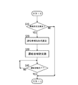
- FIG. 3 is a diagram illustrating a control flow of the vehicle operation control method of the present disclosure.
- the vehicle 3 including the vehicle driving control system 1 is configured to include an automatic traveling function that allows the driving control system 1 to automatically drive the vehicle 3 to travel without depending on the driving operation of the driver. That is, the automatic traveling function is a function in which the driving control system 1 performs a vehicle speed control operation (depressing an accelerator pedal or a brake pedal) and a steering control operation (handle operation) performed by the driver instead. Therefore, either the driver or the driving control system 1 has driving authority for the vehicle 3. Further, the vehicle 3 includes a control device 2 that controls the operation control system 1.
- the control device 2 includes a stress tolerance determination unit 2 a, a stress tolerance storage unit 2 b, a driving switching determination unit 2 c, a driver assistance type selection unit 2 d, and a driver assistance execution unit 2 e. Constructed with one means.
- the stress tolerance determination means 2a is a means for measuring and determining the stress tolerance X of the driver of the vehicle 3.
- the driver's stress tolerance means how easily the driver can panic against sudden situations such as sudden danger of colliding with an obstacle such as a vehicle traveling in front of the vehicle 3 regardless of physical condition. It is an index showing.
- the driver's stress tolerance X is determined to be lower.
- the determination result of the stress tolerance X may be two levels of high or low, three levels of high, normal or low, or four or more levels. Further, the stress tolerance X based on the heart rate may be measured only once. However, it is preferable to perform the stress tolerance X more than once and determine the stress tolerance X using the average value of the measurement results of the plurality of times. The determination accuracy of the tolerance X can be improved, which is more preferable.
- the stress tolerance determination means 2a stores a plurality of questions (about several tens of questions) related to the driver characteristics in the stress tolerance determination means 2a in advance, and the driver's answer contents to the questions extracted from the stored plurality of questions. Based on this, the driver's stress tolerance X may be measured and determined.
- the question to the driver is an alternative, and is made by voice from a voice device provided in the driver's seat at the start of the vehicle or during steady running, or by text displayed on a text display panel. The driver's answer to the question is made verbally or by operating a handle switch.
- the control time set in advance from the time when the question was asked without obtaining a response from the driver.
- the time elapses for example, about 30 seconds to 1 minute
- the question is canceled.
- the control for obtaining the answer to the question is performed while giving the highest priority to the driving operation of the driver, so that the answer speed of the driver to the question does not affect the measurement and determination of the stress tolerance X of the driver.
- the number of questions to the driver may be one, but a plurality of questions is more preferable because the determination accuracy of the stress tolerance X can be improved.
- the stress tolerance determination means 2a may measure and determine the stress tolerance X using both the heart rate increase degree ⁇ HR and the numerical value AC based on the response content.
- the magnitudes of the weighting coefficients ⁇ and ⁇ are preferably determined based on experimentally verified results.
- the stress tolerance determination unit 2a is configured as a unit that determines the stress tolerance of the driver based on the heart rate of the driver or the answer content to the question from the stress tolerance determination unit 2a.
- the driver's stress tolerance X can be measured and determined with high accuracy.
- the stress tolerance storage means 2b is means for storing the stress tolerance X determined by the stress tolerance determination means 2a. Further, the driving switching determination means 2c determines whether or not it is necessary to forcibly switch to manual driving by the driver during the automatic driving of the vehicle 3 by the driving control system 1 as shown in FIG. That is, it is means for determining whether or not it is necessary to forcibly delegate the driving authority of the vehicle 3 from the driving control system 1 to the driver.
- the collision allowance time t until the host vehicle 3 collides with an obstacle 4 positioned in front of the host vehicle 3 during the automatic traveling of the host vehicle 3 is equal to or less than a preset set time threshold t1.
- a distance d between the host vehicle 3 and the obstacle 4 is set in advance according to the speed (vehicle speed) of the host vehicle 3 as shown in FIG.
- the running mode of the own vehicle 3 is switched from automatic running to manual running. Judge that it is necessary.
- the distance d is detected by using a radar or a camera for detecting the inter-vehicle distance installed in the host vehicle 3.
- the collision margin time t is calculated by calculating the relative speed of the host vehicle 3 with respect to the obstacle 4 from the continuous change of the detected value of the distance d, and using the calculated value of the relative speed and the detected value of the distance d.
- the obstacle 4 is installed in front of a traveling lane in which the host vehicle 3 travels due to a vehicle traveling in front of the traveling lane in which the host vehicle 3 travels or a landslide in front of the host vehicle 3. Fallen rocks.
- the driver assistance format selection means 2d is a driver assistance format based on the stress tolerance X stored in the stress tolerance storage means 2b when it is determined by the driving switching judgment means 2c that switching from automatic running to manual running is necessary. It is a means to select.
- the driver assistance format selection means 2d stores a driver assistance format based on the stress tolerance X in advance.
- the driver assistance format is configured as a format for providing information to encourage manual driving by the driver. More specifically, the driver assistance format is a volume, frequency, or content format of an alarm including information that prompts the driver to switch from automatic driving to manual driving by the driving control system 1. For example, when the determination of stress tolerance X is performed in two stages, high or low, and for a driver with high stress resistance X, the alarm volume is set to a large value and the frequency is set high so that the driver has a moderate urgency. In addition, without instructing detailed driving operations, it is set to a format that informs the driver only that switching from automatic driving to manual driving is necessary, such as “Please switch from automatic driving to manual driving”.
- the warning format for the driver having high stress tolerance X is preferably set to a volume, frequency, or content format that is comparable to a warning that has been conventionally given to the driver.
- the alarm volume is set low and the frequency is set low for the driver as compared with an alarm that is issued to a driver having high stress tolerance X. Instruct the driver to perform detailed driving operations such as "please step on the brake pedal" or "steer to the right to change the driving lane".
- Set to format
- the alarm volume is set lower and the frequency is lowered as the stress tolerance X becomes lower, and the driver is informed of the information in a soft expression. And the information content is also simplified. Also in this case, it is preferable that the type of the alarm at the stage where the stress tolerance X is the highest is a volume, frequency or content of the same level as the alarm conventionally given to the driver.
- the driver is provided with information necessary for switching from automatic driving by the driving control system 1 to manual driving by the driver without causing the driver to panic. It can be transmitted reliably.
- Driver assistance execution means 2e is means for performing driver assistance when forcibly switching the vehicle 3 from automatic traveling to manual traveling based on the driver assistance format selected by the driver assistance format selection means 2d.
- a voice device or a text display panel provided in the driver's seat corresponds to the means 2e.
- the driving authority of the vehicle 3 is completely switched from the driving control system 1 to the driver. Whether or not the driver has suddenly braked is determined based on whether or not the reduction amount per unit time of the acceleration sensor installed in the vehicle 3 is larger than a preset reduction amount. The determination as to whether or not the driver steered suddenly is made based on whether or not the fluctuation amount per unit time of the steering angle sensor installed in the vehicle 3 is larger than a preset fluctuation amount.
- the vehicle control system 1 slowly decelerates the vehicle 3 or slowly after the alarm is started by the driver assistance execution means 2e until the driver operates in response to the alarm. You may perform control which adjusts a steering angle. By performing such control, the driver can know the driving operation necessary for switching the driving from the automatic driving to the manual driving.
- a second set time in which the collision allowance time t until the own vehicle 3 collides with the obstacle 4 is set as a value smaller than the set time threshold value t1 while the warning is issued by the driver assistance execution unit 2e.
- the second distance d between the host vehicle 3 and the obstacle 4 is preset as a value smaller than the set distance threshold d1.
- the distance becomes equal to or smaller than the set distance threshold d1 automatic braking for forcibly stopping the host vehicle 3 before the obstacle 4 is started by the driving control system 1 regardless of the operation of the driver.
- the driving control system 1 forcibly stops the host vehicle 3 before the falling rock 4 without prompting the driver to switch from automatic driving to manual driving of the vehicle. To start automatic braking. By doing in this way, the collision of the own vehicle 3 and the obstruction 4 can be avoided, without giving an excessive driving
- the control flow of FIG. 3 is a control flow called from the advanced control flow every time a preset control time elapses during automatic traveling of the vehicle.
- a sudden situation such as a sudden deceleration of the vehicle 4 traveling in front of the traveling lane on which the host vehicle 3 travels has occurred. If no unexpected situation has occurred (NO), the process proceeds to return, and this control flow ends.
- step S20 if a sudden situation occurs (YES), the process proceeds to step S20, and a driver assistance format based on the stress tolerance X stored in advance in the stress tolerance storage means 2b in step S20 is selected. After performing the control of step S20, the process proceeds to step S30.
- step S30 based on the driver assistance format selected in step S20, the driver assistance necessary for forcibly switching the vehicle 3 from automatic traveling to manual traveling is performed, and the driving authority of the vehicle 3 is driven. Delegate from the control system 1 to the driver. After performing the control of step S30, the process proceeds to step S40.
- step S ⁇ b> 40 it is determined whether or not the driving switching from the automatic driving by the driving control system 1 of the host vehicle 3 to the manual driving by the driver is completed by the driver performing sudden braking or steering. . If the operation switching has not been completed (NO), the determination in step S40 is performed again after the preset control time has elapsed. On the other hand, when the operation switching has been completed (YES), the process proceeds to return, and this control flow ends.
- the vehicle driving control method based on the vehicle driving control system 1 is a vehicle driving control method configured to have a function of automatically driving the vehicle.
- X is determined in advance, and when it is necessary to forcibly switch to manual driving by the driver during the automatic driving of the vehicle 3, a driver assistance type is selected based on the stress tolerance X of the driver determined in advance.
- driver assistance is performed when the vehicle 3 is switched from automatic travel to manual travel.
- the driver's stress tolerance X is stored in the stress tolerance storage unit 2b in advance.
- the driver's stress tolerance X is not stored in the stress tolerance storage unit 2b.
- the driver assistance format selected when the stress tolerance X is low is assumed assuming that the driver's stress tolerance X is low. Based on the driver assistance.
- the stress tolerance storage means 2b stores the stress tolerance for each driver, and the driving authority of the vehicle 3 is given.
- the driver assistance type based on the stress tolerance of each driver stored in the stress tolerance storage means 2b is selected by the driver assistance type selection means 2d.
- the determination of the driver of the vehicle 3 may be performed based on, for example, the distribution of the weight of the driver added to the seat surface of the driver seat when the driver is seated in the driver seat, or by a camera installed in the vehicle.
- a method for detecting and authenticating a face may be used, or a license or an employee ID card in which personal information is registered may be inserted into a card reader for determination.
- the functions realized by the control device 2 are stress tolerance determination means 2a, stress tolerance storage means 2b, operation switching determination means 2c, and driver.
- the description is divided into five means, that is, auxiliary type selection means 2d and driver auxiliary execution means 2e.
- the control device 2 may be specifically realized by the following configuration, for example. That is, the control device 2 is connected to various devices provided in the vehicle 3 by wireless or wired, and transmits and receives signals for communicating with the various devices, a memory for storing information, and a controller. It can be prepared.
- an operation unit such as a button, a switch, and a touch panel operated by a driver or an occupant of the vehicle 3, a display for displaying a screen, a speaker for outputting sound, and a voice command by the driver or occupant are received. It includes a microphone, a heart rate measurement sensor that measures the heart rate of the driver, an in-vehicle camera that images and monitors the driving state of the driver, and the like.
- Examples of the various devices include various actuators for controlling the traveling state of the vehicle 3, a brake system for the vehicle 3, an engine control system for the vehicle 3, lights provided in the vehicle 3, a rear lamp, a hazard lamp, and the like.
- a lighting device, a vehicle speed sensor that measures the vehicle speed of the vehicle 3, an acceleration sensor and an impact sensor that measure acceleration and impact generated in the vehicle 3, a steering angle sensor that measures the steering angle of the vehicle 3, and a traveling environment of the vehicle 3 are detected. Including a traveling camera or radar, etc.
- the interface includes a communication module for performing communication with various devices.
- a communication module for performing communication with various devices.
- the interface may be connected to various devices by wire, or by including a wireless communication module, for example. It may be connected to various devices wirelessly.
- the memory may include a semiconductor storage device such as a rewritable DRAM or EPROM, or a non-rewritable ROM, or may include a storage device such as a hard disk.
- a semiconductor storage device such as a rewritable DRAM or EPROM, or a non-rewritable ROM, or may include a storage device such as a hard disk.
- the controller is connected to the interface and memory.
- the controller may be configured by, for example, a processor and configured to execute a series of processes by executing a program stored in a memory.
- the controller is configured as hardware such as an ASIC and is predetermined. You may be comprised so that a series of processes may be performed.
- the controller determines the stress tolerance of the driver of the vehicle 3 based on the signal exchanged by the interface, stores a stress tolerance value indicating the determined level of stress tolerance in the memory, and based on the signal exchanged by the interface. Thus, it is determined whether it is necessary to forcibly switch to manual driving by the driver while the vehicle 3 is performing automatic driving, and it is determined that it is necessary to forcibly switch from automatic driving to manual driving. Accordingly, a driver assistance format corresponding to the stress tolerance value stored in the memory is selected from a plurality of driver assistance formats registered in advance, and an interface is selected based on the selected driver assistance format. By controlling the device via the vehicle driver assistance is provided when the vehicle 3 is forcibly switched from automatic travel to manual travel.
Landscapes
- Engineering & Computer Science (AREA)
- Automation & Control Theory (AREA)
- Mechanical Engineering (AREA)
- Transportation (AREA)
- Physics & Mathematics (AREA)
- General Physics & Mathematics (AREA)
- Evolutionary Computation (AREA)
- Aviation & Aerospace Engineering (AREA)
- Radar, Positioning & Navigation (AREA)
- Remote Sensing (AREA)
- Medical Informatics (AREA)
- Game Theory and Decision Science (AREA)
- Business, Economics & Management (AREA)
- Human Computer Interaction (AREA)
- Artificial Intelligence (AREA)
- Health & Medical Sciences (AREA)
- Mathematical Physics (AREA)
- Traffic Control Systems (AREA)
- Control Of Driving Devices And Active Controlling Of Vehicle (AREA)
Abstract
車両の運転者のストレス耐性Xを予め判定しておき、車両の自動走行中に運転者による手動走行に強制的に切り替える必要があるときに、この予め判定した運転者のストレス耐性Xを基に運転者補助形式を選定するとともに、この選定した運転者補助形式に基づいて、車両の自動走行から手動走行に切り替える際の運転者補助を行う。
Description
本開示は、車両の運転制御システム及び車両の運転制御方法に関する。
近年、運転者の操作に依らず、自動車に搭載された運転制御システムにより車両を自動運転する技術の研究開発が進められている(例えば、特許文献1参照)。
ところで、車両をシステム側で自動運転して走行(自動走行)させているときで、自車両の前方を走行する車両が急減速したり、または、自車両の前方に落石等が発生したりして、自車両が前方の車両や落石等の障害物に衝突する危険が生じる可能性がある。このような突発的な状況が発生したときには、車両の運転権限をシステムから運転者に強制的に委譲する必要がある。この運転権限の委譲を行う際には、システムによる自動運転から運転者による手動運転への運転切替を促す情報を含む警報を発報する。
しかしながら、運転者が突発的な状況に対して比較的慌て易い性格である場合、言い換えれば、運転者のストレス耐性が低い場合には、過剰に切迫感を煽るような警報を発報すると、運転者がパニックに陥り、車両の運転権限をシステムから運転者に安全かつ迅速に委譲することが困難になる虞がある。
本開示の目的は、車両の運転権限を運転制御システムから運転者に強制的に委譲する必要がある場合に安全かつ迅速に委譲することができる車両の運転制御システム及び車両の運転制御方法を提供することにある。
上記の目的を達成するための本開示の車両の運転制御システムは、車両を自動走行させる機能を備えて構成される車両の運転制御システムにおいて、この運転制御システムを制御する制御装置が、前記車両の運転者のストレス耐性を判定するストレス耐性判定手段と、このストレス耐性判定手段により判定したストレス耐性を記憶するストレス耐性記憶手段と、前記車両の自動走行中に運転者による手動走行に強制的に切り替える必要があるか否かを判定する運転切替判定手段と、この運転切替判定手段で自動走行から手動走行への切替が必要であると判定したときに、前記ストレス耐性記憶手段に記憶したストレス耐性に基づく運転者補助形式を選定する運転者補助形式選定手段と、この運転者補助形式選定手段により選定した運転者補助形式に基づいて、前記車両の自動走行から手動走行に強制的に切り替える際の運転者補助を行う運転者補助実施手段とを備えて構成される。
また、上記の目的を達成するための本開示の車両の運転制御方法は、車両を自動走行させる機能を備えて構成される車両の運転制御方法において、前記車両の運転者のストレス耐性を予め判定しておき、前記車両の自動走行中に運転者による手動走行に強制的に切り替える必要があるときに、この予め判定した運転者のストレス耐性を基に運転者補助形式を選定するとともに、この選定した運転者補助形式に基づいて、前記車両の自動走行から手動走行に切り替える際の運転者補助を行うことを特徴とする方法である。
本開示では、車両の運転権限を運転制御システム(制御装置)から運転者に強制的に委譲する必要があるときに、運転権限の委譲時にシステムが行う運転者補助形式(内容)、例えば、システムによる自動運転から運転者による手動運転への運転切替を促す情報を含む警報の音量、周波数または内容を運転者のストレス耐性に基づいて設定する。
これにより、ストレス耐性の低い運転者が過剰に切迫感を煽る警報を受けてパニックに陥るのを回避することができる。その結果、車両の運転権限を運転制御システムから運転者に強制的に委譲する必要がある場合に安全かつ迅速に委譲することができる。
以下、本開示の車両の運転制御システム及び車両の運転制御方法について図に示した実施形態に基づいて説明する。なお、本開示の車両の運転制御システム1を備える車両3は、運転者の運転操作に依らず、運転制御システム1が車両3を自動運転して走行させる自動走行機能を備えて構成する。すなわち、自動走行機能とは、運転者が行う車速制御操作(アクセルペダルまたはブレーキペダルの踏込)及び操舵制御操作(ハンドル操作)を運転制御システム1が代わりに行う機能である。したがって、車両3の運転権限は、運転者または運転制御システム1のいずれか一方が有することとなる。また、車両3には、運転制御システム1を制御する制御装置2が備わる。
本開示では、図1に示すように、制御装置2が、ストレス耐性判定手段2a、ストレス耐性記憶手段2b、運転切替判定手段2c、運転者補助形式選定手段2d及び運転者補助実施手段2eの5つの手段を備えて構成される。
ストレス耐性判定手段2aは、車両3の運転者のストレス耐性Xを測定及び判定する手段である。運転者のストレス耐性とは、自車両3が前方を走行する車両等の障害物に衝突する危険が突然生じる等の突発的な状況に対して運転者が体調に依らず本来どの程度慌てやすいのかを示す指標である。
ストレス耐性判定手段2aは、例えば、車両3の運転席に備えた心拍数測定センサ等により検出される運転者の心拍数に基づいてストレス耐性Xを測定及び判定する。より詳細には、運転者が車両を手動運転しているときで急ブレーキをかけたりまたは急ハンドルを切ったりしたときに、運転者の心拍数が通常の運転時の心拍数よりどの程度上昇したか、この上昇度合いΔHRに基づいてストレス耐性Xを測定する。ストレス耐性Xは心拍数の上昇度合いΔHRと同じ値(X=ΔHR)とすると、制御が簡素化されてよい。そして、測定したストレス耐性Xと予め設定した設定閾値を比較することで、運転者のストレス耐性Xが高いか低いかを判定する。心拍数の上昇度合いΔHRが大きいほど、運転者のストレス耐性Xはより低い方向に判定される。なお、ストレス耐性Xの判定結果は、高いまたは低いの2段階でもよいし、高い、普通または低いの3段階でもよいし、4段階以上でもよい。また、この心拍数に基づくストレス耐性Xの測定は1回行うだけでもよいが、複数回行ってこの複数回の測定結果の平均値を用いてストレス耐性Xの判定を行う方が運転者のストレス耐性Xの判定精度を向上させることができるのでより好ましい。
ストレス耐性判定手段2aは、運転者特性に関わる質問を複数(数十程度)予めストレス耐性判定手段2aに記憶させておき、この記憶させた複数の質問から抽出した質問に対する運転者の回答内容に基づいて運転者のストレス耐性Xを測定及び判定してもよい。運転者への質問は、択一式で、車両の始動時や定常走行時等に運転席に備えた音声装置からの音声またはテキスト表示パネルに表示されるテキスト等により行う。質問への運転者の回答は、口頭またはハンドルスイッチ操作等により行う。また、運転者が急な運転操作を行う必要がある等により質問に回答するのが困難な場合も考えられるので、運転者からの回答を得ることなく質問を行った時点から予め設定した制御時間(例えば、30秒~1分程度)経過したときには、質問をキャンセルする。このように運転者の運転操作を最優先させながら質問に対する回答を求める制御を行うので、運転者のストレス耐性Xの測定及び判定には質問に対する運転者の回答速度は影響を与えないようにする。なお、運転者への質問数は1個でもよいが、複数個の方がストレス耐性Xの判定精度を向上させることができるのでより好ましい。
質問の各選択肢には数値が設定され、運転者の回答した選択肢の数値の合計値ACに基づいてストレス耐性Xは測定される。ストレス耐性Xは運転者の回答内容に基づく数値ACと同じ値(X=AC)とすると、制御が簡素化されてよい。そして、測定したストレス耐性Xと予め設定した設定閾値を比較することで、運転者のストレス耐性Xが高いか低いかを判定する。合計値ACが大きいほど、運転者のストレス耐性Xはより低い方向に判定される。ストレス耐性Xの判定結果は、心拍数に基づくストレス耐性Xの判定の場合と同様に、2段階でも、3段階でも、4段階以上でもよい。
ストレス耐性判定手段2aは、心拍数の上昇度合いΔHRと回答内容に基づく数値ACの両方を用いてストレス耐性Xを測定及び判定してもよい。この場合、ストレス耐性Xは、例えば、重み付け係数をα及びβとして、X=α×ΔHR+β×ACの線形計算式を用いて算出(測定)することとなる。重み付け係数α、βの大小については、実験的に検証した結果を踏まえて決定するのが望ましい。
以上のように、ストレス耐性判定手段2aを、運転者の心拍数またはストレス耐性判定手段2aから運転者への質問に対する回答内容に基づいて運転者のストレス耐性を判定する手段として構成することで、運転者のストレス耐性Xを高精度で測定及び判定することができる。
ストレス耐性記憶手段2bは、ストレス耐性判定手段2aにより判定したストレス耐性Xを記憶する手段である。また、運転切替判定手段2cは、図2(a)に示すような運転制御システム1による車両3の自動走行中に運転者による手動走行に強制的に切り替える必要があるか否かを判定する手段、すなわち、車両3の運転権限を運転制御システム1から運転者に強制的に委譲する必要があるか否かを判定する手段である。
より詳細には、自車両3の自動走行中で、自車両3の前方に位置する障害物4に自車両3が衝突するまでの衝突余裕時間tが予め設定された設定時間閾値t1以下となったときに、または、図2(b)に示すように、自車両3と障害物4との間の距離dが、自車両3の速度(車速)に応じて予め設定された設定距離閾値d1以下となったときには、自車両3の自動走行を継続すると自車両3が障害物4と衝突する虞があるため、これを回避すべく、自車両3の走行形態を自動走行から手動走行に切り替える必要があると判定する。距離dは、自車両3に設置した車間距離検出用のレーダーまたはカメラを用いて検出される。衝突余裕時間tは、距離dの検出値の連続的変化より障害物4に対する自車両3の相対速度を算出して、この相対速度の算出値と距離dの検出値を用いて算出される。なお、障害物4は、自車両3の走行する走行車線の前方を走行する車両や、自車両3の前方での崖崩れの発生に起因して自車両3の走行する走行車線の前方に設置される落石等である。
このように、衝突余裕時間tまたは距離dに応じて車両3の運転権限を運転制御システム1から運転者に強制的に委譲する必要があるか否かを判定することで、自車両3が障害物4と衝突する虞があるときのみ、運転権限の委譲が必要であると判定することができるので、運転者の無駄な運転負担の増加を抑制することができる。
運転者補助形式選定手段2dは、運転切替判定手段2cで自動走行から手動走行への切替が必要であると判定したときに、ストレス耐性記憶手段2bに記憶したストレス耐性Xに基づく運転者補助形式を選定する手段である。運転者補助形式選定手段2dには、予めストレス耐性Xに基づく運転者補助形式を記憶しておく。
運転者補助形式は、運転者による手動走行を促すための情報の提供形式として構成する。より詳細には、運転者補助形式は、運転制御システム1による自動運転から運転者による手動運転への運転切替を促す情報を含む警報の音量、周波数または内容の形式である。例えば、ストレス耐性Xの判定を高いまたは低いの2段階で行う場合、ストレス耐性Xが高い運転者の場合には、警報の音量を大きく周波数を高く設定して運転者に対して適度に切迫感を煽るとともに、細かな運転操作を指示することなく、「自動運転から手動運転に切り替えて下さい」等、自動運転から手動運転への切替が必要なことのみ運転者に連絡する形式に設定する。このストレス耐性Xが高い運転者に対する警報の形式は、運転者に対して従来行っていた警報と同程度の音量、周波数または内容の形式とすることが好ましい。一方、ストレス耐性Xの判定が低い運転者の場合には、ストレス耐性Xが高い運転者に対して発報する警報と比較して、警報の音量を小さく周波数を低く設定して運転者に対して過剰に切迫感を煽ることがないようにするとともに、「ブレーキペダルを踏んで下さい」や「右に操舵して走行車線を変更して下さい」等、細かな運転操作を運転者に指示する形式に設定する。
なお、ストレス耐性Xの判定を3段階以上で行う場合は、ストレス耐性Xが低い段階となるにつれて警報の音量を小さく周波数を低く設定するとともに、運転者に対して柔らかな表現で情報を連絡し、かつ、その情報内容も簡素化する。この場合も、ストレス耐性Xが最も高い段階の警報の形式は、運転者に対して従来行っていた警報と同程度の音量、周波数または内容の形式とすることが好ましい。
このように運転者補助形式を選定することで、運転者がパニックに陥ることなく、運転制御システム1による自動運転走行から運転者による手動運転走行に切り替える際に必要な情報を運転者に対して確実に伝達することができる。
運転者補助実施手段2eは、運転者補助形式選定手段2dにより選定した運転者補助形式に基づいて、車両3の自動走行から手動走行に強制的に切り替える際の運転者補助を行う手段である。例えば、運転席に備えた音声装置やテキスト表示パネル等がこの手段2eに該当する。運転切替判定手段2cにより車両3の自動走行から手動走行に切り替える必要があると判定して、運転者補助形式選定手段2dにより運転者のストレス耐性Xに基づく運転者補助形式が選定された後、運転者補助実施手段2eにより運転者補助形式選定手段2dで選定された運転者補助形式に対応する警報を発報する。
以上より、本開示によれば、ストレス耐性の低い運転者が過剰に切迫感を煽る警報を受けてパニックに陥るのを回避することができる。その結果、車両3の運転権限を運転制御システム1から運転者に強制的に委譲する必要がある場合に安全かつ迅速に委譲することができる。
なお、運転者補助実施手段2eによる警報の発報中に、運転者が急ブレーキまたは急操舵を行ったときに、車両3の運転権限は運転制御システム1から運転者に完全に切り替わる。運転者が急ブレーキを行ったか否かの判定は、車両3に設置された加速度センサの単位時間あたりの減少量が予め設定された設定減少量より大きいか否かで行う。運転者が急操舵を行ったか否かの判定は、車両3に設置された操舵角センサの単位時間当たりの変動量が予め設定された設定変動量より大きいか否かで行う。
また、運転者補助実施手段2eによる警報の発報開始から運転者がこの警報に反応して運転操作するまでの間に、運転制御システム1により車両3を緩やかに減速させたり、または、緩やかに操舵角を調整したりする制御を行ってもよい。このような制御を行うことで、運転者が自動運転から手動運転への運転切替に必要な運転操作を体感で知ることができる。
また、運転者補助実施手段2eによる警報の発報中に、自車両3が障害物4に衝突するまでの衝突余裕時間tが、設定時間閾値t1より小さな値として予め設定された第2設定時間閾値t2以下となったときに、または、図2(c)に示すように、自車両3と障害物4との間の距離dが、設定距離閾値d1より小さな値として予め設定された第2設定距離閾値d1以下となったときには、運転者の操作に依らず、運転制御システム1により強制的に自車両3を障害物4の手前で停止させるための自動制動を開始する。
このようにすることで、運転者が万が一運転操作に手間取ったとしても、自車両3を強制的に障害物4の手前で自動停止させるので、自車両3と障害物4の衝突を回避することができる。
また、車両の自動走行中に車両の前方で突然崖崩れが発生して、自車両3の走行する走行車線の前方に落石4が設置された場合等で、自車両3と落石4の間の距離dが設定距離閾値d2未満である場合は、運転制御システム1により車両の自動走行から手動走行への切替を運転者に促すことなく、強制的に自車両3を落石4の手前で停止させるための自動制動を開始する。このようにすることで、運転者に過度の運転負担を与えることなく、自車両3と障害物4の衝突を回避することができる。
次に、上記の車両の運転制御システム1を基にした、本開示の車両の運転制御方法について、図3の制御フローを参照しながら説明する。この図3の制御フローは、車両の自動走行中に予め設定した制御時間が経過する毎に上級の制御フローから呼ばれる制御フローである。図3の制御フローがスタートすると、ステップS10にて、自車両3の走行する走行車線の前方を走行する車両4が急減速する等の突発的な状況が発生したか否かを判定する。突発的な状況が発生していない場合(NO)には、リターンに進んで、本制御フローを終了する。一方、突発的な状況が発生している場合(YES)には、ステップS20に進み、ステップS20にてストレス耐性記憶手段2bに予め記憶したストレス耐性Xに基づく運転者補助形式を選定する。ステップS20の制御を実施後、ステップS30に進む。
ステップS30にて、ステップS20で選定した運転者補助形式に基づいて、自車両3の自動走行から手動走行に強制的に切り替える際に必要な運転者補助を行い、自車両3の運転権限を運転制御システム1から運転者に委譲する。ステップS30の制御を実施後、ステップS40に進む。
ステップS40にて、運転者が急ブレーキまたは急操舵を行うことにより、自車両3の運転制御システム1による自動運転走行から運転者による手動運転走行への運転切替が完了したか否かを判定する。運転切替が完了していない場合(NO)には、予め設定した制御時間の経過後に再度ステップS40の判定を行う。一方、運転切替が完了している場合(YES)には、リターンに進んで、本制御フローを終了する。
以上より、本開示の車両の運転制御システム1を基にした車両の運転制御方法は、車両を自動走行させる機能を備えて構成される車両の運転制御方法において、車両3の運転者のストレス耐性Xを予め判定しておき、車両3の自動走行中に運転者による手動走行に強制的に切り替える必要があるときに、この予め判定した運転者のストレス耐性Xを基に運転者補助形式を選定するとともに、この選定した運転者補助形式に基づいて、車両3の自動走行から手動走行に切り替える際の運転者補助を行うことを特徴とする方法となる。
この方法によれば、上記の車両の運転制御システム1と同様の作用効果を奏することができる。
なお、本実施形態では、ストレス耐性記憶手段2bに運転者のストレス耐性Xを予め記憶した状態を前提としているが、ストレス耐性記憶手段2bに運転者のストレス耐性Xを記憶していない場合、すなわち、ストレス耐性判定手段2aにより運転者のストレス耐性Xを未判定である場合には、運転者のストレス耐性Xが低いと仮定して、ストレス耐性Xが低いときに選定される運転者補助形式に基づいて運転者補助を行う。このようにすることで、運転制御システム1から運転者への車両の運転権限の委譲の安全を確保することができる。
また、車両3を運転する可能性のある運転者が一人ではなく複数人いる場合には、ストレス耐性記憶手段2bには各運転者毎のストレス耐性を記憶しておき、車両3の運転権限を運転制御システム1から運転者に委譲する必要があるときに、運転者補助形式選定手段2dでストレス耐性記憶手段2bに記憶した各運転者のストレス耐性に基づく運転者補助形式を選定する。車両3の運転者の判別は、例えば、運転者が運転席に座ったときに運転席の座面に加わる運転者の体重の分布に基づいて行ってもいいし、車内に設置されたカメラによって顔を検出して認証する方式でもいいし、免許証あるいは個人情報が登録されている社員証などをカードリーダーに差し込んで判定してもよい。
以上の説明においては、運転制御システム1に備えられる制御装置2に注目し、制御装置2によって実現される機能について、ストレス耐性判定手段2a、ストレス耐性記憶手段2b、運転切替判定手段2c、運転者補助形式選定手段2d及び運転者補助実施手段2eという5つの手段に分けて説明した。
この制御装置2は、具体的には例えば、次のような構成によって実現するとしてもよい。すなわち、制御装置2は、車両3に備えられた各種の機器と無線または有線によって接続され、各種の機器との通信を行うための信号を授受するインターフェースと、情報を記憶するメモリと、コントローラを備えて構成することができる。
各種の機器としては、例えば、車両3の運転者または乗員によって操作されるボタン、スイッチ、タッチパネルなどの操作部、画面表示を行うディスプレイ、音声出力を行うスピーカ、運転者または乗員による音声コマンドを受け取るマイクロフォン、運転者の心拍数を測定する心拍数測定センサ、運転者の運転状態を撮像してモニタリングする車内カメラ、などを含む。
また、各種の機器としては、例えば、車両3の走行状態を制御するための各種アクチュエータ、車両3のブレーキシステム、車両3のエンジン制御システム、車両3に備えられたライト、リアランプ、ハザードランプなどの灯火装置、車両3の車速を測定する車速センサ、車両3に生じている加速度や衝撃を測定する加速度センサや衝撃センサ、車両3の操舵角を測定する操舵角センサ、車両3の走行環境を検出する走行カメラまたはレーダー、などを含む。
インターフェースは、各種の機器との通信を行うための通信モジュールを備え、例えばコネクタを備えることで、各種の機器に対して有線により接続されていてもよいし、例えば無線通信モジュールを備えることで、各種の機器に対して無線により接続されていてもよい。
メモリは、書き換え可能なDRAMやEPROM、または書き換え不能なROMなどの半導体記憶装置を備えていてもよいし、ハードディスクなどのストレージデバイスを備えていてもよい。
コントローラは、インターフェース及びメモリと接続される。コントローラは、例えばプロセッサによって構成され、メモリに記憶されたプログラムを実行することで一連の処理を実行するように構成されても良いが、例えばASICなどのハードウェアとして構成されて、予め定められた一連の処理を実行するように構成されても良い。
コントローラは、インターフェースにより授受した信号に基づいて、車両3の運転者のストレス耐性を判定し、判定された前記ストレス耐性のレベルを示すストレス耐性値をメモリに記憶し、インターフェースにより授受した信号に基づいて、車両3の自動走行を行っている間に運転者による手動走行に強制的に切り替える必要があるか否かを判定し、自動走行から手動走行に強制的に切り替える必要があると判定されたことに応じて、予め登録された複数の運転者補助形式の中から、メモリに記憶されたストレス耐性値に対応する運転者補助形式を選定し、選定された運転者補助形式に基づいて、インターフェースを介して機器を制御することにより、車両3を自動走行から手動走行に強制的に切り替える際の運転者補助を行う。
本出願は、2017年05月11日付で出願された日本国特許出願(特願2017-094574)に基づくものであり、その内容はここに参照として取り込まれる。
本開示によれば、ストレス耐性の低い運転者が過剰に切迫感を煽る警報を受けてパニックに陥るのを回避することができるという効果を奏し、車両の運転権限を運転制御システムから運転者に強制的に委譲する必要がある場合に安全かつ迅速に委譲することができるという点において有用である。
1 車両の運転制御システム
2 制御装置
2a ストレス耐性判定手段
2b ストレス耐性記憶手段
2c 運転切替判定手段
2d 運転者補助形式選定手段
2e 運転者補助実施手段
3 車両、自車両
4 落石、前方の車両(障害物)
X ストレス耐性
ΔHR 運転者の心拍数の上昇度合い
AC 運転者の回答内容に基づく数値
2 制御装置
2a ストレス耐性判定手段
2b ストレス耐性記憶手段
2c 運転切替判定手段
2d 運転者補助形式選定手段
2e 運転者補助実施手段
3 車両、自車両
4 落石、前方の車両(障害物)
X ストレス耐性
ΔHR 運転者の心拍数の上昇度合い
AC 運転者の回答内容に基づく数値
Claims (6)
- 車両を自動走行させる機能を備えて構成される車両の運転制御システムにおいて、
この運転制御システムを制御する制御装置が、
前記車両の運転者のストレス耐性を判定するストレス耐性判定手段と、
このストレス耐性判定手段により判定したストレス耐性を記憶するストレス耐性記憶手段と、
前記車両の自動走行中に運転者による手動走行に強制的に切り替える必要があるか否かを判定する運転切替判定手段と、
この運転切替判定手段で自動走行から手動走行への切替が必要であると判定したときに、前記ストレス耐性記憶手段に記憶したストレス耐性に基づく運転者補助形式を選定する運転者補助形式選定手段と、
この運転者補助形式選定手段により選定した運転者補助形式に基づいて、前記車両の自動走行から手動走行に強制的に切り替える際の運転者補助を行う運転者補助実施手段とを備えて構成される車両の運転制御システム。 - 前記ストレス耐性判定手段は、運転者の心拍数または前記ストレス耐性判定手段から運転者への質問に対する回答内容に基づいて運転者のストレス耐性を判定する手段として構成される請求項1に記載の車両の運転制御システム。
- 前記運転切替判定手段は、前記車両の前方に位置する障害物に前記車両が衝突するまでの衝突余裕時間が予め設定された設定時間閾値以下となったときに、または、前記車両と前記障害物との間の距離が車速に応じて予め設定された設定距離閾値以下となったときに、前記車両の自動走行から手動走行に切り替える必要があると判定する手段として構成される請求項1または2に記載の車両の運転制御システム。
- 前記運転者補助形式は、運転者による手動走行を促すための情報の提供形式として構成される請求項1~3のいずれか一項に記載の車両の運転制御システム。
- 車両を自動走行させる機能を備えて構成される車両の運転制御方法において、
前記車両の運転者のストレス耐性を予め判定しておき、
前記車両の自動走行中に運転者による手動走行に強制的に切り替える必要があるときに、この予め判定した運転者のストレス耐性を基に運転者補助形式を選定するとともに、この選定した運転者補助形式に基づいて、前記車両の自動走行から手動走行に切り替える際の運転者補助を行うことを特徴とする車両の運転制御方法。 - 車両を自動走行させる車両の運転制御システムであって、
前記車両に備えられた機器と無線または有線によって接続され、前記機器との通信を行うための信号を授受するインターフェースと、
情報を記憶するメモリと、
以下を行うコントローラとを備えることを特徴とする車両の運転制御システム:
前記インターフェースにより授受した信号に基づいて、前記車両の運転者のストレス耐性を判定し、
判定された前記ストレス耐性のレベルを示すストレス耐性値を前記メモリに記憶し、
前記インターフェースにより授受した信号に基づいて、前記車両の自動走行を行っている間に前記運転者による手動走行に強制的に切り替える必要があるか否かを判定し、
前記自動走行から前記手動走行に強制的に切り替える必要があると判定されたことに応じて、予め登録された複数の運転者補助形式の中から、前記メモリに記憶された前記ストレス耐性値に対応する運転者補助形式を選定し、
選定された前記運転者補助形式に基づいて、前記インターフェースを介して前記機器を制御することにより、前記車両を前記自動走行から前記手動走行に強制的に切り替える際の運転者補助を行う。
Priority Applications (3)
| Application Number | Priority Date | Filing Date | Title |
|---|---|---|---|
| US16/612,625 US20200062272A1 (en) | 2017-05-11 | 2018-05-11 | Vehicle driving control system and vehicle driving control method |
| CN201880030974.0A CN110651311A (zh) | 2017-05-11 | 2018-05-11 | 车辆的驾驶控制系统及车辆的驾驶控制方法 |
| DE112018002415.6T DE112018002415T5 (de) | 2017-05-11 | 2018-05-11 | Fahrzeugantriebssteuerungssystem und fahrzeugantriebs-steuerungsverfahren |
Applications Claiming Priority (2)
| Application Number | Priority Date | Filing Date | Title |
|---|---|---|---|
| JP2017094574A JP6946728B2 (ja) | 2017-05-11 | 2017-05-11 | 車両の運転制御システム及び車両の運転制御方法 |
| JP2017-094574 | 2017-05-11 |
Publications (1)
| Publication Number | Publication Date |
|---|---|
| WO2018207901A1 true WO2018207901A1 (ja) | 2018-11-15 |
Family
ID=64104841
Family Applications (1)
| Application Number | Title | Priority Date | Filing Date |
|---|---|---|---|
| PCT/JP2018/018243 Ceased WO2018207901A1 (ja) | 2017-05-11 | 2018-05-11 | 車両の運転制御システム及び車両の運転制御方法 |
Country Status (5)
| Country | Link |
|---|---|
| US (1) | US20200062272A1 (ja) |
| JP (1) | JP6946728B2 (ja) |
| CN (1) | CN110651311A (ja) |
| DE (1) | DE112018002415T5 (ja) |
| WO (1) | WO2018207901A1 (ja) |
Families Citing this family (3)
| Publication number | Priority date | Publication date | Assignee | Title |
|---|---|---|---|---|
| JP6989429B2 (ja) * | 2018-03-28 | 2022-01-05 | 株式会社東芝 | 隊列走行運用システムおよび隊列走行運用方法 |
| JP7092955B1 (ja) * | 2020-12-28 | 2022-06-28 | 本田技研工業株式会社 | 車両制御装置、車両制御方法、およびプログラム |
| JP7647488B2 (ja) | 2021-10-19 | 2025-03-18 | 株式会社デンソー | 自律走行制御システム、自律走行制御装置、自律走行装置、自律走行制御方法、自律走行制御プログラム |
Citations (5)
| Publication number | Priority date | Publication date | Assignee | Title |
|---|---|---|---|---|
| JPH07137589A (ja) * | 1993-11-15 | 1995-05-30 | Toyota Motor Corp | 車両走行制御装置 |
| WO2015145605A1 (ja) * | 2014-03-26 | 2015-10-01 | 日産自動車株式会社 | 車両用情報呈示装置 |
| JP2016052881A (ja) * | 2014-09-03 | 2016-04-14 | 株式会社デンソー | 車両の走行制御システム |
| JP2016064773A (ja) * | 2014-09-25 | 2016-04-28 | 株式会社デンソー | 車載システム、車両制御装置、および車両制御装置用のプログラム |
| JP2017062739A (ja) * | 2015-09-25 | 2017-03-30 | パナソニック株式会社 | 車両制御装置 |
Family Cites Families (9)
| Publication number | Priority date | Publication date | Assignee | Title |
|---|---|---|---|---|
| JP5343879B2 (ja) * | 2010-02-01 | 2013-11-13 | 株式会社デンソー | 覚醒支援装置 |
| JP6213282B2 (ja) * | 2014-02-12 | 2017-10-18 | 株式会社デンソー | 運転支援装置 |
| WO2015145606A1 (ja) * | 2014-03-26 | 2015-10-01 | 日産自動車株式会社 | 情報呈示装置及び情報呈示方法 |
| JP6135618B2 (ja) * | 2014-08-08 | 2017-05-31 | トヨタ自動車株式会社 | 車両制御装置 |
| JP6191633B2 (ja) * | 2015-02-20 | 2017-09-06 | トヨタ自動車株式会社 | 運転支援装置 |
| JP2016215658A (ja) | 2015-05-14 | 2016-12-22 | アルパイン株式会社 | 自動運転装置および自動運転システム |
| CN204833607U (zh) * | 2015-08-04 | 2015-12-02 | 深圳榕亨实业集团有限公司 | 一种基于脑电波识别的机动车驾驶监测提醒装置 |
| US20170080948A1 (en) * | 2015-09-18 | 2017-03-23 | Faraday&Future Inc. | Vehicle mode adjusting system |
| JP2017094574A (ja) | 2015-11-24 | 2017-06-01 | パナソニックIpマネジメント株式会社 | 断熱材の製造方法 |
-
2017
- 2017-05-11 JP JP2017094574A patent/JP6946728B2/ja active Active
-
2018
- 2018-05-11 WO PCT/JP2018/018243 patent/WO2018207901A1/ja not_active Ceased
- 2018-05-11 CN CN201880030974.0A patent/CN110651311A/zh not_active Withdrawn
- 2018-05-11 DE DE112018002415.6T patent/DE112018002415T5/de active Pending
- 2018-05-11 US US16/612,625 patent/US20200062272A1/en not_active Abandoned
Patent Citations (5)
| Publication number | Priority date | Publication date | Assignee | Title |
|---|---|---|---|---|
| JPH07137589A (ja) * | 1993-11-15 | 1995-05-30 | Toyota Motor Corp | 車両走行制御装置 |
| WO2015145605A1 (ja) * | 2014-03-26 | 2015-10-01 | 日産自動車株式会社 | 車両用情報呈示装置 |
| JP2016052881A (ja) * | 2014-09-03 | 2016-04-14 | 株式会社デンソー | 車両の走行制御システム |
| JP2016064773A (ja) * | 2014-09-25 | 2016-04-28 | 株式会社デンソー | 車載システム、車両制御装置、および車両制御装置用のプログラム |
| JP2017062739A (ja) * | 2015-09-25 | 2017-03-30 | パナソニック株式会社 | 車両制御装置 |
Also Published As
| Publication number | Publication date |
|---|---|
| US20200062272A1 (en) | 2020-02-27 |
| CN110651311A (zh) | 2020-01-03 |
| JP6946728B2 (ja) | 2021-10-06 |
| DE112018002415T5 (de) | 2020-01-16 |
| JP2018190321A (ja) | 2018-11-29 |
Similar Documents
| Publication | Publication Date | Title |
|---|---|---|
| JP6686868B2 (ja) | 車両用運転者状態判定装置 | |
| JP5981237B2 (ja) | 運転支援装置 | |
| US7786896B2 (en) | Parking assistance system and parking assistance method | |
| KR101963481B1 (ko) | 차량의 운전자의 적응 반응 시간을 결정하기 위한 방법 및 장치 | |
| EP2682318B1 (en) | Motor vehicle collision warning system | |
| KR101478068B1 (ko) | 차량 충돌 방지 장치 및 그 방법 | |
| JPWO2012147166A1 (ja) | 運転支援装置 | |
| JP7598102B2 (ja) | 運転支援装置 | |
| JP2021109507A (ja) | 運転支援装置 | |
| JP2008195338A (ja) | 車両用運転支援装置 | |
| JP2009031946A (ja) | 情報提示装置 | |
| WO2018207901A1 (ja) | 車両の運転制御システム及び車両の運転制御方法 | |
| JP6090396B2 (ja) | 運転支援装置 | |
| JP5782793B2 (ja) | 車載機器制御装置 | |
| WO2021111755A1 (ja) | 車両制御装置、車両制御方法、及び車両制御プログラム | |
| JP7707470B1 (ja) | 荷役車両 | |
| JP2018041407A (ja) | 車両用運転者異常通知装置 | |
| JP2018041408A (ja) | 車両用運転者異常通知装置 | |
| JP2006168614A (ja) | 車両用走行制御装置 | |
| JP3687156B2 (ja) | 自動車用追突警報装置 | |
| JP2005231588A (ja) | 車両の停車支援装置 | |
| JP2017013597A (ja) | 車両制御装置、及び車両制御方法 | |
| JP5896062B2 (ja) | 運転支援装置 | |
| KR20230040660A (ko) | 차량 및 그를 위한 운전자 보조 기능 제어 방법 | |
| JP2009173222A (ja) | 衝突回避警報システム |
Legal Events
| Date | Code | Title | Description |
|---|---|---|---|
| 121 | Ep: the epo has been informed by wipo that ep was designated in this application |
Ref document number: 18798302 Country of ref document: EP Kind code of ref document: A1 |
|
| 122 | Ep: pct application non-entry in european phase |
Ref document number: 18798302 Country of ref document: EP Kind code of ref document: A1 |