WO2018207669A1 - 電動機システムおよびそれを備えたターボ圧縮機 - Google Patents
電動機システムおよびそれを備えたターボ圧縮機 Download PDFInfo
- Publication number
- WO2018207669A1 WO2018207669A1 PCT/JP2018/017198 JP2018017198W WO2018207669A1 WO 2018207669 A1 WO2018207669 A1 WO 2018207669A1 JP 2018017198 W JP2018017198 W JP 2018017198W WO 2018207669 A1 WO2018207669 A1 WO 2018207669A1
- Authority
- WO
- WIPO (PCT)
- Prior art keywords
- radial load
- bearingless
- bearingless motor
- motor
- drive shaft
- Prior art date
Links
Images


Classifications
-
- F—MECHANICAL ENGINEERING; LIGHTING; HEATING; WEAPONS; BLASTING
- F04—POSITIVE - DISPLACEMENT MACHINES FOR LIQUIDS; PUMPS FOR LIQUIDS OR ELASTIC FLUIDS
- F04D—NON-POSITIVE-DISPLACEMENT PUMPS
- F04D25/00—Pumping installations or systems
- F04D25/02—Units comprising pumps and their driving means
- F04D25/06—Units comprising pumps and their driving means the pump being electrically driven
- F04D25/0606—Units comprising pumps and their driving means the pump being electrically driven the electric motor being specially adapted for integration in the pump
-
- F—MECHANICAL ENGINEERING; LIGHTING; HEATING; WEAPONS; BLASTING
- F04—POSITIVE - DISPLACEMENT MACHINES FOR LIQUIDS; PUMPS FOR LIQUIDS OR ELASTIC FLUIDS
- F04D—NON-POSITIVE-DISPLACEMENT PUMPS
- F04D17/00—Radial-flow pumps, e.g. centrifugal pumps; Helico-centrifugal pumps
- F04D17/08—Centrifugal pumps
- F04D17/10—Centrifugal pumps for compressing or evacuating
-
- F—MECHANICAL ENGINEERING; LIGHTING; HEATING; WEAPONS; BLASTING
- F04—POSITIVE - DISPLACEMENT MACHINES FOR LIQUIDS; PUMPS FOR LIQUIDS OR ELASTIC FLUIDS
- F04D—NON-POSITIVE-DISPLACEMENT PUMPS
- F04D29/00—Details, component parts, or accessories
- F04D29/04—Shafts or bearings, or assemblies thereof
- F04D29/046—Bearings
- F04D29/048—Bearings magnetic; electromagnetic
-
- F—MECHANICAL ENGINEERING; LIGHTING; HEATING; WEAPONS; BLASTING
- F04—POSITIVE - DISPLACEMENT MACHINES FOR LIQUIDS; PUMPS FOR LIQUIDS OR ELASTIC FLUIDS
- F04D—NON-POSITIVE-DISPLACEMENT PUMPS
- F04D29/00—Details, component parts, or accessories
- F04D29/05—Shafts or bearings, or assemblies thereof, specially adapted for elastic fluid pumps
- F04D29/056—Bearings
- F04D29/058—Bearings magnetic; electromagnetic
-
- F—MECHANICAL ENGINEERING; LIGHTING; HEATING; WEAPONS; BLASTING
- F16—ENGINEERING ELEMENTS AND UNITS; GENERAL MEASURES FOR PRODUCING AND MAINTAINING EFFECTIVE FUNCTIONING OF MACHINES OR INSTALLATIONS; THERMAL INSULATION IN GENERAL
- F16C—SHAFTS; FLEXIBLE SHAFTS; ELEMENTS OR CRANKSHAFT MECHANISMS; ROTARY BODIES OTHER THAN GEARING ELEMENTS; BEARINGS
- F16C32/00—Bearings not otherwise provided for
- F16C32/04—Bearings not otherwise provided for using magnetic or electric supporting means
- F16C32/0406—Magnetic bearings
- F16C32/0408—Passive magnetic bearings
- F16C32/041—Passive magnetic bearings with permanent magnets on one part attracting the other part
- F16C32/0412—Passive magnetic bearings with permanent magnets on one part attracting the other part for radial load mainly
-
- F—MECHANICAL ENGINEERING; LIGHTING; HEATING; WEAPONS; BLASTING
- F16—ENGINEERING ELEMENTS AND UNITS; GENERAL MEASURES FOR PRODUCING AND MAINTAINING EFFECTIVE FUNCTIONING OF MACHINES OR INSTALLATIONS; THERMAL INSULATION IN GENERAL
- F16C—SHAFTS; FLEXIBLE SHAFTS; ELEMENTS OR CRANKSHAFT MECHANISMS; ROTARY BODIES OTHER THAN GEARING ELEMENTS; BEARINGS
- F16C32/00—Bearings not otherwise provided for
- F16C32/04—Bearings not otherwise provided for using magnetic or electric supporting means
- F16C32/0406—Magnetic bearings
- F16C32/044—Active magnetic bearings
- F16C32/0459—Details of the magnetic circuit
- F16C32/0461—Details of the magnetic circuit of stationary parts of the magnetic circuit
- F16C32/0465—Details of the magnetic circuit of stationary parts of the magnetic circuit with permanent magnets provided in the magnetic circuit of the electromagnets
-
- F—MECHANICAL ENGINEERING; LIGHTING; HEATING; WEAPONS; BLASTING
- F16—ENGINEERING ELEMENTS AND UNITS; GENERAL MEASURES FOR PRODUCING AND MAINTAINING EFFECTIVE FUNCTIONING OF MACHINES OR INSTALLATIONS; THERMAL INSULATION IN GENERAL
- F16C—SHAFTS; FLEXIBLE SHAFTS; ELEMENTS OR CRANKSHAFT MECHANISMS; ROTARY BODIES OTHER THAN GEARING ELEMENTS; BEARINGS
- F16C32/00—Bearings not otherwise provided for
- F16C32/04—Bearings not otherwise provided for using magnetic or electric supporting means
- F16C32/0406—Magnetic bearings
- F16C32/044—Active magnetic bearings
- F16C32/0474—Active magnetic bearings for rotary movement
- F16C32/0489—Active magnetic bearings for rotary movement with active support of five degrees of freedom, e.g. two radial magnetic bearings combined with an axial bearing
-
- F—MECHANICAL ENGINEERING; LIGHTING; HEATING; WEAPONS; BLASTING
- F16—ENGINEERING ELEMENTS AND UNITS; GENERAL MEASURES FOR PRODUCING AND MAINTAINING EFFECTIVE FUNCTIONING OF MACHINES OR INSTALLATIONS; THERMAL INSULATION IN GENERAL
- F16C—SHAFTS; FLEXIBLE SHAFTS; ELEMENTS OR CRANKSHAFT MECHANISMS; ROTARY BODIES OTHER THAN GEARING ELEMENTS; BEARINGS
- F16C32/00—Bearings not otherwise provided for
- F16C32/04—Bearings not otherwise provided for using magnetic or electric supporting means
- F16C32/0406—Magnetic bearings
- F16C32/044—Active magnetic bearings
- F16C32/0474—Active magnetic bearings for rotary movement
- F16C32/0493—Active magnetic bearings for rotary movement integrated in an electrodynamic machine, e.g. self-bearing motor
- F16C32/0495—Active magnetic bearings for rotary movement integrated in an electrodynamic machine, e.g. self-bearing motor generating torque and axial force
-
- F—MECHANICAL ENGINEERING; LIGHTING; HEATING; WEAPONS; BLASTING
- F16—ENGINEERING ELEMENTS AND UNITS; GENERAL MEASURES FOR PRODUCING AND MAINTAINING EFFECTIVE FUNCTIONING OF MACHINES OR INSTALLATIONS; THERMAL INSULATION IN GENERAL
- F16C—SHAFTS; FLEXIBLE SHAFTS; ELEMENTS OR CRANKSHAFT MECHANISMS; ROTARY BODIES OTHER THAN GEARING ELEMENTS; BEARINGS
- F16C32/00—Bearings not otherwise provided for
- F16C32/04—Bearings not otherwise provided for using magnetic or electric supporting means
- F16C32/0406—Magnetic bearings
- F16C32/044—Active magnetic bearings
- F16C32/0474—Active magnetic bearings for rotary movement
- F16C32/0493—Active magnetic bearings for rotary movement integrated in an electrodynamic machine, e.g. self-bearing motor
- F16C32/0497—Active magnetic bearings for rotary movement integrated in an electrodynamic machine, e.g. self-bearing motor generating torque and radial force
-
- H—ELECTRICITY
- H02—GENERATION; CONVERSION OR DISTRIBUTION OF ELECTRIC POWER
- H02K—DYNAMO-ELECTRIC MACHINES
- H02K16/00—Machines with more than one rotor or stator
-
- H—ELECTRICITY
- H02—GENERATION; CONVERSION OR DISTRIBUTION OF ELECTRIC POWER
- H02K—DYNAMO-ELECTRIC MACHINES
- H02K7/00—Arrangements for handling mechanical energy structurally associated with dynamo-electric machines, e.g. structural association with mechanical driving motors or auxiliary dynamo-electric machines
- H02K7/08—Structural association with bearings
- H02K7/09—Structural association with bearings with magnetic bearings
-
- H—ELECTRICITY
- H02—GENERATION; CONVERSION OR DISTRIBUTION OF ELECTRIC POWER
- H02K—DYNAMO-ELECTRIC MACHINES
- H02K7/00—Arrangements for handling mechanical energy structurally associated with dynamo-electric machines, e.g. structural association with mechanical driving motors or auxiliary dynamo-electric machines
- H02K7/14—Structural association with mechanical loads, e.g. with hand-held machine tools or fans
-
- F—MECHANICAL ENGINEERING; LIGHTING; HEATING; WEAPONS; BLASTING
- F16—ENGINEERING ELEMENTS AND UNITS; GENERAL MEASURES FOR PRODUCING AND MAINTAINING EFFECTIVE FUNCTIONING OF MACHINES OR INSTALLATIONS; THERMAL INSULATION IN GENERAL
- F16C—SHAFTS; FLEXIBLE SHAFTS; ELEMENTS OR CRANKSHAFT MECHANISMS; ROTARY BODIES OTHER THAN GEARING ELEMENTS; BEARINGS
- F16C2380/00—Electrical apparatus
- F16C2380/26—Dynamo-electric machines or combinations therewith, e.g. electro-motors and generators
-
- H—ELECTRICITY
- H02—GENERATION; CONVERSION OR DISTRIBUTION OF ELECTRIC POWER
- H02K—DYNAMO-ELECTRIC MACHINES
- H02K21/00—Synchronous motors having permanent magnets; Synchronous generators having permanent magnets
- H02K21/12—Synchronous motors having permanent magnets; Synchronous generators having permanent magnets with stationary armatures and rotating magnets
- H02K21/14—Synchronous motors having permanent magnets; Synchronous generators having permanent magnets with stationary armatures and rotating magnets with magnets rotating within the armatures
Definitions
- the present invention relates to an electric motor system and a turbo compressor provided with the same.
- an electric motor system including a drive shaft that rotationally drives a load and an electric motor that rotationally drives the drive shaft is known (for example, Patent Document 1).
- the electric motor system of the same document is provided in a turbo compressor, and includes two radial magnetic bearings that support a radial load of a drive shaft in a non-contact manner by an electromagnetic force, and an axial position of the drive shaft that is not affected by an electromagnetic force.
- Two radial magnetic bearings are arranged one on each side of the electric motor.
- the maximum radial load acting on multiple bearingless motors is uneven. Specifically, the maximum value of the radial load on the drive shaft is, for example, closer to the load. For this reason, if all of the multiple bearingless motors are designed to be designed in the same way, the design is made in accordance with the bearingless motor having the largest radial load, and the maximum radial load is not the largest. (In particular, the bearingless motor having the smallest radial load maximum) may be unnecessarily enlarged. The increase in the size of the bearingless motor leads to an increase in the size of the rotating system including the load and the drive shaft in the electric motor system.
- the present invention has been made in view of such points, and an object thereof is to downsize a rotating system including a load and a drive shaft in an electric motor system.
- the first aspect of the present disclosure is directed to the electric motor system (2).
- the electric motor system (2) is arranged side by side in the axial direction of the drive shaft (30) for rotating the load (20) and the drive shaft (30), and each of the pair of rotors (61, 71)
- a plurality of bearingless motors (60,70) having a stator (64,74), rotating the drive shaft (30) by electromagnetic force and supporting the radial load of the drive shaft (30) in a non-contact manner
- the radial load of the drive shaft (30) is supported only by the plurality of bearingless motors (60, 70), and each of the plurality of bearingless motors (60, 70)
- the maximum value of the acting radial load is non-uniform, and the maximum value of the acting radial load is the largest.
- the bearingless motor (60) has the smallest maximum value of the acting radial load ( 70) above compared to It is greater the maximum value of the supporting force for supporting the radial load of the shaft (30).
- the radial load of the drive shaft (30) is supported only by the plurality of bearingless motors (60, 70).
- the bearingless motor (60) with the largest acting radial load has the highest radial load on the drive shaft (30) compared to the bearingless motor (70) with the smallest acting radial load. Since the maximum value of the supporting force to be applied is large, a large supporting force with respect to the radial load can be generated.
- the bearingless motor (60) capable of generating a large bearing force is placed in the portion of the drive shaft (30) where the maximum radial load is large, so that the bearingless motor is optimal for the radial load distribution on the drive shaft (30).
- An arrangement of motors (60, 70) is obtained.
- the radial magnetic bearing conventionally used for supporting the radial load of the drive shaft (30) becomes unnecessary. Therefore, the rotating system including the load (20) and the drive shaft (30) can be reduced in size.
- the bearingless motor (60) having the largest maximum value of the acting radial load is the bearingless having the smallest value of the acting radial load.
- the maximum value of the supporting magnetic flux generated for generating the electromagnetic force for supporting the radial load is large.
- the bearingless motor (60) having the largest acting radial load maximum value is designed so that the maximum value of the supporting magnetic flux is increased, thereby generating the bearingless motor (60).
- the supporting force for supporting the radial load of the drive shaft (30) is increased.
- the bearingless motor (60) having the largest maximum radial load is the bearingless motor having the smallest radial load.
- the magnetic resistance of the magnetic path for generating the supporting force for supporting the radial load is small.
- the third aspect utilizes the fact that the smaller the magnetic resistance of the magnetic path for generating the supporting force for supporting the radial load, the larger the supporting force can be generated.
- a bearingless motor (60) having a small magnetic resistance of a magnetic path for generating a supporting force for supporting a radial load must generate a larger radial supporting force than a bearingless motor (70) having a large magnetic resistance.
- a bearingless motor (60) capable of generating a large radial support force is arranged in the portion of the drive shaft (30) where the maximum radial load is large, and the optimum bearing for the radial load distribution of the drive shaft (30) An arrangement of less motors (60, 70) is obtained.
- the fourth aspect of the present disclosure is provided corresponding to each of the plurality of bearingless motors (60, 70).
- An electric circuit (91, 92) for supplying a current that generates a magnetic flux that contributes to support of the radial load is provided, and the electric circuit (91) corresponding to the bearingless motor (60) having the largest maximum radial load is provided.
- the electric circuit (91) corresponding to the bearingless motor (60) having the largest maximum radial load is provided.
- the fourth aspect utilizes the fact that the larger the current that generates the magnetic flux that contributes to the support of the radial load flowing in the bearingless motor (60, 70), the greater the support force that can be generated. That is, the bearingless motor (60) corresponding to the electric circuit (91) having a large maximum current value for generating the magnetic flux contributing to the support of the radial load corresponds to the electric circuit (92) having the small maximum current value. A radial support force larger than that of the bearingless motor (70) can be generated.
- a bearingless motor (60) capable of generating a large radial support force is arranged in the portion of the drive shaft (30) where the maximum radial load is large, and the optimum bearing for the radial load distribution of the drive shaft (30) An arrangement of less motors (60, 70) is obtained.
- each of the stators (64, 74) of the plurality of bearingless motors (60, 70) contributes to support of the radial load.
- the bearingless motor (60) having the largest radial load has coils (66a to 66c, 67a to 67c, 76a to 76c, 77a to 77c) for generating the magnetic flux to be generated.
- the number of turns of the coils (66a to 66c, 67a to 67c, 76a to 76c, 77a to 77c) is larger than that of the bearingless motor (70) having the smallest maximum value.
- a bearingless motor (60) capable of generating a large radial support force is arranged in the portion of the drive shaft (30) where the maximum radial load is large, and the optimum bearing for the radial load distribution of the drive shaft (30) An arrangement of less motors (60, 70) is obtained.
- the rotors (61, 71) of the plurality of bearingless motors (60, 70) each include a plurality of permanent members.
- the bearingless motor (70) having the magnet (63,73) and having the smallest radial load has the highest rotational speed compared to the bearingless motor (60) having the largest radial load and the largest.
- the number of permanent magnets (63, 73) of the child (61, 71) is large.
- the bearingless motor (70) having a large number of permanent magnets (73) in the rotor (71) is suitable for rotational driving of the load (20) and the drive shaft (30), and the rotor (61)
- the bearingless motor (60) having a small number of permanent magnets (63) is suitable for supporting the radial load of the drive shaft (30).
- all the permanent magnets (73) of the bearingless motor (70) having the smallest maximum radial load and the maximum value of the radial load are All the permanent magnets (63) of the largest bearingless motor (60) have the same shape as each other.
- the cost of the electric motor system (2) can be reduced by making all the permanent magnets (63, 73) of the at least two bearingless motors (60, 70) have the same shape.
- the number of the permanent magnets (73) of the bearingless motor (70) in which the maximum value of the radial load is the smallest is the maximum value of the radial load.
- the angular pitch (AP2) between the permanent magnets (73) adjacent to each other in the direction is equal to the permanent pitch adjacent to the circumferential direction of the rotor (61) in the bearingless motor (60) having the largest radial load. It is characterized by being half the angular pitch (AP1) between magnets (63).
- the bearingless motor (60) having the largest radial load is the largest.
- a common mold can be used for the manufacture of the rotor (63) and the manufacture of the rotor (73) of the bearingless motor (70) with the smallest radial load. This is because the same shape of through-holes for accommodating the same shape of permanent magnets (63, 73) is the largest radial load rotor (61) and maximum radial load of the bearingless motor (60). This is because both are disposed at the same position in both the rotor (71) of the bearingless motor (70).
- the bearingless motor (60) having the largest radial load has the largest number of permanent magnets (63)
- the bearingless motor having the smallest radial load is the smallest.
- (70) has eight permanent magnets (73).
- the former four permanent magnets (63) are arranged at an angular pitch (AP1) of 90 ° in the circumferential direction of the rotor (61), while the latter eight permanent magnets (73) are arranged in the rotor (71).
- AP2 angular pitch
- a set of four permanent magnets (63) arranged at an angular pitch of 90 ° (AP1) is only 45 ° from each other. Two pairs are included. Therefore, in this example, when punching the laminated steel sheet constituting the rotor (61) of the bearingless motor (60) having the largest radial load, and the bearingless motor (70) having the smallest radial load.
- a common mold that can form through-holes with a predetermined shape arranged at an angle pitch of 90 ° (AP1) is used both when punching the laminated steel plate constituting the rotor (71) Can be used.
- the ninth aspect of the present disclosure is directed to the turbo compressor (1).
- the turbo compressor (1) includes an electric motor system (2) according to any one of the first to eighth aspects, and an impeller (20).
- the impeller (20) includes the drive shaft ( 30) a load (20) that is rotationally driven by.
- turbo compressor (1) that exhibits the operational effects according to any one of the first to eighth aspects.
- the impeller (20) is provided only at one end of the drive shaft (30), and the bearingless has a maximum maximum value of the acting radial load.
- the motor (60) is arranged closest to the impeller (20) among the plurality of bearingless motors (60, 70).
- the bearingless motor (60) capable of generating a large radial support force is closest to the impeller (20) among the plurality of bearingless motors (60, 70) (that is, the drive shaft ( 30) where the radial load is large. For this reason, the arrangement of the bearingless motor (60, 70) optimal for the radial load distribution of the drive shaft (30) can be obtained.
- the conventionally used radial magnetic bearing is not required, and the rotating system including the load (20) and the drive shaft (30) can be reduced in size.
- the system (2) can be reduced in size.
- the bearingless motor (60) having the largest radial load is designed to be suitable for supporting the radial load of the drive shaft (30), and at the same time, the maximum value of the radial load is increased.
- the smallest bearingless motor (70) can be designed to be suitable for rotational driving of the load (20) and the drive shaft (30).
- the use of permanent magnets (63, 73) having the same shape for at least two bearingless motors (60, 70) reduces the cost of the electric motor system (2). Can be planned.
- the rotor (61) of the bearingless motor (60) having the largest radial load and the rotor (70) of the bearingless motor (70) having the smallest radial load ( 71) can be made common to both bearingless motors (60, 70) when the die is used for laminated processing.
- FIG. 1 is a front view showing a configuration example of a turbo compressor according to an embodiment of the present invention.
- FIG. 2 is a cross-sectional view showing a configuration example of the first bearingless motor.
- FIG. 3 is a cross-sectional view of the first bearingless motor, showing the magnetic flux and the driving magnetic flux.
- FIG. 4 is a cross-sectional view of the first bearingless motor, showing the magnetic flux and the supporting magnetic flux.
- FIG. 5 is a cross-sectional view of the first bearingless motor, showing a magnetic flux, a driving magnetic flux, and a supporting magnetic flux.
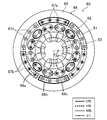
- FIG. 6 is a cross-sectional view showing a configuration example of the second bearingless motor, and shows a magnet magnetic flux, a driving magnetic flux, and a supporting magnetic flux.
- the turbo compressor (1) of this embodiment is provided in a refrigerant circuit (not shown) that performs a refrigeration cycle, and compresses the refrigerant.
- the turbo compressor (1) includes a casing (10), an impeller (20), a drive shaft (30), a touchdown bearing (40, 41), and a thrust magnetic bearing (50).
- the first bearingless motor (60) and the second bearingless motor (70) are arranged side by side in the axial direction of the drive shaft (30).
- the drive shaft (30) and the first and second bearingless motors (60, 70) constitute an electric motor system (2).
- the impeller (20) constitutes a load, but the type of load is not limited to the impeller (20).
- the “axial direction” means the rotational axis direction and the direction of the axis of the drive shaft (30), and the “radial direction” means the drive shaft ( 30) in the direction perpendicular to the axial direction.
- the “outer peripheral side” is a side farther from the axis of the drive shaft (30), and the “inner peripheral side” is a side closer to the axis of the drive shaft (30).
- the casing (10) is formed in a cylindrical shape whose both ends are closed, and is arranged so that the cylinder axis is in a horizontal direction.
- the space in the casing (10) is partitioned by the wall (11), and the space on the right side of the wall (11) constitutes the impeller chamber (12) that houses the impeller (20), and the wall (11)
- the left-hand space constitutes an electric motor chamber (14) that houses the first and second bearingless motors (60, 70).
- a drive shaft (30) extending in the axial direction in the casing (10) connects the impeller (20) and the first and second bearingless motors (60, 70).
- the first bearingless motor (60) constitutes a bearingless motor (in this example, the bearingless motor closest to the impeller (20)) having the largest radial load acting, and the second bearingless motor (70). Constitutes a bearingless motor (in this example, a bearingless motor farthest from the impeller (20)) with the smallest maximum radial load acting.
- the impeller (20) is formed by a plurality of blades so that the outer shape is substantially conical.
- the impeller (20) is housed in the impeller chamber (12) in a state of being fixed to one end of the drive shaft (30).
- a suction pipe (15) and a discharge pipe (16) are connected to the impeller chamber (12), and a compression space (13) is formed on the outer periphery of the impeller chamber (12).
- the suction pipe (15) is provided to guide the refrigerant from the outside into the impeller chamber (12), and the discharge pipe (16) is used to return the high-pressure refrigerant compressed in the impeller chamber (12) to the outside. Is provided.
- the turbo compressor (1) is provided with two touchdown bearings (40, 41).
- One touch-down bearing (40) is provided near one end of the drive shaft (30) (right end in FIG. 1), and the other touch-down bearing (41) is located near the other end of the drive shaft (30). Is provided.
- These touch-down bearings (40, 41) are used when the first and second bearingless motors (60, 70) are de-energized (that is, when the drive shaft (30) is not lifted). 30) is configured to support.
- the thrust magnetic bearing (50) has first and second electromagnets (51, 52), and the other end of the drive shaft (30) (that is, the impeller (20) is fixed).
- the disc-shaped portion (hereinafter referred to as disc portion (31)) provided on the opposite end to the one end portion is configured to be supported in a non-contact manner by electromagnetic force.
- the thrust magnetic bearing (50) controls the current flowing through the first and second electromagnets (51, 52) to thereby oppose the first and second electromagnets (51, 52) in opposite directions (that is, axial direction,
- the position of the supported portion (disk portion (31)) of the drive shaft (30) in the left-right direction in FIG. 1 can be controlled.
- the control unit (90) is a gap sensor (not shown) that can detect a gap between the disc part (31) and the thrust magnetic bearing (50) so that the position of the drive shaft (30) becomes a desired position. 1) and a gap sensor (not shown) capable of detecting the gap between the stator (64,74) and the rotor (61,71) in the first and second bearingless motors (60,70). ) And the voltage command value (thrust voltage command value) for controlling the voltage supplied to the thrust magnetic bearing (50) based on the target rotation speed information of the impeller (20) and the drive shaft (30). Alternatively, a voltage command value (motor voltage command value) for controlling the voltage supplied to the first and second bearingless motors (60, 70) is output.
- the control unit (90) can be configured by a microcomputer (not shown) and a program for operating the microcomputer.
- the first power supply unit (91) supplies a voltage to the first bearingless motor (60) based on the motor voltage command value from the control unit (90).
- the second power supply unit (92) supplies a voltage to the second bearingless motor (70) based on the motor voltage command value from the control unit (90).
- a 3rd power supply part (93) supplies a voltage to a thrust magnetic bearing (50) based on a control part (90) thrust voltage command value.
- the first power supply unit (91) generates a magnetic flux that contributes to the radial load of the drive shaft (30) (that is, the drive magnetic flux and the support magnetic flux). The maximum value is large.
- the first to third power supply units (91 to 93) can be configured by PWM (Pulse Width Modulation) amplifiers, respectively.
- the first power supply unit (91) constitutes an electric circuit corresponding to the first bearingless motor (60)
- the second power supply unit (92) constitutes an electric circuit corresponding to the second bearingless motor (70). Yes.
- the first bearingless motor (60) is disposed on the side close to the impeller (20) in the motor chamber (14).
- the first bearingless motor (60) is configured to rotationally drive the drive shaft (30) by electromagnetic force and to support the radial load of the drive shaft (30) in a non-contact manner.
- the first bearingless motor (60) has a pair of rotors (61) and a stator (64).
- the rotor (61) is fixed to the drive shaft (30), and the stator (64) is fixed to the inner peripheral wall of the casing (10).
- FIG. 2 is a cross-sectional view showing a configuration example of the first bearingless motor (60).
- the first bearingless motor (60) is a concurrent pole type bearingless motor.
- the stator (64) of the first bearingless motor (60) includes a back yoke portion (65), a plurality of teeth portions (not shown), driving coils (66a to 66c) wound around the teeth portions, And supporting coils (67a to 67c).
- the rotor (61) of the first bearingless motor (60) includes a core part (62) and a plurality (four in this example) of permanent magnets (63) embedded in the core part (62). Have.
- the stator (64) is made of a magnetic material (for example, a laminated steel plate).
- the back yoke portion (65) of the stator (64) is formed in a cylindrical shape.
- the drive coils (66a to 66c) and the support coils (67a to 67c) are wound around each tooth portion by a distributed winding method.
- the drive coils (66a to 66c) and the support coils (67a to 67c) may be wound around each tooth portion by a concentrated winding method.
- the drive coils (66a to 66c) are coils wound on the inner peripheral side of the tooth portion.
- the driving coils (66a to 66c) are surrounded by a thin solid line and a U phase driving coil (66a) surrounded by a thick solid line, a V phase driving coil (66b) surrounded by a thick broken line in FIG. W-phase driving coil (66c) shown.
- the number of turns of the drive coils (66a to 66c) of the first bearingless motor (60) is larger than the number of turns of the drive coils (76a to 76c) of the second bearingless motor (70) described later.
- a part of the driving magnetic flux generated by the driving coils (66a to 66c, 76a to 76c) contributes to the generation of the supporting force that supports the radial load of the driving shaft (30) (that is, the driving magnetic flux
- the first bearingless motor (60) is likely to generate a larger radial support force than the second bearingless motor (70).
- the number of turns of the drive coils (66a to 66c) of the first bearingless motor (60) may be equal to or less than the number of turns of the drive coils (76a to 76c) of the second bearingless motor (70).
- the support coils (67a to 67c) are coils wound around the outer periphery of the tooth portion.
- the supporting coils (67a to 67c) are surrounded by a thin solid line and a U-phase supporting coil (67a) surrounded by a thick solid line, a V-phase supporting coil (67b) surrounded by a thick broken line in FIG. W-phase supporting coil (67c) shown.
- the number of turns of the support coils (67a to 67c) of the first bearingless motor (60) is larger than the number of turns of the support coils (77a to 77c) of the second bearingless motor (70) described later.
- the first bearingless motor (60) has a supporting magnetic flux (that is, the driving shaft (30) of the driving shaft (30) for supporting the radial load of the driving shaft (30) as compared with the second bearingless motor (70)).
- the magnetic flux that contributes to supporting the radial load can be generated more greatly.
- the product of the number of turns of the drive coils (66a to 66c) and the number of turns of the support coils (67a to 67c) in the first bearingless motor (60) is the drive coil ( It is larger than the product of the number of turns of 76a to 76c) and the number of turns of the supporting coil (77a to 77c).
- the first bearingless motor (60) has a larger maximum support force for supporting the radial load of the drive shaft (30) than the second bearingless motor (70). If the magnitude relationship of the products is satisfied, the number of turns of the support coils (67a to 67c) of the first bearingless motor (60) is set to the support coil of the second bearingless motor (70) ( 77a to 77c) or less.
- the core (62) of the rotor (61) is formed in a cylindrical shape.
- a shaft hole (not shown) for inserting the drive shaft (30) is formed in the central portion of the core portion (62).
- the core part (62) is comprised with the magnetic material (for example, laminated steel plate).
- four permanent magnets (63) having a shape along the outer peripheral surface are embedded at an angular pitch (AP1) of 90 ° in the circumferential direction of the rotor (61). ing. These four permanent magnets (63) have the same shape.
- the outer peripheral surface side of each permanent magnet (63) is an N pole, and the outer peripheral surface of the core part (62) between the permanent magnets (63) is a pseudo S pole.
- the outer peripheral surface side of each permanent magnet (63) may be a south pole.
- FIG. 3 shows a magnetic flux ⁇ 1 generated by each permanent magnet (63) in the first bearingless motor (60), and a driving magnetic flux BM1 generated for rotationally driving the impeller (20) and the drive shaft (30). It is shown.
- the first bearingless motor (60) rotates the driving torque T1 (that is, the driving shaft (30) shown in FIG. 3 in the counterclockwise direction of FIG. 3 by the interaction between the magnet magnetic flux ⁇ 1 and the driving magnetic flux BM1. Torque) to be generated.
- a current IM1 equivalent to the current flowing through the driving coils (66a to 66c) is shown.
- FIG. 4 in the first bearingless motor (60), a magnet magnetic flux ⁇ 1 generated by each permanent magnet (63), and a supporting magnetic flux BS1 generated to support the radial load of the drive shaft (30) in a non-contact manner. It is shown.
- the first bearingless motor (60) has the supporting force F1 shown in the figure (that is, the force pushing the drive shaft (30) in the right direction in FIG. 4) by the interaction between the magnet magnetic flux ⁇ 1 and the supporting magnetic flux BS1. Is configured to generate.
- a current IS1 equivalent to the current flowing through the supporting coils (67a to 67c) is shown.
- the magnetic path of the supporting magnetic flux BS1 that contributes to supporting the radial load of the drive shaft (30) includes the back yoke portion (65) and the teeth portion of the stator (64), the air gap, This is a path passing through the core (62) of the rotor (61).
- the magnetic resistance of the back yoke portion (65), the teeth portion, and the core portion (62) is smaller than the magnetic resistance of the permanent magnet (63). Therefore, the first bearingless motor (60) includes the second bearingless motor (70) (that is, the drive shaft) in which the permanent magnet (73) is disposed on substantially the entire outer peripheral surface of the rotor (71) as described later.
- the first bearingless motor (60) can generate a larger radial support force for supporting the radial load of the drive shaft (30) than the second bearingless motor (70). That is, the first bearingless motor (60) has a larger maximum support force for supporting the radial load of the drive shaft (30) than the second bearingless motor (70).
- FIG. 5 shows a magnetic flux ⁇ 1 generated by each permanent magnet (63) in the first bearingless motor (60), and a driving magnetic flux BM1 generated for rotationally driving the impeller (20) and the drive shaft (30).
- the support magnetic flux BS1 generated to support the radial load of the drive shaft (30) in a non-contact manner is shown.
- the first bearingless motor (60) is configured to simultaneously generate the driving torque T1 and the supporting force F1 shown in the figure by the interaction of the magnet magnetic flux ⁇ 1, the driving magnetic flux BM1, and the supporting magnetic flux BS1. Yes.
- currents IM2 and IS2 equivalent to currents flowing through the drive coils (66a to 66c) and the support coils (67a to 67c) are shown.
- the second bearingless motor (70) is disposed on the far side from the impeller (20) in the motor chamber (14).
- the second bearingless motor (70) is configured to rotationally drive the drive shaft (30) by electromagnetic force and to support the radial load of the drive shaft (30) in a non-contact manner.
- the second bearingless motor (70) has a pair of rotors (71) and a stator (74).
- the rotor (71) is fixed to the drive shaft (30), and the stator (74) is fixed to the inner peripheral wall of the casing (10).
- FIG. 6 is a cross-sectional view showing a configuration example of the second bearingless motor (70).
- the second bearingless motor (70) is an embedded magnet type bearingless motor that exhibits substantially the same behavior as a surface magnet type bearingless motor.
- the configuration of the stator (74) of the second bearingless motor (70) is the same as that of the stator (64) of the first bearingless motor (60) except for the number of turns of each coil (76a to 76c, 77a to 77c). Same as the configuration. Specifically, the number of turns of the drive coils (76a to 76c) of the second bearingless motor (70) is larger than the number of turns of the drive coils (66a to 66c) of the first bearingless motor (60). As a result, the second bearingless motor (70) generates a larger driving magnetic flux for rotationally driving the impeller (20) and the drive shaft (30) than the first bearingless motor (60). Can do. Further, the number of turns of the support coils (77a to 77c) of the second bearingless motor (70) is smaller than the number of turns of the support coils (67a to 67c) of the first bearingless motor (60).
- the rotor (71) of the second bearingless motor (70) includes a core part (72) and a plurality (eight in this example) of permanent magnets (73) embedded in the core part (72). Have.
- the core part (72) of the rotor (71) is formed in a cylindrical shape.
- a shaft hole (not shown) for inserting the drive shaft (30) is formed at the center of the core part (72).
- the core part (72) is comprised with the magnetic material (for example, laminated steel plate).
- eight permanent magnets (73) having a shape along the outer peripheral surface have an angular pitch (AP2) (ie, AP2) of 45 ° in the circumferential direction of the rotor (71).
- the first bearingless motor (60) is embedded at an angle pitch of 90 ° (half of AP1).
- These eight permanent magnets (73) have the same shape, and the four permanent magnets (63) of the first bearingless motor (60) have the same shape.
- N poles and S poles appear alternately in the circumferential direction of the rotor (71).
- the second bearingless motor (70) causes the drive torque T2 (that is, the drive shaft (30) shown in FIG. 6 to be reversed from that shown in FIG. 6 by the interaction of the magnet magnetic flux ⁇ 2, the drive magnetic flux BM2, and the support magnetic flux BS2.
- a torque that rotates clockwise) and a supporting force F2 that is, a force that pushes the drive shaft (30) in the right direction in FIG. 6) are generated at the same time.
- the magnetic path of the supporting magnetic flux BS2 includes the back yoke portion (75) and the tooth portion of the stator (74), the air gap, the permanent magnet (73) and the core of the rotor (71). This is a route passing through the section (72).
- the number of permanent magnets (73) in the second bearingless motor (70) is larger than the number of permanent magnets (63) in the first bearingless motor (60).
- the second bearingless motor (70) has a higher magnetic flux density of the magnet magnetic flux generated by the permanent magnet (73) than the first bearingless motor (60) (see FIG. 3). Therefore, the second bearingless motor (70) can generate a larger driving torque for rotationally driving the impeller (20) and the drive shaft (30) than the first bearingless motor (60). .
- a plurality of (in this example, 100) core sheets are formed by punching a steel plate material with a predetermined mold (not shown).
- the mold used in the first step is a mold capable of forming at least through holes corresponding to four permanent magnets (63) arranged at an angular pitch (AP1) of 90 °.
- AP1 angular pitch
- die used at a 1st step is a metal mold
- the rotor (61) of the first bearingless motor (60) is laminated by stacking a part of the core sheets (50 sheets in this example) formed in the first step.
- a core part (62) is formed.
- the permanent magnet (63) is inserted into the through hole of the core portion (62) formed in the second step.
- the rotor (61) of the first bearingless motor (60) can be manufactured.
- the fourth step four more through holes are provided in the remaining portions (in this example, 50 sheets) of the plurality of core sheets formed in the first step, between the four through holes formed in the first step.
- it is formed by punching.
- the same mold as that in the first step may be rotated by 45 ° in the circumferential direction and reused, or a mold different from that in the first step may be used.
- a plurality (50 in this example) of core sheets in which eight through holes are arranged at an angular pitch (AP2) of 45 ° are formed.
- the core portion (72) of the rotor (71) of the second bearingless motor (70) is formed by laminating the plurality of core sheets formed in the fourth step.
- the permanent magnet (73) is inserted into the through hole of the core portion (72) formed in the fifth step.
- the core sheet of the rotor (61) of the first bearingless motor (60) and the core sheet of the rotor (71) of the second bearingless motor (70) are formed. Therefore, a common mold can be used at least in the first step. Thereby, the manufacturing cost of the first and second bearingless motors (60, 70) can be reduced, and consequently the manufacturing cost of the turbo compressor (1) can be reduced.
- the execution order of the second to sixth steps may be appropriately changed as long as the rotor (61, 71) can be manufactured.
- the fourth step may be executed before the second step.
- the radial load of the drive shaft (30) is supported in a non-contact manner only by the two bearingless motors (60, 70). Therefore, the two radial magnetic bearings used in the conventional turbo compressor can be omitted, and the rotating system including the impeller (20) and the drive shaft (30) can be reduced in size.
- the rotational frequency of the rotating system including the impeller (20) and the drive shaft (30) increases as the axial length decreases. Therefore, in the present embodiment, the rotating system including the impeller (20) and the drive shaft (30) is downsized compared to the conventional one, the axial length thereof is shortened, and the resonance frequency is increased. As a result, the operating range in which the turbo compressor (1) can be operated safely can be expanded.
- the first bearingless motor (60) is designed to be suitable for supporting a large radial load
- the second bearingless motor (70) is suitable for generating a large driving torque.
- the first bearingless motor (60) capable of supporting a large radial load is disposed on the side close to the impeller (20) where a relatively large radial load is generated in the drive shaft (30).
- a second bearingless motor (70) is provided on the side far from the impeller (20) where a relatively small radial load is generated, which is not suitable for supporting a large radial load, but can generate a large driving torque. ing.
- the first and second bearingless motors (60, 70) are connected to the load of the turbo compressor (1) of the type in which the impeller (20) is attached to one end of the drive shaft (30). Design and arrangement suitable for the characteristics can be made. Therefore, the rotating system including the impeller (20) and the drive shaft (30) can be further reduced in size.
- the first bearingless motor (60) in order to configure the first bearingless motor (60) so as to be suitable for supporting a large radial load of the drive shaft (30) (that is, an electromagnetic force that supports the radial load is generated).
- an electromagnetic force that supports the radial load is generated.
- the magnetic resistance of the magnetic path through which the supporting magnetic flux for supporting the radial load of the drive shaft (30) in the first bearingless motor (60) flows is larger than that in the second bearingless motor (70). It is small.
- the first power supply unit (91) corresponding to the first bearingless motor (60) is compared with the second power supply unit (92) corresponding to the second bearingless motor (70), and the driving magnetic flux and The maximum value of the current for generating the supporting magnetic flux is configured to be large.
- the number of turns of the drive coils (66a to 66c) and the support coils (67a to 67c) of the first bearingless motor (60) is determined by the number of turns of the drive coils (67a to 66c) of the second bearingless motor (70). 67c) and the number of turns of the supporting coils (77a to 77c).
- all the permanent magnets (63) of the first bearingless motor (60) and all the permanent magnets (73) of the second bearingless motor (70) have the same shape. As a result, there is no need to produce permanent magnets having different shapes, so that the cost of the first and second bearingless motors (60, 70) can be reduced, and the cost of the turbo compressor (1) can be reduced. .
- the number of the permanent magnets (73) which the 2nd bearingless motor (70) has (specifically, 8) is twice the number (specifically, four) of the permanent magnets (63) of the first bearingless motor (60).
- the angular pitch (AP2) (specifically, 45 °) between the permanent magnets (73) adjacent in the circumferential direction of the rotor (71) in the second bearingless motor (70) is the first bearingless motor. It is half of that in (60) (specifically, 90 °).
- the first bearingless motor (60) has an electric motor type (specifically, a concurrent pole type) and a second bearingless motor (70) has an electric motor type (specifically, an embedded magnet type).
- the motor types of both bearingless motors (60, 70) may be the same.
- the first bearingless motor (60) has a higher magnetic permeability of the magnetic material used for the stator (64,74) and the rotor (61,71) than the second bearingless motor (70). do it.
- the first bearingless motor (60), compared with the second bearingless motor (70), has a magnetic resistance (that is, a magnetic path for generating a supporting force for supporting the radial load of the drive shaft (30) (that is, the magnetic resistance).
- the driving magnetic flux that contributes to supporting the radial load of the drive shaft (30) and the magnetic resistance of the magnetic path through which the supporting magnetic flux flows are small, and thus the maximum value of the supporting force that supports the radial load is large.
- the turbo compressor (1) includes two bearingless motors (60, 70), but may include three or more bearingless motors.
- the first bearingless motor (60) is a concurrent pole type bearingless motor, but the type of the first bearingless motor (60) is not limited thereto.
- the type of the second bearingless motor (70) is not limited to that of the above embodiment.
- each bearingless motor (60, 70) is provided with a drive coil (66a to 66c, 76a to 76c) and a support coil (67a to 67c, 77a to 77c).
- a common coil having the functions (66a to 66c, 67a to 67c, 76a to 76c, 77a to 77c) may be provided.
- a difference from the magnetic flux ⁇ 2 generated by the magnet (73) is generated.
- the magnetic flux ⁇ 1 generated by the permanent magnet (63) of the one bearingless motor (60) may be different from the magnetic flux ⁇ 2 generated by the permanent magnet (73) of the second bearingless motor (70).
- all the permanent magnets (63) of the first bearingless motor (60) and all the permanent magnets (73) of the second bearingless motor (70) have the same shape.
- the shapes of the permanent magnets (63, 73) may be different from each other.
- the rotor (61, 71) and the stator (64, 74) are made of laminated steel plates, but the rotor (61, 71) and stator (64) are made of a material other than the laminated steel plates. , 74).
- the turbo compressor (1) includes only one impeller (20), but may include two or more impellers (20).
- one impeller (20) may be attached to each end of the drive shaft (30).
- turbo compressor (1) including the electric motor system (2) has been described.
- the use of the electric motor system (2) is not limited to the turbo compressor (1).
- the present invention is useful for an electric motor system and a turbo compressor including the same.
Landscapes
- Engineering & Computer Science (AREA)
- General Engineering & Computer Science (AREA)
- Mechanical Engineering (AREA)
- Power Engineering (AREA)
- Physics & Mathematics (AREA)
- Electromagnetism (AREA)
- Magnetic Bearings And Hydrostatic Bearings (AREA)
- Structures Of Non-Positive Displacement Pumps (AREA)
- Connection Of Motors, Electrical Generators, Mechanical Devices, And The Like (AREA)
Priority Applications (3)
| Application Number | Priority Date | Filing Date | Title |
|---|---|---|---|
| EP18798805.0A EP3598616A4 (de) | 2017-05-09 | 2018-04-27 | Elektromotorsystem und damit ausgestatteter turboverdichter |
| US16/606,440 US11300131B2 (en) | 2017-05-09 | 2018-04-27 | Electric motor system and turbo compressor provided therewith |
| CN201880024326.4A CN110537318B (zh) | 2017-05-09 | 2018-04-27 | 电动机系统及包括该电动机系统的涡轮压缩机 |
Applications Claiming Priority (2)
| Application Number | Priority Date | Filing Date | Title |
|---|---|---|---|
| JP2017-093330 | 2017-05-09 | ||
| JP2017093330A JP6447662B2 (ja) | 2017-05-09 | 2017-05-09 | 電動機システムおよびそれを備えたターボ圧縮機 |
Publications (1)
| Publication Number | Publication Date |
|---|---|
| WO2018207669A1 true WO2018207669A1 (ja) | 2018-11-15 |
Family
ID=64104555
Family Applications (1)
| Application Number | Title | Priority Date | Filing Date |
|---|---|---|---|
| PCT/JP2018/017198 WO2018207669A1 (ja) | 2017-05-09 | 2018-04-27 | 電動機システムおよびそれを備えたターボ圧縮機 |
Country Status (5)
| Country | Link |
|---|---|
| US (1) | US11300131B2 (de) |
| EP (1) | EP3598616A4 (de) |
| JP (1) | JP6447662B2 (de) |
| CN (1) | CN110537318B (de) |
| WO (1) | WO2018207669A1 (de) |
Cited By (1)
| Publication number | Priority date | Publication date | Assignee | Title |
|---|---|---|---|---|
| CN109454189A (zh) * | 2019-01-16 | 2019-03-12 | 成都航空职业技术学院 | 一种电磁式径向成形设备 |
Families Citing this family (7)
| Publication number | Priority date | Publication date | Assignee | Title |
|---|---|---|---|---|
| CN114876825A (zh) * | 2017-03-24 | 2022-08-09 | 江森自控泰科知识产权控股有限责任合伙公司 | 磁性轴承马达压缩机 |
| JP6447662B2 (ja) * | 2017-05-09 | 2019-01-09 | ダイキン工業株式会社 | 電動機システムおよびそれを備えたターボ圧縮機 |
| JP7299477B2 (ja) | 2019-03-27 | 2023-06-28 | ダイキン工業株式会社 | 電動機システム |
| CN111049345B (zh) * | 2020-01-06 | 2022-03-11 | 浙江大学 | 轴向磁通游标电机 |
| JP6978703B2 (ja) * | 2020-03-31 | 2021-12-08 | ダイキン工業株式会社 | 遠心型圧縮機 |
| US11831220B2 (en) | 2020-06-22 | 2023-11-28 | Textron Innovations Inc. | Electric motor stack with integral one-piece gearbox input shaft |
| US11814163B2 (en) | 2021-01-13 | 2023-11-14 | Textron Innovations Inc. | Electric tiltrotor aircraft with tilting coaxial motors and gearbox |
Citations (14)
| Publication number | Priority date | Publication date | Assignee | Title |
|---|---|---|---|---|
| JP2524492Y2 (ja) * | 1990-08-08 | 1997-01-29 | 光洋精工株式会社 | 変速機用軸受装置 |
| JP2000076676A (ja) * | 1998-09-02 | 2000-03-14 | Seiko Seiki Co Ltd | ディスク記録及び/又は再生装置 |
| JP2002253576A (ja) * | 2001-03-02 | 2002-09-10 | Akira Chiba | 歯科用ハンドピース |
| JP2002364535A (ja) * | 2001-06-08 | 2002-12-18 | Toyota Industries Corp | 回転装置 |
| JP2004120886A (ja) * | 2002-09-26 | 2004-04-15 | Rikogaku Shinkokai | ベアリングレスモータ |
| JP2008125203A (ja) * | 2006-11-10 | 2008-05-29 | Meidensha Corp | ベアリングレスモータに適用した順突極モータ |
| JP2010180974A (ja) * | 2009-02-06 | 2010-08-19 | Meidensha Corp | ベアリングレスモータのパラメータ設定方法 |
| JP2010252605A (ja) * | 2009-04-20 | 2010-11-04 | Asmo Co Ltd | モータ |
| JP2013505697A (ja) * | 2009-09-18 | 2013-02-14 | コリア エレクトロテクノロジー リサーチ インスティチュート | 直接駆動式の電気機器 |
| WO2013080998A1 (ja) * | 2011-11-29 | 2013-06-06 | Thk株式会社 | 垂直軸型風車用軸受及び垂直軸型風力発電装置 |
| JP2014005833A (ja) * | 2012-06-22 | 2014-01-16 | Eskaef Manutic Mechatronic | 車輌用遠心式電動コンプレッサ |
| JP2014241725A (ja) | 2010-03-15 | 2014-12-25 | 学校法人東京理科大学 | ベアリングレスモータ |
| JP2016114114A (ja) | 2014-12-12 | 2016-06-23 | ダイキン工業株式会社 | スラスト磁気軸受 |
| JP2016171625A (ja) * | 2015-03-11 | 2016-09-23 | パナソニック株式会社 | モータ、該モータを備えるモータ装置及び該モータ装置を備える洗濯機 |
Family Cites Families (26)
| Publication number | Priority date | Publication date | Assignee | Title |
|---|---|---|---|---|
| JPS5969522A (ja) * | 1982-09-21 | 1984-04-19 | Seiko Instr & Electronics Ltd | 磁気軸受装置 |
| JPS60256983A (ja) * | 1984-06-01 | 1985-12-18 | Koyo Seiko Co Ltd | デイスク状記録担体の読みとり装置用スピンドルユニツト |
| GB2268984B (en) * | 1992-07-23 | 1996-04-03 | Glacier Metal Co Ltd | Magnetic bearing back-up |
| US5708346A (en) * | 1994-01-10 | 1998-01-13 | Sulzer Electronics Ag | Method and control apparatus for controlling an AC-machine |
| JP3550584B2 (ja) * | 1995-04-21 | 2004-08-04 | 正 深尾 | 電磁回転機械 |
| US6324134B1 (en) | 1998-08-05 | 2001-11-27 | Seiko Instruments Inc. | Disk recording and reproducing apparatus |
| JP3877912B2 (ja) * | 1999-05-25 | 2007-02-07 | 株式会社荏原製作所 | 放電励起エキシマレーザ装置 |
| JP2002122138A (ja) * | 2000-10-16 | 2002-04-26 | Seiko Instruments Inc | 磁気軸受装置 |
| FR2817088B1 (fr) * | 2000-11-17 | 2003-02-21 | Mecanique Magnetique Sa | Machine tournante a butee axiale magnetique integrant une generatrice de courant |
| JP4071510B2 (ja) * | 2001-04-25 | 2008-04-02 | 松下電器産業株式会社 | 電動機 |
| JP4293185B2 (ja) * | 2003-07-04 | 2009-07-08 | 三菱電機株式会社 | 磁気軸受装置 |
| US7456537B1 (en) * | 2004-12-17 | 2008-11-25 | The University Of Toledo | Control system for bearingless motor-generator |
| FR2896285B1 (fr) * | 2006-01-13 | 2008-04-18 | Mecanique Magnetique Sa Soc D | Dispositif de suspension magnetique d'un rotor |
| EP2107668A1 (de) * | 2007-01-22 | 2009-10-07 | Tokyo University Of Science Educational Foundation Administrative Organization | Elektrische rotationsmaschine |
| JP2008221433A (ja) * | 2007-03-15 | 2008-09-25 | Jtekt Corp | 研削装置 |
| WO2009093428A1 (ja) * | 2008-01-24 | 2009-07-30 | Tokyo University Of Science Educational Foundation Administrative Organization | ベアリングレスモータ |
| US8084911B2 (en) * | 2008-10-16 | 2011-12-27 | Asmo Co., Ltd. | Motor |
| US8115358B1 (en) * | 2009-03-18 | 2012-02-14 | Mikhail A Rakov | Method and systems for operating magnetic bearings and bearingless drives |
| JP6155573B2 (ja) * | 2012-08-28 | 2017-07-05 | 株式会社Ihi | 遠心圧縮機 |
| US9657744B2 (en) * | 2013-02-13 | 2017-05-23 | Dresser-Rand Company | Midspan active magnetic bearing |
| EP3168487B1 (de) * | 2014-09-01 | 2018-11-14 | Daikin Industries, Ltd. | Magnetlager |
| JP6389785B2 (ja) * | 2015-03-18 | 2018-09-12 | 株式会社日立製作所 | ダウンホール圧縮機 |
| DE102016004714A1 (de) * | 2016-04-19 | 2017-10-19 | Saurer Germany Gmbh & Co. Kg | Spinnrotorschaft, Lageranordnung zum aktiven magnetischen Lagern eines solchen Spinnrotorschafts und Spinnrotorantriebseinrichtung |
| FI129747B (en) * | 2017-03-22 | 2022-08-15 | Lappeenrannan Teknillinen Yliopisto | Control device and method for controlling an electrical operation |
| JP6447662B2 (ja) * | 2017-05-09 | 2019-01-09 | ダイキン工業株式会社 | 電動機システムおよびそれを備えたターボ圧縮機 |
| CN108539914B (zh) * | 2018-04-27 | 2023-09-08 | 南京工程学院 | 一种三相四自由度轴向分相磁悬浮飞轮电机 |
-
2017
- 2017-05-09 JP JP2017093330A patent/JP6447662B2/ja active Active
-
2018
- 2018-04-27 WO PCT/JP2018/017198 patent/WO2018207669A1/ja unknown
- 2018-04-27 CN CN201880024326.4A patent/CN110537318B/zh active Active
- 2018-04-27 US US16/606,440 patent/US11300131B2/en active Active
- 2018-04-27 EP EP18798805.0A patent/EP3598616A4/de active Pending
Patent Citations (14)
| Publication number | Priority date | Publication date | Assignee | Title |
|---|---|---|---|---|
| JP2524492Y2 (ja) * | 1990-08-08 | 1997-01-29 | 光洋精工株式会社 | 変速機用軸受装置 |
| JP2000076676A (ja) * | 1998-09-02 | 2000-03-14 | Seiko Seiki Co Ltd | ディスク記録及び/又は再生装置 |
| JP2002253576A (ja) * | 2001-03-02 | 2002-09-10 | Akira Chiba | 歯科用ハンドピース |
| JP2002364535A (ja) * | 2001-06-08 | 2002-12-18 | Toyota Industries Corp | 回転装置 |
| JP2004120886A (ja) * | 2002-09-26 | 2004-04-15 | Rikogaku Shinkokai | ベアリングレスモータ |
| JP2008125203A (ja) * | 2006-11-10 | 2008-05-29 | Meidensha Corp | ベアリングレスモータに適用した順突極モータ |
| JP2010180974A (ja) * | 2009-02-06 | 2010-08-19 | Meidensha Corp | ベアリングレスモータのパラメータ設定方法 |
| JP2010252605A (ja) * | 2009-04-20 | 2010-11-04 | Asmo Co Ltd | モータ |
| JP2013505697A (ja) * | 2009-09-18 | 2013-02-14 | コリア エレクトロテクノロジー リサーチ インスティチュート | 直接駆動式の電気機器 |
| JP2014241725A (ja) | 2010-03-15 | 2014-12-25 | 学校法人東京理科大学 | ベアリングレスモータ |
| WO2013080998A1 (ja) * | 2011-11-29 | 2013-06-06 | Thk株式会社 | 垂直軸型風車用軸受及び垂直軸型風力発電装置 |
| JP2014005833A (ja) * | 2012-06-22 | 2014-01-16 | Eskaef Manutic Mechatronic | 車輌用遠心式電動コンプレッサ |
| JP2016114114A (ja) | 2014-12-12 | 2016-06-23 | ダイキン工業株式会社 | スラスト磁気軸受 |
| JP2016171625A (ja) * | 2015-03-11 | 2016-09-23 | パナソニック株式会社 | モータ、該モータを備えるモータ装置及び該モータ装置を備える洗濯機 |
Non-Patent Citations (1)
| Title |
|---|
| See also references of EP3598616A4 |
Cited By (1)
| Publication number | Priority date | Publication date | Assignee | Title |
|---|---|---|---|---|
| CN109454189A (zh) * | 2019-01-16 | 2019-03-12 | 成都航空职业技术学院 | 一种电磁式径向成形设备 |
Also Published As
| Publication number | Publication date |
|---|---|
| EP3598616A1 (de) | 2020-01-22 |
| JP6447662B2 (ja) | 2019-01-09 |
| US20210108646A1 (en) | 2021-04-15 |
| CN110537318B (zh) | 2021-08-13 |
| US11300131B2 (en) | 2022-04-12 |
| EP3598616A4 (de) | 2020-12-30 |
| JP2018191455A (ja) | 2018-11-29 |
| CN110537318A (zh) | 2019-12-03 |
Similar Documents
| Publication | Publication Date | Title |
|---|---|---|
| JP6447662B2 (ja) | 電動機システムおよびそれを備えたターボ圧縮機 | |
| JP6422595B2 (ja) | 電動機および空気調和機 | |
| US7411330B2 (en) | Rotating electric machine | |
| JP2002507878A (ja) | 電気モータ又は発電機 | |
| JP4791013B2 (ja) | ブラシレスモータ | |
| JP2013046571A (ja) | ブラシレスモータ | |
| WO2020230507A1 (ja) | ロータ及びそれを備えたモータ | |
| JP7299477B2 (ja) | 電動機システム | |
| JP2009005572A (ja) | 磁気誘導子形同期回転機およびそれを用いた自動車用過給機 | |
| JP2011024291A (ja) | ステータコア及びアキシャルギャップモータ | |
| CN103199642A (zh) | 电机 | |
| JP2013050180A (ja) | 磁気軸受機構 | |
| JP2021129443A (ja) | モータ | |
| JP6368917B2 (ja) | 電動機およびこの電動機を備えた電気機器 | |
| US20190372411A1 (en) | Rotor and motor using same | |
| JP2008136348A (ja) | 電気モータ又は発電機 | |
| JP2008253127A (ja) | 電気モータ又は発電機 | |
| JP2006254622A (ja) | 永久磁石型電動機 | |
| JP2005529575A (ja) | 相互作用するステータ要素及びロータ要素間のエアギャップが変化する回転永久磁石型電動モータ | |
| JP5855903B2 (ja) | ロータ及びモータ | |
| JP7475301B2 (ja) | 電動機システム、ターボ圧縮機、及び冷凍装置 | |
| JP2011024385A (ja) | 二重回転子構造磁気支持モータ及び該二重回転子構造磁気支持モータを搭載したターンテーブル | |
| JP2007116850A (ja) | 永久磁石式回転電機および円筒型リニアモータ | |
| JP2020162345A (ja) | 電動機システム | |
| JP5251531B2 (ja) | 可変特性回転電機 |
Legal Events
| Date | Code | Title | Description |
|---|---|---|---|
| 121 | Ep: the epo has been informed by wipo that ep was designated in this application |
Ref document number: 18798805 Country of ref document: EP Kind code of ref document: A1 |
|
| ENP | Entry into the national phase |
Ref document number: 2018798805 Country of ref document: EP Effective date: 20191015 |
|
| NENP | Non-entry into the national phase |
Ref country code: DE |