WO2018207650A1 - デッキプレート及びコンクリート構造体 - Google Patents
デッキプレート及びコンクリート構造体 Download PDFInfo
- Publication number
- WO2018207650A1 WO2018207650A1 PCT/JP2018/017102 JP2018017102W WO2018207650A1 WO 2018207650 A1 WO2018207650 A1 WO 2018207650A1 JP 2018017102 W JP2018017102 W JP 2018017102W WO 2018207650 A1 WO2018207650 A1 WO 2018207650A1
- Authority
- WO
- WIPO (PCT)
- Prior art keywords
- deck plate
- plate according
- concavo
- uneven
- protrusion
- Prior art date
- Legal status (The legal status is an assumption and is not a legal conclusion. Google has not performed a legal analysis and makes no representation as to the accuracy of the status listed.)
- Ceased
Links
Images


Classifications
-
- E—FIXED CONSTRUCTIONS
- E04—BUILDING
- E04B—GENERAL BUILDING CONSTRUCTIONS; WALLS, e.g. PARTITIONS; ROOFS; FLOORS; CEILINGS; INSULATION OR OTHER PROTECTION OF BUILDINGS
- E04B5/00—Floors; Floor construction with regard to insulation; Connections specially adapted therefor
- E04B5/16—Load-carrying floor structures wholly or partly cast or similarly formed in situ
- E04B5/32—Floor structures wholly cast in situ with or without form units or reinforcements
- E04B5/36—Floor structures wholly cast in situ with or without form units or reinforcements with form units as part of the floor
- E04B5/38—Floor structures wholly cast in situ with or without form units or reinforcements with form units as part of the floor with slab-shaped form units acting simultaneously as reinforcement; Form slabs with reinforcements extending laterally outside the element
- E04B5/40—Floor structures wholly cast in situ with or without form units or reinforcements with form units as part of the floor with slab-shaped form units acting simultaneously as reinforcement; Form slabs with reinforcements extending laterally outside the element with metal form-slabs
Definitions
- the present invention relates to a deck plate and a concrete structure used for building a floor structure or a ceiling structure of a building.
- Deck plates are widely used as formwork when building floor structures and ceiling structures of buildings.
- the deck plate is installed so as to be bridged between the beams, and both end portions of the deck plate are fixed to the upper surface of the beam. After the deck plate is fixed, concrete is placed on the deck plate, and the concrete is solidified to construct a floor structure or a ceiling structure.
- the deck plate is formed by roll forming a single thin plate material (metal plate).
- the deck plate is formed with ribs for increasing rigidity (see, for example, Patent Document 1). Since the upper surface of the deck plate is flat, there is no resistance to the boundary surface (contact surface) with the lower surface of the floor structure or the ceiling structure. Therefore, the deck plate is used as a mold material having rigidity capable of withstanding a load until solidification of the concrete. Deck plates are often impossible to remove after solidification and are often left behind.
- a deck plate which can form a plurality of concave and convex grooves on the upper surface of the deck plate so that the adjacent positions are shifted from each other, improve adhesion to the placed concrete and prevent cracking of the concrete.
- a deck plate is disclosed in which a plurality of embosses are formed on the flat portion of the deck plate so that adjacent positions are displaced from each other (see, for example, Patent Documents 3 and 4).
- JP 7-238621 A Japanese Utility Model Publication No. 1-122111 JP 7-269003 A Japanese Patent Laid-Open No. 8-100466
- the deck plate has a resistance to the boundary with the concrete. Since it does not have, it has almost no function which resists a horizontal load even if it is left, and the frictional force at the interface between the deck plate and the concrete is not large.
- the deck plate is produced by a roll forming machine, the oil on the roller is attached to the surface, or rainwater is attached to the surface because it is used outdoors. The coefficient of friction often decreases. Therefore, the frictional force at the boundary between the deck plate and the concrete may not be sufficient.
- concave and convex grooves are formed in the flat portion of the deck plate.
- an object of the present invention is to provide a deck plate that can compensate for the reduced friction coefficient, increase the quality and rigidity, and suppress the decrease in work efficiency.
- the present invention is a deck plate formed of a metal plate, and on one surface, ribs extending from one end to the other end along the suspension direction at intervals from each other; It is characterized in that both end portions of the rib are provided with end close portions crushed in a direction perpendicular to the one surface, and uneven portions formed in flat portions between the adjacent ribs.
- the uneven portion extends in a direction intersecting with the extending direction of the rib.
- a plurality of the uneven portions are formed at intervals along the extending direction of the ribs.
- the uneven portions formed in a region sandwiched between the adjacent ribs and the uneven portions formed in a region adjacent to the region are arranged in a staggered manner.
- the uneven portion formed in one region is shifted in the extending direction of the rib by a distance that is half the interval between the adjacent uneven portions formed in the other region. Preferably it is.
- the friction coefficient ⁇ of one uneven portion is ⁇ ⁇ 0.05.
- the slip resistance coefficient C. S. R is 0.4 ⁇ C. S. It is preferable that R ⁇ 0.9.
- the present invention is a concrete structure, characterized in that it includes the above-described deck plate and a concrete layer that is cast on the top surface of the deck plate and formed integrally with the deck plate by solidification.
- the reduced friction coefficient can be compensated, quality and rigidity can be improved, and reduction in work efficiency can be suppressed.
- FIG. 1 It is a figure which shows the deck plate installed between the beams. It is a perspective view of a deck plate. It is a top view of a deck plate. It is a front view of a deck plate. It is a partial cross section figure of a floor structure (or ceiling structure). It is a figure explaining the theory at the time of calculating
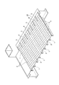
- FIG. 1 is a view showing a deck plate installed between beams.
- FIG. 2 is a perspective view of the deck plate.
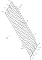
- FIG. 3 is a plan view of the deck plate.
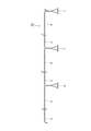
- FIG. 4 is a front view of the deck plate.
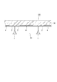
- FIG. 5 is a partial cross-sectional view of the floor structure (or ceiling structure).
- the deck plate 10 becomes a concrete formwork placed when a floor structure or a ceiling structure of a building structure is constructed.
- the deck plate 10 is one that increases the rigidity of the floor structure (or ceiling structure) 100 together with the concrete after the concrete is solidified. That is, as shown in FIG. 5, in the present embodiment, the floor structure (or ceiling structure) 100 is placed on the deck plate 10 and the upper surface of the deck plate 10, and is integrated with the deck plate 10 by solidification. And a concrete layer 30 formed on the surface.
- the deck plate 10 is bridged between the beams 20 facing each other.
- the deck plate 10 has one end placed on one beam 20 and fixed to the beam 20 by welding or the like, and the other end placed on the other beam 20 and fixed to the beam 20 by welding or the like.
- the beam 20 is made of, for example, H-shaped steel, and each end portion of the deck plate 10 is placed on and fixed to a flange portion of the H-shaped steel constituting each beam 20.
- the deck plate 10 is formed of a thin plate steel plate (metal plate) that has been subjected to a plating process such as galvanization.
- the deck plate 10 is manufactured by roll-forming a single flat steel plate with a roll forming machine.
- the deck plate 10 is bent at a plurality of locations by a roll forming machine.
- the deck plate 10 includes a rib 1, a flat portion 2, an end close portion 3, and a ridge portion 4 (uneven portion).
- the rib 1 is formed by bending a steel plate.
- the rib 1 is configured to be bent to one surface side of the steel plate at a predetermined interval, bent a plurality of times in the middle, and then bent along the surface direction of the steel plate at the first bending position.
- the ribs 1 are connected by a caulking process or the like between steel plates that are partially folded. This prevents the rib 1 from opening.
- a plurality of ribs 1 are formed at predetermined intervals along the width direction (short direction) of the deck plate 10.
- the rib 1 is formed so as to extend along the length direction (longitudinal direction) of the deck plate 10. That is, the rib 1 is formed continuously from one end to the other end along the suspension direction to the beam 20.
- the flat portion 2 is a portion that is not bent in the deck plate 10. That is, the flat portion 2 is a portion sandwiched between adjacent ribs 1. In the deck plate 10, each flat part 2 is formed on the same plane.
- the end close portions 3 are formed at both ends in the length direction (longitudinal direction) of the deck plate 10.
- the end close portion 3 is formed by crushing both end portions of the rib 1 in a direction perpendicular to the surface of the deck plate 10.
- the rib 1 is formed in the cross section by which the end close part 3 of the both ends was crushed, and the other part pinched
- both end portions of the rib 1 have a lower height than other portions, and can be placed on the upper surface of the flange portion of the beam 20.
- the end close portion 3 is formed such that the length along the extending direction of the rib 1 is longer than the length placed on the upper surface of the flange portion of the beam 20.
- the protruding portion 4 is formed on each flat portion 2.
- the protruding portion 4 is formed by, for example, embossing, and is formed so as to protrude on the side opposite to the rib 1 in the deck plate 10.
- the protruding portion 4 extends along a direction orthogonal to the extending direction of the rib 1, that is, along the width direction (short direction) of the deck plate 10.
- the protrusion 4 can increase resistance to a horizontal load by engaging concrete with the concrete after placing and solidifying the top surface of the deck plate 10.
- the length L of the protrusions 4 when the protrusions 4 are formed in a staggered pattern is the length Ls of the protrusions when the protrusions 4 are not formed in a staggered pattern. It is preferable that it is 2 times.
- a plurality of the protrusions 4 are formed at predetermined intervals along the extending direction of the rib 1, that is, the length direction (longitudinal direction) of the deck plate 10.
- the length and width of the protrusion 4 and the amount of protrusion from the surface of the flat portion 2 are determined by the following theory.
- the width B of the protrusion 4 and the protrusion amount t from the surface of the flat portion 2 will be considered.
- a horizontal load acts on one object (concrete) and gets over the other object (deck plate).
- the drop of (0.6 to 0.75) may be compensated by the protrusion 4 having the friction coefficient ⁇ calculated by the equation (3).
- the ratio between the width B of the protrusion 4 and the protrusion amount t may be adjusted. Specifically, if the protrusion amount t is increased and the width B is decreased, the friction coefficient ⁇ can be increased.
- the friction coefficient ⁇ of the protrusion 4 is ⁇ 0.067.
- the friction coefficient ⁇ of the protrusion 4 is ⁇ 0.233.
- the friction coefficient ⁇ is preferably in the range of 0.05 ⁇ ⁇ ⁇ 1.65.
- the friction coefficient ⁇ was set to 0.05 ⁇ ⁇ ⁇ 1.65 because the friction coefficient ⁇ was set within this range, so that “the test by the Tokyo Institute of Technology slide tester OY-PSM (JIS A 1454). In “Polymer-lined flooring test method”), the slip resistance coefficient C.I. S. This is because R falls within the range of 0.4 to 0.9, and the surface of the deck plate 10 is not slippery for the operator and is excellent in safety.
- Table 1 shows that the above sliding test was conducted after water and dust were sprayed on the surface of the four types of deck plates, and the sliding resistance coefficient C.I. S. The result of measuring R is shown.
- the test body 1 is a flat plate material on which no protrusion is formed, and the plate thickness is 1.2 mm.
- the length of the protruding portion is 120 mm, the width is 15 mm, the protruding amount is 1.5 mm, the interval between the protruding portions adjacent in the longitudinal direction is 80 mm, and the plate thickness is 0.8 mm.
- the length of the protruding portion is 120 mm, the width is 15 mm, the protruding amount is 3 mm, the interval between the protruding portions adjacent in the longitudinal direction is 50 mm, and the plate thickness is 1.6 mm.
- the length of the protrusions is 120 mm, the width is 15 mm, the protrusion amount is 3 mm, the interval between the protrusions adjacent in the longitudinal direction is 50 mm, and the plate thickness is 1.2 mm.
- the slip test is performed along the longitudinal direction and the short direction of the deck plate for each of the specimens 1 to 4, and the slip resistance coefficient C.I. S. R was measured.
- the slip resistance coefficient C.I. S. R is also 0.4 to 0.42, and the slip resistance coefficient C.I. S. R can be within the range of 0.4 to 0.9.
- the slip resistance coefficient C.I. S. R is also 0.4 to 0.44, and the slip resistance coefficient C.I. S. R can be within the range of 0.4 to 0.9.
- the length L of the ridge 4 will be considered.
- the length of the protrusion 4 can be considered by viewing one protrusion 4 in the deck plate 10 from the longitudinal side (Y direction). Since the element that resists the horizontal load is considered to be the cross-sectional projected area of the protrusion 4, it is necessary to approximate the cross-sectional projected areas in the X direction and the Y direction.
- the length L in the longitudinal direction of one ridge 4 is the projected area of the cross section when the ridge 4 is viewed from the short side A, and the ridge aligned along the short direction of the ridge 4.
- the number (number of rows) of the portions 4 is m
- the number (number of columns) of the protrusions 4 arranged along the longitudinal direction of the protrusions 4 is n
- the protrusion amount is t
- L mA / nt (4)
- the cross-sectional projected area A of the protrusion 4 is A ⁇ 10 mm 2 .
- the length L of one protrusion 4 is L ⁇ 86.7 mm.
- the length L, the width B, and the protrusion amount t of the protrusion 4 can be designed according to the friction coefficient ⁇ required for the deck plate 10.
- the ridges 4 formed on each flat part 2 are the ridges 4 formed on one flat part 2 and the ridges formed on the flat part 2 adjacent to the one flat part 2. 4 are arranged in a staggered pattern when the deck plate 10 is viewed in plan view. More specifically, among the adjacent flat portions 2, the protrusion 4 formed on one flat portion 2 is half the interval G between the adjacent protrusions 4 formed on the other flat portion 2. Is shifted in the extending direction of the rib 1 by the distance of.
- the deck plate 10 has the protruding portion 4 formed on the flat portion 2, so that oil from the roller of the roll forming machine or rainwater or the like adheres to the surface of the deck plate 10. Even if the friction coefficient of the surface that should originally be reduced is reduced, the friction coefficient of the deck plate 10 can be increased by the friction coefficient of the ridges 4 with the reduced friction coefficient. Thereby, the frictional force between the concrete and the deck plate 10 can be increased and integrated as a floor structure or a ceiling structure, and the function of resisting a horizontal load acting due to an earthquake or the like can be enhanced. .
- the protrusion 4 having the above-described configuration in the flat portion 3, it is possible to effectively increase the frictional force between the concrete and the deck plate 10 while minimizing the increase in the number of steps and weight. it can.
- Resistance coefficient C.I. S. R can be set within a range of 0.4 to 0.9, and the slip resistance of the deck plate 10 can be greatly improved by the slip resistance as well as the anti-slip property during the work.
- the improved friction coefficient compensates for the decrease in the friction coefficient due to oil or rainwater, and the frictional force between the concrete and the deck plate 10 can be increased, and the floor structure or the ceiling structure can be more integrated. It is possible to enhance the function of resisting a horizontal load acting due to an earthquake or the like.
- the ridges 4 it is possible to suppress the generation of wrinkles due to the stress difference between the periphery of the rib 1 having a large bend and the flat part 2 that is not bent, and the quality of the manufactured deck plate 10 can be reduced. Can be increased. Moreover, since the generation
- the ridge portion 4 protruding from the flat portion 2 functions as a non-slip member that prevents a worker walking on the deck plate 10 from slipping. Can be suppressed.
- the slip resistance coefficient C.D. S. By setting R within the range of 0.4 to 0.9 where the slip evaluation scale is safe, when the deck plate 10 is considered as a work floor, the deck plate 10 having excellent slip resistance can be obtained. .
- the protrusion part 4 which protrudes from the flat part 2 reflects light irregularly by forming the protrusion part 4, the anti-glare effect to an operator can be improved. Furthermore, since the reflection of sunlight in summer can be suppressed, the burden on the operator can be reduced, and the reduction in work efficiency can be suppressed.
- the ridges 4 can be formed over the entire surface of the flat portion 2, and the above-described effects can be further enhanced.
- the protrusions 4 can be formed over the entire surface of the flat portion 2, and the above-described effects can be further enhanced.
- the protrusions 4 have the same cross-sectional projected area of the protrusions 4 in the X direction and the Y direction of the deck plate 10.
- the part 4 is designed, the overlapping of the protrusions 4 when viewed from the X direction can be reduced by arranging the protrusions 4 in a staggered manner. Therefore, the cross-sectional projection area can be increased with a small number, and the number of protrusions 4 to be formed on the deck plate 10 can be reduced, so that the amount of metal plate necessary for the production of the deck plate 10 can be reduced. Can be reduced in weight.
- the deck plate 10 is formed of a metal plate, it is not necessary to support from below, and the lower space can be used effectively. Further, since the deck plate 10 has the end close portions 3 at both ends, the deck plate 10 can be placed on the upper surface of the beam 20. In addition, it is not necessary to provide a member for preventing leakage of concrete between the deck plate 10 and the form of the beam 20. In the case of RC construction, a part of the end close portion 3 can be bitten into the beam 20, so that the effect of preventing the deck plate 10 from falling off can be enhanced. Further, when concrete is placed on the deck plate 10, the ridges 4 solidify in a state where they have digged into the concrete, so that the ridges 4 function as engaging portions with the concrete.
- the rigidity of the ceiling structure can be increased. Further, since the protrusions 4 extend in the longitudinal direction of the deck plate 10 and are formed along the short direction of the deck plate 10, in the length direction and the width direction of the deck plate 10. Concrete can be engaged with the protrusions 4 to increase the rigidity of the floor structure or the ceiling structure.
- the protrusions 4 as the concavo-convex portions are not limited to the case where the protrusions 4 protrude on the surface opposite to the rib 1 but may be formed so as to protrude in the same direction as the rib 1.
- a groove is formed in the flat portion 2 when viewed from the surface opposite to the rib 1.
- grooved part should just be uneven
- the deck plate after solidifying the placed concrete, the deck plate is left and the deck plate is used as a reinforcing material for the floor structure or the ceiling structure, but it is not necessarily left.
- the deck plate may be removed after the concrete is solidified. That is, the deck plate may be used only as a formwork.
Landscapes
- Engineering & Computer Science (AREA)
- Architecture (AREA)
- Physics & Mathematics (AREA)
- Electromagnetism (AREA)
- Civil Engineering (AREA)
- Structural Engineering (AREA)
- Floor Finish (AREA)
- Panels For Use In Building Construction (AREA)
- Buildings Adapted To Withstand Abnormal External Influences (AREA)
- Forms Removed On Construction Sites Or Auxiliary Members Thereof (AREA)
Abstract
低下した摩擦係数を補い、品質や剛性を高め、作業効率の低下を抑えること。 金属板から形成されるデッキプレート(10)であって、一方の面において、互いに間隔をあけて懸架方向に沿って一端から他端にわたって延在するリブ(1)と、リブ(1)の両端部が一方の面に対して直角方向に潰されたエンドクローズ部(3)と、隣接するリブ(1)間の平坦部(2)に形成された凹凸部(4)と、を備える。
Description
本発明は、建物の床構造体や天井構造体の構築に用いるデッキプレート及びコンクリート構造体に関する。
建物の床構造体や天井構造体を構築する際の型枠として、デッキプレートが広く用いられている。デッキプレートは、梁間に架け渡されるように設置されており、デッキプレートの両端部が梁の上面に固定されている。デッキプレートを固定した後、デッキプレートの上にはコンクリートが打設され、コンクリートが固化することにより、床構造体または天井構造体が構築される。
デッキプレートは、一枚の薄板材(金属板)をロール成形することにより形成されている。デッキプレートには、剛性を高めるためのリブが形成されている(例えば、特許文献1参照)。デッキプレートの上面は平坦であるため、床構造体または天井構造体の下面との境界面(当接面)には抵抗力がない。よって、デッキプレートは、型枠材としてコンクリート固化までの荷重に耐えうる剛性を有するものとして用いられている。デッキプレートはコンクリート固化後、取り外すことが不可能なことが多く、残置されることも多い。
一方、デッキプレートの上面に、隣接する位置が相互にずれるように多数の凹凸溝を形成し、打設したコンクリートとの密着性を良くしてコンクリートのひび割れを防止することができるデッキプレートが開示されている(例えば、特許文献2参照)。
また、デッキプレートの平坦部に、隣接する位置が互いにずれるように複数のエンボスを形成したデッキプレートが開示されている(例えば、特許文献3,4参照)。
また、デッキプレートの平坦部に、隣接する位置が互いにずれるように複数のエンボスを形成したデッキプレートが開示されている(例えば、特許文献3,4参照)。
ところで、床構造体または天井構造体には、地震荷重のような水平荷重が作用するため、その荷重に耐えうる構造を求められることがあるが、デッキプレートは、コンクリートとの境界に抵抗力を有しないため、残置されていても水平荷重に対して抵抗する機能はほとんどなく、デッキプレートとコンクリートとの境界面の摩擦力は大きなものではない。さらに、デッキプレートは、ロール成形機によって生産されることから、表面にローラの油分が付着していたり、屋外で用いられることから雨水等が付着することによって、本来有しているはずの表面の摩擦係数が低下していることが多い。そのため、デッキプレートとコンクリートとの境界の摩擦力が十分ではないことがある。特許文献2においては、デッキプレートの平坦部に凹凸溝が形成されており、特許文献3,4においては、デッキプレートの平坦部にエンボスが形成されているが、いずれも摩擦係数の低下を補う手法については検討されていない。
また、デッキプレートにおいては、大きな曲げ加工が施されたリブと加工されていない平坦部との応力差により、平坦部に皺が発生し、品質の高いデッキプレートの成形を困難なものとしている。
また、リブ間の平坦部においては、リブ周辺に比べて剛性が不足しているため、打設されたコンクリートの重量や施工時の作業者の歩行によって変形してしまうおそれがある。
また、デッキプレートは金属板から形成されているため、平坦な領域が多いと滑りやすく、さらには光の反射によって作業を阻害し、作業効率が低下するおそれがある。
また、デッキプレートにおいては、大きな曲げ加工が施されたリブと加工されていない平坦部との応力差により、平坦部に皺が発生し、品質の高いデッキプレートの成形を困難なものとしている。
また、リブ間の平坦部においては、リブ周辺に比べて剛性が不足しているため、打設されたコンクリートの重量や施工時の作業者の歩行によって変形してしまうおそれがある。
また、デッキプレートは金属板から形成されているため、平坦な領域が多いと滑りやすく、さらには光の反射によって作業を阻害し、作業効率が低下するおそれがある。
そこで、本発明は、上記課題に鑑みてなされたものであり、低下した摩擦係数を補い、品質や剛性を高め、作業効率の低下を抑えることができるデッキプレートを提供することを目的とする。
上記の課題を解決するため、本発明は、金属板から形成されるデッキプレートであって、一方の面において、互いに間隔をあけて懸架方向に沿って一端から他端にわたって延在するリブと、前記リブの両端部が前記一方の面に対して直角方向に潰されたエンドクローズ部と、隣接する前記リブ間の平坦部に形成された凹凸部と、を備えることを特徴とする。
また、前記凹凸部は、前記リブの延在方向に交差する方向に延在していることが好ましい。
また、前記凹凸部は、前記リブの延在方向に沿って間隔をあけて複数形成されていることが好ましい。
また、隣接する前記リブに挟まれた領域に形成されている前記凹凸部と、この領域に隣接する領域に形成されている前記凹凸部とが千鳥状に配置されていることが好ましい。
また、前記凹凸部の長さLは、L=43mm~260mmであることが好ましい。
また、隣接する領域のうち、一方の領域に形成されている前記凹凸部は、他方の領域に形成された隣接する前記凹凸部の間隔の半分の距離だけ前記リブの延在方向にずらされていることが好ましい。
また、隣接する前記凹凸部の間隔Gは、G=50mm~100mmであることが好ましい。
また、一つの前記凹凸部の摩擦係数μは、μ≧0.05であることが好ましい。
また、前記平坦部表面の滑り抵抗係数C.S.Rは、0.4≦C.S.R≦0.9であることが好ましい。
また、一つの前記凹凸部の長さLは、前記凹凸部を短手側から見た断面積をA、前記凹凸部の短手方向に沿って並んだ前記凹凸部の個数をm、前記凹凸部の長手方向に沿って並んだ前記凹凸部の個数をn、前記凹凸部の前記平坦部表面からの凹凸量をtとしたときに、L=mA/ntであることが好ましい。
また、前記凹凸部の幅Bは、B=10mm~30mmであることが好ましい。
また、前記凹凸部の前記平坦部表面からの凹凸量tは、t=1.0mm~3.5mmであることが好ましい。
本発明は、コンクリート構造体であって、上記のデッキプレートと、前記デッキプレートの上面に打設され、固化により前記デッキプレートと一体に形成されたコンクリート層と、を備えることを特徴とする。
本発明によれば、低下した摩擦係数を補い、品質や剛性を高め、作業効率の低下を抑えることができる。
本発明の好ましい実施の形態について、図面を参照しながら説明する。なお、以下に示す実施の形態は一例であり、本発明の範囲において、種々の実施の形態をとりうる。
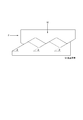
図1は、梁間に設置されたデッキプレートを示す図である。図2は、デッキプレートの斜視図である。図3は、デッキプレートの平面図である。図4は、デッキプレートの正面図である。図5は、床構造体(または天井構造体)の一部断面図である。
図1から図4に示すように、デッキプレート10は、建築構造物の床構造体または天井構造体を構築する際に打設されるコンクリートの型枠となる。また、図5に示すように、デッキプレート10は、コンクリートの固化後、コンクリートと一体となって床構造体(または天井構造体)100の剛性を高めるものである。すなわち、図5に示すように、本実施の形態において、床構造体(または天井構造体)100は、デッキプレート10と、このデッキプレート10の上面に打設され、固化によりデッキプレート10と一体に形成されたコンクリート層30と、を備えている。
図1から図4に示すように、デッキプレート10は、建築構造物の床構造体または天井構造体を構築する際に打設されるコンクリートの型枠となる。また、図5に示すように、デッキプレート10は、コンクリートの固化後、コンクリートと一体となって床構造体(または天井構造体)100の剛性を高めるものである。すなわち、図5に示すように、本実施の形態において、床構造体(または天井構造体)100は、デッキプレート10と、このデッキプレート10の上面に打設され、固化によりデッキプレート10と一体に形成されたコンクリート層30と、を備えている。
<デッキプレートの構成>
図1に示すように、デッキプレート10は、対向する梁20間に架け渡されている。デッキプレート10は、一端が一方の梁20に載置され、溶接等によって梁20に固定されており、他端が他方の梁20に載置され、溶接等によって梁20に固定されている。具体的に、梁20は、例えば、H形鋼によって構成されており、デッキプレート10の各端部はそれぞれの梁20を構成するH形鋼のフランジ部に載置され、固定されている。
図1に示すように、デッキプレート10は、対向する梁20間に架け渡されている。デッキプレート10は、一端が一方の梁20に載置され、溶接等によって梁20に固定されており、他端が他方の梁20に載置され、溶接等によって梁20に固定されている。具体的に、梁20は、例えば、H形鋼によって構成されており、デッキプレート10の各端部はそれぞれの梁20を構成するH形鋼のフランジ部に載置され、固定されている。
図2から図4に示すように、デッキプレート10は、亜鉛メッキ等のメッキ処理が施された薄板状の鋼板(金属板)から形成されている。デッキプレート10は、一枚の平板状の鋼板をロール成形機によってロール成形することにより製造される。デッキプレート10は、ロール成形機によって複数の箇所で曲げ加工が施される。
デッキプレート10は、リブ1と、平坦部2と、エンドクローズ部3と、突条部4(凹凸部)と、を備えている。
デッキプレート10は、リブ1と、平坦部2と、エンドクローズ部3と、突条部4(凹凸部)と、を備えている。
リブ1は、鋼板が曲げ加工されることによって形成されている。リブ1は、所定間隔をあけて鋼板の一方の面側に曲げられ、途中で複数回曲げられた後、最初の曲げ位置で鋼板の面方向に沿うように曲げられて構成されている。リブ1は、一部において折り返された鋼板同士がカシメ加工等によって連結されている。これによって、リブ1が開かないようになっている。リブ1は、デッキプレート10の幅方向(短手方向)に沿って所定の間隔をあけて複数形成されている。リブ1は、デッキプレート10の長さ方向(長手方向)に沿って延在するように形成されている。すなわち、リブ1は、梁20への懸架方向に沿って一端から他端にわたって連続して形成されている。
平坦部2は、デッキプレート10において曲げ加工が施されていない部分である。すなわち、平坦部2は、隣接するリブ1に挟まれた部分である。デッキプレート10において、各平坦部2は、同一平面上に形成されている。
エンドクローズ部3は、デッキプレート10の長さ方向(長手方向)の両端部に形成されている。エンドクローズ部3は、リブ1の両端部がデッキプレート10の面に対して直角方向に潰されることによって形成されている。これにより、リブ1は、両端部のエンドクローズ部3が押し潰された断面に形成されており、エンドクローズ部3に挟まれた他の部分は断面視略三角形状に形成されている。その結果、リブ1の両端部は、他の部分よりも高さが低くなるため、梁20のフランジ部上面に載置することができる。エンドクローズ部3は、リブ1の延在方向に沿った長さが梁20のフランジ部上面に載置する長さよりも長くなるように形成されている。
突条部4は、各平坦部2に形成されている。突条部4は、例えば、エンボス加工によって形成されており、デッキプレート10においてリブ1とは反対側に突出するように形成されている。突条部4は、リブ1の延在方向に直交する方向、すなわち、デッキプレート10の幅方向(短手方向)に沿って延在している。突条部4は、デッキプレート10の上面にコンクリートを打設して固化した後、コンクリートに係合していることで水平荷重に対する抵抗力を高めることができる。突条部4について、例えば、長さLは、L=43mm~260mm、幅Bは、B=10mm~30mm、平坦部2の表面からの突出量tは、t=1.0mm~3.5mmであることが好ましい。また、デッキプレート10において、各突条部4を千鳥状に形成した場合における突条部4の長さLは、突条部4を千鳥状に形成しない場合における突条部の長さLsの2倍であることが好ましい。
突条部4は、リブ1の延在方向、すなわち、デッキプレート10の長さ方向(長手方向)に沿って所定間隔をあけて複数形成されている。ここで、隣接する突条部4の間隔Gは、例えば、G=50mm~100mmであることが好ましい。
突条部4は、リブ1の延在方向、すなわち、デッキプレート10の長さ方向(長手方向)に沿って所定間隔をあけて複数形成されている。ここで、隣接する突条部4の間隔Gは、例えば、G=50mm~100mmであることが好ましい。
ここで、突条部4の長さ、幅、平坦部2表面からの突出量は、以下の理論によって定められる。
最初に、突条部4の幅Bと平坦部2表面からの突出量tについて考える。
図6に示すように、凹凸を有する二つの物体(コンクリートとデッキプレート)が係合している場合において、一方の物体(コンクリート)に水平荷重が作用して他方の物体(デッキプレート)を乗り越えようとするときの摩擦係数μを考える。この場合、クーロンーアモントンの法則により、一方の物体(コンクリート)の垂直荷重をW、一方の物体(コンクリート)が他方の物体(デッキプレート)を乗り越える力をF、凸部(突条部)の傾斜角をθとすると、摩擦係数μは、以下の式(1)で求めることができる。
μ=tanθ ・・・ (1)
最初に、突条部4の幅Bと平坦部2表面からの突出量tについて考える。
図6に示すように、凹凸を有する二つの物体(コンクリートとデッキプレート)が係合している場合において、一方の物体(コンクリート)に水平荷重が作用して他方の物体(デッキプレート)を乗り越えようとするときの摩擦係数μを考える。この場合、クーロンーアモントンの法則により、一方の物体(コンクリート)の垂直荷重をW、一方の物体(コンクリート)が他方の物体(デッキプレート)を乗り越える力をF、凸部(突条部)の傾斜角をθとすると、摩擦係数μは、以下の式(1)で求めることができる。
μ=tanθ ・・・ (1)
次に、図7に示すように、デッキプレート10における一つの突条部4を短手側(X方向)から見た場合について考える。ここでは、近似値として、突条部4の各端部C,Dから短手側の中心(幅の中心)の位置Eまでを直線で結び、この直線の平坦部2に対する傾斜角をθとして突条部4の摩擦係数μを考える。この場合、突条部4の幅(短手側の長さ)をB、突条部4の平坦部2の表面からの突出量(深さ)をtとしたときに、以下の式(2)の関係が成立する。
1/2×B=t/tanθ ・・・ (2)
ここで、式(1)を式(2)に代入すると、摩擦係数μは、以下の式(3)で求めることができる。
μ=2t/B ・・・ (3)
1/2×B=t/tanθ ・・・ (2)
ここで、式(1)を式(2)に代入すると、摩擦係数μは、以下の式(3)で求めることができる。
μ=2t/B ・・・ (3)
すなわち、デッキプレート10の表面にロール成形機のローラの油分が付着したり、施工時に雨水等が付着することによって、本来、コンクリートとデッキプレート10との接触面が有しているはずの摩擦係数(0.6~0.75)の低下分を式(3)で算出される摩擦係数μを有する突条部4で補えばよい。また、摩擦係数μの大きさを調節するには、突条部4の幅Bと突出量tとの比を調整すればよい。具体的には、突出量tを大きくし、幅Bを小さくすれば、摩擦係数μを大きくすることができる。
例えば、突出量t=1.0mm、幅B=10mmで突条部4を形成した場合には、突条部4の摩擦係数μは、μ=0.2となる。また、突出量t=1.0mm、幅B=30mmで突条部4を形成した場合には、突条部4の摩擦係数μは、μ≒0.067となる。また、突出量t=3.5mm、幅B=10mmで突条部4を形成した場合には、突条部4の摩擦係数μは、μ=0.7となる。また、突出量t=3.5mm、幅B=30mmで突条部4を形成した場合には、突条部4の摩擦係数μは、μ≒0.233となる。
なお、摩擦係数μは、0.05≦μ≦1.65の範囲内にあることが好ましい。
例えば、突出量t=1.0mm、幅B=10mmで突条部4を形成した場合には、突条部4の摩擦係数μは、μ=0.2となる。また、突出量t=1.0mm、幅B=30mmで突条部4を形成した場合には、突条部4の摩擦係数μは、μ≒0.067となる。また、突出量t=3.5mm、幅B=10mmで突条部4を形成した場合には、突条部4の摩擦係数μは、μ=0.7となる。また、突出量t=3.5mm、幅B=30mmで突条部4を形成した場合には、突条部4の摩擦係数μは、μ≒0.233となる。
なお、摩擦係数μは、0.05≦μ≦1.65の範囲内にあることが好ましい。
ここで、摩擦係数μを0.05≦μ≦1.65としたのは、摩擦係数μをこの範囲にすることで、「東京工業大学式の滑り試験機OY-PSMによる試験(JIS A 1454「高分子張り床材試験方法」に規定)」において、滑り抵抗係数C.S.Rが0.4~0.9の範囲内に収まり、デッキプレート10の表面が作業者にとって滑りにくく、安全性に優れたものとなるからである。
表1は、4種類のデッキプレートの表面に水と埃を散布した後に、上記の滑り試験を行い、滑り抵抗係数C.S.Rを測定した結果を示すものである。試験体1は、突条部が形成されていない平坦な板材であり、板厚は1.2mmである。試験体2は、突条部の長さが120mm、幅が15mm、突出量が1.5mm、長手方向に隣接する突条部の間隔が80mmであり、板厚は0.8mmである。試験体3は、突条部の長さが120mm、幅が15mm、突出量が3mm、長手方向に隣接する突条部の間隔が50mmであり、板厚は1.6mmである。試験体4は、突条部の長さが120mm、幅が15mm、突出量が3mm、長手方向に隣接する突条部の間隔が50mmであり、板厚は1.2mmである。滑り試験は、試験体1~4毎にデッキプレートの長手方向及び短手方向に沿って行い、それぞれの場合の滑り抵抗係数C.S.Rを測定した。

ここで、例えば、コンクリートとデッキプレートの接触面の摩擦係数μを0.6とし、雨水や油分の付着により、摩擦係数μが0.2低下してしまう場合、表1の試験体2のデッキプレート10のように、突出量t=1.5mm、幅B=15mmの突条部4を形成することにより、摩擦係数μを0.2高めることができるので、コンクリートとデッキプレート10の接触面の摩擦係数μはμ=0.6(元々の接触面の摩擦係数)-0.2(雨水等による摩擦係数の低下分)+0.2(突条部の形成による摩擦係数の増加分)=0.6となり、雨水等による摩擦係数の低下分を突条部4の形成で補うことができる。また、滑り抵抗係数C.S.Rも0.4~0.42となり、滑り抵抗係数C.S.Rを0.4~0.9の範囲内に収めることができる。
また、コンクリートとデッキプレートの接触面の摩擦係数μを0.6とし、雨水や油分の付着により、摩擦係数μが0.4低下してしまう場合、表1の試験体3,4のデッキプレート10のように、突出量t=3mm、幅B=15mmの突条部4を形成することにより、摩擦係数μを0.4高めることができるので、コンクリートとデッキプレート10の接触面の摩擦係数μはμ=0.6(元々の接触面の摩擦係数)-0.4(雨水等による摩擦係数の低下分)+0.4(突条部の形成による摩擦係数の増加分)=0.6となり、雨水等による摩擦係数の低下分を突条部4の形成で補うことができる。また、滑り抵抗係数C.S.Rも0.4~0.44となり、滑り抵抗係数C.S.Rを0.4~0.9の範囲内に収めることができる。
次に、突条部4の長さLについて考える。突条部4の長さは、デッキプレート10における一つの突条部4を長手側(Y方向)から見ることによって考えることができる。水平荷重に抵抗する要素は、突条部4の断面投影面積と考えられるため、X方向とY方向の断面投影面積を近似させる必要がある。
この場合、一つの突条部4の長手方向の長さLは、突条部4を短手側から見た断面投影面積をA、突条部4の短手方向に沿って並んだ突条部4の個数(行の数)をm、突条部4の長手方向に沿って並んだ突条部4の個数(列の数)をn、突条部4の平坦部2の表面からの突出量をtとしたときに、以下の式(4)で求めることができる。
L=mA/nt ・・・ (4)
例えば、突出量t=1.0mm、幅B=10mmで突条部4を形成した場合には、突条部4の断面投影面積Aは、A≒10mm2となり、突条部4の短手方向に沿って並んだ突条部4の個数(行の数)m=26個、突条部4の長手方向に沿って並んだ突条部4の個数(列の数)n=3個とすると、一つの突条部4の長さLは、L≒86.7mmとなる。
以上のように考えることで、デッキプレート10に求める摩擦係数μに応じて、突条部4の長さL、幅B、突出量tを設計することができる。
この場合、一つの突条部4の長手方向の長さLは、突条部4を短手側から見た断面投影面積をA、突条部4の短手方向に沿って並んだ突条部4の個数(行の数)をm、突条部4の長手方向に沿って並んだ突条部4の個数(列の数)をn、突条部4の平坦部2の表面からの突出量をtとしたときに、以下の式(4)で求めることができる。
L=mA/nt ・・・ (4)
例えば、突出量t=1.0mm、幅B=10mmで突条部4を形成した場合には、突条部4の断面投影面積Aは、A≒10mm2となり、突条部4の短手方向に沿って並んだ突条部4の個数(行の数)m=26個、突条部4の長手方向に沿って並んだ突条部4の個数(列の数)n=3個とすると、一つの突条部4の長さLは、L≒86.7mmとなる。
以上のように考えることで、デッキプレート10に求める摩擦係数μに応じて、突条部4の長さL、幅B、突出量tを設計することができる。
各平坦部2に形成されている突条部4は、一の平坦部2に形成されている突条部4と、一の平坦部2に隣接する平坦部2に形成されている突条部4とが、デッキプレート10を平面視した際に、千鳥状に配置されている。より具体的には、隣接する平坦部2のうち、一方の平坦部2に形成されている突条部4は、他方の平坦部2に形成された隣接する突条部4の間隔Gの半分の距離だけリブ1の延在方向にずらされて形成されている。
以上のように、デッキプレート10は、平坦部2に突条部4が形成されているので、デッキプレート10の表面にロール成形機のローラの油分が付着したり、雨水等が付着することによって、本来有しているはずの表面の摩擦係数が低下している場合であっても、摩擦係数の低下分を突条部4の摩擦係数によってデッキプレート10の摩擦係数を高めることができる。これにより、コンクリートとデッキプレート10との摩擦力を高めて、床構造体または天井構造体としてより一体化させることができ、地震等によって作用する水平荷重に対して抵抗する機能を高めることができる。特に、上記のような構成の突条部4を平坦部3に形成することにより、工数や重量の増加を最小限に抑えつつ、効果的にコンクリートとデッキプレート10との摩擦力を高めることができる。
また、突条部4を上記のように構成することにより、「東京工業大学式の滑り試験機OY-PSMによる試験(JIS A 1454「高分子張り床材試験方法」に規定)」において、滑り抵抗係数C.S.Rを0.4~0.9の範囲内にすることができ、作業時の防滑性向上はもちろんのこと、その滑り抵抗がデッキプレート10の摩擦係数を大きく向上させることができる。これにより、かかる摩擦係数の向上分が油分や雨水による摩擦係数の低下分を補い、コンクリートとデッキプレート10との摩擦力を高めて、床構造体または天井構造体としてより一体化させることができ、地震等によって作用する水平荷重に対して抵抗する機能を高めることができる。
また、突条部4を形成することにより、曲げの大きなリブ1周辺と曲げ加工されていない平坦部2との応力差による皺の発生を抑えることができ、製造されるデッキプレート10の品質を高めることができる。また、突条部4を形成することにより、デッキプレート10の皺の発生を抑えることができるので、ロール成形工程を従来よりも簡単なものとすることができる。
また、突条部4を形成することにより、リブ1間の平坦部2の剛性を高めることができ、打設されたコンクリートの重量や施工時の作業者の歩行による平坦部2の変形を抑えることができる。
また、突条部4を形成することにより、リブ1間の平坦部2の剛性を高めることができ、打設されたコンクリートの重量や施工時の作業者の歩行による平坦部2の変形を抑えることができる。
また、突条部4を形成することにより、平坦部2から突出している突条部4がデッキプレート10上を歩行する作業者のスリップを防止する滑り止め部材として機能するので、作業効率の低下を抑えることができる。特に、デッキプレート10の平坦部3表面の滑り抵抗係数C.S.Rを、滑り評価尺度が安全となる0.4~0.9の範囲内にすることで、デッキプレート10を作業床として考慮した場合に、防滑性に優れたデッキプレート10とすることができる。
また、突条部4を形成することにより、平坦部2から突出している突条部4が光を乱反射させるので、作業者への防眩効果を高めることができる。さらに、夏場の日光の照り返しを抑えることができるので、作業者への負担を軽減することができ、作業効率の低下を抑えることができる。
また、突条部4を形成することにより、平坦部2から突出している突条部4が光を乱反射させるので、作業者への防眩効果を高めることができる。さらに、夏場の日光の照り返しを抑えることができるので、作業者への負担を軽減することができ、作業効率の低下を抑えることができる。
また、突条部4が千鳥状に配置されるように形成することで、平坦部2の全面にわたって突条部4を形成することができ、上記の効果をより高めることができる。特に、デッキプレート10の幅方向に隣接する突条部4を、デッキプレート10の長さ方向に隣接する突条部4の間隔の半分の距離だけずらすことで、周囲の突条部4間の距離をほぼ均等に保つことができ、上記の効果をより高めることができる。
また、上記の式(4)に示すように、あらゆる方向からの水平荷重に抵抗するため、突条部4の断面投影面積をデッキプレート10のX方向とY方向とで等しくなるように突条部4が設計されているが、突条部4を千鳥状に配置することで、X方向から見た時の突条部4同士の重なりを減らすことができる。よって、少ない数で断面投影面積を増やすことができ、デッキプレート10に形成すべき突条部4の数を減らすことができるので、デッキプレート10の生産に必要な金属板の量を減らすことができ、軽量化を図ることができる。
また、隣接する突条部4の間隔Gを、G=50mm~100mm、突条部4の長さLを、L=43mm~260mm、突条部4の幅Bを、B=10mm~30mm、突条部4の平坦部2からの突出量tを、t=1.0mm~3.5mmの範囲内で形成することで、上記の効果をより高めるのに適した突条部4とすることができる。
また、上記の式(4)に示すように、あらゆる方向からの水平荷重に抵抗するため、突条部4の断面投影面積をデッキプレート10のX方向とY方向とで等しくなるように突条部4が設計されているが、突条部4を千鳥状に配置することで、X方向から見た時の突条部4同士の重なりを減らすことができる。よって、少ない数で断面投影面積を増やすことができ、デッキプレート10に形成すべき突条部4の数を減らすことができるので、デッキプレート10の生産に必要な金属板の量を減らすことができ、軽量化を図ることができる。
また、隣接する突条部4の間隔Gを、G=50mm~100mm、突条部4の長さLを、L=43mm~260mm、突条部4の幅Bを、B=10mm~30mm、突条部4の平坦部2からの突出量tを、t=1.0mm~3.5mmの範囲内で形成することで、上記の効果をより高めるのに適した突条部4とすることができる。
また、デッキプレート10は、金属板から形成されているので、下方からの支持が不要となり、下方の空間を有効に利用できる。また、デッキプレート10は、両端部にエンドクローズ部3を有しているので、梁20の上面に載置することができる。また、デッキプレート10と梁20の型枠との間にコンクリートの漏れを防ぐ部材を設ける必要がなくなる。RC造の場合、梁20にエンドクローズ部3の一部を食い込ませることができるので、デッキプレート10の脱落防止効果を高めることができる。
また、デッキプレート10にコンクリートを打設した際、突条部4がコンクリートに食い込んだ状態で固化するので、突条部4は、コンクリートとの係合部として機能することとなり、床構造体や天井構造体の剛性を高めることができる。
また、突条部4は、デッキプレート10の長手方向に延在しているとともに、デッキプレート10の短手方向に沿って複数形成されているので、デッキプレート10の長さ方向及び幅方向においてコンクリートが突条部4に係合されて床構造体または天井構造体の剛性を高めることができる。
また、デッキプレート10にコンクリートを打設した際、突条部4がコンクリートに食い込んだ状態で固化するので、突条部4は、コンクリートとの係合部として機能することとなり、床構造体や天井構造体の剛性を高めることができる。
また、突条部4は、デッキプレート10の長手方向に延在しているとともに、デッキプレート10の短手方向に沿って複数形成されているので、デッキプレート10の長さ方向及び幅方向においてコンクリートが突条部4に係合されて床構造体または天井構造体の剛性を高めることができる。
<その他>
なお、本発明は、上記実施の形態に限られるものではない。例えば、凹凸部としての突条部4は、リブ1とは反対側の面に突出する場合に限らず、リブ1と同じ方向に突出するように形成してもよい。この場合、リブ1とは反対側の面から見れば、平坦部2に溝が形成されていることになる。また、突条部4の形成にあたっては、エンボス加工に限らず、他の加工方法を用いてもよい。また、凹凸部は、平坦部2に凹凸が形成されていればよいので、突条部4に限らず、複数の円形状の突起又は凹部を形成してもよい。この場合、ロール成形後にショットブラスト加工を施すことによって形成してもよいし、ロール成形時に型押しで形成してもよい。なお、これらの突起又は凹部と突条部4との両方を形成してもよい。さらに、平坦部2に筋状の傷を形成して、デッキプレート10の表面粗さを大きくして、光をより乱反射させて防眩効果を高めてもよい。
また、上記の実施の形態においては、打設したコンクリートの固化後に、デッキプレートを残置し、デッキプレートを床構造体又は天井構造体の補強材として用いているが、必ずしも残置する必要はなく、コンクリートの固化後にデッキプレートを取り外してもよい。すなわち、デッキプレートを単なる型枠としてのみ用いてもよい。
なお、本発明は、上記実施の形態に限られるものではない。例えば、凹凸部としての突条部4は、リブ1とは反対側の面に突出する場合に限らず、リブ1と同じ方向に突出するように形成してもよい。この場合、リブ1とは反対側の面から見れば、平坦部2に溝が形成されていることになる。また、突条部4の形成にあたっては、エンボス加工に限らず、他の加工方法を用いてもよい。また、凹凸部は、平坦部2に凹凸が形成されていればよいので、突条部4に限らず、複数の円形状の突起又は凹部を形成してもよい。この場合、ロール成形後にショットブラスト加工を施すことによって形成してもよいし、ロール成形時に型押しで形成してもよい。なお、これらの突起又は凹部と突条部4との両方を形成してもよい。さらに、平坦部2に筋状の傷を形成して、デッキプレート10の表面粗さを大きくして、光をより乱反射させて防眩効果を高めてもよい。
また、上記の実施の形態においては、打設したコンクリートの固化後に、デッキプレートを残置し、デッキプレートを床構造体又は天井構造体の補強材として用いているが、必ずしも残置する必要はなく、コンクリートの固化後にデッキプレートを取り外してもよい。すなわち、デッキプレートを単なる型枠としてのみ用いてもよい。
1 リブ
2 平坦部
3 エンドクローズ部
4 突条部(凹凸部)
10 デッキプレート
20 梁
30 コンクリート層
100 床構造体(天井構造体)
2 平坦部
3 エンドクローズ部
4 突条部(凹凸部)
10 デッキプレート
20 梁
30 コンクリート層
100 床構造体(天井構造体)
Claims (13)
- 金属板から形成されるデッキプレートであって、
一方の面において、互いに間隔をあけて懸架方向に沿って一端から他端にわたって延在するリブと、
前記リブの両端部が前記一方の面に対して直角方向に潰されたエンドクローズ部と、
隣接する前記リブ間の平坦部に形成された凹凸部と、
を備えることを特徴とするデッキプレート。 - 前記凹凸部は、前記リブの延在方向に交差する方向に延在していることを特徴とする請求項1に記載のデッキプレート。
- 前記凹凸部は、前記リブの延在方向に沿って間隔をあけて複数形成されていることを特徴とする請求項1又は2に記載のデッキプレート。
- 隣接する前記リブに挟まれた領域に形成されている前記凹凸部と、この領域に隣接する領域に形成されている前記凹凸部とが千鳥状に配置されていることを特徴とする請求項3に記載のデッキプレート。
- 前記凹凸部の長さLは、L=43mm~260mmであることを特徴とする請求項4に記載のデッキプレート。
- 隣接する領域のうち、一方の領域に形成されている前記凹凸部は、他方の領域に形成された隣接する前記凹凸部の間隔の半分の距離だけ前記リブの延在方向にずらされていることを特徴とする請求項4又は5に記載のデッキプレート。
- 隣接する前記凹凸部の間隔Gは、G=50mm~100mmであることを特徴とする請求項3~6までのいずれか一項に記載のデッキプレート。
- 一つの前記凹凸部の摩擦係数μは、
μ≧0.05
であることを特徴とする請求項1~7までのいずれか一項に記載のデッキプレート。 - 前記平坦部表面の滑り抵抗係数C.S.Rは、
0.4≦C.S.R≦0.9
であることを特徴とする請求項1~8までのいずれか一項に記載のデッキプレート。 - 一つの前記凹凸部の長さLは、前記凹凸部を短手側から見た断面積をA、前記凹凸部の短手方向に沿って並んだ前記凹凸部の個数をm、前記凹凸部の長手方向に沿って並んだ前記凹凸部の個数をn、前記凹凸部の前記平坦部表面からの凹凸量をtとしたときに、
L=mA/nt
であることを特徴とする請求項1~9までのいずれか一項に記載のデッキプレート。 - 前記凹凸部の幅Bは、B=10mm~30mmであることを特徴とする請求項1~10までのいずれか一項に記載のデッキプレート。
- 前記凹凸部の前記平坦部表面からの凹凸量tは、t=1.0mm~3.5mmであることを特徴とする請求項1~11までのいずれか一項に記載のデッキプレート。
- 請求項1~12までのいずれか一項に記載のデッキプレートと、
前記デッキプレートの上面に打設され、固化により前記デッキプレートと一体に形成されたコンクリート層と、
を備えることを特徴とするコンクリート構造体。
Priority Applications (4)
| Application Number | Priority Date | Filing Date | Title |
|---|---|---|---|
| JP2019517563A JP7051833B2 (ja) | 2017-05-12 | 2018-04-26 | デッキプレートの設計方法 |
| MYPI2019006583A MY205767A (en) | 2017-05-12 | 2018-04-26 | Deck plate and concrete structure |
| PH12019502538A PH12019502538A1 (en) | 2017-05-12 | 2019-11-12 | Deck plate and concrete structure |
| JP2022004068A JP7324882B2 (ja) | 2017-05-12 | 2022-01-14 | デッキプレート及びコンクリート構造体 |
Applications Claiming Priority (2)
| Application Number | Priority Date | Filing Date | Title |
|---|---|---|---|
| JPPCT/JP2017/017990 | 2017-05-12 | ||
| PCT/JP2017/017990 WO2018207337A1 (ja) | 2017-05-12 | 2017-05-12 | デッキプレート |
Publications (1)
| Publication Number | Publication Date |
|---|---|
| WO2018207650A1 true WO2018207650A1 (ja) | 2018-11-15 |
Family
ID=64105093
Family Applications (2)
| Application Number | Title | Priority Date | Filing Date |
|---|---|---|---|
| PCT/JP2017/017990 Ceased WO2018207337A1 (ja) | 2017-05-12 | 2017-05-12 | デッキプレート |
| PCT/JP2018/017102 Ceased WO2018207650A1 (ja) | 2017-05-12 | 2018-04-26 | デッキプレート及びコンクリート構造体 |
Family Applications Before (1)
| Application Number | Title | Priority Date | Filing Date |
|---|---|---|---|
| PCT/JP2017/017990 Ceased WO2018207337A1 (ja) | 2017-05-12 | 2017-05-12 | デッキプレート |
Country Status (4)
| Country | Link |
|---|---|
| JP (2) | JP7051833B2 (ja) |
| MY (1) | MY205767A (ja) |
| PH (1) | PH12019502538A1 (ja) |
| WO (2) | WO2018207337A1 (ja) |
Families Citing this family (2)
| Publication number | Priority date | Publication date | Assignee | Title |
|---|---|---|---|---|
| WO2018207337A1 (ja) * | 2017-05-12 | 2018-11-15 | Jfeスチール株式会社 | デッキプレート |
| JP7265890B2 (ja) * | 2019-03-04 | 2023-04-27 | Jfe建材株式会社 | デッキプレート |
Citations (7)
| Publication number | Priority date | Publication date | Assignee | Title |
|---|---|---|---|---|
| JPH01122111U (ja) * | 1988-02-15 | 1989-08-18 | ||
| JPH07238621A (ja) * | 1994-02-28 | 1995-09-12 | Nippon Kokan Raito Steel Kk | デッキプレート |
| JPH07269003A (ja) * | 1994-03-29 | 1995-10-17 | Nippon Kokan Raito Steel Kk | デッキプレート、役物デッキプレート及び調整プレート |
| JPH0849337A (ja) * | 1994-08-09 | 1996-02-20 | Sumikin Kozai Kogyo Kk | 補剛材付き床型枠鋼板 |
| JPH08100476A (ja) * | 1994-09-30 | 1996-04-16 | Nippon Kokan Light Steel Kk | デッキプレートの斜めエンドクローズ加工方法および加工プレス装置 |
| JP2007070956A (ja) * | 2005-09-09 | 2007-03-22 | Nippon Steel & Sumikin Metal Products Co Ltd | デッキプレート |
| JP2008038388A (ja) * | 2006-08-02 | 2008-02-21 | Nagashima Imono Kk | 地下構造物用鉄蓋類における滑り止め突起 |
Family Cites Families (3)
| Publication number | Priority date | Publication date | Assignee | Title |
|---|---|---|---|---|
| JP2012127100A (ja) | 2010-12-15 | 2012-07-05 | Jfe Galvanizing & Coating Co Ltd | デッキプレート |
| CN202672428U (zh) | 2012-06-20 | 2013-01-16 | 张显光 | 自承式钢筋桁架楼承板底板 |
| WO2018207337A1 (ja) | 2017-05-12 | 2018-11-15 | Jfeスチール株式会社 | デッキプレート |
-
2017
- 2017-05-12 WO PCT/JP2017/017990 patent/WO2018207337A1/ja not_active Ceased
-
2018
- 2018-04-26 WO PCT/JP2018/017102 patent/WO2018207650A1/ja not_active Ceased
- 2018-04-26 MY MYPI2019006583A patent/MY205767A/en unknown
- 2018-04-26 JP JP2019517563A patent/JP7051833B2/ja active Active
-
2019
- 2019-11-12 PH PH12019502538A patent/PH12019502538A1/en unknown
-
2022
- 2022-01-14 JP JP2022004068A patent/JP7324882B2/ja active Active
Patent Citations (7)
| Publication number | Priority date | Publication date | Assignee | Title |
|---|---|---|---|---|
| JPH01122111U (ja) * | 1988-02-15 | 1989-08-18 | ||
| JPH07238621A (ja) * | 1994-02-28 | 1995-09-12 | Nippon Kokan Raito Steel Kk | デッキプレート |
| JPH07269003A (ja) * | 1994-03-29 | 1995-10-17 | Nippon Kokan Raito Steel Kk | デッキプレート、役物デッキプレート及び調整プレート |
| JPH0849337A (ja) * | 1994-08-09 | 1996-02-20 | Sumikin Kozai Kogyo Kk | 補剛材付き床型枠鋼板 |
| JPH08100476A (ja) * | 1994-09-30 | 1996-04-16 | Nippon Kokan Light Steel Kk | デッキプレートの斜めエンドクローズ加工方法および加工プレス装置 |
| JP2007070956A (ja) * | 2005-09-09 | 2007-03-22 | Nippon Steel & Sumikin Metal Products Co Ltd | デッキプレート |
| JP2008038388A (ja) * | 2006-08-02 | 2008-02-21 | Nagashima Imono Kk | 地下構造物用鉄蓋類における滑り止め突起 |
Also Published As
| Publication number | Publication date |
|---|---|
| JPWO2018207650A1 (ja) | 2020-05-14 |
| JP7051833B2 (ja) | 2022-04-11 |
| JP2022036269A (ja) | 2022-03-04 |
| MY205767A (en) | 2024-11-12 |
| JP7324882B2 (ja) | 2023-08-10 |
| PH12019502538A1 (en) | 2020-07-13 |
| WO2018207337A1 (ja) | 2018-11-15 |
Similar Documents
| Publication | Publication Date | Title |
|---|---|---|
| ES2845645T3 (es) | Perfiles | |
| JP7324882B2 (ja) | デッキプレート及びコンクリート構造体 | |
| RU123049U1 (ru) | Элемент опалубочных щитов | |
| US10450762B2 (en) | Tile end profile | |
| EP2220306B1 (en) | Conformable wide wall angle | |
| JP7261829B2 (ja) | フラットデッキおよびフラットデッキの役物ならびにフラットデッキの敷設構造および敷設方法 | |
| JP6783565B2 (ja) | 乾式床構造 | |
| JP2012127100A (ja) | デッキプレート | |
| JP5394964B2 (ja) | 金属サイディング用役物 | |
| JP7227900B2 (ja) | デッキプレート | |
| JP7341265B2 (ja) | デッキプレート | |
| US8621820B2 (en) | Wall leveling device and method for manufacturing and using the same | |
| KR200485650Y1 (ko) | 족장구조물 | |
| US20100251662A1 (en) | Track wall system | |
| EP3822413A1 (en) | Sound-absorbing wall composed of a plurality of panels | |
| JP6437626B1 (ja) | デッキプレート及びデッキプレートの製造方法 | |
| JP2020139285A (ja) | デッキ材 | |
| JP6944029B2 (ja) | 軒先構造、建物、軒先施工方法 | |
| JP6964307B2 (ja) | 寸法調整部材 | |
| JP6848138B2 (ja) | 振動分散目地処理テープ | |
| JP7146590B2 (ja) | 改修建物の外壁構造 | |
| JP6832637B2 (ja) | たわみ防止金具並びにたわみ防止金具を用いた金属製床パネルの補強工法および補強構造 | |
| JP6802648B2 (ja) | 外壁構造 | |
| JP6086510B2 (ja) | 面材取付構造 | |
| KR20060003675A (ko) | 연결지지구를 이용한 마루판 조립체 |
Legal Events
| Date | Code | Title | Description |
|---|---|---|---|
| 121 | Ep: the epo has been informed by wipo that ep was designated in this application |
Ref document number: 18797720 Country of ref document: EP Kind code of ref document: A1 |
|
| ENP | Entry into the national phase |
Ref document number: 2019517563 Country of ref document: JP Kind code of ref document: A |
|
| NENP | Non-entry into the national phase |
Ref country code: DE |
|
| 122 | Ep: pct application non-entry in european phase |
Ref document number: 18797720 Country of ref document: EP Kind code of ref document: A1 |