WO2018207643A1 - 双極型二次電池 - Google Patents
双極型二次電池 Download PDFInfo
- Publication number
- WO2018207643A1 WO2018207643A1 PCT/JP2018/017017 JP2018017017W WO2018207643A1 WO 2018207643 A1 WO2018207643 A1 WO 2018207643A1 JP 2018017017 W JP2018017017 W JP 2018017017W WO 2018207643 A1 WO2018207643 A1 WO 2018207643A1
- Authority
- WO
- WIPO (PCT)
- Prior art keywords
- current collector
- secondary battery
- power generation
- separator
- resin film
- Prior art date
Links
Images


Classifications
-
- H—ELECTRICITY
- H01—ELECTRIC ELEMENTS
- H01M—PROCESSES OR MEANS, e.g. BATTERIES, FOR THE DIRECT CONVERSION OF CHEMICAL ENERGY INTO ELECTRICAL ENERGY
- H01M4/00—Electrodes
- H01M4/02—Electrodes composed of, or comprising, active material
- H01M4/64—Carriers or collectors
- H01M4/66—Selection of materials
- H01M4/668—Composites of electroconductive material and synthetic resins
-
- H—ELECTRICITY
- H01—ELECTRIC ELEMENTS
- H01M—PROCESSES OR MEANS, e.g. BATTERIES, FOR THE DIRECT CONVERSION OF CHEMICAL ENERGY INTO ELECTRICAL ENERGY
- H01M10/00—Secondary cells; Manufacture thereof
- H01M10/04—Construction or manufacture in general
-
- H—ELECTRICITY
- H01—ELECTRIC ELEMENTS
- H01M—PROCESSES OR MEANS, e.g. BATTERIES, FOR THE DIRECT CONVERSION OF CHEMICAL ENERGY INTO ELECTRICAL ENERGY
- H01M4/00—Electrodes
- H01M4/02—Electrodes composed of, or comprising, active material
- H01M4/64—Carriers or collectors
- H01M4/66—Selection of materials
- H01M4/665—Composites
- H01M4/667—Composites in the form of layers, e.g. coatings
-
- H—ELECTRICITY
- H01—ELECTRIC ELEMENTS
- H01M—PROCESSES OR MEANS, e.g. BATTERIES, FOR THE DIRECT CONVERSION OF CHEMICAL ENERGY INTO ELECTRICAL ENERGY
- H01M50/00—Constructional details or processes of manufacture of the non-active parts of electrochemical cells other than fuel cells, e.g. hybrid cells
- H01M50/40—Separators; Membranes; Diaphragms; Spacing elements inside cells
- H01M50/489—Separators, membranes, diaphragms or spacing elements inside the cells, characterised by their physical properties, e.g. swelling degree, hydrophilicity or shut down properties
-
- H—ELECTRICITY
- H01—ELECTRIC ELEMENTS
- H01M—PROCESSES OR MEANS, e.g. BATTERIES, FOR THE DIRECT CONVERSION OF CHEMICAL ENERGY INTO ELECTRICAL ENERGY
- H01M4/00—Electrodes
- H01M4/02—Electrodes composed of, or comprising, active material
- H01M2004/021—Physical characteristics, e.g. porosity, surface area
-
- H—ELECTRICITY
- H01—ELECTRIC ELEMENTS
- H01M—PROCESSES OR MEANS, e.g. BATTERIES, FOR THE DIRECT CONVERSION OF CHEMICAL ENERGY INTO ELECTRICAL ENERGY
- H01M4/00—Electrodes
- H01M4/02—Electrodes composed of, or comprising, active material
- H01M2004/026—Electrodes composed of, or comprising, active material characterised by the polarity
- H01M2004/029—Bipolar electrodes
-
- H—ELECTRICITY
- H01—ELECTRIC ELEMENTS
- H01M—PROCESSES OR MEANS, e.g. BATTERIES, FOR THE DIRECT CONVERSION OF CHEMICAL ENERGY INTO ELECTRICAL ENERGY
- H01M4/00—Electrodes
- H01M4/02—Electrodes composed of, or comprising, active material
- H01M4/13—Electrodes for accumulators with non-aqueous electrolyte, e.g. for lithium-accumulators; Processes of manufacture thereof
- H01M4/131—Electrodes based on mixed oxides or hydroxides, or on mixtures of oxides or hydroxides, e.g. LiCoOx
-
- H—ELECTRICITY
- H01—ELECTRIC ELEMENTS
- H01M—PROCESSES OR MEANS, e.g. BATTERIES, FOR THE DIRECT CONVERSION OF CHEMICAL ENERGY INTO ELECTRICAL ENERGY
- H01M4/00—Electrodes
- H01M4/02—Electrodes composed of, or comprising, active material
- H01M4/13—Electrodes for accumulators with non-aqueous electrolyte, e.g. for lithium-accumulators; Processes of manufacture thereof
- H01M4/139—Processes of manufacture
- H01M4/1391—Processes of manufacture of electrodes based on mixed oxides or hydroxides, or on mixtures of oxides or hydroxides, e.g. LiCoOx
-
- H—ELECTRICITY
- H01—ELECTRIC ELEMENTS
- H01M—PROCESSES OR MEANS, e.g. BATTERIES, FOR THE DIRECT CONVERSION OF CHEMICAL ENERGY INTO ELECTRICAL ENERGY
- H01M50/00—Constructional details or processes of manufacture of the non-active parts of electrochemical cells other than fuel cells, e.g. hybrid cells
- H01M50/40—Separators; Membranes; Diaphragms; Spacing elements inside cells
- H01M50/409—Separators, membranes or diaphragms characterised by the material
- H01M50/443—Particulate material
-
- H—ELECTRICITY
- H01—ELECTRIC ELEMENTS
- H01M—PROCESSES OR MEANS, e.g. BATTERIES, FOR THE DIRECT CONVERSION OF CHEMICAL ENERGY INTO ELECTRICAL ENERGY
- H01M50/00—Constructional details or processes of manufacture of the non-active parts of electrochemical cells other than fuel cells, e.g. hybrid cells
- H01M50/50—Current conducting connections for cells or batteries
- H01M50/531—Electrode connections inside a battery casing
- H01M50/534—Electrode connections inside a battery casing characterised by the material of the leads or tabs
-
- Y—GENERAL TAGGING OF NEW TECHNOLOGICAL DEVELOPMENTS; GENERAL TAGGING OF CROSS-SECTIONAL TECHNOLOGIES SPANNING OVER SEVERAL SECTIONS OF THE IPC; TECHNICAL SUBJECTS COVERED BY FORMER USPC CROSS-REFERENCE ART COLLECTIONS [XRACs] AND DIGESTS
- Y02—TECHNOLOGIES OR APPLICATIONS FOR MITIGATION OR ADAPTATION AGAINST CLIMATE CHANGE
- Y02E—REDUCTION OF GREENHOUSE GAS [GHG] EMISSIONS, RELATED TO ENERGY GENERATION, TRANSMISSION OR DISTRIBUTION
- Y02E60/00—Enabling technologies; Technologies with a potential or indirect contribution to GHG emissions mitigation
- Y02E60/10—Energy storage using batteries
-
- Y—GENERAL TAGGING OF NEW TECHNOLOGICAL DEVELOPMENTS; GENERAL TAGGING OF CROSS-SECTIONAL TECHNOLOGIES SPANNING OVER SEVERAL SECTIONS OF THE IPC; TECHNICAL SUBJECTS COVERED BY FORMER USPC CROSS-REFERENCE ART COLLECTIONS [XRACs] AND DIGESTS
- Y02—TECHNOLOGIES OR APPLICATIONS FOR MITIGATION OR ADAPTATION AGAINST CLIMATE CHANGE
- Y02P—CLIMATE CHANGE MITIGATION TECHNOLOGIES IN THE PRODUCTION OR PROCESSING OF GOODS
- Y02P70/00—Climate change mitigation technologies in the production process for final industrial or consumer products
- Y02P70/50—Manufacturing or production processes characterised by the final manufactured product
Definitions
- the present invention relates to a bipolar secondary battery.
- motor drive electric devices such as rechargeable secondary batteries are suitable.
- lithium ion secondary batteries that can be expected to have high capacity and high output are attracting attention, and are currently being developed rapidly.
- bipolar secondary battery as one form of a lithium ion secondary battery.
- a bipolar secondary battery a plurality of power generation units each including a positive electrode layer, a solid electrolyte membrane, and a negative electrode layer are stacked.
- a bipolar (bipolar) layer is disposed between the stacked power generation units (power generation elements), and a current collecting plate is provided on the outermost layer of the stacked power generation units, and these are stored in a battery case.
- Patent Document 1 Patent Document 1
- the present invention has been made in view of the above circumstances. That is, an object is to suppress a short-circuit current from flowing through the secondary battery via the current collector plate when the conductor penetrates the exterior body.
- the present invention for achieving the above object is a bipolar secondary battery having a bipolar electrode.
- This bipolar secondary battery includes a power generation element in which unit power generation elements in which bipolar electrodes are stacked via a separator are stacked, and a current collector disposed at both ends of the power generation element in the stacking direction of the unit power generation elements and in contact with the power generation element And a board.
- the current collector plate is formed by forming a conductive layer on a resin film having a heat shrinkage rate of 2% or more at 150 ° C., and the heat shrinkage start temperature of the separator is higher than the heat shrinkage start temperature of the resin film.
- a bipolar secondary battery (hereinafter simply referred to as “secondary battery”) according to an embodiment of the present invention will be described.
- FIG. 1 is a schematic diagram showing the overall structure of the secondary battery according to the embodiment.
- the secondary battery 1 has a structure in which a power generation element 10 that charges and discharges is sealed inside an exterior body 20.
- a bipolar electrode 14 a in which a positive electrode 12 is formed on one surface of a planar current collector 11 and a negative electrode 13 is formed on the other surface opposite to the one surface is interposed via a separator 15.
- a unit cell layer (unit power generation element) 14b is formed which includes the positive electrode 12 located on one surface of the separator 15 and the negative electrode 13 located on the other surface of the separator 15.
- a plurality of unit cell layers 14 b are stacked via the current collector 11 to constitute the power generation element 10.
- the single battery layers 14 b are stacked via the current collector 11 so that the positive electrodes 12 and the negative electrodes 13 are alternately arranged, so that the single battery layers 14 b are electrically connected in series.
- the number of unit cell layers 14b to be stacked is not limited and can be adjusted according to a desired output voltage.
- the outermost layer current collector on the positive electrode side of the secondary battery 1 is a positive electrode outermost layer current collector 11 a
- the outermost layer current collector on the negative electrode side is a negative electrode side outermost layer current collector. It is distinguished as the electric body 11b.
- the positive electrode side outermost layer current collector 11a is joined to a positive electrode side current collector plate 16 which becomes an electrode (positive electrode) of the power generation element 10 as a whole.
- the negative electrode side outermost layer current collector 11b is joined to a negative electrode side current collector plate 17 which becomes an electrode (negative electrode) of the entire power generation element 10.
- the positive electrode side outermost layer current collector 11a and the negative electrode side outermost layer current collector 11b are not limited to such a configuration, and are respectively provided via predetermined layers (for example, a positive electrode active material layer or a negative electrode active material layer). You may join to the positive electrode side current collecting plate 16 and the negative electrode side current collecting plate 17.
- the positive electrode side current collecting plate 16 is in contact with and electrically connected to the power generation element 10 in one outermost layer (the side where the positive electrode 12 is in the outermost layer) in the direction in which the unit cell layers 14b are laminated.
- the positive electrode side current collector plate 16 is led out of the exterior body 20 and serves as a positive electrode tab 16a.
- the negative electrode side current collector plate 17 is in contact with and electrically connected to the power generation element 10 in the other outermost layer (the side where the negative electrode 13 is in the outermost layer) in the direction in which the unit cell layers 14b are laminated.
- the negative electrode side current collector plate 17 is led out of the exterior body 20 and serves as a negative electrode tab 17a.
- the positive electrode side current collector plate 16 and the negative electrode side current collector plate 17 are also referred to as high voltage tabs.
- the current is taken out from the power generation element 10 during discharging and from the outside during charging. It works to receive current.
- An external load for example, a motor), a generator, and the like are electrically connected to the positive electrode tab 16a and the negative electrode tab 17a, and the secondary battery 1 is charged and discharged.
- the current collector plates 16 and 17 have the same structure, and have a structure in which a conductive layer 31 is formed on a resin film 30 serving as a base material. Therefore, the current collecting plates 16 and 17 are disposed at both ends of the power generation element 10 in the stacking direction of the unit cell layers 14 b and are in contact with the power generation element 10. The current collector plates 16 and 17 are in contact with the power generation element 10 at the surface on which the conductive layer 31 is provided.
- the resin film 30 has a thermal shrinkage rate at 150 ° C. of 2% or more.
- the heat shrinkage rate of the resin film 30 is a numerical value representing how much the dimension changes (decreases) when heat is applied to the film material.
- the upper limit of the heat shrinkage rate in the resin film 30 to be used is not particularly limited, and the heat shrinkage rate may be 100% at 150 ° C. or higher, that is, the resin film 30 may be melted.
- the heat shrinkage rate of the resin film 30 is measured in accordance with JIS K7133-1999 plastic-film and sheet-heat dimensional change measurement method.
- Examples of such a resin film 30 include polyethylene (PE), (high density polyethylene (HDPE), low density polyethylene (LDPE), etc.), polypropylene (PP), polystyrene (PS), and polyethylene terephthalate. (PET), polyether nitrile (PEN), polyvinyl chloride (PVC), polyvinylidene fluoride (PVdF), polyvinylidene chloride (PVDC), or mixtures thereof.
- the heat shrinkage rate is adjusted by changing the length of the polymer chain, the degree of polymerization, and the like of these polymer materials.
- the present invention is not limited to these materials, and any material that satisfies the above heat shrinkage rate can be used.
- the material for the conductive layer 31 is mainly metal.
- metal aluminum (Al), gold (Au), silver (Ag), copper (Cu), iron (Fe), platinum (Pt), chromium (Cr), tin (Sn), indium (In), antimony (Sb) ), Titanium (Ti), nickel (Ni) and the like, and two or more of these may be used in combination.
- An alloy such as stainless steel (SUS) can also be used.
- any conductive material such as carbon can be used.
- the sheet resistance of the current collector plates 16 and 17 on which the conductive layer 31 is formed on the resin film 30 is set to 0.1 ⁇ / ⁇ or less.
- the thickness of the current collector plates 16 and 17 is not particularly limited.
- the current collector plates 16 and 17 may be as thick as or thicker than the current collector described later.
- the thickness of the conductive layer 31 is set to a thickness that satisfies the range of the sheet resistance. For example, it is preferably about 0.1 to 20 ⁇ m. If it is this range, sufficient electroconductivity in order to draw out the performance of a secondary battery as the current collecting plates 16 and 17 is securable.
- the thickness of the conductive layer 31 is within this range, as will be described later, when the conductor penetrates the exterior body of the secondary battery, the contraction of the resin film is not hindered. It transforms together. For this reason, when heat is applied, the current collector plates 16 and 17 made of the resin film 30 with the conductive layer 31 shrink.
- a printing method for example, a printing method (particularly screen printing, ink jet printing, etc.), a plating method, a sputtering method, or the like can be used.
- the conductive layer 31 is formed only on one side of the resin film 30, but may be formed on both sides of the resin film 30.
- the current collecting plates 16 and 17 may be made of, for example, a conductive resin in addition to the resin film 30 having the conductive layer 31 formed thereon. Also in this case, the heat shrinkage rate at 150 ° C. of the conductive resin formed as the current collector plates 16 and 17 is adjusted to be 2% or more.
- the resin matrix the same material as the above resin material can be used.
- the conductive filler confused in the resin matrix the above metal material and carbon can be used. Specifically, it is the same as the conductive resin used as a current collector, which will be described later, but the current shrinkage plate at 150 ° C. has a thermal shrinkage of 2% or more and a sheet resistance of 0.1 ⁇ / ⁇ or less. .
- the thickness when the conductive resin is used may be the same as that of the current collector, for example, about 1 to 300 ⁇ m.
- the current collectors 11, 11 a, and 11 b (in the case of simply called the current collector 11, include the outermost layer current collectors 11 a and 11 b) can use conductive resins.
- the current collector 11 using a conductive resin is, for example, a resin current collector (also referred to as a resin current collector foil) including a resin matrix made of a polymer material and a conductive filler (conductive particles).
- polymer material used as the resin matrix examples include polyethylene (PE) (high density polyethylene (HDPE), low density polyethylene (LDPE), etc.), polypropylene (PP), polystyrene (PS), polyethylene terephthalate (PET), Polyether nitrile (PEN), polyimide (PI), polyamide (PA), polyamide imide (PAI), polytetrafluoroethylene (PTFE), styrene-butadiene rubber (SBR), polyacrylonitrile (PAN), polymethyl acrylate (PMA) ), Polymethyl methacrylate (PMMA), polyvinyl chloride (PVC), polyvinylidene fluoride (PVdF), polyvinylidene chloride (PVDC), or mixtures thereof.
- PE polyethylene
- HDPE high density polyethylene
- LDPE low density polyethylene
- PS polystyrene
- PET polyethylene terephthalate
- PEN Polyether nitrile
- PI polyimide
- PA polyamide
- These materials have a very wide potential window, are stable with respect to both the positive electrode potential and the negative electrode potential, and are lightweight, so that it is possible to increase the output density of the secondary battery.
- various polyolefins such as polypropylene and polyethylene, copolymers thereof and mixtures thereof are preferable from the viewpoint of durability against the electrolytic solution used.
- the conductive filler is selected from conductive materials.
- a material having no conductivity with respect to ions is used.
- carbon materials aluminum (Al), gold (Au), silver (Ag), copper (Cu), iron (Fe), platinum (Pt), chromium (Cr), tin (Sn), indium ( In), antimony (Sb), titanium (Ti), nickel (Ni), and the like, but are not limited thereto.
- These conductive fillers may be used alone or in combination of two or more.
- these alloy materials such as stainless steel (SUS), may be used. From the viewpoint of corrosion resistance, Al, SUS, carbon material, and Ni are preferable, and carbon material and Ni are more preferable.
- these conductive fillers may be those obtained by coating the metal shown above with a plating or the like around a particulate ceramic material or resin material.
- Examples of the carbon material include acetylene black, carbon black, Vulcan (registered trademark), black pearl (registered trademark), carbon nanofiber, ketjen black (registered trademark), carbon nanotube, carbon nanohorn, carbon nanoballoon, and hard. Examples thereof include at least one selected from the group consisting of carbon and fullerene. These carbon materials have a very wide potential window, are stable in a wide range with respect to both the positive electrode potential and the negative electrode potential, and are excellent in conductivity. Also, since the carbon material is very light, the increase in mass is minimized. Further, since carbon materials are often used as conductive aids for electrodes, even if they come into contact with these conductive aids, the contact resistance is very low because of the same material.
- the surface of the carbon material is subjected to a hydrophobic treatment to reduce the compatibility of the electrolyte, thereby making it difficult for the electrolyte to penetrate into the pores of the current collector 11. Is possible.
- the secondary battery 1 of this embodiment is a lithium ion secondary battery and the charge / discharge potential of the negative electrode active material is close to the deposition potential of Li
- a conductive filler such as a carbon material
- charge / discharge is performed. Then, insertion of Li ions occurs and expands, which may damage the current collector 11 (damage the current collector 11). Therefore, the conductive filler of the current collector 11 facing the negative electrode is preferably a material such as Ni, Cu, Fe, or SUS that does not undergo Li-forming.
- a conductive filler whose surface is coated with a carbon material or the like can be preferably used.
- the shape of the conductive filler is not particularly limited, and a known shape such as a particle shape, a powder shape, a fiber shape, a plate shape, a lump shape, a cloth shape, or a mesh shape can be appropriately selected.
- a particulate conductive filler when it is desired to impart conductivity over a wide range, it is preferable to use a particulate conductive filler.
- the average particle size of the conductive filler (average particle size of primary particles) is not particularly limited, but is preferably about 0.01 to 10 ⁇ m, more preferably about 0.01 to 1 ⁇ m.
- particle diameter means the maximum distance L among the distances between any two points on the contour line of the conductive filler.
- the value of “average particle size” is the average value of the particle size of particles observed in several to several tens of fields using an observation means such as a scanning electron microscope (SEM) or a transmission electron microscope (TEM). The calculated value shall be adopted.
- the average fiber length is not particularly limited, but is preferably 0.1 to 100 ⁇ m.
- the average fiber length is the fiber length of fibers observed in several to several tens of fields using observation means such as a scanning electron microscope (SEM) or a transmission electron microscope (TEM). A value calculated as an average value shall be adopted.
- the average diameter is not particularly limited, but is preferably 0.01 to 1 ⁇ m.
- the content of the polymer material in the current collector 11 is not particularly limited, but the total amount of the polymer material and the conductive filler in the current collector 11 is 100 parts by mass, preferably 10 to 95 parts by mass. More preferably, it is 12 to 90 parts by mass.
- the content of the conductive filler in the current collector 11 is not particularly limited. However, the content of the conductive filler is preferably 5 to 90 parts by mass, more preferably 10 to 88 parts by mass, with the total amount of the polymer material and the conductive filler in the current collector 11 being 100 parts by mass. Part. Moreover, preferably, the content of the conductive filler is adjusted so that the sheet resistance as the current collector 11 is 0.1 ⁇ / ⁇ or more and 500 ⁇ / ⁇ or less. By adding such an amount of the conductive filler to the polymer material, it is possible to impart sufficient conductivity to the current collector 11 while suppressing an increase in mass of the current collector 11.
- the current collector 11 may contain other additives other than the polymer material and the conductive filler.
- other additives include carboxylic acid-modified polypropylene such as maleic anhydride-modified polypropylene.
- the addition amount of other additives is not particularly limited, but is preferably 1 to 25 parts by mass with respect to 100 parts by mass in total of the polymer material and the conductive filler.
- the surface of the polymer material to which the conductive filler is added can be coated with an epoxy resin to which the conductive filler is added. Thereby, the thermal contraction rate of the current collector 11 can be reduced.
- the thickness of the current collector 11 is preferably 1 to 200 ⁇ m, more preferably 3 to 150 ⁇ m, and still more preferably 5 to 100 ⁇ m.
- the current collector 11 may have a single layer structure or a laminated structure in which layers made of these materials are appropriately combined.
- the method for producing the current collector 11 is not particularly limited. For example, after melt-kneading the polymer material, the conductive filler, and, if necessary, each component of the additive using an extruder or the like, the melt-kneaded material is used. The method of rolling with a hot press machine is mentioned.
- the electrical resistivity of such a conductive resin is higher than that of a general metal such as aluminum or copper.
- the current collector 11 using the conductive resin of the present embodiment has a sheet resistance of, for example, 0.1 ⁇ / ⁇ or more and 500 ⁇ / ⁇ or less as described above.
- the electrical resistivity of aluminum is 2.82 ⁇ 10 ⁇ 8 ⁇ m
- the electrical resistivity of copper is 1.68 ⁇ 10 ⁇ 8 ⁇ m.
- the current collector 11 Since the current collector 11 is thin, the current path in the stacking direction is extremely short. For this reason, even if the electrical resistance in the stacking direction (thickness direction) is slightly higher than that of the metal current collector by using the conductive resin, the electron conduction in the stacking direction is not affected. On the other hand, since the current path is long in the plane direction, the electric resistance is higher than that of the metal current collector. For this reason, when a conductor penetrates into the secondary battery (for example, a nail penetration test), current can be prevented from flowing from the current collector 11 to the conductor.
- the current collector 11 may be made of a conductive material used in a secondary battery other than the one using a conductive resin.
- a conductive material used in a secondary battery other than the one using a conductive resin.
- aluminum, copper, nickel, alloys containing these, metals such as stainless steel, and the like can be used.
- the separator 15 is provided between the positive electrode 12 and the negative electrode 13 and electrically isolates the positive electrode 12 and the negative electrode 13.
- the separator 15 holds an electrolytic solution between the positive electrode 12 and the negative electrode 13 to ensure ion conductivity.
- a separator having a thermal shrinkage start temperature higher than the thermal shrinkage start temperature of the resin film 30 used for the current collector plates 16 and 17 described above is used.
- Examples of such a separator 15 include a separator of a porous film (porous sheet) made of a polymer or fiber that absorbs and holds an electrolyte (electrolytic solution), a nonwoven fabric separator, and the like.
- porous membrane separator 15 made of polymer or fiber, for example, a microporous (microporous membrane) can be used.
- polyolefins such as polyethylene (PE) and polypropylene (PP), laminates obtained by laminating a plurality of these (eg, laminates having a three-layer structure of PP / PE / PP), polyimide, aramid, Thermal contraction start temperature of resin film 30 used for current collector plates 16 and 17 from a microporous (microporous membrane) separator made of hydrocarbon resin such as polyvinylidene fluoride-hexafluoropropylene (PVdF-HFP), glass fiber, etc. Higher than that can be selected.
- the thickness of the microporous (microporous membrane) separator cannot be uniquely defined because it varies depending on the intended use. For example, in applications such as a secondary battery for driving a motor such as an electric vehicle (EV), a hybrid electric vehicle (HEV), and a fuel secondary battery vehicle (FCV), the thickness is 4 to 60 ⁇ m in a single layer or multiple layers. It is desirable.
- the micropore size of the microporous (microporous membrane) separator is desirably 1 ⁇ m or less (usually a pore size of about several tens of nm).
- the nonwoven fabric separator conventionally known ones such as cotton, rayon, acetate, polyimide, aramid are used alone or in combination. Further, the bulk density of the nonwoven fabric is not particularly limited as long as sufficient secondary battery characteristics can be obtained by the impregnated polymer gel electrolyte. Furthermore, the thickness of the nonwoven fabric separator is preferably 5 to 200 ⁇ m, particularly preferably 10 to 100 ⁇ m.
- a separator in which a heat resistant insulating layer is laminated on a substrate such as a porous film can also be used.
- the heat-resistant insulating layer is a ceramic layer containing inorganic particles and a binder.
- a highly heat-resistant material having a melting point or a heat softening point of 150 ° C. or higher, preferably 200 ° C. or higher is used.
- the inorganic particles in the heat resistant insulating layer contribute to the mechanical strength and heat shrinkage suppressing effect of the heat resistant insulating layer.
- the material used as the inorganic particles is not particularly limited. Examples thereof include silicon, aluminum, zirconium, titanium oxides (SiO 2 , Al 2 O 3 , ZrO 2 , TiO 2 ), hydroxides and nitrides, and composites thereof. These inorganic particles may be derived from mineral resources such as boehmite, zeolite, apatite, kaolin, mullite, spinel, olivine and mica, or may be artificially produced. Moreover, only 1 type may be used individually for these inorganic particles, and 2 or more types may be used together. Of these, silica (SiO 2 ) or alumina (Al 2 O 3 ) is preferably used, and alumina (Al 2 O 3 ) is more preferably used from the viewpoint of cost.
- the basis weight of the heat-resistant particles is not particularly limited, but is preferably 5 to 15 g / m 2 . If it is this range, sufficient ion conductivity will be acquired and it is preferable at the point which maintains heat resistant strength.
- the binder in the heat-resistant insulating layer has a role of adhering the inorganic particles to each other, or the inorganic particles and the substrate of the resin porous film.
- the heat-resistant insulating layer is stably formed by the binder, and peeling between the porous substrate and the heat-resistant insulating layer is prevented.
- the binder used for the heat-resistant insulating layer is not particularly limited.
- a compound such as butadiene rubber, polyvinylidene fluoride (PVDF), polytetrafluoroethylene (PTFE), polyvinyl fluoride (PVF), or methyl acrylate can be used as a binder.
- PVDF polyvinylidene fluoride
- PTFE polytetrafluoroethylene
- PVF polyvinyl fluoride
- methyl acrylate methyl acrylate
- PVDF polyvinylidene fluoride
- these compounds only 1 type may be used independently and 2 or more types may be used together.
- the binder content in the heat resistant insulating layer is preferably 2 to 20% by weight with respect to 100% by weight of the heat resistant insulating layer.
- the binder content is 2% by weight or more, the peel strength between the heat-resistant insulating layer and the porous substrate layer can be increased, and the vibration resistance of the separator can be improved.
- the binder content is 20% by weight or less, the gaps between the inorganic particles are appropriately maintained, so that sufficient lithium ion conductivity can be ensured.
- the electrolyte is a non-aqueous (system) electrolytic solution.
- the ions move between the positive electrode 12 and the negative electrode 13 through the electrolytic solution, whereby the electricity of the power generation element 10 is charged and discharged.
- the electrolytic solution is in a form in which a lithium salt as a supporting salt is dissolved in an organic solvent.
- the organic solvent is not particularly limited as long as it can sufficiently dissolve the supporting salt.
- (1) cyclic carbonates such as propylene carbonate and ethylene carbonate
- chains such as dimethyl carbonate, methyl ethyl carbonate, and diethyl carbonate.
- ethers such as tetrahydrofuran, 2-methyltetrahydrofuran, 1,4-dioxane, 1,2-dimethoxyethane, 1,2-dibutoxyethane, (4) lactones such as ⁇ -butyrolactone, (5) Nitriles such as acetonitrile, (6) Esters such as methyl propionate, (7) Amides such as dimethylformamide, (8) At least one or two selected from methyl acetate and methyl formate A plasticizer such as an aprotic solvent mixed with the above It is below. These organic solvents may be used alone or in combination of two or more.
- the supporting salt conventionally known salts can be used.
- Li (C 2 F 5 SO 2 ) 2 N LiBETI
- Li (CF 3 SO 2 ) 2 N LiTFSI
- Li (FSO 2 ) 2 N LiFSI
- LiPF 6 LiBF 4 , LiClO 4 , LiAsF 6 , LiCF 3 SO 3 , Li (CF 3 SO 2 ) 2 N, Li (C 2 F 5 SO 2 ) 2 N, or the like is used.
- the positive electrode 12 constitutes a positive electrode active material layer.
- the positive electrode 12 includes a positive electrode active material and a conductive auxiliary agent.
- the positive electrode 12 is in the form of a sheet having a predetermined thickness t1.
- the positive electrode active material is a positive electrode material that can accumulate and release substances (ions) that travel between the positive electrode 12 and the negative electrode 13 in an electrode reaction.
- the positive electrode active material is a composite oxide of lithium and transition metal (for example, LiCoO 2 , LiNiO 2 , LiMnO 2 , and LiMn 2 O 4 ), transition metal sulfide (for example, MoS 2 and TiS 2 ), and conductive Macromolecules (eg, polyaniline, polyvinylidene fluoride, polypyrrole, polythiophene, polyacetylene, poly-p-phenylene, and polycarbazole).
- transition metal for example, LiCoO 2 , LiNiO 2 , LiMnO 2 , and LiMn 2 O 4
- transition metal sulfide for example, MoS 2 and TiS 2
- conductive Macromolecules eg, polyaniline, polyvinylidene fluoride, polypyrrole, polythiophene,
- the conductive auxiliary agent is selected from conductive materials.
- the conductive aid is, for example, a metal such as aluminum, stainless steel (SUS), silver, gold, copper, and titanium, carbon such as graphite, and carbon black, or a mixture thereof.
- the negative electrode 13 constitutes a negative electrode active material layer.
- the negative electrode 13 includes a negative electrode active material and a conductive auxiliary agent.
- the negative electrode 13 is in the form of a sheet having a predetermined thickness t2.
- the negative electrode active material is a negative electrode material that can accumulate and release substances (ions) that travel between the positive electrode 12 and the negative electrode 13 in an electrode reaction.
- examples of the negative electrode active material include graphite, non-graphitizable carbon, amorphous carbon, polymer compound fired bodies (for example, those obtained by firing and carbonizing phenol resin or furan resin), cokes (for example, pitch coke, needle coke).
- carbon fibers carbon fibers, conductive polymers (eg, polyacetylene and polypyrrole), tin, silicon, and metal alloys (eg, lithium-tin alloys, lithium-silicon alloys, lithium-aluminum alloys and lithium-aluminum-manganese) Alloy), a composite oxide of lithium and a transition metal (for example, Ti 4 Ti 5 O 12 ), and the like.
- conductive polymers eg, polyacetylene and polypyrrole
- tin silicon
- metal alloys eg, lithium-tin alloys, lithium-silicon alloys, lithium-aluminum alloys and lithium-aluminum-manganese
- a composite oxide of lithium and a transition metal for example, Ti 4 Ti 5 O 12
- the thickness t1 of the positive electrode 12 and the thickness t2 of the negative electrode 13 are preferably 150 to 1500 ⁇ m, respectively.
- the positive electrode active material and the negative electrode active material are not limited to these, and materials used in ordinary secondary batteries can be used.
- the power generation element 10 has a seal portion 18 that contacts the outer peripheral edge of the current collector 11.
- the seal portion 18 is formed of an insulating seal material.
- the seal portion 18 is fixed to an end portion that is an outer peripheral portion of the current collector 11 and is disposed between the two separators 15.
- the seal portion 18 prevents a short circuit caused by contact between the adjacent current collectors 11 in the power generation element 10 or slight irregularity of the end portion of the unit cell layer 14b.
- the exterior body 20 covers and seals the power generation element 10 from both sides. Thereby, the exterior body 20 accommodates the power generation element 10.
- the outer package 20 for example, a laminate film having a three-layer structure of resin-aluminum-resin is used.
- the power generation element 10 of this embodiment having such a configuration can have a stored energy of 200 Wh or more when fully charged.
- the stored energy at full charge is the product of the discharge capacity (Ah) and the average discharge voltage (V).
- the stored energy when the secondary battery 1 is fully charged can be obtained by changing the areas of the positive electrode 12 and the negative electrode 13 or adjusting the number of stacked single battery layers 14b. It can also be obtained by adjusting the amount and type (material) of the active material in the secondary battery.
- FIG. 2 is an explanatory diagram for explaining the operation of the secondary battery 1 according to the embodiment.
- FIG. 3 is an explanatory diagram showing a state when a conductor penetrates in a secondary battery in which a current collector plate is formed only of metal as a comparative example. Note that the secondary battery of the comparative example has the same configuration as that of the present embodiment except that the current collector plate is made of only metal and the separator has a different heat shrinkage temperature. 2 and 3, solid arrows indicate the flow of current, and dotted arrows indicate the current due to ion movement.
- the conductor 500 When the conductor 500 penetrates the exterior body 20 and penetrates into the secondary battery 1 of the present embodiment, the conductor 500 comes into contact with the positive electrode 12, the negative electrode 13, and the current collector plates 16 and 17. In such a state, a short-circuit current flows through the conductor 500. Due to the short-circuit current, the power generating element 10 and the conductor 500 generate Joule heat and generate heat.
- the current collector plates 16 and 17 are heat-shrinked when the surroundings reaches 150 ° C. or more due to heat generation of the conductor 500.
- the conductor 500 and the current collector plates 16 and 17 are separated from each other.
- the separator 15 hardly contracts because the heat shrink temperature is higher than that of the resin film 30 of the current collector plates 16 and 17.
- the conductor 500 is separated from the current collector plates 16 and 17 so that current hardly flows (thin solid arrows). For this reason, the heat generation of the conductor 500 is suppressed.
- the film of the separator 15 is broken by the conductor 500, since the temperature rise of the conductor 500 is suppressed, the separator 15 is not further damaged by heat. Therefore, the spread of an internal short circuit due to the heat loss of the separator 15 can be suppressed inside the power generation element 10, and heat generation inside the power generation element 10 can be suppressed.
- secondary batteries having the following configurations were manufactured, and a nail penetration test and a discharge rate test for measuring a capacity maintenance rate were performed.
- the nail penetration test is a test that assumes a case where the conductor penetrates through the exterior body of the secondary battery.
- the current collector is a resin current collector, and was manufactured as follows. Polypropylene, acetylene black, and a dispersant were melt-kneaded with a pelletizer under the conditions of 180 ° C., 100 rpm, and a residence time of 10 minutes to obtain pellets for a resin current collector. Using the obtained pellets for resin current collector, a resin layer having a thickness of 100 ⁇ m was formed by an extrusion molding machine. As a result, a resin current collector having a thermal shrinkage of 4.3% at 150 ° C. was obtained.
- Table 1 shows the specifications and physical properties of the current collector plate and the separator, the nail penetration test, and the discharge rate test in Examples and Comparative Examples.
- Example 1 uses PP as a base film
- Example 2 uses PE as a base film
- a Cu layer is formed on each resin film to form a current collector plate.
- aramid was used for the separator.
- Examples 1 and 2 are inferior to Comparative Example 1 in which the sheet resistance is a Cu foil-only current collector, and the deterioration of the discharge rate characteristics is suppressed.
- Comparative Example 1 used Cu foil alone as a current collector and aramid as a separator. Therefore, the sheet resistance of the current collector plate is low. As a result of the nail penetration test, there was almost no heat shrinkage of the current collector plate, so the short-circuit current was large and the nail penetration test was NG.
- Comparative Example 2 used a current collector plate in which a Cu layer was formed on a base film in which an epoxy film was laminated on a PP film.
- the separator is aramid.
- Comparative Example 3 a current collector plate with a Cu film formed on a PI film was used, and aramid was used as a separator.
- the heat shrinkage rate of the current collector plate was small, and the nail penetration test NG was made because the separation between the nail and the current collector plate was insufficient after nail penetration.
- Comparative Example 4 used a current collector plate with a PP film formed with a Cu layer, and an aramid separator.
- the Cu layer is thin and the sheet resistance as a current collector is high. For this reason, the discharge rate characteristics (capacity maintenance ratio) were lower than those of Examples 1 and 2 and other comparative examples.
- Comparative Example 5 used a current collector plate with a PP film formed with a Cu layer and a separator with a PP film.
- the thermal shrinkage start temperature of the separator is low. For this reason, after the nail penetration, before or almost at the same time as the current collector plate thermally contracted, the heat loss inside the power generation element increased, and this caused an internal short circuit, which was a nail penetration test NG.
- the secondary battery of the present embodiment uses a current collector plate in which a conductive layer is formed on a resin film having a thermal shrinkage rate of 2% or higher at 150 ° C.
- a current collector plate in which a conductive layer is formed on a resin film having a thermal shrinkage rate of 2% or higher at 150 ° C.
- the heat loss of the separator does not occur or remains in a very small state.
- the heat generation of the conductor and the current collector plate is suppressed after the resin film of the current collector plate is thermally contracted or melted, it is possible to suppress the spread of the internal short circuit due to the heat loss of the separator. .
- the temperature rise of the secondary battery in the case where the conductor of the secondary battery has entered can be suppressed.
- a metal layer is used as the conductive layer formed on the resin film. Thereby, a conductive layer with low resistance can be formed on the resin film.
- the resistance of the current collector plate is set to 0.1 ⁇ / ⁇ or less.
- the capacity maintenance rate can be increased as in the case of a secondary battery using a metal-only current collector plate.
- a current collector made of a conductive resin is preferably used as the current collector. This increases the electrical resistance in the plane direction without affecting the electron conduction in the stacking direction. For this reason, when a conductor penetrates an exterior body and penetrate
Landscapes
- Chemical & Material Sciences (AREA)
- Chemical Kinetics & Catalysis (AREA)
- Electrochemistry (AREA)
- General Chemical & Material Sciences (AREA)
- Engineering & Computer Science (AREA)
- Composite Materials (AREA)
- Materials Engineering (AREA)
- Manufacturing & Machinery (AREA)
- Secondary Cells (AREA)
- Connection Of Batteries Or Terminals (AREA)
- Cell Electrode Carriers And Collectors (AREA)
- Cell Separators (AREA)
Abstract
【課題】導電体が外装体を貫通した場合に、集電板を介して二次電池に短絡電流が流れることを抑制する双極型二次電池を提供する。 【解決手段】セパレーター15を介して双極型電極14aを積層した単位発電要素14bを積層した発電要素10と、単位発電要素14bの積層方向の発電要素10の両端に配置され発電要素10に当接する集電板16および17と、を有し、集電板16および17は、150℃における熱収縮率が2%以上の樹脂フィルム30上に導電層31を形成したものからなり、セパレーター15の熱収縮開始温度が樹脂フィルム30の熱収縮開始温度よりも高い、双極型二次電池。
Description
本発明は、双極型二次電池に関する。
近年、環境保護運動の高まりを背景として、電気自動車(EV)およびハイブリッド電気自動車(HEV)の開発が進められている。これらのモーター駆動用電源としては繰り返し充放電可能な二次電池などのモーター駆動用電気デバイスが適している。特に高容量、高出力が期待できるリチウムイオン二次電池が注目を集めており、現在急速に開発が進められている。
従来、リチウムイオン二次電池の一形態として双極型二次電池がある。双極型二次電池は、正極層と、固体電解質膜と、負極層とを積層した発電ユニットを複数積層している。そして、積層された発電ユニット(発電要素)の間にはバイポーラ(双極)層が配置され、積層された発電ユニットの最外層には集電板が設けられていて、これらを電池ケースに収納している(特許文献1)。
しかしながら、従来の技術では、導電体が電池ケースなどの外装体を貫通し、内部短絡が生じた場合に、導電体と電池の最外層にある集電板とが接触して、集電板を介して短絡電流が流れ続けて、電池の性能が低下するといった問題点がある。
本発明は、上記事情に鑑みてなされたものである。すなわち、導電体が外装体を貫通した場合に、集電板を介して二次電池に短絡電流が流れることを抑制することを目的とする。
上記目的を達成するための本発明は、双極型電極を有する双極型二次電池である。この双極型二次電池は、セパレーターを介して双極型電極を積層した単位発電要素を積層した発電要素と、単位発電要素の積層方向において発電要素の両端に配置され、発電要素に当接する集電板と、を有する。そして集電板は、150℃における熱収縮率が2%以上の樹脂フィルム上に導電層を形成したものからなり、セパレーターの熱収縮開始温度が樹脂フィルムの熱収縮開始温度よりも高い。
本発明によると、導電体が外装体を貫通し、発電要素に刺さった場合に、導電体から集電板を介して短絡電流が流れることを抑制することができる。
以下、添付した図面を参照して、本発明の実施形態を説明する。なお、図面の説明において同一の要素には同一の符号を付し、重複する説明を省略する。また、図面の寸法比率は、説明の都合上誇張されており、実際の比率とは異なる場合がある。
本発明の実施形態に係る双極型二次電池(以下、単に「二次電池」と称する)について説明する。
図1は、実施形態に係る二次電池の全体構造を示す概略図である。
図1に示すとおり、二次電池1は、充放電を行う発電要素10を外装体20の内部に密封した構造を有する。
(全体構成)
発電要素10は、面状の集電体11の一方の面に正極12が形成され、一方の面に対向する他方の面に負極13が形成されてなる双極型電極14aが、セパレーター15を介して積層されている。このため、セパレーター15の一方の面に位置する正極12と、セパレーター15の他方の面に位置する負極13とからなる単電池層(単位発電要素)14bが形成されている。そして、単電池層14bが集電体11を介して複数積層されて発電要素10を構成する。
発電要素10は、面状の集電体11の一方の面に正極12が形成され、一方の面に対向する他方の面に負極13が形成されてなる双極型電極14aが、セパレーター15を介して積層されている。このため、セパレーター15の一方の面に位置する正極12と、セパレーター15の他方の面に位置する負極13とからなる単電池層(単位発電要素)14bが形成されている。そして、単電池層14bが集電体11を介して複数積層されて発電要素10を構成する。
したがって、二次電池1は、単電池層14bが、正極12と負極13とが交互になるように集電体11を介して積層されることで各単電池層14bが電気的に直列接続される。なお、積層される単電池層14bの数は限定されず、所望する出力電圧に応じて調整し得る。
ここでは、複数の集電体11のうち、二次電池1の正極側の最外層集電体を正極側最外層集電体11aとし、負極側の最外層集電体を負極側最外層集電体11bとして区別している。
正極側最外層集電体11aは、発電要素10全体の電極(正極)となる正極側集電板16に接合している。負極側最外層集電体11bは、発電要素10全体の電極(負極)となる負極側集電板17に接合している。なお、正極側最外層集電体11aおよび負極側最外層集電体11bは、このような構成に限定されず、それぞれ所定の層(たとえば、正極活物質層または負極活物質層)を介して正極側集電板16および負極側集電板17に接合してもよい。
(集電板)
正極側集電板16は、単電池層14bが積層される方向の一方の最外層(正極12が最外層にある側)において、発電要素10と当接して電気的に接続されている。正極側集電板16は、外装体20の外部に導出されて、正極タブ16aとなっている。
正極側集電板16は、単電池層14bが積層される方向の一方の最外層(正極12が最外層にある側)において、発電要素10と当接して電気的に接続されている。正極側集電板16は、外装体20の外部に導出されて、正極タブ16aとなっている。
負極側集電板17は、単電池層14bが積層される方向の他方の最外層(負極13が最外層にある側)において、発電要素10と当接して電気的に接続されている。負極側集電板17は、外装体20の外部に導出されて、負極タブ17aとなっている。
正極側集電板16および負極側集電板17(以下、集電板16および17という)は強電タブとも称されていて、放電時には発電要素10から電流を外部へ取り出し、充電時には外部からの電流を受け取る働きをする。正極タブ16aおよび負極タブ17aには、外部負荷(たとえばモーター)、発電機などが電気的に接続されて、二次電池1の充放電が行われる。
集電板16および17は、ともに同じ構造であり、基材となる樹脂フィルム30上に導電層31を形成した構造である。したがって、集電板16および17は、単電池層14bの積層方向の発電要素10の両端に配置され、発電要素10に当接するものとなっている。集電板16および17は、導電層31のある面が発電要素10と当接する。
樹脂フィルム30は、150℃における熱収縮率が2%以上のものを用いる。樹脂フィルム30の熱収縮率は、フィルム材料に熱をかけたときに、どれだけ寸法が変化する(減少する)かを表す数値である。用いる樹脂フィルム30における熱収縮率の上限は特になく、150℃以上で熱収縮率が100%、すなわち樹脂フィルム30が溶融する状態となってもよい。樹脂フィルム30の熱収縮率は、JIS K7133-1999 プラスチック-フィルムおよびシート-加熱寸法変化測定方法に準拠して測定される。
このような樹脂フィルム30(高分子材料)としては、たとえば、ポリエチレン(PE)、(高密度ポリエチレン(HDPE)、低密度ポリエチレン(LDPE)など)、ポリプロピレン(PP)、ポリスチレン(PS)、ポリエチレンテレフタレート(PET)、ポリエーテルニトリル(PEN)、ポリ塩化ビニル(PVC)、ポリフッ化ビニリデン(PVdF)、ポリ塩化ビニリデン(PVDC)、またはこれらの混合物が挙げられる。熱収縮率は、これら高分子材料の、たとえば高分子鎖の長さや重合度などをかえることで調整する。もちろん本発明は、これらの材料に限定されるものではなく、上記熱収縮率を満たすものであれば使用可能である。
導電層31となる材料は、主に金属である。たとえば、アルミニウム(Al)、金(Au)、銀(Ag)、銅(Cu)、鉄(Fe)、白金(Pt)、クロム(Cr)、スズ(Sn)、インジウム(In)、アンチモン(Sb)、チタン(Ti)、ニッケル(Ni)などが挙げられ、これらを2種以上併用してもよい。また、ステンレス(SUS)などの合金を用いることもできる。さらに金属以外にもカーボンなどの導電性物質であれば使用可能である。
樹脂フィルム30上に導電層31が形成されている集電板16および17のシート抵抗は0.1Ω/□以下となるようにする。集電板16および17のシート抵抗は、低いほどよいので下限値は限定されない。
集電板16および17の厚さは、特に限定されないが、たとえば後述する集電体と同程度の厚さまたはそれより厚くてもよい。たとえば(樹脂フィルムと導電層を合わせた全体として)、1~300μm程度である。このうち導電層31の厚さは、上記シート抵抗の範囲を満たす厚さにする。たとえば0.1~20μm程度とすることが好ましい。この範囲であれば、集電板16および17として二次電池の性能を引き出すために十分な導電性を確保できる。しかも、導電層31の厚さがこの範囲であれば、後述するように導電体が二次電池の外装体を突き抜けた場合に、樹脂フィルムの収縮を妨げず、導電層31も樹脂フィルム30と一緒になって変形する。このため熱が加わった際には、導電層31がついた樹脂フィルム30からなる集電板16および17全体が収縮する。
樹脂フィルム30上に導電層31を形成する方法としては、たとえば、印刷法(特にスクリーン印刷、インクジェット印刷など)、めっき法、スパッタ法などを使用することができる。
導電層31は、ここでは樹脂フィルム30の片面にのみ形成しているが、樹脂フィルム30の両面に形成してもよい。
なお、集電板16および17は、このような樹脂フィルム30上に導電層31を形成したもののほかに、たとえば、導電性樹脂を使用することもできる。この場合も集電板16および17として形成した導電性樹脂の150℃における熱収縮率を2%以上となるように調整する。樹脂マトリックスとしては、上記樹脂材料と同様物を用いることができる。樹脂マトリックス内に混同する導電性フィラーは、上記金属材料およびカーボンを使用することが可能である。具体的には、後述する集電体として用いる導電性樹脂と同様であるが、集電板として150℃における熱収縮率が2%以上、シート抵抗が0.1Ω/□以下となるようにする。導電性樹脂を使用した場合の厚さについても集電体と同程度の厚さとすればよく、たとえば、1~300μm程度とすればよい。
(集電体)
集電体11、11a、11b(単に集電体11という場合は最外層集電体11a、11bを含む)は、導電性樹脂を使用することができる。導電性樹脂を使用した集電体11は、たとえば、高分子材料からなる樹脂マトリックスと、導電性フィラー(導電性粒子)とを含む樹脂集電体(樹脂集電箔ともいう)である。
集電体11、11a、11b(単に集電体11という場合は最外層集電体11a、11bを含む)は、導電性樹脂を使用することができる。導電性樹脂を使用した集電体11は、たとえば、高分子材料からなる樹脂マトリックスと、導電性フィラー(導電性粒子)とを含む樹脂集電体(樹脂集電箔ともいう)である。
樹脂マトリックスとして用いられる高分子材料としては、たとえば、ポリエチレン(PE)(高密度ポリエチレン(HDPE)、低密度ポリエチレン(LDPE)など)、ポリプロピレン(PP)、ポリスチレン(PS)、ポリエチレンテレフタレート(PET)、ポリエーテルニトリル(PEN)、ポリイミド(PI)、ポリアミド(PA)、ポリアミドイミド(PAI)、ポリテトラフルオロエチレン(PTFE)、スチレン-ブタジエンゴム(SBR)、ポリアクリロニトリル(PAN)、ポリメチルアクリレート(PMA)、ポリメチルメタクリレート(PMMA)、ポリ塩化ビニル(PVC)、ポリフッ化ビニリデン(PVdF)、ポリ塩化ビニリデン(PVDC)、またはこれらの混合物が挙げられる。これらの材料は電位窓が非常に広く正極電位、負極電位のいずれに対しても安定であり、また軽量であるため、二次電池の高出力密度化が可能となる。なかでも、使用する電解液に対する耐久性の観点から、ポリプロピレン、ポリエチレン等の種々のポリオレフィンやそれらの共重合体ならびに混合物が好ましい。
導電性フィラーは、導電性を有する材料から選択される。好ましくは、集電体11内のイオン透過を抑制する観点から、イオンに関して伝導性を有しない材料を用いる。
具体的には、カーボン材料、アルミニウム(Al)、金(Au)、銀(Ag)、銅(Cu)、鉄(Fe)、白金(Pt)、クロム(Cr)、スズ(Sn)、インジウム(In)、アンチモン(Sb)、チタン(Ti)、ニッケル(Ni)などが挙げられるが、これらに限定されるものではない。これらの導電性フィラーは1種単独で用いられてもよいし、2種以上併用してもよい。また、ステンレス(SUS)等のこれらの合金材が用いられてもよい。耐食性の観点から、好ましくはAl、SUS、カーボン材料、Ni、より好ましくはカーボン材料、Niである。また、これらの導電性フィラーは、粒子系セラミック材料や樹脂材料の周りに、上記で示される金属をメッキ等でコーティングしたものであってもよい。
上記カーボン材料としては、たとえば、アセチレンブラック、カーボンブラック、バルカン(登録商標)、ブラックパール(登録商標)、カーボンナノファイバー、ケッチェンブラック(登録商標)、カーボンナノチューブ、カーボンナノホーン、カーボンナノバルーン、ハードカーボン、およびフラーレンからなる群より選択される少なくとも1種が挙げられる。これらのカーボン材料は電位窓が非常に広く、正極電位および負極電位の双方に対して幅広い範囲で安定であり、さらに導電性に優れている。また、カーボン材料は非常に軽量なため、質量の増加が最小限になる。さらに、カーボン材料は、電極の導電助剤として用いられることが多いため、これらの導電助剤と接触しても、同材料であるがゆえに接触抵抗が非常に低くなる。なお、カーボン材料を導電性フィラーとして用いる場合には、カーボン材料の表面に疎水性処理を施すことにより電解質のなじみ性を下げ、集電体11の空孔に電解質が染み込みにくい状況を作ることも可能である。
なお、本実施形態の二次電池1がリチウムイオン二次電池であり、負極活物質の充放電電位がLiの析出電位に近い場合には、カーボン材料等の導電性フィラーを用いると、充放電でLiイオンの挿入が起こり膨張するために集電体11を痛める(集電体11に損傷を与える)おそれがある。そのため、負極に対面する集電体11の導電性フィラーはLi化が起こらないNi、Cu、Fe、SUSなどの材料が好ましい。また、カーボン材料等がこれらの材料で表面を被覆された導電性フィラーも好ましく使用できる。
導電性フィラーの形状は、特に制限はなく、粒子状、粉末状、繊維状、板状、塊状、布状、またはメッシュ状などの公知の形状を適宜選択することができる。たとえば、広範囲に亘って導電性を付与したい場合は、粒子状の導電性フィラーを使用することが好ましい。一方、特定方向への導電性をより向上させたい場合は、繊維状等の、形状に一定の方向性を有するような導電性フィラーを使用することが好ましい。
導電性フィラーの平均粒子径(一次粒子の平均粒子径)は、特に限定されるものではないが、0.01~10μm、より好ましくは0.01~1μm程度であることが好ましい。なお、本明細書中において、「粒子径」とは、導電性フィラーの輪郭線上の任意の2点間の距離のうち、最大の距離Lを意味する。「平均粒子径」の値としては、走査型電子顕微鏡(SEM)や透過型電子顕微鏡(TEM)などの観察手段を用い、数~数十視野中に観察される粒子の粒子径の平均値として算出される値を採用するものとする。
導電性フィラーが繊維状である場合、その平均繊維長は特に制限されるものではないが、0.1~100μmであることが好ましい。なお、本明細書中において、平均繊維長は、走査型電子顕微鏡(SEM)や透過型電子顕微鏡(TEM)などの観察手段を用い、数~数十視野中に観察される繊維の繊維長の平均値として算出される値を採用するものとする。また、導電性フィラーが繊維状である場合の、その平均直径もまた特に制限されるものではないが、0.01~1μmであることが好ましい。
集電体11中の高分子材料の含有量は特に制限されないが、集電体11中の高分子材料と導電性フィラーとの合計量を100質量部として、好ましくは10~95質量部であり、より好ましくは12~90質量部である。
また、集電体11中の導電性フィラーの含有量も特に制限はない。しかしながら、導電性フィラーの含有量は、集電体11中の高分子材料と導電性フィラーとの合計量を100質量部として、好ましくは5~90質量部であり、より好ましくは10~88質量部である。また、好ましくは、集電体11としてのシート抵抗が0.1Ω/□以上500Ω/□以下となるように、導電性フィラーの含有量を調整する。かような量の導電性フィラーを高分子材料に添加することにより、集電体11の質量増加を抑制しつつ、集電体11に十分な導電性を付与することができる。
集電体11中には、高分子材料および導電性フィラー以外の、他の添加剤を含んでいてもよい。他の添加剤の例としては、無水マレイン酸変性ポリプロピレン等のカルボン酸変性ポリプロピレン等が挙げられる。他の添加剤の添加量としては、特に制限されないが、高分子材料と導電性フィラーとの合計100質量部に対して、1~25質量部が好ましい。
導電性フィラーが添加された高分子材料の表面は、導電性フィラーが添加されたエポキシ樹脂によりコーティングされ得る。これにより、集電体11の熱収縮率を低下させることができる。
集電体11の厚さは、好ましくは1~200μm、より好ましくは3~150μm、さらに好ましくは5~100μmである。なお、集電体11は、単層構造でもよいし、これらの材料からなる層を適宜組み合わせた積層構造でもよい。
集電体11の製造方法は、特に制限されず、たとえば、押し出し機等により、高分子材料、導電性フィラー、および必要に応じて添加剤の各成分を溶融混練した後、溶融混練済材料を熱プレス機により圧延する方法が挙げられる。
このような導電性樹脂の電気抵抗率は、アルミニウムや銅などの一般的な金属よりも電気抵抗率が高い。本実施形態の導電性樹脂を使用した集電体11は、上述のとおりシート抵抗として、たとえば0.1Ω/□以上500Ω/□以下である。ちなみに、アルミニウムの電気抵抗率は2.82×10-8Ωm、銅の電気抵抗率は1.68×10-8Ωmである。
集電体11の厚さは薄いため積層方向の電流パスは極めて短い。このため導電性樹脂を用いたことで、積層方向(厚さ方向)の電気抵抗が金属の集電体よりわずかに高くなったとしても、積層方向の電子伝導には影響しない。一方、面方向においては電流パスが長いため、金属の集電体より電気抵抗が高くなる。このため、二次電池に導電体が侵入したような場合(たとえば釘刺し試験)は、集電体11から導電体へ電流が流れ込むのを抑えることができる。
なお、集電体11は、導電性樹脂を用いたもの以外に、二次電池に使用されている導電性材料を用いてもよい。はたとえば、アルミニウム、銅、ニッケル、これらを含む合金や、ステンレスなどの金属なども使用可能である。
(セパレーター)
セパレーター15は、正極12と負極13との間に設けられ、正極12と負極13とを電気的に隔離している。セパレーター15は、正極12と負極13との間に電解液を保持して、イオンの伝導性を担保している。
セパレーター15は、正極12と負極13との間に設けられ、正極12と負極13とを電気的に隔離している。セパレーター15は、正極12と負極13との間に電解液を保持して、イオンの伝導性を担保している。
また、セパレーターは、熱収縮開始温度が前述した集電板16および17に用いる樹脂フィルム30の熱収縮開始温度よりも高いものを用いる。
このようなセパレーター15としては、たとえば、電解質(電解液)を吸収保持するポリマーや繊維からなる多孔質膜(多孔性シート)のセパレーターや不織布セパレーター等を挙げることができる。
ポリマーないし繊維からなる多孔質膜のセパレーター15としては、たとえば、微多孔質(微多孔膜)を用いることができる。
具体的には、たとえば、ポリエチレン(PE)、ポリプロピレン(PP)などのポリオレフィン、これらを複数積層した積層体(たとえば、PP/PE/PPの3層構造をした積層体など)、ポリイミド、アラミド、ポリフッ化ビニリデン-ヘキサフルオロプロピレン(PVdF-HFP)等の炭化水素系樹脂、ガラス繊維などからなる微多孔質(微多孔膜)セパレーターから集電板16および17に用いる樹脂フィルム30の熱収縮開始温度よりも高いものを選択することができる。
微多孔質(微多孔膜)セパレーターの厚みは、使用用途により異なることから一義的に規定することはできない。一例を示せば、電気自動車(EV)やハイブリッド電気自動車(HEV)、燃料二次電池自動車(FCV)などのモーター駆動用二次電池などの用途においては、単層または多層で4~60μmであることが望ましい。微多孔質(微多孔膜)セパレーターの微細孔径は、最大で1μm以下(通常、数十nm程度の孔径である)であることが望ましい。
不織布セパレーターとしては、綿、レーヨン、アセテート、ポリイミド、アラミドなど従来公知のものを、単独または混合して用いる。また、不織布のかさ密度は、含浸させた高分子ゲル電解質により十分な二次電池特性が得られるものであればよく、特に制限されるべきものではない。さらに、不織布セパレーターの厚さは、好ましくは5~200μmであり、特に好ましくは10~100μmである。
また、セパレーター15としては、多孔質膜などの基体に耐熱絶縁層が積層されたセパレーター(耐熱絶縁層付セパレーター)を用いることもできる。耐熱絶縁層は、無機粒子およびバインダーを含むセラミック層である。耐熱絶縁層付セパレーターは融点または熱軟化点が150℃以上、好ましくは200℃以上である耐熱性の高いものを用いる。
耐熱絶縁層を有することによって、温度上昇の際に増大するセパレーターの内部応力が緩和されるため熱収縮抑制効果が得られる。
耐熱絶縁層付セパレーターの場合は、耐熱絶縁層があるため、耐熱絶縁層付セパレーター全体としては熱収縮開始温度が樹脂材料単体よりも高くなる。また、耐熱絶縁層の熱収縮も少ない。
耐熱絶縁層における無機粒子は、耐熱絶縁層の機械的強度や熱収縮抑制効果に寄与する。無機粒子として使用される材料は特に制限されない。たとえば、ケイ素、アルミニウム、ジルコニウム、チタンの酸化物(SiO2、Al2O3、ZrO2、TiO2)、水酸化物、および窒化物、ならびにこれらの複合体が挙げられる。これらの無機粒子は、ベーマイト、ゼオライト、アパタイト、カオリン、ムライト、スピネル、オリビン、マイカなどの鉱物資源由来のものであってもよいし、人工的に製造されたものであってもよい。また、これらの無機粒子は1種のみが単独で使用されてもよいし、2種以上が併用されてもよい。これらのうち、コストの観点から、シリカ(SiO2)またはアルミナ(Al2O3)を用いることが好ましく、アルミナ(Al2O3)を用いることがより好ましい。
耐熱性粒子の目付けは、特に限定されるものではないが、5~15g/m2であることが好ましい。この範囲であれば、十分なイオン伝導性が得られ、また、耐熱強度を維持する点で好ましい。
耐熱絶縁層におけるバインダーは、無機粒子同士や、無機粒子と樹脂多孔質膜の基体などとを接着させる役割を有する。バインダーによって、耐熱絶縁層が安定に形成され、また多孔質の基体などと耐熱絶縁層との間の剥離を防止される。
耐熱絶縁層に使用されるバインダーは、特に制限はなく、たとえば、カルボキシメチルセルロース(CMC)、ポリアクリロニトリル、セルロース、エチレン-酢酸ビニル共重合体、ポリ塩化ビニル、スチレン-ブタジエンゴム(SBR)、イソプレンゴム、ブタジエンゴム、ポリフッ化ビニリデン(PVDF)、ポリテトラフルオロエチレン(PTFE)、ポリフッ化ビニル(PVF)、アクリル酸メチルなどの化合物がバインダーとして用いられうる。このうち、カルボキシメチルセルロース(CMC)、アクリル酸メチル、またはポリフッ化ビニリデン(PVDF)を用いることが好ましい。これらの化合物は、1種のみが単独で使用されてもよいし、2種以上が併用されてもよい。
耐熱絶縁層におけるバインダーの含有量は、耐熱絶縁層100重量%に対して、2~20重量%であることが好ましい。バインダーの含有量が2重量%以上であると、耐熱絶縁層と多孔質基体層との間の剥離強度を高めることができ、セパレーターの耐振動性を向上させることができる。一方、バインダーの含有量が20重量%以下であると、無機粒子の隙間が適度に保たれるため、十分なリチウムイオン伝導性を確保することができる。
(電解質)
電解質(電解液)は、非水(系)電解液である。電解液を介して正極12と負極13の間をイオンが移動することで、発電要素10の電気が充放電される。たとえば、電解液は、有機溶媒に支持塩であるリチウム塩などが溶解した形態である。有機溶媒としては、支持塩を十分に溶解させ得るものであればよく、たとえば、(1)プロピレンカーボネート、エチレンカーボネートなどの環状カーボネート類、(2)ジメチルカーボネート、メチルエチルカーボネート、ジエチルカーボネート等の鎖状カーボネート類、(3)テトラヒドロフラン、2-メチルテトラヒドロフラン、1,4-ジオキサン、1,2-ジメトキシエタン、1,2-ジブトキシエタン等のエーテル類、(4)γ-ブチロラクトン等のラクトン類、(5)アセトニトリル等のニトリル類、(6)プロピオン酸メチル等のエステル類、(7)ジメチルホルムアミド等のアミド類、(8)酢酸メチル、蟻酸メチルのなかから選ばれる少なくともから1種類または2種以上を混合した非プロトン性溶媒等の可塑剤などが挙げられる。これら有機溶媒は、単独で用いても2種類以上を組み合わせて用いてもよい。支持塩としては、従来公知のものを用い得る。たとえば、Li(C2F5SO2)2N(LiBETI)、Li(CF3SO2)2N(LiTFSI)、Li(FSO2)2N(LiFSI)、LiPF6、LiBF4、LiClO4、LiAsF6、LiCF3SO3、Li(CF3SO2)2N、Li(C2F5SO2)2Nなどを用いる。
電解質(電解液)は、非水(系)電解液である。電解液を介して正極12と負極13の間をイオンが移動することで、発電要素10の電気が充放電される。たとえば、電解液は、有機溶媒に支持塩であるリチウム塩などが溶解した形態である。有機溶媒としては、支持塩を十分に溶解させ得るものであればよく、たとえば、(1)プロピレンカーボネート、エチレンカーボネートなどの環状カーボネート類、(2)ジメチルカーボネート、メチルエチルカーボネート、ジエチルカーボネート等の鎖状カーボネート類、(3)テトラヒドロフラン、2-メチルテトラヒドロフラン、1,4-ジオキサン、1,2-ジメトキシエタン、1,2-ジブトキシエタン等のエーテル類、(4)γ-ブチロラクトン等のラクトン類、(5)アセトニトリル等のニトリル類、(6)プロピオン酸メチル等のエステル類、(7)ジメチルホルムアミド等のアミド類、(8)酢酸メチル、蟻酸メチルのなかから選ばれる少なくともから1種類または2種以上を混合した非プロトン性溶媒等の可塑剤などが挙げられる。これら有機溶媒は、単独で用いても2種類以上を組み合わせて用いてもよい。支持塩としては、従来公知のものを用い得る。たとえば、Li(C2F5SO2)2N(LiBETI)、Li(CF3SO2)2N(LiTFSI)、Li(FSO2)2N(LiFSI)、LiPF6、LiBF4、LiClO4、LiAsF6、LiCF3SO3、Li(CF3SO2)2N、Li(C2F5SO2)2Nなどを用いる。
(正極および負極)
正極12は正極活物質層を構成する。正極12は、正極活物質および導電助剤などを含む。正極12は所定の厚さt1を有するシート状である。
正極12は正極活物質層を構成する。正極12は、正極活物質および導電助剤などを含む。正極12は所定の厚さt1を有するシート状である。
正極活物質は、電極反応において正極12と負極13との間を往来する物質(イオン)を蓄積および放出できる正極材料である。正極活物質は、リチウムと遷移金属との複合酸化物(たとえば、LiCoO2、LiNiO2、LiMnO2、およびLiMn2O4)、遷移金属硫化物(たとえば、MoS2およびTiS2)、および導電性高分子(たとえば、ポリアニリン、ポリフッ化ビニリデン、ポリピロール、ポリチオフェン、ポリアセチレン、ポリ-p-フェニレン、およびポリカルパゾール)などが挙げられる。
導電助剤は、導電性を有する材料から選択される。導電助剤は、たとえば、アルミニウム、ステンレス(SUS)、銀、金、銅、およびチタンなどの金属、グラファイト、およびカーボンブラックなどのカーボン、もしくはこれらの混合物である。
負極13は負極活物質層を構成する。負極13は、負極活物質および導電助剤などを含む。負極13は所定の厚さt2を有するシート状である。
負極活物質は、電極反応において正極12と負極13との間を往来する物質(イオン)を蓄積および放出できる負極材料である。負極活物質としては、黒鉛、難黒鉛化性炭素、アモルファス炭素、高分子化合物焼成体(たとえば、フェノール樹脂またはフラン樹脂などを焼成し炭素化したもの)、コークス類(たとえば、ピッチコークス、ニードルコークスおよび石油コークス)、炭素繊維、導電性高分子(たとえば、ポリアセチレンおよびポリピロール)、スズ、シリコン、および金属合金(たとえば、リチウム-スズ合金、リチウム-シリコン合金、リチウム-アルミニウム合金およびリチウム-アルミニウム-マンガン合金)、リチウムと遷移金属との複合酸化物(たとえば、Ti4Ti5O12)などが挙げられる。
正極12の厚さt1および負極13の厚さt2は、それぞれ150~1500μmであることが好ましい。このように正極12および負極13の膜厚を厚くすると、二次電池内に多くの活物質を含ませることができ、二次電池を高容量化することができ、エネルギー密度向上に有効である。
なお、正極活物質および負極活物質はこれらに限定されない、通常の二次電池に使用されている材料を使用することができる。
(その他の部材)
発電要素10は、集電体11の外周縁と接するシール部18を有する。シール部18は、絶縁性のシール材によって形成する。シール部18は、集電体11の外周部である端部に固定されるとともに、2つのセパレーター15の間に配置する。シール部18は、発電要素10において隣り合う集電体11同士の接触や、単電池層14bの端部のわずかな不揃いに起因する短絡を防止する。
発電要素10は、集電体11の外周縁と接するシール部18を有する。シール部18は、絶縁性のシール材によって形成する。シール部18は、集電体11の外周部である端部に固定されるとともに、2つのセパレーター15の間に配置する。シール部18は、発電要素10において隣り合う集電体11同士の接触や、単電池層14bの端部のわずかな不揃いに起因する短絡を防止する。
外装体20は、発電要素10を両側から被覆して封止する。これにより、外装体20は、発電要素10を収容する。外装体20は、たとえば、樹脂-アルミニウム-樹脂の3層構造のラミネートフィルムなどを使用する。
このような構成となる本実施形態の発電要素10は、満充電時の蓄積エネルギーが200Wh以上でありうる。満充電時の蓄積エネルギーは、放電容量(Ah)と平均放電電圧(V)との積である。二次電池1の満充電時の蓄積エネルギーは、正極12および負極13の面積を変更したり、単電池層14bの積層数を調整することで得られる。また、二次電池内の活物質の量や種類(材料)を調整することでも得られる。
(作用)
実施形態に係る二次電池1の作用を説明する。ここでは、二次電池1に導電体が貫通した状態を例に説明する。
実施形態に係る二次電池1の作用を説明する。ここでは、二次電池1に導電体が貫通した状態を例に説明する。
図2は実施形態に係る二次電池1の作用を説明するための説明図である。図3は、比較例として、集電板が金属のみで形成されている二次電池において導電体が貫通したときの状態を示す説明図である。なお、比較例の二次電池においては、集電板が金属のみで形成されていることと、セパレーターの熱収縮温度が異なること以外は、本実施形態と同様の構成である。なお、図2および図3において、実線の矢印が電流の流れを示し、点線の矢印がイオンの移動による電流を示す。
まず、本実施形態の二次電池1に導電体500が外装体20を貫通して内部まで侵入すると、導電体500が、正極12、負極13、そして集電板16および17に接触する。このような状態になると、導電体500を通じて短絡電流が流れる。短絡電流によって発電要素10および導電体500はジュール熱が発生して発熱する。
このとき集電板16および17は、導電体500の発熱により、その周囲が150℃以上となれば熱収縮する。このような状態になると、図2に示すように、導電体500と集電板16および17とが離隔する。また、このとき、セパレーター15は、熱収縮温度が集電板16および17の樹脂フィルム30より高いため、ほとんど収縮しない。
このような状態となった時点で、導電体500は集電板16および17から離れたことで電流がほとんど流れなくなる(細い実線の矢印)。このため導電体500の発熱が抑えられる。一方、セパレーター15は導電体500によって膜の破れるものの、導電体500の温度上昇が抑えられるため、セパレーター15がそれ以上熱損することはない。したがって、発電要素10内部においてセパレーター15の熱損による内部短絡の広がりも抑えることができ、発電要素10内部の発熱も抑えられる。
比較例の二次電池においては、図3に示すように、二次電池に導電体が外装体20を貫通して内部まで侵入すると、導電体500および発電要素10に電流が流れて発熱する。このとき比較例では、集電板が金属の単独層であるので、ほとんど収縮しない。このため導電体500と集電板は接触し続けるため電流が流れ続ける(太い実線の矢印)。このため、発熱も続くことになり温度上昇によりセパレーター15が熱による損傷を受けて短絡電流がさら流れるようになって、電池内部の温度も上昇してしまうことになる。
以下、さらに本発明の実施例ついて説明する。
実施例および比較例として、下記構成の二次電池を作製して、釘刺し試験および容量維持率を測る放電レート試験を行った。釘刺し試験は、導電体が二次電池の外装体を突き抜けて刺さる場合を想定した試験である。
[実施例]
(単電池の仕様)
・正極活物質:LiNi0.8Co0.15Al0.05(NCA)、
・負極活物質:ハードカーボン(HC)、
・セパレーター:アラミドセパレーター、
・電解液:1M LiPF6 EC/PC(1/1)、
・集電体:カーボンフィラー添加ポリプロピレン(PP)箔、
・正負極集電体の周囲を絶縁性シール材を介して接着して封止、
・セル容量:1.5Ah。
(単電池の仕様)
・正極活物質:LiNi0.8Co0.15Al0.05(NCA)、
・負極活物質:ハードカーボン(HC)、
・セパレーター:アラミドセパレーター、
・電解液:1M LiPF6 EC/PC(1/1)、
・集電体:カーボンフィラー添加ポリプロピレン(PP)箔、
・正負極集電体の周囲を絶縁性シール材を介して接着して封止、
・セル容量:1.5Ah。
なお、上記集電体は樹脂集電体であり、以下のように製造した。ポリプロピレン、アセチレンブラック、分散剤を、180℃、100rpm、滞留時間10分の条件でペレタイザーで溶融混練して樹脂集電体用ペレットを得た。得られた樹脂集電体用ペレットを用いて、押し出し成形機で膜厚100μmの樹脂層に製膜した。これにより、150℃における熱収縮率4.3%の樹脂集電体を得た。
(上記単電池を積層した発電要素の仕様)
・上記単電池の積層数:3層(3直列)、
・集電板:樹脂フィルムに導電層としてCu層形成(樹脂フィルム:PP、PE、Cu層:0.5μm、Cu層はめっき法により形成)、
・上記単電池を3層積層した積層体の積層方向両端面に集電板を配置して、全体をアルミラミネートフィルムで封止した。
・上記単電池の積層数:3層(3直列)、
・集電板:樹脂フィルムに導電層としてCu層形成(樹脂フィルム:PP、PE、Cu層:0.5μm、Cu層はめっき法により形成)、
・上記単電池を3層積層した積層体の積層方向両端面に集電板を配置して、全体をアルミラミネートフィルムで封止した。
[比較例]
(単電池の仕様)
・セパレーター以外は上記実施例と同じである。
・セパレーター:アラミドセパレーターまたはポリプロピレン(PP)セパレーター。
(単電池の仕様)
・セパレーター以外は上記実施例と同じである。
・セパレーター:アラミドセパレーターまたはポリプロピレン(PP)セパレーター。
(上記単電池を積層した発電要素の仕様)
・集電板以外は上記実施例と同じである。
・集電板:Cu箔単独、樹脂フィルムにCu層形成(樹脂フィルム:PP+エポキシ、ポリイミド(PI)、PP、Cu層:0.1μmまたは0.5μm、Cu層はめっき法により形成)。
・集電板以外は上記実施例と同じである。
・集電板:Cu箔単独、樹脂フィルムにCu層形成(樹脂フィルム:PP+エポキシ、ポリイミド(PI)、PP、Cu層:0.1μmまたは0.5μm、Cu層はめっき法により形成)。
[評価方法]
(物性評価)
・熱収縮率測定:集電板に使用する樹脂フィルムを150℃雰囲気下で1時間放置した後、寸法変化を測定した。
・熱収縮開始温度測定:集電板に使用する樹脂フィルムを熱機械分析(TMA)により測定した。
・シート抵抗測定:集電板を4探針法で測定した(樹脂フィルムにCu層を形成したものはCu面を測定)。
(物性評価)
・熱収縮率測定:集電板に使用する樹脂フィルムを150℃雰囲気下で1時間放置した後、寸法変化を測定した。
・熱収縮開始温度測定:集電板に使用する樹脂フィルムを熱機械分析(TMA)により測定した。
・シート抵抗測定:集電板を4探針法で測定した(樹脂フィルムにCu層を形成したものはCu面を測定)。
(釘刺し試験)
・セル電圧:12.6V、
・釘:SUS304/Φ3mm、
・釘刺し速度:80mm/sec、
・外気温度:25℃、
・判定基準:電池表面温度150℃未満→OK、電池表面温度150℃以上→NG。温度は、電池表面の中央部の温度を測定した。
・セル電圧:12.6V、
・釘:SUS304/Φ3mm、
・釘刺し速度:80mm/sec、
・外気温度:25℃、
・判定基準:電池表面温度150℃未満→OK、電池表面温度150℃以上→NG。温度は、電池表面の中央部の温度を測定した。
(放電レート試験)
・充電条件:1C(1.5A)/12.6V CC/CV 1/20C cutoff、
・放電条件:0.1C(0.15A) or 1C(1.5A) CC 7.5V cutoff、
・容量維持率(%):1C放電容量(Ah)÷0.1C放電容量(Ah)。
・充電条件:1C(1.5A)/12.6V CC/CV 1/20C cutoff、
・放電条件:0.1C(0.15A) or 1C(1.5A) CC 7.5V cutoff、
・容量維持率(%):1C放電容量(Ah)÷0.1C放電容量(Ah)。
[試験結果]
実施例および比較例における集電板およびセパレーターの仕様と物性、釘刺し試験および放電レート試験の結果を表1に示す。
実施例および比較例における集電板およびセパレーターの仕様と物性、釘刺し試験および放電レート試験の結果を表1に示す。
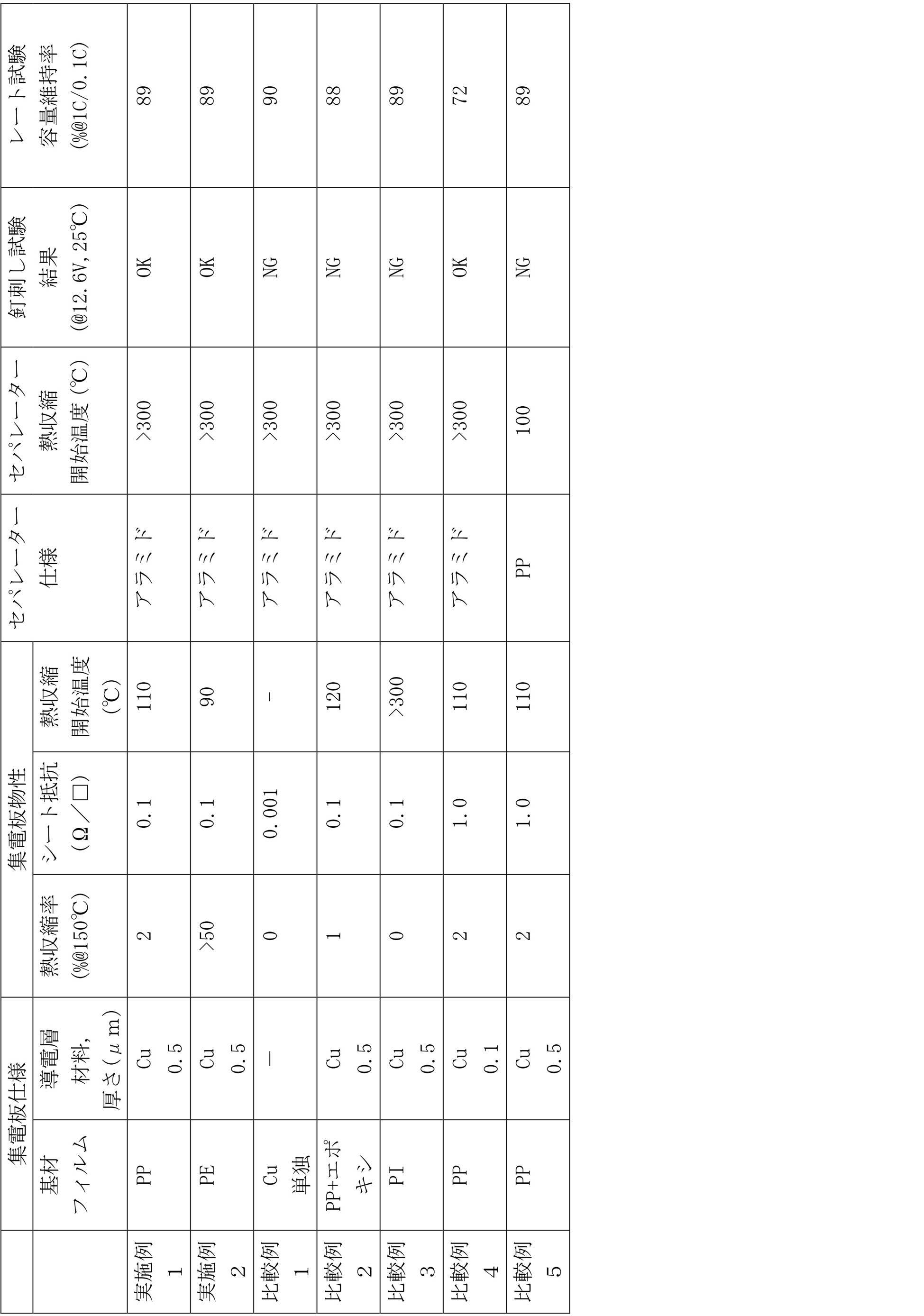
実施例1は基材フィルムとしてPPを用い、実施例2は基材フィルムとしてPEを用いて、それぞれの樹脂フィルムにCu層を形成して集電板としている。また、セパレーターにアラミドを用いた。
これら実施例1および2では、釘刺し試験の結果、釘短絡発熱時の集電板の熱収縮が大きいため、釘短絡電流を十分に抑えられた。また、セパレーターの熱収縮開始温度が高いため、集電板熱収縮後においてはセパレーターの熱損によるセル内部短絡を抑えることができた。また、セパレーターの耐熱性が高いため、集電板熱収縮前のセパレーターの熱損によるセル内部短絡を抑えることができた。
また、レート試験の結果から実施例1および2は、シート抵抗がCu箔単独の集電板を用いた比較例1と比べて遜色なく、放電レート特性の低下が抑えられている。
比較例1は、集電板としてCu箔を単独で用い、セパレーターにアラミドを用いた。したがって集電板のシート抵抗が低い。釘刺し試験の結果、集電板の熱収縮はほとんどないため短絡電流が大きく、釘刺し試験NGであった。
比較例2は、集電板としてPPフィルムにエポキシフィルムを積層した基材フィルム上にCu層を形成したものを用いた。セパレーターはアラミドである。比較例3は集電板としてPIフィルムにCu層を形成したものを用い、セパレーターにアラミドを用いた。これら比較例2および3では、集電板の熱収縮率が小さく、釘刺し後、釘と集電板との離隔が不十分なため、釘刺し試験NGとなった。
比較例4は、集電板にPPフィルムにCu層を形成したものを用い、セパレーターにアラミドを用いた。比較例4では、Cu層が薄く、集電板としてのシート抵抗が高い。このため放電レート特性(容量維持率)が実施例1および2、さらに他の比較例と比べて低かった。
比較例5は、集電板にPPフィルムにCu層を形成したものを用い、セパレーターにPPフィルムを用いた。比較例5では、セパレーターの熱収縮開始温度が低い。このため、釘刺し後、集電板が熱収縮する前またはほとんど同時に、発電要素内部の熱損が大きくなり、これにより内部短絡が起こり釘刺し試験NGであった。
以上の実施例および比較例から、樹脂フィルムにCu層を形成した集電板を用いることで、釘刺し試験において温度上昇を抑えられることが分かった。また、用いる集電板のシート抵抗が0.1Ω/□程度であればCu箔単独の集電板と同程度の容量維持率を得られることが分かった。
以上説明した実施形態(実施例含む)によれば、以下の効果を奏する。
(1)本実施形態の二次電池は、150℃における熱収縮率が2%以上の樹脂フィルム上に導電層を形成した集電板を用いる。これにより、導電体が外装体を貫通して侵入した場合でも、導電体が発熱すると、その熱で樹脂フィルムが熱収縮または溶融して、集電板と導電体との接触部分が離れるようになる。このため、集電板を介して導電体に流れ込む電流が減少し、導電体の発熱が抑えられる。さらに本実施形態では、セパレーターの熱収縮開始温度が集電板に使用している樹脂フィルムの熱収縮開始温度よりも高いものを用いている。これにより集電板の樹脂フィルムが熱収縮または溶融した時点では、セパレーターの熱損が発生しないかまたは非常に少ない状態に留まっている。そして、上記のように、集電板の樹脂フィルムが熱収縮または溶融した時点以降は、導電体や集電板の発熱が抑えられるため、セパレーターの熱損による内部短絡の広がりも抑えることができる。これらの結果、二次電池の導電体が侵入したような場合における二次電池の温度上昇を抑えることができる。
(2)また、本実施形態では、樹脂フィルム上に形成された導電層として金属層を用いた。これにより樹脂フィルム上に、抵抗の低い導電層を形成することができる。
(3)また、本実施形態では、集電板の抵抗を0.1Ω/□以下とする。これにより容量維持率を、金属のみの集電板を用いた二次電池と同様に高くすることができる。
(4)また、本実施形態では、好ましくは集電体として導電性樹脂からなる集電体を用いる。これにより、積層方向の電子伝導に影響を与えることなく、面方向の電気抵抗が高くなる。このため、導電体が外装体を突き抜けて発電要素内に侵入した場合に、集電体から導電体へ電流が流れ込むのを抑えることができる。
以上、本発明の実施形態に係る二次電池について説明したが、本発明は上述した実施形態に限定されない。本発明は特許請求の範囲に記載された構成に基づき様々な改変が可能であり、それらについても本発明の範疇である。
本出願は、2017年5月10日に出願された日本特許出願(特願2017-094061号)に基づいており、その開示内容は、参照され、全体として、組み入れられている。
1 二次電池、
10 発電要素、
11 集電体、
12 正極、
13 負極、
14a 双極型電極、
14b 単電池層、
15 セパレーター、
16 正極側集電板、
17 負極側集電板、
18 シール部、
20 外装体、
30 樹脂フィルム、
31 導電層。
10 発電要素、
11 集電体、
12 正極、
13 負極、
14a 双極型電極、
14b 単電池層、
15 セパレーター、
16 正極側集電板、
17 負極側集電板、
18 シール部、
20 外装体、
30 樹脂フィルム、
31 導電層。
Claims (4)
- 双極型電極を有する双極型二次電池であって、
セパレーターを介して前記双極型電極を積層した単位発電要素を積層した発電要素と、
前記単位発電要素の積層方向において前記発電要素の両端に配置され、前記発電要素に当接する集電板と、
を有し、
前記集電板は、150℃における熱収縮率が2%以上の樹脂フィルム上に導電層を形成したものからなり、
前記セパレーターの熱収縮開始温度が前記樹脂フィルムの熱収縮開始温度よりも高い、双極型二次電池。 - 前記樹脂フィルム上に形成された前記導電層が金属層からなる、請求項1に記載の双極型二次電池。
- 前記樹脂フィルム上に前記導電層を形成した前記集電板のシート抵抗は、0.1Ω/□以下である、請求項1または2に記載の双極型二次電池。
- 前記双極型電極は、樹脂集電体の一方の面に正極が形成され、前記一方の面に対向する他方の面に負極が形成されている、請求項1~3のいずれか1つに記載の双極型二次電池。
Priority Applications (3)
| Application Number | Priority Date | Filing Date | Title |
|---|---|---|---|
| EP18798508.0A EP3624243B1 (en) | 2017-05-10 | 2018-04-26 | Bipolar secondary battery |
| CN201880030625.9A CN110612630B (zh) | 2017-05-10 | 2018-04-26 | 双极型二次电池 |
| US16/611,900 US11075397B2 (en) | 2017-05-10 | 2018-04-26 | Bipolar secondary battery |
Applications Claiming Priority (2)
| Application Number | Priority Date | Filing Date | Title |
|---|---|---|---|
| JP2017-094061 | 2017-05-10 | ||
| JP2017094061A JP6917765B2 (ja) | 2017-05-10 | 2017-05-10 | 双極型二次電池 |
Publications (1)
| Publication Number | Publication Date |
|---|---|
| WO2018207643A1 true WO2018207643A1 (ja) | 2018-11-15 |
Family
ID=64105587
Family Applications (1)
| Application Number | Title | Priority Date | Filing Date |
|---|---|---|---|
| PCT/JP2018/017017 WO2018207643A1 (ja) | 2017-05-10 | 2018-04-26 | 双極型二次電池 |
Country Status (5)
| Country | Link |
|---|---|
| US (1) | US11075397B2 (ja) |
| EP (1) | EP3624243B1 (ja) |
| JP (1) | JP6917765B2 (ja) |
| CN (1) | CN110612630B (ja) |
| WO (1) | WO2018207643A1 (ja) |
Families Citing this family (1)
| Publication number | Priority date | Publication date | Assignee | Title |
|---|---|---|---|---|
| CN110660957B (zh) * | 2018-12-29 | 2020-12-04 | 宁德时代新能源科技股份有限公司 | 一种电极极片和电化学装置 |
Citations (6)
| Publication number | Priority date | Publication date | Assignee | Title |
|---|---|---|---|---|
| JP2009252548A (ja) | 2008-04-07 | 2009-10-29 | Toyota Motor Corp | 固体型電池 |
| WO2009131184A1 (ja) * | 2008-04-24 | 2009-10-29 | シャープ株式会社 | 非水系二次電池 |
| WO2010016432A1 (ja) * | 2008-08-08 | 2010-02-11 | シャープ株式会社 | 電池 |
| JP2016146270A (ja) * | 2015-02-06 | 2016-08-12 | 日産自動車株式会社 | 二次電池およびその製造方法 |
| JP2017094061A (ja) | 2015-11-26 | 2017-06-01 | 三星電子株式会社Samsung Electronics Co.,Ltd. | フレームアセンブリ及びこれを含む運動補助装置 |
| JP2018098206A (ja) * | 2016-12-14 | 2018-06-21 | 日産自動車株式会社 | 双極型二次電池 |
Family Cites Families (3)
| Publication number | Priority date | Publication date | Assignee | Title |
|---|---|---|---|---|
| JP2011034891A (ja) * | 2009-08-04 | 2011-02-17 | Nissan Motor Co Ltd | 非水電解質二次電池 |
| JP2013026057A (ja) * | 2011-07-22 | 2013-02-04 | Sharp Corp | 集電体および非水系二次電池 |
| JP6125265B2 (ja) * | 2012-05-07 | 2017-05-10 | 日東電工株式会社 | 積層型導電シート、その製造方法、集電体およびバイポーラ電池 |
-
2017
- 2017-05-10 JP JP2017094061A patent/JP6917765B2/ja active Active
-
2018
- 2018-04-26 WO PCT/JP2018/017017 patent/WO2018207643A1/ja unknown
- 2018-04-26 CN CN201880030625.9A patent/CN110612630B/zh active Active
- 2018-04-26 US US16/611,900 patent/US11075397B2/en active Active
- 2018-04-26 EP EP18798508.0A patent/EP3624243B1/en active Active
Patent Citations (6)
| Publication number | Priority date | Publication date | Assignee | Title |
|---|---|---|---|---|
| JP2009252548A (ja) | 2008-04-07 | 2009-10-29 | Toyota Motor Corp | 固体型電池 |
| WO2009131184A1 (ja) * | 2008-04-24 | 2009-10-29 | シャープ株式会社 | 非水系二次電池 |
| WO2010016432A1 (ja) * | 2008-08-08 | 2010-02-11 | シャープ株式会社 | 電池 |
| JP2016146270A (ja) * | 2015-02-06 | 2016-08-12 | 日産自動車株式会社 | 二次電池およびその製造方法 |
| JP2017094061A (ja) | 2015-11-26 | 2017-06-01 | 三星電子株式会社Samsung Electronics Co.,Ltd. | フレームアセンブリ及びこれを含む運動補助装置 |
| JP2018098206A (ja) * | 2016-12-14 | 2018-06-21 | 日産自動車株式会社 | 双極型二次電池 |
Non-Patent Citations (1)
| Title |
|---|
| See also references of EP3624243A4 |
Also Published As
| Publication number | Publication date |
|---|---|
| EP3624243B1 (en) | 2020-12-23 |
| US20200388875A1 (en) | 2020-12-10 |
| JP2018190656A (ja) | 2018-11-29 |
| EP3624243A1 (en) | 2020-03-18 |
| CN110612630B (zh) | 2021-03-23 |
| JP6917765B2 (ja) | 2021-08-11 |
| EP3624243A4 (en) | 2020-06-10 |
| CN110612630A (zh) | 2019-12-24 |
| US11075397B2 (en) | 2021-07-27 |
Similar Documents
| Publication | Publication Date | Title |
|---|---|---|
| JP5910164B2 (ja) | 非水電解質二次電池 | |
| KR101985041B1 (ko) | 내열 절연층을 갖는 세퍼레이터 | |
| KR101891013B1 (ko) | 전기 디바이스 | |
| KR101689496B1 (ko) | 비수 전해액계 이차 전지 | |
| JP6260335B2 (ja) | 双極型二次電池 | |
| CN110915023B (zh) | 用于二次电池的具有不对称结构的阻燃隔板 | |
| JP2010251197A (ja) | リチウムイオン電池 | |
| JP5434397B2 (ja) | 双極型電池用集電体 | |
| JP7475825B2 (ja) | リチウムイオン電池モジュール及び電池パック | |
| KR20160100348A (ko) | 전기 디바이스 | |
| JP2012043629A (ja) | 非水系電解液二次電池用セパレータ及び非水系電解液二次電池 | |
| KR101910721B1 (ko) | 전기 디바이스 | |
| WO2016181926A1 (ja) | リチウムイオン二次電池 | |
| WO2017018436A1 (ja) | リチウムイオン二次電池 | |
| US20240047692A1 (en) | Secondary battery and method for manufacturing the same | |
| WO2018180372A1 (ja) | 二次電池およびその製造方法 | |
| JP6843580B2 (ja) | リチウムイオン電池の製造方法 | |
| KR101634919B1 (ko) | 비수전해질 이차 전지 | |
| WO2018207643A1 (ja) | 双極型二次電池 | |
| WO2017204077A1 (ja) | 電池用電極、該電極を備えた電池および前記電極の製造方法 | |
| WO2018110554A1 (ja) | 双極型二次電池 | |
| JP2018098206A (ja) | 双極型二次電池 | |
| KR20230157243A (ko) | 전고체 전지 |
Legal Events
| Date | Code | Title | Description |
|---|---|---|---|
| 121 | Ep: the epo has been informed by wipo that ep was designated in this application |
Ref document number: 18798508 Country of ref document: EP Kind code of ref document: A1 |
|
| NENP | Non-entry into the national phase |
Ref country code: DE |
|
| ENP | Entry into the national phase |
Ref document number: 2018798508 Country of ref document: EP Effective date: 20191210 |