WO2018207332A1 - 燃焼排ガス浄化システムの運用方法 - Google Patents
燃焼排ガス浄化システムの運用方法 Download PDFInfo
- Publication number
- WO2018207332A1 WO2018207332A1 PCT/JP2017/017955 JP2017017955W WO2018207332A1 WO 2018207332 A1 WO2018207332 A1 WO 2018207332A1 JP 2017017955 W JP2017017955 W JP 2017017955W WO 2018207332 A1 WO2018207332 A1 WO 2018207332A1
- Authority
- WO
- WIPO (PCT)
- Prior art keywords
- boiler
- bypass
- fuel
- exhaust gas
- flue
- Prior art date
- Legal status (The legal status is an assumption and is not a legal conclusion. Google has not performed a legal analysis and makes no representation as to the accuracy of the status listed.)
- Ceased
Links
Images

Classifications
-
- F—MECHANICAL ENGINEERING; LIGHTING; HEATING; WEAPONS; BLASTING
- F23—COMBUSTION APPARATUS; COMBUSTION PROCESSES
- F23J—REMOVAL OR TREATMENT OF COMBUSTION PRODUCTS OR COMBUSTION RESIDUES; FLUES
- F23J15/00—Arrangements of devices for treating smoke or fumes
- F23J15/003—Arrangements of devices for treating smoke or fumes for supplying chemicals to fumes, e.g. using injection devices
-
- B—PERFORMING OPERATIONS; TRANSPORTING
- B01—PHYSICAL OR CHEMICAL PROCESSES OR APPARATUS IN GENERAL
- B01D—SEPARATION
- B01D53/00—Separation of gases or vapours; Recovering vapours of volatile solvents from gases; Chemical or biological purification of waste gases, e.g. engine exhaust gases, smoke, fumes, flue gases, aerosols
- B01D53/34—Chemical or biological purification of waste gases
- B01D53/74—General processes for purification of waste gases; Apparatus or devices specially adapted therefor
- B01D53/86—Catalytic processes
- B01D53/8621—Removing nitrogen compounds
- B01D53/8625—Nitrogen oxides
- B01D53/8631—Processes characterised by a specific device
-
- B—PERFORMING OPERATIONS; TRANSPORTING
- B01—PHYSICAL OR CHEMICAL PROCESSES OR APPARATUS IN GENERAL
- B01D—SEPARATION
- B01D53/00—Separation of gases or vapours; Recovering vapours of volatile solvents from gases; Chemical or biological purification of waste gases, e.g. engine exhaust gases, smoke, fumes, flue gases, aerosols
- B01D53/34—Chemical or biological purification of waste gases
- B01D53/74—General processes for purification of waste gases; Apparatus or devices specially adapted therefor
- B01D53/86—Catalytic processes
- B01D53/8696—Controlling the catalytic process
-
- B—PERFORMING OPERATIONS; TRANSPORTING
- B01—PHYSICAL OR CHEMICAL PROCESSES OR APPARATUS IN GENERAL
- B01D—SEPARATION
- B01D53/00—Separation of gases or vapours; Recovering vapours of volatile solvents from gases; Chemical or biological purification of waste gases, e.g. engine exhaust gases, smoke, fumes, flue gases, aerosols
- B01D53/34—Chemical or biological purification of waste gases
- B01D53/92—Chemical or biological purification of waste gases of engine exhaust gases
- B01D53/94—Chemical or biological purification of waste gases of engine exhaust gases by catalytic processes
- B01D53/9404—Removing only nitrogen compounds
- B01D53/9409—Nitrogen oxides
- B01D53/9431—Processes characterised by a specific device
-
- F—MECHANICAL ENGINEERING; LIGHTING; HEATING; WEAPONS; BLASTING
- F23—COMBUSTION APPARATUS; COMBUSTION PROCESSES
- F23C—METHODS OR APPARATUS FOR COMBUSTION USING FLUID FUEL OR SOLID FUEL SUSPENDED IN A CARRIER GAS OR AIR
- F23C1/00—Combustion apparatus specially adapted for combustion of two or more kinds of fuel simultaneously or alternately, at least one kind of fuel being either a fluid fuel or a solid fuel suspended in a carrier gas or air
- F23C1/02—Combustion apparatus specially adapted for combustion of two or more kinds of fuel simultaneously or alternately, at least one kind of fuel being either a fluid fuel or a solid fuel suspended in a carrier gas or air lump and liquid fuel
-
- F—MECHANICAL ENGINEERING; LIGHTING; HEATING; WEAPONS; BLASTING
- F23—COMBUSTION APPARATUS; COMBUSTION PROCESSES
- F23J—REMOVAL OR TREATMENT OF COMBUSTION PRODUCTS OR COMBUSTION RESIDUES; FLUES
- F23J15/00—Arrangements of devices for treating smoke or fumes
- F23J15/006—Layout of treatment plant
-
- B—PERFORMING OPERATIONS; TRANSPORTING
- B01—PHYSICAL OR CHEMICAL PROCESSES OR APPARATUS IN GENERAL
- B01D—SEPARATION
- B01D2258/00—Sources of waste gases
- B01D2258/02—Other waste gases
- B01D2258/0283—Flue gases
-
- F—MECHANICAL ENGINEERING; LIGHTING; HEATING; WEAPONS; BLASTING
- F23—COMBUSTION APPARATUS; COMBUSTION PROCESSES
- F23J—REMOVAL OR TREATMENT OF COMBUSTION PRODUCTS OR COMBUSTION RESIDUES; FLUES
- F23J2215/00—Preventing emissions
- F23J2215/10—Nitrogen; Compounds thereof
-
- F—MECHANICAL ENGINEERING; LIGHTING; HEATING; WEAPONS; BLASTING
- F23—COMBUSTION APPARATUS; COMBUSTION PROCESSES
- F23J—REMOVAL OR TREATMENT OF COMBUSTION PRODUCTS OR COMBUSTION RESIDUES; FLUES
- F23J2219/00—Treatment devices
- F23J2219/10—Catalytic reduction devices
-
- F—MECHANICAL ENGINEERING; LIGHTING; HEATING; WEAPONS; BLASTING
- F23—COMBUSTION APPARATUS; COMBUSTION PROCESSES
- F23J—REMOVAL OR TREATMENT OF COMBUSTION PRODUCTS OR COMBUSTION RESIDUES; FLUES
- F23J2900/00—Special arrangements for conducting or purifying combustion fumes; Treatment of fumes or ashes
- F23J2900/11001—Conducting systems with a gas flow bypass from main flue to an auxiliary flue
-
- F—MECHANICAL ENGINEERING; LIGHTING; HEATING; WEAPONS; BLASTING
- F23—COMBUSTION APPARATUS; COMBUSTION PROCESSES
- F23L—SUPPLYING AIR OR NON-COMBUSTIBLE LIQUIDS OR GASES TO COMBUSTION APPARATUS IN GENERAL ; VALVES OR DAMPERS SPECIALLY ADAPTED FOR CONTROLLING AIR SUPPLY OR DRAUGHT IN COMBUSTION APPARATUS; INDUCING DRAUGHT IN COMBUSTION APPARATUS; TOPS FOR CHIMNEYS OR VENTILATING SHAFTS; TERMINALS FOR FLUES
- F23L15/00—Heating of air supplied for combustion
- F23L15/02—Arrangements of regenerators
-
- F—MECHANICAL ENGINEERING; LIGHTING; HEATING; WEAPONS; BLASTING
- F23—COMBUSTION APPARATUS; COMBUSTION PROCESSES
- F23N—REGULATING OR CONTROLLING COMBUSTION
- F23N2237/00—Controlling
- F23N2237/20—Controlling one or more bypass conduits
-
- Y—GENERAL TAGGING OF NEW TECHNOLOGICAL DEVELOPMENTS; GENERAL TAGGING OF CROSS-SECTIONAL TECHNOLOGIES SPANNING OVER SEVERAL SECTIONS OF THE IPC; TECHNICAL SUBJECTS COVERED BY FORMER USPC CROSS-REFERENCE ART COLLECTIONS [XRACs] AND DIGESTS
- Y02—TECHNOLOGIES OR APPLICATIONS FOR MITIGATION OR ADAPTATION AGAINST CLIMATE CHANGE
- Y02E—REDUCTION OF GREENHOUSE GAS [GHG] EMISSIONS, RELATED TO ENERGY GENERATION, TRANSMISSION OR DISTRIBUTION
- Y02E20/00—Combustion technologies with mitigation potential
- Y02E20/34—Indirect CO2mitigation, i.e. by acting on non CO2directly related matters of the process, e.g. pre-heating or heat recovery
Definitions
- the present invention relates to a method for operating a combustion exhaust gas purification system. More specifically, the present invention can increase the temperature of the denitration device more uniformly and in a shorter time while suppressing the adhesion of unburned oil fuel to the denitration catalyst at the time of boiler startup due to oil combustion.
- the present invention relates to a method for operating a combustion exhaust gas purification system.
- Thermal power plants perform daily start / stop (DDS) operation, weekend start / stop (WSS) operation, etc., depending on power demand. Since coal has low combustibility, coal cannot be sufficiently burned unless conditions such as the temperature inside the boiler furnace are established. Therefore, in coal-fired boilers, oil oil with high combustibility such as light oil and heavy oil is supplied to the boiler furnace to start combustion. There are cases where switching from fuel to coal fuel is performed (Patent Documents 1 and 2, etc.).
- Patent Document 3 discloses a method for removing nitrogen oxides by passing flue gas exiting from a combustion device through an ammonia reduction denitration device.
- an ammonia reduction denitration device such as immediately after the start of the combustion device does not function sufficiently, a treatment gas containing unreacted nitrogen oxides from the denitration device is passed through the bypass.
- the NO in the process gas is oxidized to NO 2 and / or N 2 O 5 and then adsorbed to remove unreacted nitrogen oxides
- the ammonia reduction denitration apparatus is fully functional.
- Disclosed is a method for reducing nitrogen oxides in combustion exhaust gas, characterized in that the bypass is closed.
- Patent Document 4 connects an inlet flue for guiding an untreated gas to a denitration device and an outlet flue for guiding a processing gas, and denitrifies nitrogen oxides by ammonia from an ammonia injection pipe.
- a denitration apparatus is disclosed, characterized in that a circulation duct is provided in at least one of the inlet flue and the outlet flue, and dehumidifying means for removing moisture in the flue is disposed in the middle of the circulation duct. Yes.
- An object of the present invention is a combustion exhaust gas capable of increasing the temperature of a denitration device more uniformly and in a shorter time while suppressing adhesion of unburned oil fuel to a denitration catalyst at the time of boiler start-up due to oil combustion It is to provide a method for operating the purification system.
- a boiler capable of burning oil fuel and coal fuel simultaneously or by switching, a denitration device having a reducing agent injector and a catalytic reactor, an inlet flue for guiding combustion exhaust gas discharged from the boiler to the denitration device, denitration
- a flue gas purification system comprising an outlet flue that leads combustion exhaust gas from the apparatus, a bypass that can bypass the denitration device from the inlet flue to the outlet flue and lead flue gas, and a bypass damper, Open the bypass damper, burn the oil fuel in the boiler that is not yet suitable for coal combustion, and let the combustion exhaust gas discharged from the boiler flow separately into the denitration device and the bypass,
- the boiler is in a state suitable for coal combustion, switch from oil fuel to coal fuel, burn the coal fuel in the boiler, Close the bypass damper after switching from oil fuel to coal fuel, And injecting a reducing agent when the catalytic reactor is in a state suitable for the denitration reaction, Operation method of combustion exhaust gas purification system.
- the temperature of the denitration device can be made more uniform and more uniform as compared with the conventional operation method, while suppressing the adhesion of unburned oil fuel to the denitration catalyst at the time of boiler startup due to oil combustion. It can be raised in a short time. Since the temperature of the denitration apparatus can be increased uniformly, distortion of each part of the denitration apparatus, spots of the denitration reaction, and other problems that may occur due to temperature differences can be reduced. Since the temperature of the denitration device can be raised in a short time, the denitration treatment of the combustion exhaust gas can be started without delaying as much as the difference from the start of the boiler.
- the combustion exhaust gas purification system shown in FIG. 1 includes a boiler 1 capable of burning oil fuel and coal fuel simultaneously or by switching, a denitration apparatus having a reducing agent injector 3 and a catalytic reactor 5, and combustion discharged from the boiler 1.
- An inlet flue 12 that leads the exhaust gas to the denitration device, an outlet flue 13 that leads the combustion exhaust gas from the denitration device, a bypass 11 that can bypass the denitration device from the inlet flue to the outlet flue and guide the combustion exhaust gas, and a bypass damper 4 is provided.
- the denitration apparatus has a reducing agent injector 3 and a catalytic reactor 5.
- a reducing agent such as ammonia is injected into the inlet flue 12.
- the mixed gas of the combustion exhaust gas and the reducing agent is guided to the catalytic reactor 5 in which the catalyst layer 6 is installed.
- the NO x reduction reaction proceeds.
- the temperature of the catalyst layer is still low, and the NO x reduction reaction does not proceed much even if a reducing agent is injected.
- an ammonium sulfate production reaction or the like may be dominant over a NO x reduction reaction.
- the denitration device is heated by the thermal energy of the combustion exhaust gas, and the temperature of the catalyst layer rises.
- rapid heating causes temperature non-uniformity and may cause problems such as distortion in each part of the denitration device.
- the temperature of the denitration apparatus can be increased uniformly and in a short time by the method described later.
- the flue gas passing through the catalytic reactor is led to the outlet flue 13.
- the thermal energy of the combustion exhaust gas can be used to warm the air with the air preheater 8.
- the combustion exhaust gas can be released to the atmosphere by the chimney 10.
- an electrostatic precipitator, a desulfurizer, a de-CO 2 device, and / or other devices may be further installed.
- the dampers 2 and 7 are respectively installed at the inlet and the outlet of the denitration device. However, when the amount of combustion exhaust gas passing through the denitration device can be adjusted by the bypass damper 4, the dampers 2 and 7 are installed. It does not have to be installed.
- the denitration device inlet damper 2 and the denitration device outlet damper 7 are preferably driven by an electric actuator. Further, the denitration device inlet damper 2 and the denitration device outlet damper 7 are preferably proportional control type dampers. The amount of combustion exhaust gas passing through the denitration device can be adjusted by changing the opening degree of the denitration device inlet damper 2 or the denitration device outlet damper 7.
- the bypass 11 is a flow path that can guide the combustion exhaust gas from the inlet flue 12 to the outlet flue 13 by bypassing the denitration device.
- a bypass damper 4 is installed in the bypass 11.
- the bypass damper 4 is preferably driven by a pneumatic actuator.
- the bypass damper 4 is preferably an on / off control type damper.
- the method of the present invention first opens the bypass damper 4, the denitration device inlet damper 2, and the denitration device outlet damper 7. Then, oil fuel is burned in the boiler furnace 14.
- the startup boiler has a low temperature of the furnace 14 and is not yet suitable for coal combustion, but oil fuel is highly combustible and can be burned even at low temperatures.
- the combustion exhaust gas generated by oil combustion at a low temperature may contain unburned components (oil mist or the like) that may deteriorate the denitration catalyst.
- the combustion exhaust gas discharged from the boiler is divided into a denitration device and a bypass during oil combustion.
- the ratio of the amount of flue gas flowing through the bypass to the amount of flue gas flowing through the denitration device is preferably 60/40 to 95/5, more preferably 70/30 to 90/10.
- the time from the start of the boiler to the start of the injection of the reducing agent that is, the time from the start of the boiler to the start of the NO x reduction reaction can be greatly reduced as compared with the conventional method.
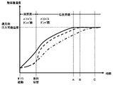
- Example 1 The solid line in FIG. 2 shows an example of the temperature change of the catalyst layer when the operation method of the present invention is performed in the combustion exhaust gas purification system shown in FIG.
- the temperature of the catalyst layer increased at a substantially constant rate from the boiler startup temperature to the temperature at which the reducing agent could be injected. Even when the bypass damper was closed after fuel switching (approximately 200 minutes after the boiler started), there was no sudden change in the rate of temperature rise of the catalyst layer. When about 800 minutes had elapsed since the start of the boiler (A), the catalyst layer reached a temperature at which ammonia could be injected.
- Comparative Example 1 In the combustion exhaust gas purification system shown in FIG. 1, the broken line in FIG. 2 first starts the boiler by oil combustion with the bypass damper 4 opened and the denitration apparatus inlet damper 2 and denitration apparatus outlet damper 7 closed.
- the temperature change of the catalyst layer when the operation of closing the bypass damper and simultaneously opening the denitration apparatus inlet damper 2 and the denitration apparatus outlet damper 7 after fuel switching (when about 200 minutes have elapsed since the start of the boiler) is shown.
- the temperature of the catalyst layer slightly increased due to heat conduction in the ducts.
- Comparative Example 2 In the combustion exhaust gas purification system shown in FIG. 1, the one-dot chain line in FIG. 2 starts the boiler by oil combustion with the bypass damper 4 opened and the denitration apparatus inlet damper 2 and denitration apparatus outlet damper 7 closed.
- the temperature of the catalyst layer when the operation of gradually opening the denitration device inlet damper 2 and the denitration device outlet damper 7 at the same time while gradually closing the bypass damper after fuel switching (when about 200 minutes have passed since the start of the boiler) Showing change.
- the temperature of the catalyst layer slightly increased due to heat conduction in the ducts.
- the bypass damper 4 is gradually closed over 200 minutes, and at the same time, the NOx removal device inlet damper 2 and the NOx removal outlet damper 7 are gradually opened over 200 minutes.
- the temperature rose at a constant rate.
- the catalyst layer reached a temperature at which ammonia could be injected.
Landscapes
- Engineering & Computer Science (AREA)
- Chemical & Material Sciences (AREA)
- Environmental & Geological Engineering (AREA)
- Chemical Kinetics & Catalysis (AREA)
- General Chemical & Material Sciences (AREA)
- Mechanical Engineering (AREA)
- General Engineering & Computer Science (AREA)
- Biomedical Technology (AREA)
- Health & Medical Sciences (AREA)
- Analytical Chemistry (AREA)
- Oil, Petroleum & Natural Gas (AREA)
- Combustion & Propulsion (AREA)
- Exhaust Gas Treatment By Means Of Catalyst (AREA)
Abstract
Description
バイパスダンパを開いて、石炭燃焼に未だ適さない状態のボイラにて油燃料を燃やし、ボイラから排出される燃焼排ガスが脱硝装置とバイパスとに分かれて流れるようにし、
ボイラが石炭燃焼に適した状態になったときに、油燃料から石炭燃料に切り替えて、ボイラにて石炭燃料を燃やし、
油燃料から石炭燃料に切り替えた後にバイパスダンパを閉じ、
そして、触媒反応器が脱硝反応に適した状態になったときに、還元剤を注入することを含む、
燃焼排ガス浄化システムの運用方法。
〔3〕バイパスダンパがオン・オフ制御式ダンパである、〔1〕に記載の方法。
〔4〕脱硝装置とバイパスとに5:95~40:60の割合で燃焼排ガスが分かれて流れる、〔1〕に記載の方法。
次いで、触媒反応器が脱硝反応に適した状態になったときに、還元剤の注入を始める。本発明の方法によると、ボイラ起動から還元剤の注入の開始、すなわちボイラ起動からNOxの還元反応の開始までの時間を、従来の方法に比べて大幅に短縮することができる。
図2中の実線は、図1に示す燃焼排ガス浄化システムにおいて、本発明の運用方法を行った際の触媒層の温度変化の一例を示す。ボイラ起動時温度から還元剤注入可能温度までほぼ一定の速度で触媒層の温度が上昇した。燃料切り換え後(ボイラ起動から約200分間経過時)にバイパスダンパを閉じても、触媒層の温度上昇の速度に急激な変化が無かった。ボイラ起動から約800分間経過した時(A)に触媒層はアンモニア注入が可能な温度になった。
図2中の破線は、図1に示す燃焼排ガス浄化システムにおいて、先ず、バイパスダンパ4を開き且つ脱硝装置入口ダンパ2および脱硝装置出口ダンパ7を閉じた状態で、ボイラを油燃焼で起動し、燃料切り換え後(ボイラ起動から約200分間経過時)にバイパスダンパを閉じ、同時に脱硝装置入口ダンパ2および脱硝装置出口ダンパ7を開くという運用を行った際の触媒層の温度変化を示す。起動直後、ダクトなどを熱伝導して触媒層の温度が若干上昇した。燃料切り換え後(ボイラ起動から約200分間経過時)にバイパスダンパ4を閉じ、同時に脱硝装置入口ダンパ2および脱硝装置出口ダンパ7を開くと、燃焼排ガスからの熱伝達(対流伝熱)により触媒層の温度が急激に上昇した。このとき、脱硝装置各部に大きな温度差(ヒートショック)が発生した。ボイラ起動から約900分間経過した時(B)に触媒層はアンモニア注入が可能な温度になった。
図2中の一点鎖線は、図1に示す燃焼排ガス浄化システムにおいて、先ず、バイパスダンパ4を開き且つ脱硝装置入口ダンパ2および脱硝装置出口ダンパ7を閉じた状態で、ボイラを油燃焼で起動し、燃料切り換え後(ボイラ起動から約200分間経過時)にバイパスダンパを徐々に閉じながら、同時に脱硝装置入口ダンパ2および脱硝装置出口ダンパ7を徐々に開くという運用を行った際の触媒層の温度変化を示す。起動直後、ダクトなどを熱伝導して触媒層の温度が若干上昇した。燃料切り換え後(ボイラ起動から約200分間経過時)にバイパスダンパ4を200分間かけて徐々に閉じ、同時に脱硝装置入口ダンパ2および脱硝装置出口ダンパ7を200分間かけて徐々に開くと、触媒層の温度が一定速度で上昇した。ボイラ起動から約1200分間経過した時(C)に触媒層はアンモニア注入が可能な温度になった。
2:脱硝装置入口ダンパ
3:還元剤注入器
4:バイパスダンパ
5:触媒反応器
6:触媒層
7:脱硝装置出口ダンパ
8:空気予熱器
9:誘引ファン
10:煙突
11:バイパス
12:入口煙道
13:出口煙道
14:火炉
Claims (4)
- 油燃料および石炭燃料を同時にまたは切り替えて燃やすことのできるボイラ、還元剤注入器と触媒反応器とを有する脱硝装置、ボイラから排出される燃焼排ガスを脱硝装置へ導く入口煙道、脱硝装置から燃焼排ガスを導く出口煙道、入口煙道から出口煙道に脱硝装置を迂回して燃焼排ガスを導くことのできるバイパス、およびバイパスダンパを具備する燃焼排ガス浄化システムにおいて、
バイパスダンパを開いて、石炭燃焼に未だ適さない状態のボイラにて油燃料を燃やし、ボイラから排出される燃焼排ガスが脱硝装置とバイパスとに分かれて流れるようにし、
ボイラが石炭燃焼に適した状態になったときに、油燃料から石炭燃料に切り替えて、ボイラにて石炭燃料を燃やし、
油燃料から石炭燃料に切り替えた後にバイパスダンパを閉じ、
そして、触媒反応器が脱硝反応に適した状態になったときに、還元剤を注入することを含む、
燃焼排ガス浄化システムの運用方法。 - バイパスダンパを空気式アクチュエータで駆動させる、請求項1に記載の方法。
- バイパスダンパがオン・オフ制御式ダンパである、請求項1に記載の方法。
- 脱硝装置とバイパスとに5:95~40:60の割合で燃焼排ガスが分かれて流れる、請求項1に記載の方法。
Priority Applications (3)
| Application Number | Priority Date | Filing Date | Title |
|---|---|---|---|
| US16/611,652 US11441774B2 (en) | 2017-05-11 | 2017-05-11 | Method for operating flue gas purification system |
| KR1020197033006A KR102334460B1 (ko) | 2017-05-11 | 2017-05-11 | 연소 배기 가스 정화 시스템의 운용 방법 |
| PCT/JP2017/017955 WO2018207332A1 (ja) | 2017-05-11 | 2017-05-11 | 燃焼排ガス浄化システムの運用方法 |
Applications Claiming Priority (1)
| Application Number | Priority Date | Filing Date | Title |
|---|---|---|---|
| PCT/JP2017/017955 WO2018207332A1 (ja) | 2017-05-11 | 2017-05-11 | 燃焼排ガス浄化システムの運用方法 |
Publications (1)
| Publication Number | Publication Date |
|---|---|
| WO2018207332A1 true WO2018207332A1 (ja) | 2018-11-15 |
Family
ID=64105441
Family Applications (1)
| Application Number | Title | Priority Date | Filing Date |
|---|---|---|---|
| PCT/JP2017/017955 Ceased WO2018207332A1 (ja) | 2017-05-11 | 2017-05-11 | 燃焼排ガス浄化システムの運用方法 |
Country Status (3)
| Country | Link |
|---|---|
| US (1) | US11441774B2 (ja) |
| KR (1) | KR102334460B1 (ja) |
| WO (1) | WO2018207332A1 (ja) |
Cited By (4)
| Publication number | Priority date | Publication date | Assignee | Title |
|---|---|---|---|---|
| CN109340737A (zh) * | 2018-11-19 | 2019-02-15 | 哈尔滨红光锅炉总厂有限责任公司 | 一种可用于scr脱硝的角管锅炉 |
| CN112460618A (zh) * | 2020-12-03 | 2021-03-09 | 昆山市三维换热器有限公司 | 全负荷脱硝系统及其控制方法 |
| CN116518396A (zh) * | 2023-05-10 | 2023-08-01 | 扬州正宇锅炉有限公司 | 一种大型生物质半气化模块组装水管锅炉 |
| CN120679341A (zh) * | 2025-06-07 | 2025-09-23 | 国能龙源环保有限公司 | 基于脱硝系统的喷氨方法及装置 |
Families Citing this family (4)
| Publication number | Priority date | Publication date | Assignee | Title |
|---|---|---|---|---|
| CN112535947A (zh) * | 2020-05-22 | 2021-03-23 | 河南亿水源净水材料科技有限公司 | 一种高效脱硝的方法 |
| CN111589301A (zh) * | 2020-05-29 | 2020-08-28 | 广东电科院能源技术有限责任公司 | 燃煤电厂scr脱硝性能预测方法、装置、设备和存储介质 |
| CN112619413A (zh) * | 2020-12-24 | 2021-04-09 | 西安大唐电力设计研究院有限公司 | 一种链条炉脱硝系统 |
| CN114470980B (zh) * | 2022-01-07 | 2023-06-27 | 呼伦贝尔安泰热电有限责任公司海拉尔热电厂 | 一种便于调节流量的锅炉旁路烟道组件及其使用方法 |
Citations (7)
| Publication number | Priority date | Publication date | Assignee | Title |
|---|---|---|---|---|
| JPS60255523A (ja) * | 1984-05-30 | 1985-12-17 | Nippon Denso Co Ltd | カ−エアコン制御装置 |
| JPS6198523U (ja) * | 1984-11-30 | 1986-06-24 | ||
| JPS62186926A (ja) * | 1986-02-12 | 1987-08-15 | Babcock Hitachi Kk | 脱硝装置 |
| JPH05340238A (ja) * | 1992-06-05 | 1993-12-21 | Mazda Motor Corp | 排気ガス浄化装置 |
| JPH10159542A (ja) * | 1996-11-29 | 1998-06-16 | Mitsubishi Heavy Ind Ltd | 脱硝装置付きディーゼル機関 |
| JP2001129353A (ja) * | 1999-11-01 | 2001-05-15 | Babcock Hitachi Kk | 排ガス処理装置のガス流路切替え方法 |
| JP2007314139A (ja) * | 2006-05-29 | 2007-12-06 | Toyota Motor Corp | 冷却装置 |
Family Cites Families (13)
| Publication number | Priority date | Publication date | Assignee | Title |
|---|---|---|---|---|
| US4353207A (en) * | 1980-08-20 | 1982-10-12 | Westinghouse Electric Corp. | Apparatus for removing NOx and for providing better plant efficiency in simple cycle combustion turbine plants |
| JPS62106825A (ja) | 1985-11-05 | 1987-05-18 | Babcock Hitachi Kk | 脱硝装置 |
| US5275554A (en) | 1990-08-31 | 1994-01-04 | Power-Flame, Inc. | Combustion system with low NOx adapter assembly |
| JP3202419B2 (ja) | 1993-06-30 | 2001-08-27 | 三菱重工業株式会社 | 燃焼排ガス中の窒素酸化物の低減方法 |
| FR2728301B1 (fr) * | 1994-12-19 | 1997-03-14 | Peugeot | Dispositif de traitement des gaz d'echappement d'un moteur a allumage commande comportant un corps catalyseur et un adsorbeur d'hydrocarbures disposes a l'interieur d'un collecteur d'echappement |
| US5603215A (en) * | 1995-03-23 | 1997-02-18 | Engelhard Corporation | Method and apparatus for treatment of exhaust streams |
| US5943865A (en) * | 1998-12-03 | 1999-08-31 | Cohen; Mitchell B. | Reheating flue gas for selective catalytic systems |
| JP4938945B2 (ja) | 2001-09-12 | 2012-05-23 | 三菱重工業株式会社 | 脱硝装置および脱硝方法 |
| JP2006125808A (ja) | 2004-11-01 | 2006-05-18 | Babcock Hitachi Kk | 燃焼装置とその燃料燃焼方法 |
| JP4386279B2 (ja) | 2004-12-10 | 2009-12-16 | バブコック日立株式会社 | バーナの運転方法 |
| US7481987B2 (en) * | 2005-09-15 | 2009-01-27 | Solvay Chemicals | Method of removing sulfur trioxide from a flue gas stream |
| KR101072578B1 (ko) | 2009-09-07 | 2011-10-11 | 한국전력공사 | 유동층 연소 보일러의 기동 연소제어장치 |
| KR101843818B1 (ko) | 2016-07-18 | 2018-03-30 | 성진계장 주식회사 | 공조 및 소방 겸용 댐퍼 구동기 및 이것을 이용한 제어 방법 |
-
2017
- 2017-05-11 WO PCT/JP2017/017955 patent/WO2018207332A1/ja not_active Ceased
- 2017-05-11 KR KR1020197033006A patent/KR102334460B1/ko not_active Expired - Fee Related
- 2017-05-11 US US16/611,652 patent/US11441774B2/en active Active
Patent Citations (7)
| Publication number | Priority date | Publication date | Assignee | Title |
|---|---|---|---|---|
| JPS60255523A (ja) * | 1984-05-30 | 1985-12-17 | Nippon Denso Co Ltd | カ−エアコン制御装置 |
| JPS6198523U (ja) * | 1984-11-30 | 1986-06-24 | ||
| JPS62186926A (ja) * | 1986-02-12 | 1987-08-15 | Babcock Hitachi Kk | 脱硝装置 |
| JPH05340238A (ja) * | 1992-06-05 | 1993-12-21 | Mazda Motor Corp | 排気ガス浄化装置 |
| JPH10159542A (ja) * | 1996-11-29 | 1998-06-16 | Mitsubishi Heavy Ind Ltd | 脱硝装置付きディーゼル機関 |
| JP2001129353A (ja) * | 1999-11-01 | 2001-05-15 | Babcock Hitachi Kk | 排ガス処理装置のガス流路切替え方法 |
| JP2007314139A (ja) * | 2006-05-29 | 2007-12-06 | Toyota Motor Corp | 冷却装置 |
Cited By (5)
| Publication number | Priority date | Publication date | Assignee | Title |
|---|---|---|---|---|
| CN109340737A (zh) * | 2018-11-19 | 2019-02-15 | 哈尔滨红光锅炉总厂有限责任公司 | 一种可用于scr脱硝的角管锅炉 |
| CN112460618A (zh) * | 2020-12-03 | 2021-03-09 | 昆山市三维换热器有限公司 | 全负荷脱硝系统及其控制方法 |
| CN116518396A (zh) * | 2023-05-10 | 2023-08-01 | 扬州正宇锅炉有限公司 | 一种大型生物质半气化模块组装水管锅炉 |
| CN116518396B (zh) * | 2023-05-10 | 2024-01-19 | 扬州正宇锅炉有限公司 | 一种大型生物质半气化模块组装水管锅炉 |
| CN120679341A (zh) * | 2025-06-07 | 2025-09-23 | 国能龙源环保有限公司 | 基于脱硝系统的喷氨方法及装置 |
Also Published As
| Publication number | Publication date |
|---|---|
| KR102334460B1 (ko) | 2021-12-02 |
| KR20190134755A (ko) | 2019-12-04 |
| US20200149741A1 (en) | 2020-05-14 |
| US11441774B2 (en) | 2022-09-13 |
Similar Documents
| Publication | Publication Date | Title |
|---|---|---|
| WO2018207332A1 (ja) | 燃焼排ガス浄化システムの運用方法 | |
| JP7207810B2 (ja) | ボイラの効率を向上させるための方法及びシステム | |
| US4353207A (en) | Apparatus for removing NOx and for providing better plant efficiency in simple cycle combustion turbine plants | |
| US8211391B2 (en) | Biomass boiler SCR NOx and CO reduction system | |
| KR101057342B1 (ko) | 가속 선택적 촉매 환원법을 이용한 저온 탈질 효율 증가 및 가시매연 제거 시스템 | |
| CN102187078A (zh) | 用于热回收蒸汽发生系统的减排系统 | |
| RU2543096C1 (ru) | СПОСОБ И УСТРОЙСТВО ДЛЯ СЕЛЕКТИВНОГО КАТАЛИТИЧЕСКОГО ВОССТАНОВЛЕНИЯ NOx В ЭНЕРГЕТИЧЕСКОМ КОТЛЕ | |
| JP7420941B2 (ja) | 蒸気ボイラシステムを作動させるための配置構成及び方法 | |
| CN204400906U (zh) | 煤粉热解污染物处理系统及锅炉燃烧系统 | |
| CN110252139B (zh) | 一种scr脱硝系统及加热装置和脱硝方法 | |
| CN114278948B (zh) | 一种退役风电叶片的处理装置及方法 | |
| CN112610964A (zh) | 一种危险废物焚烧烟气的scr处理系统及方法 | |
| CN112892205A (zh) | 一种用煤粉炉加热scr脱硝烟气装置及其方法 | |
| JP2011125766A (ja) | 排ガス処理装置 | |
| KR101944291B1 (ko) | 산업용 보일러의 백연 및 유해물질 저감장치 | |
| CN214581129U (zh) | 一种危险废物焚烧烟气的scr处理系统 | |
| CN106979529B (zh) | 燃烧处理设备 | |
| JP2010249407A (ja) | 石炭焚きボイラおよびそれを備えたプラント | |
| JPH0367728B2 (ja) | ||
| JP5881545B2 (ja) | 石炭焚きボイラに用いられる脱硝装置 | |
| JPS62183859A (ja) | 石炭焚ボイラからの排ガス処理方法 | |
| CN111964026B (zh) | 一种生物质锅炉环保设备正压式热风维保系统及方法 | |
| CN121891882A (zh) | 耦合火电灵活调峰的烟气污染物治理系统及其控制方法 | |
| JPS583730B2 (ja) | 排ガスの処理方法 | |
| JP2007105675A (ja) | 排ガス処理装置の運転方法及びボイラ装置 |
Legal Events
| Date | Code | Title | Description |
|---|---|---|---|
| 121 | Ep: the epo has been informed by wipo that ep was designated in this application |
Ref document number: 17909034 Country of ref document: EP Kind code of ref document: A1 |
|
| ENP | Entry into the national phase |
Ref document number: 20197033006 Country of ref document: KR Kind code of ref document: A |
|
| NENP | Non-entry into the national phase |
Ref country code: DE |
|
| 122 | Ep: pct application non-entry in european phase |
Ref document number: 17909034 Country of ref document: EP Kind code of ref document: A1 |
|
| NENP | Non-entry into the national phase |
Ref country code: JP |