WO2018199260A1 - 遠隔操作端末の置き忘れ防止装置、遠隔操作端末、および遠隔操作端末の置き忘れ防止システム - Google Patents
遠隔操作端末の置き忘れ防止装置、遠隔操作端末、および遠隔操作端末の置き忘れ防止システム Download PDFInfo
- Publication number
- WO2018199260A1 WO2018199260A1 PCT/JP2018/017065 JP2018017065W WO2018199260A1 WO 2018199260 A1 WO2018199260 A1 WO 2018199260A1 JP 2018017065 W JP2018017065 W JP 2018017065W WO 2018199260 A1 WO2018199260 A1 WO 2018199260A1
- Authority
- WO
- WIPO (PCT)
- Prior art keywords
- unit
- remote operation
- operation terminal
- remote control
- pto
- Prior art date
Links
- 230000005540 biological transmission Effects 0.000 claims abstract description 43
- 230000002265 prevention Effects 0.000 claims description 38
- 230000006854 communication Effects 0.000 claims description 24
- 238000001514 detection method Methods 0.000 claims description 5
- 230000008054 signal transmission Effects 0.000 claims description 4
- 239000003921 oil Substances 0.000 description 9
- 230000004048 modification Effects 0.000 description 6
- 238000012986 modification Methods 0.000 description 6
- 230000008602 contraction Effects 0.000 description 4
- 239000000758 substrate Substances 0.000 description 4
- 230000000694 effects Effects 0.000 description 3
- 238000009434 installation Methods 0.000 description 3
- 238000010586 diagram Methods 0.000 description 2
- WHXSMMKQMYFTQS-UHFFFAOYSA-N Lithium Chemical compound [Li] WHXSMMKQMYFTQS-UHFFFAOYSA-N 0.000 description 1
- 230000007175 bidirectional communication Effects 0.000 description 1
- 230000002457 bidirectional effect Effects 0.000 description 1
- 239000010720 hydraulic oil Substances 0.000 description 1
- 230000001771 impaired effect Effects 0.000 description 1
- 239000004973 liquid crystal related substance Substances 0.000 description 1
- 229910052744 lithium Inorganic materials 0.000 description 1
Images

Classifications
-
- B—PERFORMING OPERATIONS; TRANSPORTING
- B66—HOISTING; LIFTING; HAULING
- B66C—CRANES; LOAD-ENGAGING ELEMENTS OR DEVICES FOR CRANES, CAPSTANS, WINCHES, OR TACKLES
- B66C15/00—Safety gear
- B66C15/06—Arrangements or use of warning devices
- B66C15/065—Arrangements or use of warning devices electrical
-
- B—PERFORMING OPERATIONS; TRANSPORTING
- B66—HOISTING; LIFTING; HAULING
- B66C—CRANES; LOAD-ENGAGING ELEMENTS OR DEVICES FOR CRANES, CAPSTANS, WINCHES, OR TACKLES
- B66C13/00—Other constructional features or details
- B66C13/18—Control systems or devices
- B66C13/40—Applications of devices for transmitting control pulses; Applications of remote control devices
- B66C13/44—Electrical transmitters
-
- B—PERFORMING OPERATIONS; TRANSPORTING
- B66—HOISTING; LIFTING; HAULING
- B66C—CRANES; LOAD-ENGAGING ELEMENTS OR DEVICES FOR CRANES, CAPSTANS, WINCHES, OR TACKLES
- B66C13/00—Other constructional features or details
- B66C13/18—Control systems or devices
- B66C13/40—Applications of devices for transmitting control pulses; Applications of remote control devices
-
- B—PERFORMING OPERATIONS; TRANSPORTING
- B66—HOISTING; LIFTING; HAULING
- B66C—CRANES; LOAD-ENGAGING ELEMENTS OR DEVICES FOR CRANES, CAPSTANS, WINCHES, OR TACKLES
- B66C15/00—Safety gear
-
- H—ELECTRICITY
- H04—ELECTRIC COMMUNICATION TECHNIQUE
- H04B—TRANSMISSION
- H04B17/00—Monitoring; Testing
- H04B17/30—Monitoring; Testing of propagation channels
- H04B17/309—Measuring or estimating channel quality parameters
- H04B17/318—Received signal strength
Definitions
- the present invention relates to a remote control terminal misplacement prevention device, a remote control terminal, and a remote control terminal misplacement prevention system used for work vehicles such as mobile cranes.
- the misplaced alarm system for a railroad vehicle remote control device described in Patent Document 1 is configured to warn when a remote control device is not stored in a storage unit in a state where the track can travel. According to such a configuration, it is possible to prevent misplacement of the remote control device when traveling on a track.
- the misplacement alarm system disclosed in Patent Document 1 requires that a storage unit be installed in a specially prepared position in the rail car and a remote control device be stored in this storage unit. Therefore, it cannot be applied to work vehicles (including a load-type truck crane) where the installation location of the storage unit of the remote control terminal is not limited.
- An object of the present invention is to provide a remote control terminal misplacement prevention device, a remote control terminal, and a remote control terminal misplacement prevention system in which the storage location of the remote control terminal in a work vehicle is not limited.
- a device for preventing misplacement of a remote operation terminal is a device for preventing misplacement of a remote operation terminal for remotely operating a work machine mounted on a vehicle and driven via a PTO device.
- a receiving device that receives a wireless signal transmitted from a transmitting device provided in a terminal and the PTO device is in an OFF state
- the reception intensity of the wireless signal received from the transmitting device by the receiving device is equal to or less than a predetermined threshold value
- a determination unit that determines whether or not, and a notification unit that notifies when the reception intensity is equal to or less than a predetermined threshold.
- a remote operation terminal is a remote operation terminal for remotely operating a work machine mounted on a vehicle and driven via a PTO device, and an operation for inputting an operation instruction to the work machine.
- a remote control unit having an input unit, a control unit that generates an operation signal based on an operation instruction input from the operation input unit, and an operation signal transmission unit that transmits the operation signal to the work machine, and a frequency different from the operation signal And a transmitter for transmitting the wireless signal.
- a misplacement prevention system for a remote operation terminal includes a remote operation terminal for remotely operating a work machine mounted on a vehicle and driven via a PTO device, a transmission device provided in the remote operation terminal, and a vehicle If the receiving device that receives the radio signal transmitted by the transmitting device and the PTO device is in the OFF state, the reception intensity of the wireless signal received from the transmitting device by the receiving device is below a predetermined threshold value.
- a determination unit that determines whether or not, and a notification unit that notifies when the reception intensity is a predetermined threshold value or less.
- a remote operation terminal misplacement prevention device it is possible to provide a remote operation terminal misplacement prevention device, a remote operation terminal, and a remote operation terminal misplacement prevention system in which the storage location of the remote operation terminal in the work vehicle is not limited.
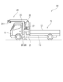
- FIG. 1 is a side view of a load-type truck crane according to an embodiment of the present invention.
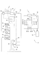
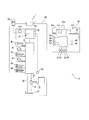
- FIG. 2 is a block diagram of a control system of the loadable truck crane.
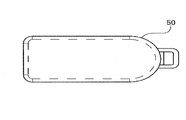
- FIG. 3 is a front view of the remote control terminal.
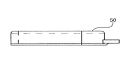
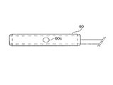
- FIG. 4A is a plan view of the wireless transmission unit.
- FIG. 4B is a side view of the wireless transmission unit.
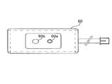
- FIG. 5A is a plan view of the receiving unit.
- FIG. 5B is a side view of the receiving unit.
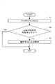
- FIG. 6 is a flowchart for explaining the flow of misplacement prevention control.
- FIG. 7 is a block diagram of a control system of the loadable truck crane according to the modification of the first embodiment.
- the remote control terminal misplacement prevention device, the remote control terminal, and the remote control terminal misplacement prevention system according to the present invention can be applied to a work vehicle such as a mobile crane, an aerial work vehicle, a wheel loader, or a hydraulic excavator.
- a work vehicle such as a mobile crane, an aerial work vehicle, a wheel loader, or a hydraulic excavator.
- mobile cranes include (in the narrow sense) truck cranes, (vehicles) loaded truck cranes, and wrecker truck cranes.
- Mobile cranes include (in a broad sense) truck cranes, (in a narrow sense) wheel cranes, and rough terrain cranes. Further, mobile cranes include (in a broad sense) wheel cranes, crawler cranes, railway cranes, and floating cranes.
- the present invention can be applied to such various mobile cranes.
- the remote operation terminal misplacement prevention device, the remote operation terminal, and the remote operation terminal misplacement prevention system according to the present invention can be applied to other work vehicles.
- the load-type truck crane CR includes a general-purpose truck 10 and a small crane 20.
- the small crane 20 is mounted on a vehicle frame 13 disposed between the cab 11 and the loading platform 12 of the general-purpose truck 10.
- the small crane 20 has a base 21, a post 22, and a boom 23.
- the base 21 is fixed on the vehicle frame 13.
- the post 22 is provided so as to be rotatable with respect to the base 21.
- the boom 23 is provided at the upper end of the post 22 so as to be raised and lowered.
- the post 22 has a built-in winch (not shown). A wire rope is led from the winch to the tip of the boom 23. This wire rope is wound around the hook 24 via a pulley at the tip of the boom 23.
- These posts 22, booms 23, and hooks 24 constitute a crane device.
- the small crane 20 includes outrigger devices 25 and 26 on both the left and right sides of the base 21.
- the crane device post 22, boom 23, and hook 24
- the outrigger devices 25 and 26 are collectively referred to as “work machine”.
- the small crane 20 has a lever group 27 for operating these work machines on both the left and right sides of the base 21.
- a crane device post 22, boom 23, and hook 24
- outrigger devices 25 and 26 have been described as examples of the work machine.
- the working machine is not limited to this.
- the working machine may be a working machine that is hydraulically driven via a PTO 30 described later.
- the configuration of the present embodiment can be applied to such various working machines.
- the hydraulic system of the small crane 20 mainly includes a hydraulic valve unit 31, a hydraulic pump 33, a main oil passage 34, a return oil passage 35, a plurality of hydraulic actuators 41 to 46, Have
- the hydraulic pump 33 supplies hydraulic oil from the tank 32 to the hydraulic valve unit 31.
- the main oil passage 34 connects the hydraulic pump 33 and the hydraulic valve unit 31.
- the return oil passage 35 connects the hydraulic valve unit 31 and the tank 32.
- the plurality of hydraulic actuators 41 to 46 are connected to the hydraulic valve unit 31.
- the hydraulic pump 33 is rotationally driven by taking out the rotational power of the engine via the PTO 30.
- the PTO 30 is connected to a PTO detector 36 that detects ON / OFF of the PTO 30.
- the PTO detector 36 may not be directly connected to the PTO 30.
- the PTO detector 36 may exist as a functional unit in the control device 70 and acquire ON / OFF instruction information of the PTO 30.
- the hydraulic valve unit 31 is connected to a boom expansion / contraction hydraulic cylinder 41, a winch hydraulic motor 42, a boom hoisting hydraulic cylinder 43, a swing hydraulic motor 44, and outrigger hydraulic cylinders 45 and 46 as hydraulic actuators. .
- a lever is attached to each switching control valve (not shown) constituting the hydraulic valve unit 31. By manually operating these levers, the direction and flow rate of the pressure oil supplied from the hydraulic pump 33 are switched.
- the levers attached to the switching control valve are arranged on the left and right sides of the base 21 as the lever group 27 (see FIG. 1).
- pilot cylinder is attached to each switching control valve separately from the lever.
- the direction and flow rate of the pressure oil supplied from the hydraulic pump 33 are also switched by such an operation of the pilot cylinder.
- a solenoid valve is attached to each pilot cylinder.
- the solenoid valve is connected to a control device 70 configured by a known computer or the like.
- the solenoid valve operates based on a control signal from the control device 70, thereby driving the pilot cylinder and switching the switching control valve. In this way, the control device 70 controls the operation of the work machine.
- Such a control device 70 is mounted on a substrate 70c such as a printed circuit board incorporated in the working machine.
- a work machine side communication unit 70 a that receives an operation signal from the remote operation terminal 80 is connected to the control device 70.
- Such a work machine side communication unit 70a may be mounted on the board 70c.
- the work machine side communication unit 70 a sends the operation signal received from the remote operation terminal 80 to the control device 70.
- the control device 70 controls the hydraulic valve unit 31 on the basis of the operation signal received from the work machine side communication unit 70a, so that the boom telescopic hydraulic cylinder 41, the winch hydraulic motor 42, the boom hoisting hydraulic cylinder 43, It controls the supply and discharge of pressure oil to the turning hydraulic motor 44 and the outrigger hydraulic cylinders 45 and 46.
- the boom 23, winch, post 22, and outrigger devices 25 and 26 are activated based on the operation signal from the remote operation terminal 80.
- the work implement can operate based on the operation instruction input from the lever group 27, or can operate based on the operation instruction input from the remote operation terminal 80.
- a receiving unit 60 that receives radio waves from a radio transmission unit 50 described later is connected to the control device 70 of the present embodiment.
- the function of the receiving unit 60 will be described later.
- the remote operation terminal 80 can be wirelessly or wiredly communicated bidirectionally with the work device control device 70 via the terminal-side communication unit 80a. Such a remote control terminal 80 can remotely control the work machine.
- the remote operation terminal 80 has a housing 92 and a grip portion 95. As shown in FIGS. 2 and 3, operation switches 81 to 90 such as various switches and levers and a display unit 91 which is a liquid crystal display are arranged on the upper portion of the remote operation terminal 80. The operation switches 81 to 90 are held by the housing 92.
- the operation switches 81 to 90 include a turning selection switch 81, an undulation selection switch 82, a winch selection switch 83, an expansion / contraction selection switch 84, a power switch 85, a horn switch 86, a navigation switch 87, a mode selection switch 88, A hook removal switch 89, a hook storage switch 90, and the like are included.
- Each of the switches 81 to 90 is a switch (also referred to as an operation input unit) for an operator to input an operation instruction (hereinafter referred to as “operation input”).
- operation input an operation instruction
- each of the switches 81 to 90 is connected to the control unit 80b.
- the controller 80b is mounted on a board 80c such as a printed board provided in the housing 92 of the remote operation terminal 80.
- the remote operation terminal 80 includes a terminal side communication unit 80a (also referred to as an operation signal transmission unit) connected to the work machine side communication unit 70a of the work machine so as to be capable of bidirectional wireless communication or wired communication.
- the terminal side communication unit 80a is connected to the control unit 80b. Note that the terminal-side communication unit 80a may be mounted on the board 80c.
- the operation input input from each of the switches 81 to 90 is sent to the control unit 80b.
- the control unit 80b generates an operation signal based on the operation input received from each of the switches 81 to 90. Then, the control unit 80b sends an operation signal to the terminal side communication unit 80a.
- the terminal-side communication unit 80a transmits the received operation signal to the work machine (specifically, the work machine-side communication unit 70a). In this way, the work machine is remotely operated by the remote operation terminal 80.
- the remote operation unit is configured by the switches 81 to 90 as the operation input unit, the control unit 80b, and the terminal side communication unit 80a as the operation signal transmission unit.
- a radio transmission unit 50 (also referred to as a transmission unit) that transmits (transmits) radio waves (radio signals) is connected to the remote operation terminal 80 of the present embodiment. That is, the wireless transmission unit 50 is fastened to the grip portion 95 of the remote operation terminal 80 by fastening means such as a belt so as not to be separated from the remote operation terminal 80 integrally. The function of the wireless transmission unit 50 will be described later.
- the remote operation terminal misplacement prevention system includes a work machine (post 22, boom 23, hook 24, and outrigger devices 25 and 26), a remote operation terminal 80, a radio transmission unit 50, a reception unit 60, and a PTO detector. 36, the determination part 61, the alerting
- the remote control terminal misplacement prevention device D includes at least a reception unit 60, a determination unit 61, and a notification unit 62. Further, the misplacement prevention device D for the remote operation terminal may include a work machine (post 22, boom 23, hook 24, and outrigger devices 25 and 26), a PTO detector 36, a notification stop means 60b, and the like.
- the work machine (post 22, boom 23, hook 24, and outrigger devices 25, 26) is driven by the power of the engine taken out through the PTO 30.
- the remote operation terminal 80 is for remotely operating the work implement (post 22, boom 23, hook 24, and outrigger devices 25, 26).
- the wireless transmission unit 50 (also referred to as a transmission device) is connected to the remote operation terminal 80 and transmits (transmits) radio waves (wireless signals).
- the frequency of the radio signal is different from the frequency of the operation signal sent from the terminal-side communication unit 80a to the work machine.
- the wireless signal is transmitted from the wireless transmission unit 50 to the reception unit 60 provided in the work machine by one-way communication. That is, the terminal side communication unit 80a and the receiving unit 60 are connected so as to be communicable by one-way communication.
- Such a configuration is effective for cost reduction because communication control can be simply configured.
- the wireless transmission unit 50 and the reception unit 60 may be connected so as to be able to communicate by bidirectional communication.
- the wireless transmission unit 50 is accommodated in a small case and is separate from the remote operation terminal 80. Are fastened to the remote control terminal 80 by fastening means such as a belt so as not to be separated from the remote control terminal 80.
- the wireless transmission unit 50 transmits a radio wave having a specific frequency at a predetermined radio wave intensity and at a predetermined time interval (for example, every 1.5 seconds) using a battery such as a lithium battery as a power source. Accordingly, the wireless transmission unit 50 transmits a wireless signal even when the power switch 85 of the remote operation terminal 80 is in the OFF state.
- the radio wave intensity of the radio wave transmitted by the wireless transmission unit 50 can be selected from a plurality of intensities (for example, five types of intensity) according to the environment in which it is used.
- the radio transmission unit 50 continuously transmits radio waves at predetermined time intervals, thereby notifying the reception unit 60 that receives the radio waves of the distance of the remote operation terminal 80.
- the receiving unit 60 (also referred to as a receiving device) receives radio waves transmitted from the wireless transmission unit 50. Such a receiving unit 60 is installed in any place of the work vehicle.
- the receiving unit 60 is accommodated in a small case, and the case is provided with an LED 60a and a notification stop means 60b on the front surface, and a side surface. Further, a pairing switch 60c for the wireless transmission unit 50 is disposed.
- the receiving unit 60 is provided in the loadable truck crane CR. Specifically, the receiving unit 60 is connected to the control device 70 inside the cab 11 of the loadable truck crane CR.
- the installation location of the receiving unit 60 is not limited to the cab 11 of the loadable truck crane CR, but may be on a rough terrain crane traveling body (also referred to as a vehicle).
- a rough terrain crane since the cab is at a high position, the storage location of the remote control terminal can be set at a low position.
- the receiving unit can be installed in or near the storage location of the remote control terminal.
- the LED 60a as a display means displays that the intensity of the radio wave is not more than a predetermined value, separately from the notification means 62. That is, the LED 60a lights up in green when the strength of the radio wave exceeds a predetermined value based on only the strength of the radio wave, regardless of whether the PTO 30 is on or off, and the strength of the radio wave becomes a predetermined value or less. If it is, it lights red.
- the operator can always check the LED 60a. Therefore, since the LED 60a is lit red before the PTO 30 is turned off, the operator can recognize that the remote operation terminal 80 is far and can confirm the position of the remote operation terminal 80. It becomes.
- the receiving unit 60 preferably has a pairing function for the wireless transmission unit 50, a battery warning function for the wireless transmission unit 50, and the like. In addition to this, it is also preferable to be able to confirm whether or not radio waves are transmitted from the wireless transmission unit 50 using a smartphone.
- the PTO detector 36 detects ON / OFF of the PTO 30.
- the PTO detector 36 sends the detection result to the determination unit 61.
- the determination unit 61 (also referred to as a control unit) is configured as a functional unit of the control device 70 and determines whether or not the remote operation terminal 80 is misplaced.
- the determination unit 61 receives the detection information detected by the PTO detector 36 and the radio wave intensity received by the receiving unit (not shown) of the receiving unit 60. Based on these two input values, the determination unit 61 determines that the remote operation terminal 80 is in the case where the PTO 30 is OFF and the radio wave intensity is equal to or less than a predetermined threshold (for example, ⁇ 95 dBm). Is determined to be misplaced.
- a predetermined threshold for example, ⁇ 95 dBm
- the determination unit 61 repeatedly performs the above determination at a predetermined time interval (for example, 1.5 seconds) while the PTO 30 is in the OFF state. Determination unit 61 may repeatedly perform the above determination at predetermined time intervals (for example, 1.5 seconds) even while the work vehicle is traveling.
- the predetermined threshold is, for example, a value related to the reception intensity with which it is possible to determine whether or not the remote operation terminal 80 exists in the cab 11 of the work machine.
- the predetermined threshold value is a value less than the minimum reception intensity among the reception intensity of the radio signal received by the reception unit 60 when the remote operation terminal 80 is present in the cab 11 of the work machine. is there.
- the minimum reception strength is ⁇ 90 dBm
- ⁇ 95 dBm is given as the predetermined threshold.
- the determination unit 61 has misplaced the remote operation terminal 80 (in other words, the cab 11). With such a predetermined threshold, it can be determined with high accuracy that the remote control terminal 80 is not present in the cab 11.
- Such a predetermined threshold value may be appropriately determined according to the width and shape of the cab 11.
- the predetermined threshold is, for example, outside the cab 11 of the work machine (the work machine with the door and window closed) and in the vicinity of the cab 11 (for example, a door). Or the reception intensity value of the radio signal received by the receiving unit 60 when the radio signal exists on the outer surface of the radio signal. With such a predetermined threshold, it can be determined with higher accuracy that the remote operation terminal 80 does not exist in the cab 11.
- the notification unit 62 notifies when the determination unit 61 determines that the remote operation terminal 80 is misplaced.
- the notification means 62 installed in the cab 11 receives a notification command from the determination unit 61 and notifies the operator that the remote operation terminal 80 has been forgotten.
- the notification means 62 includes a notification sound (voice or buzzer sound) and a notification display.
- a notification sound for example, a voice by a person such as “I forgot the remote operation terminal” or a buzzer sound such as “boo” is preferable.
- the notification display for example, it is preferable to display a message such as “Forgot the remote control terminal” in the monitor for the safety device, or to install a dedicated notification lamp (red lamp or the like).
- the notification stop unit 60b stops the notification by the notification unit 62. Specifically, the operator operates the notification stop unit 60b to cause the determination unit 61 to forcibly determine that the remote operation terminal 80 has not been left behind, and stop the notification by the notification unit 62. Alternatively, it is also preferable to directly issue a command to the notification unit 62 to stop the notification by operating the notification stop unit 60b.
- the ON / OFF of the PTO 30 is constantly monitored by the PTO detector 36, and when the switching of the PTO 30 to OFF is detected, detection information (OFF) is transmitted to the control device 70 (step S1). That is, misplacement prevention control is executed at the timing when the PTO 30 is turned off.
- radio waves transmitted from the wireless transmission unit 50 at predetermined time intervals are received by the reception unit 60.
- the determination unit 61 determines whether or not the radio wave intensity of the radio wave received by the receiving unit 60 is equal to or less than a predetermined value (step S2). If the radio wave intensity exceeds the predetermined value (NO in step S2), it is assumed that the remote operation terminal 80 has not been left behind, and the control is terminated.
- step S2 in FIG. 6 even when the radio field intensity exceeds a predetermined value, the determination unit 61 performs step S2 in FIG. 6 until a predetermined time elapses after the work vehicle starts traveling. It may be repeated. According to such a configuration, it is possible to reliably detect a situation in which the remote control terminal 80 is misplaced outside the cab 11 and in the vicinity of the cab 11.
- the determination unit 61 may continuously repeat step S2 of FIG. 6 while the work vehicle is traveling.
- step S2 of FIG. 6 if the intensity of the radio wave is equal to or lower than the predetermined value (YES in step S2), it is assumed that the remote operation terminal 80 has been misplaced and a notification command is issued to the notification means 62. That is, if the intensity of the radio wave is equal to or less than a predetermined value, it is considered that the remote operation terminal 80 is in a distant place, so that it has been misplaced.
- step S2 of FIG. 6 even when the radio field intensity is equal to or lower than the predetermined value, the determination unit 61 repeats step S2 of FIG. 6 until a predetermined time elapses after the work vehicle starts traveling. Also good. According to such a configuration, misplacement of the remote operation terminal 80 can be detected more reliably.
- the notification unit 62 notifies the operator (step S3). For example, an announcement “A remote control terminal has been misplaced. Please be careful.” Is broadcast from a speaker arranged in the cab 11. In this way, misplacement prevention control is executed.
- misplacement of the remote operation terminal 80 can be prevented. Furthermore, according to the remote operation terminal misplacement prevention system and misplacement prevention apparatus D according to the present embodiment, misplacement of the remote operation terminal 80 can be prevented even when the installation position of the remote operation terminal 80 is not limited in the vehicle.
- the remote operation terminal misplacement prevention system and the remote operation terminal misplacement prevention device D prevent the remote operation terminal 80 from being misplaced at the work site or in the office or home. it can. As a result, the burden on the user due to the loss / re-purchase of the remote operation terminal 80 can be reduced. Furthermore, if the remote operation terminal 80 is not misplaced, the work efficiency at the site is not impaired. In addition, the degree of freedom of arrangement increases due to the wireless connection, and the number of mounting steps can be reduced.
- the receiving unit 60 can be installed in the cab 11 of the loadable truck crane CR. With this configuration, when the PTO 30 is turned off in the cab 11, it can be recognized that the remote operation terminal 80 has been left behind. This also applies to truck cranes that do not have a loading platform. Of course, for other mobile cranes, the receiving unit 60 can be installed in the cab.
- the receiving unit can be installed on the traveling body of the rough terrain crane.
- the notification means 62 is preferably arranged in the cab 11.
- the receiving unit 60 further includes notification stop means 60b for stopping notification by the notification means 62. If comprised in this way, when remote control terminal 80 is lost, it can prevent continuing alerting
- the receiving unit 60 further includes an LED 60a as a display unit that displays that the intensity of the radio wave is equal to or lower than a predetermined value, separately from the notification unit 62. Then, the operator can always check the LED 60a. Therefore, since the LED 60a is lit red before the PTO 30 is turned off, the operator can recognize that the remote operation terminal 80 is far and can confirm the position of the remote operation terminal 80. It becomes.
- the determination unit 61 and the notification unit 62 are described as different configurations from the reception unit 60, but the present invention is not limited to this, and the determination unit 61 and the notification unit 62 are integrated with the reception unit 60. It can also be configured.
- FIG. 7 shows an example of a modification of the present embodiment.
- the receiving unit 60A is mounted as a wireless module on a board 70c incorporated in the work machine.
- a control device 70 of the work machine is also mounted on the board 70c.
- Such a receiving unit 60 ⁇ / b> A is connected to the control device 70.
- the wireless transmission unit 50a is incorporated in the remote operation terminal 80 as a wireless module.
- the wireless transmission unit 50a is accommodated in the housing 92 (see FIG. 3).
- Such a radio transmission unit 50 a is mounted on a substrate 80 c on which a control unit 80 b of the remote control terminal 80 and the like are mounted in the housing 92.
- the power source of the wireless transmission unit 50a may be a power source 80d (secondary battery or the like) common to the remote operation terminal 80 (specifically, the remote operation unit).
- the wireless transmission unit 50a transmits a wireless signal.
- the frequency of the radio signal transmitted from the radio transmission unit 50a is different from the frequency of the operation signal sent from the terminal side communication unit 80a to the work machine.
- the wireless transmission unit 50a transmits a wireless signal when the power switch 85 of the remote operation terminal 80 is in the OFF state, and the power switch 85 of the remote operation terminal 80 is in the ON state. In this case, no radio signal is transmitted. Note that the wireless transmission unit 50a may always transmit a wireless signal at a predetermined time interval regardless of the state of the power switch 85 of the remote operation terminal 80.
- the wireless transmission unit 50 has been described as another configuration retrofitted to the remote operation terminal 80.
- the present invention is not limited to this, and the wireless transmission unit 50 is not limited to this. 50 may be configured (built-in) integrally with the remote control terminal 80.
- the receiving unit 60 has been described as another configuration that is connected to the control device 70 by wire.
- the present invention is not limited to this, and the receiving unit 60 is not externally attached. It can also be constructed in one piece.
- the remote operation terminal misplacement prevention device includes a work machine driven by taking out the power of the engine via the PTO, and a remote operation for remotely operating the work machine.
- a terminal a wireless transmission unit connected to the remote control terminal for transmitting radio waves, a reception unit for receiving the radio waves, which is installed at any location of the work vehicle, and the PTO is turned on
- the remote control terminal is misplaced when the PTO detector for detecting / OFF and the PTO are OFF and the intensity of the radio wave received by the receiving unit is below a predetermined value.
- a determination unit that determines that the remote control terminal is misplaced, and a notification unit that notifies when it is determined that the remote control terminal is misplaced.
- the work vehicle is a loaded truck crane.
- the receiving unit is installed in the cab of the loading truck crane.
- the work vehicle may be a rough terrain crane.
- the receiving unit is installed on the traveling body of the rough terrain crane.
- the receiving unit may further include notification stop means for stopping notification by the notification means.
- the receiving unit further includes display means for displaying that the intensity of the radio wave is not more than the predetermined value, separately from the notifying means. May be.
- CR loading type truck crane D misplacement prevention device 10 general purpose truck 11 cab 12 loading platform 13 vehicle frame 20 small crane 21 base 22 post (work machine) 23 Boom (work machine) 24 hook (work machine) 25, 26 Outrigger device (work machine) 27 Lever group 30 PTO 31 Hydraulic valve unit 32 Tank 33 Hydraulic pump 34 Main oil path 35 Return oil path 36 PTO detector 41 Hydraulic cylinder for boom expansion and contraction (hydraulic actuator) 42 Hydraulic motor for winch (hydraulic actuator) 43 Boom hoisting hydraulic cylinder (hydraulic actuator) 44 Hydraulic motor for turning (hydraulic actuator) 45, 46 Outrigger hydraulic cylinder (hydraulic actuator) 50 wireless transmission unit 50a wireless transmission unit 60, 60A reception unit 60a LED (display means) 60b Notification stop unit 60c Pairing switch 61 Judgment unit 62 Notification unit 70 Control device 70a Work machine side communication unit 70c Substrate 80 Remote operation terminal 80a Terminal side communication unit 80b Control unit 80c Substrate 80d Power supply 81 Swivel
Abstract
車両に搭載されPTO装置を介して駆動される作業機を、遠隔操作する遠隔操作端末の置き忘れ防止装置を、車両に設けられ、遠隔操作端末に設けられた発信デバイスが発信する無線信号を受信する受信デバイスと、PTO装置がOFF状態である場合に、受信デバイスが発信デバイスから受信した無線信号の受信強度が、所定の閾値以下であるか否かの判定を行う判定部と、受信強度が所定の閾値以下の場合に報知する報知部と、を有するように構成する。
Description
本発明は、移動式クレーンなどの作業車両に用いられる遠隔操作端末の置き忘れ防止装置、遠隔操作端末、および遠隔操作端末の置き忘れ防止システムに関するものである。
近年、移動式クレーンを含む作業車両を遠隔操作端末によって遠隔操作することが多くなってきている。この遠隔操作端末は、作業車両から離れた位置において、オペレータにより使用される。このため、遠隔操作端末は、作業終了後に作業現場に置き忘れられることがある。このような遠隔操作端末の置き忘れを防止するために、置き忘れ警報システムが実現されている。
例えば、特許文献1に記載された軌陸車の遠隔操作装置の置き忘れ警報システムは、軌道走行可能な状態において遠隔操作装置が格納部に格納されていない場合に警告するように構成されている。このような構成によれば、軌道走行時の遠隔操作装置の置き忘れを防止することができる。
しかしながら、特許文献1の置き忘れ警報システムは、軌陸車内に特別に準備された位置に格納部を設置し、この格納部に遠隔操作装置を格納する必要があった。そのため、遠隔操作端末の格納部の設置場所が限定されていないような作業車両(積載形トラッククレーンを含む)には適用することができなかった。
本発明は、作業車両における遠隔操作端末の格納場所が限定されることのない遠隔操作端末の置き忘れ防止装置、遠隔操作端末、および遠隔操作端末の置き忘れ防止システムを提供することを目的としている。
本発明に係る遠隔操作端末の置き忘れ防止装置は、車両に搭載されPTO装置を介して駆動される作業機を、遠隔操作する遠隔操作端末の置き忘れ防止装置であって、車両に設けられ、遠隔操作端末に設けられた発信デバイスが発信する無線信号を受信する受信デバイスと、PTO装置がOFF状態である場合に、受信デバイスが発信デバイスから受信した無線信号の受信強度が、所定の閾値以下であるか否かの判定を行う判定部と、受信強度が所定の閾値以下の場合に報知する報知部と、を有する。
また、本発明に係る遠隔操作端末は、車両に搭載されPTO装置を介して駆動される作業機を遠隔操作するための遠隔操作端末であって、作業機への操作指示を入力するための操作入力部、操作入力部から入力された操作指示に基づいて操作信号を生成する制御部、および操作信号を作業機に送信する操作信号送信部、を有する遠隔操作部と、操作信号とは異なる周波数の無線信号を発信する発信部と、を備える。
また、本発明に係る遠隔操作端末の置き忘れ防止システムは、車両に搭載されPTO装置を介して駆動される作業機を遠隔操作する遠隔操作端末と、遠隔操作端末に設けられた発信デバイスと、車両に設けられ、発信デバイスが発信する無線信号を受信する受信デバイスと、PTO装置がOFF状態である場合に、受信デバイスが発信デバイスから受信した無線信号の受信強度が、所定の閾値以下であるか否かの判定を行う判定部と、受信強度が所定の閾値以下の場合に報知する報知部と、を備える。
本発明によれば、作業車両における遠隔操作端末の格納場所が限定されることのない遠隔操作端末の置き忘れ防止装置、遠隔操作端末、および遠隔操作端末の置き忘れ防止システムを提供できる。
以下、本発明の実施形態について図面を参照して説明する。本発明に係る遠隔操作端末の置き忘れ防止装置、遠隔操作端末、および遠隔操作端末の置き忘れ防止システムは、移動式クレーン、高所作業車、ホイルローダー、または油圧ショベル等の作業車両に適用できる。
移動式クレーンとしては、(狭義の)トラッククレーン、(車両)積載形トラッククレーン、及びレッカー形トラッククレーンを含む。また、移動式クレーンとしては、(広義の)トラッククレーン、(狭義の)ホイールクレーン、及びラフテレーンクレーンを含む。さらに、移動式クレーンとしては、(広義の)ホイールクレーン、クローラクレーン、鉄道クレーン、および浮クレーンなどを含む。本発明は、このような種々の移動式クレーンに適用できる。以下、積載形トラッククレーンを例に挙げて説明するが、他の作業車両にも本発明に係る遠隔操作端末の置き忘れ防止装置、遠隔操作端末、および遠隔操作端末の置き忘れ防止システムを適用できる。
[実施形態]
以下、図1~7を参照して、本発明の実施形態に係る遠隔操作端末の置き忘れ防止装置、遠隔操作端末、および遠隔操作端末の置き忘れ防止システムについて説明する。
以下、図1~7を参照して、本発明の実施形態に係る遠隔操作端末の置き忘れ防止装置、遠隔操作端末、および遠隔操作端末の置き忘れ防止システムについて説明する。
[積載形トラッククレーンの全体構成]
まず、積載形トラッククレーンCRの構成について説明する。図1に示されるように、積載形トラッククレーンCRは、汎用トラック10と、小型クレーン20と、を有する。
まず、積載形トラッククレーンCRの構成について説明する。図1に示されるように、積載形トラッククレーンCRは、汎用トラック10と、小型クレーン20と、を有する。
小型クレーン20は、汎用トラック10の運転室11と荷台12との間に配置された車両フレーム13に搭載されている。
小型クレーン20は、ベース21と、ポスト22と、ブーム23と、を有する。
ベース21は、車両フレーム13上に固定されている。ポスト22は、ベース21に対して旋回可能に設けられている。ブーム23は、ポスト22の上端部に起伏可能に設けられている。
ポスト22にはウインチ(不図示)が内蔵されている。ウインチからブーム23の先端部までワイヤロープが導かれている。このワイヤロープは、ブーム23の先端部の滑車を介してフック24に掛け回されている。これらのポスト22、ブーム23、およびフック24によりクレーン装置が構成されている。
さらに、小型クレーン20は、ベース21の左右両側にアウトリガ装置25、26を備えている。以下では、クレーン装置(ポスト22、ブーム23、およびフック24)とアウトリガ装置25、26とをまとめて「作業機」と称する。
そして、小型クレーン20は、ベース21の左右両側に、これらの作業機を操作するためのレバー群27を有する。なお、ここでは、作業機としてクレーン装置(ポスト22、ブーム23、およびフック24)とアウトリガ装置25、26とを例に挙げて説明した。ただし、作業機は、これに限定されるものではない。たとえば、作業機として、後述のPTO30を介して油圧駆動される作業用の機械などが挙げられる。このような種々の作業機に対して、本実施形態の構成は適用可能である。
[油圧系・制御系の構成]
図2に示すように、小型クレーン20の油圧系は、主に、油圧バルブユニット31と、油圧ポンプ33と、主油路34と、戻油路35と、複数の油圧アクチュエータ41~46と、を有する。
図2に示すように、小型クレーン20の油圧系は、主に、油圧バルブユニット31と、油圧ポンプ33と、主油路34と、戻油路35と、複数の油圧アクチュエータ41~46と、を有する。
油圧ポンプ33は、油圧バルブユニット31にタンク32内から作動油を供給する。主油路34は、油圧ポンプ33と油圧バルブユニット31とを接続している。戻油路35は、油圧バルブユニット31とタンク32とを接続している。複数の油圧アクチュエータ41~46は、油圧バルブユニット31に接続されている。
このうち油圧ポンプ33は、PTO30を介してエンジンの回転動力を取り出すことによって回転駆動される。そして、本実施形態では、PTO30にはPTO30のON/OFFを検出するPTO検出器36が接続されている。
なお、PTO検出器36は、PTO30に直接に接続されるものでなくてもよい。PTO検出器36は、制御装置70内に機能部として存在して、PTO30のON/OFFの指示情報を取得するものであってもよい。
油圧バルブユニット31には、油圧アクチュエータとして、ブーム伸縮用油圧シリンダ41、ウインチ用油圧モータ42、ブーム起伏用油圧シリンダ43、旋回用油圧モータ44、およびアウトリガ用油圧シリンダ45、46が接続されている。
油圧バルブユニット31を構成する各切換制御弁(不図示)には、それぞれレバーが取り付けられている。これら各レバーを手動操作することによって、油圧ポンプ33から供給される圧油の方向および流量が切り換えられる。切換制御弁に取り付けられたレバーは、レバー群27としてベース21の左右両側に配置されている(図1参照)。
さらに、切換制御弁には、レバーとは別にそれぞれパイロットシリンダが取り付けられている。このようなパイロットシリンダの動作によっても、油圧ポンプ33から供給される圧油の方向および流量が切り換えられる。
各パイロットシリンダには、電磁弁が付設されている。電磁弁は、公知のコンピュータ等で構成された制御装置70に接続されている。電磁弁は、制御装置70からの制御信号に基づいて動作することで、パイロットシリンダを駆動し、切換制御弁を切り換える。このようにして、制御装置70は作業機の動作を制御する。
このような制御装置70は、作業機に組み込まれたプリント基板などの基板70cに実装されている。制御装置70には、遠隔操作端末80からの操作信号を受信する作業機側通信部70aが接続されている。このような作業機側通信部70aは、基板70cに実装されていてもよい。作業機側通信部70aは、遠隔操作端末80から受信した操作信号を、制御装置70に送る。
制御装置70は、作業機側通信部70aから受け取った操作信号に基づいて、油圧バルブユニット31を制御することにより、ブーム伸縮用油圧シリンダ41、ウインチ用油圧モータ42、ブーム起伏用油圧シリンダ43、旋回用油圧モータ44、およびアウトリガ用油圧シリンダ45、46への圧油の給排を制御する。この結果、遠隔操作端末80からの操作信号に基づいて、ブーム23、ウインチ、ポスト22、およびアウトリガ装置25、26が作動する。以上のように、作業機は、レバー群27から入力された操作指示に基づいて動作することもできるし、遠隔操作端末80から入力された操作指示に基づいて、動作することもできる。
さらに、本実施形態の制御装置70には、後述する無線発信ユニット50からの電波を受信する受信ユニット60が接続されている。受信ユニット60の機能については後述する。
[遠隔操作端末]
遠隔操作端末80は、端末側通信部80aを介して、作業機の制御装置70と双方向に無線通信又は有線通信可能となっている。このような遠隔操作端末80は、作業機を遠隔操作できる。
遠隔操作端末80は、端末側通信部80aを介して、作業機の制御装置70と双方向に無線通信又は有線通信可能となっている。このような遠隔操作端末80は、作業機を遠隔操作できる。
遠隔操作端末80は、ハウジング92と、把持部95と、を有する。図2および図3に示すように、遠隔操作端末80の上部には、各種のスイッチやレバー等の操作用スイッチ81~90と、液晶ディスプレイである表示部91と、が配置されている。操作用スイッチ81~90は、ハウジング92に保持されている。
操作用スイッチ81~90は、具体的には、旋回選択スイッチ81、起伏選択スイッチ82、ウインチ選択スイッチ83、伸縮選択スイッチ84、電源スイッチ85、ホーンスイッチ86、ナビスイッチ87、モード選択スイッチ88、フック取出スイッチ89、およびフック格納スイッチ90などを含む。
上述の各スイッチ81~90は、作業者が操作指示を入力(以下、「操作入力」という。)するためのスイッチ(操作入力部ともいう。)である。また、各スイッチ81~90はそれぞれ、制御部80bに接続されている。制御部80bは、遠隔操作端末80のハウジング92内に設けられたプリント基板などの基板80cに実装されている。
また、遠隔操作端末80は、作業機の作業機側通信部70aに双方向の無線通信又は有線通信可能に接続される端末側通信部80a(操作信号送信部ともいう。)を有する。端末側通信部80aは、制御部80bに接続されている。なお、端末側通信部80aは、基板80cに実装されていてもよい。
各スイッチ81~90から入力された操作入力は、制御部80bに送られる。制御部80bは、各スイッチ81~90から受け取った操作入力に基づいて、操作信号を生成する。そして、制御部80bは、操作信号を、端末側通信部80aに送る。端末側通信部80aは、受け取った操作信号を、作業機(具体的には、作業機側通信部70a)に送信する。このようにして作業機は、遠隔操作端末80により、遠隔操作される。なお、操作入力部である各スイッチ81~90、制御部80b、および操作信号送信部である端末側通信部80aにより、遠隔操作部が構成されている。
さらに、本実施形態の遠隔操作端末80には、電波(無線信号)を発信(送信)する無線発信ユニット50(発信部ともいう。)が繋がれている。すなわち、無線発信ユニット50は、遠隔操作端末80と一体になって離れないように、ベルトなどの締結手段によって遠隔操作端末80の把持部95と締結されている。無線発信ユニット50の機能については後述する。
[置き忘れ防止システム]
遠隔操作端末の置き忘れ防止システムは、作業機(ポスト22、ブーム23、フック24、およびアウトリガ装置25、26)と、遠隔操作端末80と、無線発信ユニット50と、受信ユニット60と、PTO検出器36と、判断部61と、報知手段62と、報知停止手段60b(図5A参照)と、を有する。
遠隔操作端末の置き忘れ防止システムは、作業機(ポスト22、ブーム23、フック24、およびアウトリガ装置25、26)と、遠隔操作端末80と、無線発信ユニット50と、受信ユニット60と、PTO検出器36と、判断部61と、報知手段62と、報知停止手段60b(図5A参照)と、を有する。
なお、遠隔操作端末の置き忘れ防止装置Dは、少なくとも、受信ユニット60、判断部61、および報知部62を含んで構成される。また、遠隔操作端末の置き忘れ防止装置Dは、作業機(ポスト22、ブーム23、フック24、およびアウトリガ装置25、26)、PTO検出器36、および報知停止手段60bなどを含んでもよい。
作業機(ポスト22、ブーム23、フック24、およびアウトリガ装置25、26)は、PTO30を介して取り出されたエンジンの動力により駆動される。
[遠隔操作端末]
遠隔操作端末80は、作業機(ポスト22、ブーム23、フック24、およびアウトリガ装置25、26)を遠隔操作するためのものである。
遠隔操作端末80は、作業機(ポスト22、ブーム23、フック24、およびアウトリガ装置25、26)を遠隔操作するためのものである。
[無線発信ユニット]
無線発信ユニット50(発信デバイスともいう。)は、遠隔操作端末80に接続されて電波(無線信号)を発信(送信)する。上記無線信号の周波数は、端末側通信部80aが作業機に送る操作信号の周波数とは異なる。また、上記無線信号は、無線発信ユニット50から作業機に設けられた受信ユニット60への一方向通信により送信される。つまり、端末側通信部80aと受信ユニット60とは、一方向通信により通信可能に接続される。このような構成は、通信制御をシンプルに構成できるため、低コスト化に効果的である。ただし、無線発信ユニット50と受信ユニット60とは、双方向通信による通信可能に接続されてもよい。
無線発信ユニット50(発信デバイスともいう。)は、遠隔操作端末80に接続されて電波(無線信号)を発信(送信)する。上記無線信号の周波数は、端末側通信部80aが作業機に送る操作信号の周波数とは異なる。また、上記無線信号は、無線発信ユニット50から作業機に設けられた受信ユニット60への一方向通信により送信される。つまり、端末側通信部80aと受信ユニット60とは、一方向通信により通信可能に接続される。このような構成は、通信制御をシンプルに構成できるため、低コスト化に効果的である。ただし、無線発信ユニット50と受信ユニット60とは、双方向通信による通信可能に接続されてもよい。
無線発信ユニット50は、図3、図4A、および図4Bに示すように、小型のケース内に収容されるものであり、遠隔操作端末80と別体ではあるが、このような無線発信ユニット50は、遠隔操作端末80と一体になって離れないように、ベルトなどの締結手段によって遠隔操作端末80と締結されている。無線発信ユニット50は、リチウム電池等の電池を電源として、所定の電波強度かつ所定の時間間隔(例えば1.5秒毎)で特定の周波数の電波を発信する。したがって、無線発信ユニット50は、遠隔操作端末80の電源スイッチ85がOFF状態の場合でも、無線信号を発信する。
ここにおいて、無線発信ユニット50が発信する電波の電波強度は、使用される環境に応じて複数の強度(例えば5種類の強度)の中から選択できるように構成することが好ましい。このように、無線発信ユニット50は所定の時間間隔で断続的に電波を発信しつづけることによって、この電波を受信する受信ユニット60に対して遠隔操作端末80の遠近を知らせるようになっている。
[受信ユニット]
受信ユニット60(受信デバイスともいう。)は、無線発信ユニット50が発信する電波を受信する。このような受信ユニット60は、作業車のいずれかの場所に設置されている。
受信ユニット60(受信デバイスともいう。)は、無線発信ユニット50が発信する電波を受信する。このような受信ユニット60は、作業車のいずれかの場所に設置されている。
具体的には、受信ユニット60は、図5Aおよび図5Bに示すように、小型のケース内に収容されるものであり、このケースには、正面にLED60aと報知停止手段60bが配置され、側面に無線発信ユニット50に対するペアリングスイッチ60cが配置されている。受信ユニット60は、積載形トラッククレーンCRに設けられている。具体的には、受信ユニット60は、積載型トラッククレーンCRの運転室11の内部において制御装置70に接続されている。
なお、受信ユニット60の設置場所は、積載形トラッククレーンCRの運転室11内に限定されるものではなく、ラフテレーンクレーンの走行体(車両ともいう。)上などであってもよい。ラフテレーンクレーンの場合には、運転室が高い位置にあるため、遠隔操作端末の格納場所を低い位置に設定することができる。この場合には、受信ユニットを、遠隔操作端末の格納場所内や格納場所の近くに設置することができる。
表示手段としてのLED60aは、報知手段62とは別に、電波の強度が所定値以下となっていることを表示する。すなわち、LED60aは、PTO30のON/OFFによらず、電波の強度のみに基づいて、電波の強度が所定値を超えている場合には緑色を点灯し、電波の強度が所定値以下となっている場合には赤色を点灯する。
このような表示手段を備えることで、オペレータはLED60aを常に確認することができる。したがって、PTO30をOFFにするよりも前にLED60aが赤色を点灯していることで、オペレータは遠隔操作端末80が遠くにあることを認識して、遠隔操作端末80の位置を確認することが可能となる。
さらに、受信ユニット60は、無線発信ユニット50に対するペアリング機能、無線発信ユニット50のバッテリー警告機能などを備えることが好ましい。この他にも、スマートフォンを使用して無線発信ユニット50から電波が送信されているか否かを確認できるようにすることなども好ましい。
[PTO検出器]
PTO検出器36は、PTO30のON/OFFを検出する。PTO検出器36は、検出結果を判断部61に送る。
PTO検出器36は、PTO30のON/OFFを検出する。PTO検出器36は、検出結果を判断部61に送る。
[判断部]
判断部61(制御部ともいう。)は、制御装置70の機能部として構成されるものであり、遠隔操作端末80が置き忘れられているか否かを判断する。判断部61には、PTO検出器36によって検出された検出情報と、受信ユニット60の受信部(不図示)で受信された電波強度とが入力される。そして、判断部61は、これら2つの入力値に基づいて、PTO30がOFFになっており、かつ、電波強度が所定の閾値(例えば、-95dBm)以下になっている場合に、遠隔操作端末80が置き忘れられていると判断する。判断部61は、遠隔操作端末80が置き忘れられていると判断した場合に、報知手段62に報知命令を出す。
判断部61(制御部ともいう。)は、制御装置70の機能部として構成されるものであり、遠隔操作端末80が置き忘れられているか否かを判断する。判断部61には、PTO検出器36によって検出された検出情報と、受信ユニット60の受信部(不図示)で受信された電波強度とが入力される。そして、判断部61は、これら2つの入力値に基づいて、PTO30がOFFになっており、かつ、電波強度が所定の閾値(例えば、-95dBm)以下になっている場合に、遠隔操作端末80が置き忘れられていると判断する。判断部61は、遠隔操作端末80が置き忘れられていると判断した場合に、報知手段62に報知命令を出す。
判断部61は、PTO30がOFF状態である間、所定の時間間隔(たとえば、1.5秒)で上述の判定を繰り返し行う。判断部61は、作業車両の走行中も、所定の時間間隔(たとえば、1.5秒)で上述の判定を繰り返し行ってもよい。
所定の閾値は、たとえば、遠隔操作端末80が作業機の運転室11内に存在するか否かを判定可能な受信強度に関する値である。具体的には、所定の閾値は、遠隔操作端末80が作業機の運転室11内に存在する場合に、受信ユニット60が受信する上記無線信号の受信強度のうち最小の受信強度未満の値である。一例として、上記最小の受信強度が-90dbmである場合には、所定の閾値として、-95dbmが挙げられる。この場合、判断部61は、PTO30がOFFになっており、かつ、受信ユニット60が受信した電波強度が-95dbm以下の場合に、遠隔操作端末80が置き忘れられている(換言すれば、運転室11内に存在していない)と判断する。このような所定の閾値であれば、遠隔操作端末80が運転室11内に存在していないことを高い精度で判定できる。このような所定の閾値は、運転室11の広さ、形に応じて適宜決定されてよい。
また、所定の閾値は、たとえば、遠隔操作端末80が作業機(ドアおよび窓が閉じている状態の作業機)の運転室11の外であって、かつ、運転室11の近傍(たとえば、ドアの外側面)に存在する場合に、受信ユニット60が受信する上記無線信号の受信強度の値であってもよい。このような所定の閾値であれば、遠隔操作端末80が、運転室11内に存在していないことを、より高い精度で判定できる。
[報知手段]
報知手段62は、判断部61が、遠隔操作端末80が置き忘れられていると判断したときに報知する。
報知手段62は、判断部61が、遠隔操作端末80が置き忘れられていると判断したときに報知する。
運転室11内に設置される報知手段62は、判断部61からの報知命令を受けて、オペレータに遠隔操作端末80が忘れられていることを報知する。報知手段62は、報知音(音声又はブザー音)、報知表示を含む。報知音としては、例えば、「遠隔操作端末を忘れています」といった人による音声や、「ブー」といったブザー音などが好ましい。報知表示としては、例えば、安全装置用のモニタ内の「遠隔操作端末を忘れています。」といったメッセージの表示や、専用の報知灯(赤色ランプなど)を搭載することなどが好ましい。
[報知停止手段]
報知停止手段60bは、報知手段62による報知を停止させる。具体的には、オペレータは、報知停止手段60bを操作することで、遠隔操作端末80を置き忘れていないことを判断部61に強制的に判断させて、報知手段62による報知を停止させる。あるいは、報知停止手段60bを操作することで、直接に報知手段62に命令を出して報知を停止させることも好ましい。
報知停止手段60bは、報知手段62による報知を停止させる。具体的には、オペレータは、報知停止手段60bを操作することで、遠隔操作端末80を置き忘れていないことを判断部61に強制的に判断させて、報知手段62による報知を停止させる。あるいは、報知停止手段60bを操作することで、直接に報知手段62に命令を出して報知を停止させることも好ましい。
[作用・効果について]
次に、図6のフローチャートを用いて、本実施例の遠隔操作端末の置き忘れ防止システムおよび置き忘れ防止装置Dによる置き忘れ防止制御の流れについて説明する。
次に、図6のフローチャートを用いて、本実施例の遠隔操作端末の置き忘れ防止システムおよび置き忘れ防止装置Dによる置き忘れ防止制御の流れについて説明する。
PTO検出器36によって、PTO30のON/OFFが常に監視されており、PTO30のOFFへの切り換えが検出されると、検出情報(OFF)が制御装置70に伝送される(ステップS1)。すなわち、PTO30がOFFにされたタイミングで、置き忘れ防止制御が実行される。
次に、無線発信ユニット50から所定の時間間隔で発信された電波が、受信ユニット60で受信される。そして、判断部61は、受信ユニット60で受信された電波の電波強度が所定値以下か否かを判定する(ステップS2)。電波強度が所定値を超えていれば(ステップS2のNO)、遠隔操作端末80を置き忘れていないものとみなして制御を終了する。
なお、図6のステップS2において、電波強度が所定値を超えている場合でも、判断部61は、作業車両が走行を開始してから所定時間が経過するまでの間、図6のステップS2を繰り返してもよい。このような構成によれば、遠隔操作端末80を運転室11の外かつ運転室11の近傍に置き忘れているような状況を、確実に検知できる。
また、図6のステップS2において、電波強度が所定値を超えている場合でも、判断部61は、作業車両の走行中、継続的に図6のステップS2を繰り返してもよい。
図6のステップS2において、電波の強度が所定値以下であれば(ステップS2のYES)、遠隔操作端末80を置き忘れているとみなして、報知手段62に報知命令を出す。つまり、電波の強度が所定値以下となっていれば、遠隔操作端末80が遠い場所にあると考えられるため、置き忘れたものとみなしている。なお、図6のステップS2において、電波強度が所定値以下の場合でも、判断部61は、作業車両が走行を開始してから所定時間が経過するまでの間、図6のステップS2を繰り返してもよい。このような構成によれば、遠隔操作端末80の置き忘れを、より確実に検知できる。
そして、判断部61によって遠隔操作端末80が置き忘れられていると判断されて、報知命令を受けると、報知手段62はオペレータに報知する(ステップS3)。例えば、運転室11内に配置されたスピーカから「遠隔操作端末を置き忘れています。ご注意ください。」というアナウンスが放送される。このようにして、置き忘れ防止制御が実行される。
[作用・効果]
次に、本実施形態に係る遠隔操作端末の置き忘れ防止システムおよび置き忘れ防止装置Dの奏する効果を列挙して説明する。
次に、本実施形態に係る遠隔操作端末の置き忘れ防止システムおよび置き忘れ防止装置Dの奏する効果を列挙して説明する。
(1)上述してきたように、本実施形態に係る遠隔操作端末の置き忘れ防止装置Dによれば、遠隔操作端末80の置き忘れを防止できる。さらに、本実施形態に係る遠隔操作端末の置き忘れ防止システムおよび置き忘れ防止装置Dによれば、車両において遠隔操作端末80の設置位置が限定されていない場合でも遠隔操作端末80の置き忘れを防止できる。
つまり、本実施形態に係る遠隔操作端末の置き忘れ防止システムおよび遠隔操作端末の置き忘れ防止装置Dを備えることで、遠隔操作端末80を作業現場へ置き忘れたり、事務所や自宅に置き忘れたりすることを防止できる。これによって、遠隔操作端末80の紛失・再購入によるユーザ負担を軽減することができる。さらに、遠隔操作端末80を置き忘れることがなければ、現場の作業効率を損なうことがない。加えて、無線化によって配置の自由度が増すうえ、取付工数の低減にもなる。
(2)また、作業車が積載形トラッククレーンCR等の場合には、受信ユニット60は、積載形トラッククレーンCRの運転室11内に設置されることが可能である。このように構成すれば、運転室11内でPTO30をOFFにしたときに、遠隔操作端末80を置き忘れていることを認識することができる。この点については、荷台を備えないトラッククレーンでも同様である。なお、その他の移動式クレーンについても、もちろん運転室内に受信ユニット60を設置することが可能である。
(3)あるいは、作業車がラフテレーンクレーン(又はオールテレーンクレーン)等の場合には、受信ユニットは、ラフテレーンクレーンの走行体上に設置されることが可能である。なお、この場合でも、報知手段62は、運転室11内に配置されることが好ましい。このように構成すれば、運転室11内でPTO30をOFFにしたときに、遠隔操作端末80を置き忘れていることを認識することができる。特に、大型の移動式クレーンのジブの取付/取外作業を遠隔操作で行う場合などに、遠隔操作端末80を置くために運転室まで昇る必要がなくなるため都合が良い。なお、その他の移動式クレーンについても、もちろん走行体上に受信ユニット60を設置することが可能である。
(4)また、受信ユニット60は、報知手段62による報知を停止させる報知停止手段60bをさらに有している。このように構成すれば、遠隔操作端末80を紛失した場合に、報知され続けることを防止できる。つまり、遠隔操作端末80を置き忘れた場合には、PTO30をOFFにしたときにしばらくの間だけ報知してオペレータに気付かせればよく、その後は報知を停止させることができる。
(5)さらに、受信ユニット60は、報知手段62とは別に、電波の強度が所定値以下となっていることを表示する表示手段としてのLED60aをさらに備えている。そうすると、オペレータはLED60aを常に確認することができる。したがって、PTO30をOFFにするよりも前にLED60aが赤色を点灯していることで、オペレータは遠隔操作端末80が遠くにあることを認識して、遠隔操作端末80の位置を確認することが可能となる。
以上、図面を参照して、本実施形態を詳述してきたが、具体的な構成は、この実施形態に限らず、本発明の要旨を逸脱しない程度の設計的変更は、本発明に含まれる。
例えば、本実施形態では、判断部61及び報知手段62を受信ユニット60とは別の構成として説明したが、これに限定されるものではなく、判断部61及び報知手段62を受信ユニット60と一体に構成することもできる。
図7は、本実施形態の変形例の一例を示している。本変形例の場合、受信ユニット60Aは、無線モジュールとして作業機に組み込まれた基板70cに実装されている。なお、基板70cには、作業機の制御装置70も実装されている。このような受信ユニット60Aは、制御装置70に接続されている。
また、図7に示される変形例の場合、無線発信ユニット50aは、無線モジュールとして遠隔操作端末80に組み込まれている。この場合には、無線発信ユニット50aは、ハウジング92(図3参照)に収容される。このような無線発信ユニット50aは、ハウジング92内において、遠隔操作端末80の制御部80bなどが実装された基板80cに実装されている。無線発信ユニット50aの電源は、遠隔操作端末80(具体的には、遠隔操作部)と共通の電源80d(二次電池など)でもよい。
図7に示される変形例の場合、遠隔操作端末80の電源スイッチ85(図3参照)がOFF状態の場合でも、無線発信ユニット50aは、無線信号を発信する。無線発信ユニット50aが発信する無線信号の周波数は、端末側通信部80aが作業機に送る操作信号の周波数とは異なる。
また、図7に示される変形例の場合、無線発信ユニット50aは、遠隔操作端末80の電源スイッチ85がOFF状態の場合に、無線信号を発信し、遠隔操作端末80の電源スイッチ85がON状態の場合に、無線信号を発信しない。なお、無線発信ユニット50aは、遠隔操作端末80の電源スイッチ85の状態に関係なく、所定の時間間隔で常時無線信号を発信してもよい。
以上のように、上述の実施形態では無線発信ユニット50を遠隔操作端末80に後付けされる別の構成として説明したが、これに限定されるものではなく、上述の変形例のように無線発信ユニット50は遠隔操作端末80と一体に構成(内蔵)されてもよい。
さらに、本実施形態では、受信ユニット60を制御装置70に有線で接続される別の構成として説明したが、これに限定されるものではなく、受信ユニット60は外付けではなく、制御装置70と一体に構成することもできる。
[付記]
遠隔操作端末の置き忘れ防止装置の参考例1として、遠隔操作端末の置き忘れ防止装置は、PTOを介してエンジンの動力を取り出して駆動される作業機と、上記作業機を遠隔操作するための遠隔操作端末と、上記遠隔操作端末に接続されて電波を発信する無線発信ユニットと、上記電波を受信する受信ユニットであって、作業車のいずれかの場所に設置される受信ユニットと、上記PTOのON/OFFを検出するPTO検出器と、上記PTOがOFFになっており、かつ、上記受信ユニットで受信された上記電波の強度が所定値以下になっているときに、上記遠隔操作端末が置き忘れられていると判断する判断部と、上記遠隔操作端末が置き忘れられていると判断されたときに報知する報知手段と、を備える。
遠隔操作端末の置き忘れ防止装置の参考例1として、遠隔操作端末の置き忘れ防止装置は、PTOを介してエンジンの動力を取り出して駆動される作業機と、上記作業機を遠隔操作するための遠隔操作端末と、上記遠隔操作端末に接続されて電波を発信する無線発信ユニットと、上記電波を受信する受信ユニットであって、作業車のいずれかの場所に設置される受信ユニットと、上記PTOのON/OFFを検出するPTO検出器と、上記PTOがOFFになっており、かつ、上記受信ユニットで受信された上記電波の強度が所定値以下になっているときに、上記遠隔操作端末が置き忘れられていると判断する判断部と、上記遠隔操作端末が置き忘れられていると判断されたときに報知する報知手段と、を備える。
上述の参考例1に係る遠隔操作端末の置き忘れ防止装置において、作業車は、積載形トラッククレーンである。また、上記受信ユニットは、上記積載形トラッククレーンの運転室内に設置されている。
上述の参考例1に係る遠隔操作端末の置き忘れ防止装置において、作業車は、ラフテレーンクレーンであってもよい。また、上記受信ユニットは、上記ラフテレーンクレーンの走行体上に設置されている。
上述の参考例1に係る遠隔操作端末の置き忘れ防止装置において、上記受信ユニットは、上記報知手段による報知を停止させる報知停止手段をさらに有してもよい。
上述の参考例1に係る遠隔操作端末の置き忘れ防止装置において、上記受信ユニットは、上記報知手段とは別に、上記電波の強度が上記所定値以下となっていることを表示する表示手段をさらに備えてもよい。
2017年4月27日出願の特願2017-087832の日本出願に含まれる明細書、図面および要約書の開示内容は、すべて本願に援用される。
CR 積載形トラッククレーン
D 置き忘れ防止装置
10 汎用トラック
11 運転室
12 荷台
13 車両フレーム
20 小型クレーン
21 ベース
22 ポスト(作業機)
23 ブーム(作業機)
24 フック(作業機)
25、26 アウトリガ装置(作業機)
27 レバー群
30 PTO
31 油圧バルブユニット
32 タンク
33 油圧ポンプ
34 主油路
35 戻油路
36 PTO検出器
41 ブーム伸縮用油圧シリンダ(油圧アクチュエータ)
42 ウインチ用油圧モータ(油圧アクチュエータ)
43 ブーム起伏用油圧シリンダ(油圧アクチュエータ)
44 旋回用油圧モータ(油圧アクチュエータ)
45、46 アウトリガ用油圧シリンダ(油圧アクチュエータ)
50 無線発信ユニット
50a 無線発信ユニット
60、60A 受信ユニット
60a LED(表示手段)
60b 報知停止手段
60c ペアリングスイッチ
61 判断部
62 報知手段
70 制御装置
70a 作業機側通信部
70c 基板
80 遠隔操作端末
80a 端末側通信部
80b 制御部
80c 基板
80d 電源
81 旋回選択スイッチ
82 起伏選択スイッチ
83 ウインチ選択スイッチ
84 伸縮選択スイッチ
85 電源スイッチ
86 ホーンスイッチ
87 ナビスイッチ
88 モード選択スイッチ
89 フック取出スイッチ
90 フック格納スイッチ
91 表示部
92 ハウジング
95 把持部
Claims (12)
- 車両に搭載されPTO装置を介して駆動される作業機を、遠隔操作する遠隔操作端末の置き忘れ防止装置であって、
前記車両に設けられ、前記遠隔操作端末に設けられた発信デバイスが発信する無線信号を受信する受信デバイスと、
前記PTO装置がOFF状態である場合に、前記受信デバイスが前記発信デバイスから受信した無線信号の受信強度が、所定の閾値以下であるか否かの判定を行う判定部と、
前記受信強度が前記所定の閾値以下の場合に報知する報知部と、を有する、
遠隔操作端末の置き忘れ防止装置。 - 前記受信デバイスが前記発信デバイスから受信する無線信号の受信強度に関する情報を表示する表示部を、さらに備える、請求項1に記載の遠隔操作端末の置き忘れ防止装置。
- 前記無線信号の周波数は、前記遠隔操作端末が前記作業機を遠隔操作する際に送信する操作信号の周波数と異なる、請求項1または2に記載の遠隔操作端末の置き忘れ防止装置。
- 前記所定の閾値は、前記遠隔操作端末が前記作業機の運転室内に存在する場合に、前記受信デバイスが受信する前記無線信号の受信強度未満の値である、請求項1~3の何れか一項に記載の遠隔操作端末の置き忘れ防止装置。
- 前記PTO装置の状態を検出するPTO検出部を、さらに備え、
前記判定部は、前記PTO検出部が前記PTO装置のON状態からOFF状態への切り換えを検出した場合に、前記判定を開始する、請求項1~4の何れか一項に記載の遠隔操作端末の置き忘れ防止装置。 - 前記判定部は、前記PTO装置がOFF状態である間、所定の時間間隔で前記判定を繰り返す、請求項1~5の何れか一項に記載の遠隔操作端末の置き忘れ防止装置。
- 車両に搭載されPTO装置を介して駆動される作業機を遠隔操作するための遠隔操作端末であって、
前記作業機への操作指示を入力するための操作入力部、前記操作入力部から入力された前記操作指示に基づいて操作信号を生成する制御部、および前記操作信号を前記作業機に送信する操作信号送信部、を有する遠隔操作部と、
前記操作信号とは異なる周波数の無線信号を発信する発信部と、を備える
遠隔操作端末。 - 前記発信部は、前記遠隔操作部が電源OFFの状態である場合に前記無線信号を発信し、前記遠隔操作部が電源ONの状態である場合に前記無線信号を発信しない、請求項7に記載の遠隔操作端末。
- 前記遠隔操作部と前記発信部とは、共通の電源に接続される、請求項8に記載の遠隔操作端末。
- 車両に搭載されPTO装置を介して駆動される作業機を遠隔操作する遠隔操作端末と、
前記遠隔操作端末に設けられた発信デバイスと、
前記車両に設けられ、前記発信デバイスが発信する無線信号を受信する受信デバイスと、
前記PTO装置がOFF状態である場合に、前記受信デバイスが前記発信デバイスから受信した前記無線信号の受信強度が、所定の閾値以下であるか否かの判定を行う判定部と、
前記受信強度が前記所定の閾値以下の場合に報知する報知部と、を備える、
遠隔操作端末の置き忘れ防止システム。 - 前記発信デバイスは、前記遠隔操作端末が電源OFFの状態において前記無線信号を発信し、前記遠隔操作端末が電源ONの状態において前記無線信号を発信しない、請求項10に記載の遠隔操作端末の置き忘れ防止システム。
- 前記無線信号は、前記発信デバイスから前記受信デバイスへの一方向通信により送信される、請求項10または11に記載の遠隔操作端末の置き忘れ防止システム。
Priority Applications (4)
| Application Number | Priority Date | Filing Date | Title |
|---|---|---|---|
| EP18789836.6A EP3617129B1 (en) | 2017-04-27 | 2018-04-26 | Remote operation terminal and system for preventing remote operation terminal from being mislaid |
| US16/608,572 US10807838B2 (en) | 2017-04-27 | 2018-04-26 | Apparatus for preventing remote operation terminal from being mislaid, remote operation terminal, and system for preventing remote operation terminal from being mislaid |
| JP2019514638A JP6593570B2 (ja) | 2017-04-27 | 2018-04-26 | 遠隔操作端末の置き忘れ防止装置、遠隔操作端末、および遠隔操作端末の置き忘れ防止システム |
| CN201880025850.3A CN110582458A (zh) | 2017-04-27 | 2018-04-26 | 远程操作终端的防遗忘装置、远程操作终端以及远程操作终端的防遗忘系统 |
Applications Claiming Priority (2)
| Application Number | Priority Date | Filing Date | Title |
|---|---|---|---|
| JP2017-087832 | 2017-04-27 | ||
| JP2017087832 | 2017-04-27 |
Publications (1)
| Publication Number | Publication Date |
|---|---|
| WO2018199260A1 true WO2018199260A1 (ja) | 2018-11-01 |
Family
ID=63918411
Family Applications (1)
| Application Number | Title | Priority Date | Filing Date |
|---|---|---|---|
| PCT/JP2018/017065 WO2018199260A1 (ja) | 2017-04-27 | 2018-04-26 | 遠隔操作端末の置き忘れ防止装置、遠隔操作端末、および遠隔操作端末の置き忘れ防止システム |
Country Status (5)
| Country | Link |
|---|---|
| US (1) | US10807838B2 (ja) |
| EP (1) | EP3617129B1 (ja) |
| JP (1) | JP6593570B2 (ja) |
| CN (1) | CN110582458A (ja) |
| WO (1) | WO2018199260A1 (ja) |
Citations (8)
| Publication number | Priority date | Publication date | Assignee | Title |
|---|---|---|---|---|
| JP2006197377A (ja) * | 2005-01-14 | 2006-07-27 | Sharp Corp | リモートコントロール装置及び電子機器 |
| JP2006290487A (ja) * | 2005-04-06 | 2006-10-26 | Furukawa Co Ltd | 作業機の無線操縦装置 |
| WO2007026745A1 (ja) * | 2005-08-30 | 2007-03-08 | Matsushita Electric Industrial Co., Ltd. | 無線機器監視システム |
| JP2008160743A (ja) * | 2006-12-26 | 2008-07-10 | Olympus Corp | 撮像システム及び撮像機器の認証方法 |
| JP2016185833A (ja) | 2015-03-27 | 2016-10-27 | 株式会社タダノ | 軌陸車の遠隔操作装置置き忘れ警報システム |
| JP2017012693A (ja) * | 2015-07-06 | 2017-01-19 | キヤノン株式会社 | 放射線撮影装置、放射線撮影システム、放射線撮影システムの制御方法およびプログラム |
| JP2017055344A (ja) * | 2015-09-11 | 2017-03-16 | 東芝テック株式会社 | 無線局、探索支援装置、無線アクセスポイント、探索支援方法及び探索支援プログラム |
| JP2017087832A (ja) | 2015-11-05 | 2017-05-25 | トヨタ自動車株式会社 | サスペンションアーム |
Family Cites Families (9)
| Publication number | Priority date | Publication date | Assignee | Title |
|---|---|---|---|---|
| DE19943020A1 (de) * | 1999-09-09 | 2001-03-22 | Katzenberger Johann | Fernbedienung mit Suchfunktion |
| US6716101B1 (en) * | 2000-06-28 | 2004-04-06 | Bellsouth Intellectual Property Corporation | System and method for monitoring the location of individuals via the world wide web using a wireless communications network |
| JP5013715B2 (ja) | 2006-01-10 | 2012-08-29 | 株式会社タダノ | 遠隔操作用送信機の置き忘れ警報装置 |
| EP2345236A4 (en) * | 2008-11-04 | 2012-12-12 | Nokia Corp | METHOD AND APPARATUS FOR CONTROLLING BROADCAST PROGRAM RECEIVERS |
| DE102013110067A1 (de) * | 2013-01-08 | 2014-07-10 | Dogan Yiligin | Ortungssystem für eine Fernbedienung, mit einem Suchsignalsender zur Abstrahlung eines Suchsignals, sowie einen in der Fernbedienung vorgesehenen Suchsignalempfänger zur Ausgabe eines Ortungssignals bei Eingang eines Suchsignals |
| JP6306293B2 (ja) * | 2013-06-26 | 2018-04-04 | 株式会社タダノ | 作業車両の盗難防止装置 |
| JP2015075790A (ja) * | 2013-10-04 | 2015-04-20 | 株式会社タダノ | 作業機の位置情報管理システム |
| CN204650620U (zh) * | 2015-04-27 | 2015-09-16 | 深圳楼兰辉煌科技有限公司 | 一种具有行车记录功能的车载系统 |
| JP6231529B2 (ja) | 2015-10-08 | 2017-11-15 | 株式会社タダノ | 作業機 |
-
2018
- 2018-04-26 US US16/608,572 patent/US10807838B2/en active Active
- 2018-04-26 EP EP18789836.6A patent/EP3617129B1/en active Active
- 2018-04-26 WO PCT/JP2018/017065 patent/WO2018199260A1/ja unknown
- 2018-04-26 CN CN201880025850.3A patent/CN110582458A/zh active Pending
- 2018-04-26 JP JP2019514638A patent/JP6593570B2/ja active Active
Patent Citations (8)
| Publication number | Priority date | Publication date | Assignee | Title |
|---|---|---|---|---|
| JP2006197377A (ja) * | 2005-01-14 | 2006-07-27 | Sharp Corp | リモートコントロール装置及び電子機器 |
| JP2006290487A (ja) * | 2005-04-06 | 2006-10-26 | Furukawa Co Ltd | 作業機の無線操縦装置 |
| WO2007026745A1 (ja) * | 2005-08-30 | 2007-03-08 | Matsushita Electric Industrial Co., Ltd. | 無線機器監視システム |
| JP2008160743A (ja) * | 2006-12-26 | 2008-07-10 | Olympus Corp | 撮像システム及び撮像機器の認証方法 |
| JP2016185833A (ja) | 2015-03-27 | 2016-10-27 | 株式会社タダノ | 軌陸車の遠隔操作装置置き忘れ警報システム |
| JP2017012693A (ja) * | 2015-07-06 | 2017-01-19 | キヤノン株式会社 | 放射線撮影装置、放射線撮影システム、放射線撮影システムの制御方法およびプログラム |
| JP2017055344A (ja) * | 2015-09-11 | 2017-03-16 | 東芝テック株式会社 | 無線局、探索支援装置、無線アクセスポイント、探索支援方法及び探索支援プログラム |
| JP2017087832A (ja) | 2015-11-05 | 2017-05-25 | トヨタ自動車株式会社 | サスペンションアーム |
Non-Patent Citations (1)
| Title |
|---|
| See also references of EP3617129A4 |
Also Published As
| Publication number | Publication date |
|---|---|
| EP3617129A4 (en) | 2021-01-27 |
| JPWO2018199260A1 (ja) | 2019-07-11 |
| JP6593570B2 (ja) | 2019-10-23 |
| US10807838B2 (en) | 2020-10-20 |
| EP3617129B1 (en) | 2024-02-14 |
| CN110582458A (zh) | 2019-12-17 |
| US20200140240A1 (en) | 2020-05-07 |
| EP3617129A1 (en) | 2020-03-04 |
Similar Documents
| Publication | Publication Date | Title |
|---|---|---|
| CN105658568B (zh) | 工作机以及其运行方法 | |
| US20120037585A1 (en) | Monitoring and alarm device for construction machinery | |
| EP3002249B1 (en) | Safety device | |
| JP2006290487A (ja) | 作業機の無線操縦装置 | |
| US20230278834A1 (en) | Remotely Operated Crane Control System | |
| JP6212197B1 (ja) | 建設機械の安全装置 | |
| JP6593570B2 (ja) | 遠隔操作端末の置き忘れ防止装置、遠隔操作端末、および遠隔操作端末の置き忘れ防止システム | |
| US11313106B2 (en) | Electrical protection apparatus | |
| JP6858515B2 (ja) | 重機接触事故防止システム | |
| KR20110004524A (ko) | 타워크레인의 충돌 경보장치 | |
| JP2003168174A (ja) | 建設機械と作業者の接触防止システム | |
| US10046736B2 (en) | Anti-theft device of operational vehicle | |
| JP2007182309A (ja) | 遠隔操作用送信機の置き忘れ警報装置 | |
| US8421640B1 (en) | Tractor lift detection system for gantry cranes | |
| CN211078255U (zh) | 一种多边形臂架随车起重运输车的遥控控制装置 | |
| JP3189644U (ja) | 緊急遠隔通報システム | |
| JP7115828B2 (ja) | 作業機用無線操作器の置き忘れ防止装置 | |
| JPH11100193A (ja) | トラック搭載型クレーンの遠隔操作装置 | |
| JP6233681B2 (ja) | 作業車両の盗難防止装置 | |
| WO2013140431A1 (en) | Mobile railway signalling device and mobile signalling system including said device | |
| RU2314248C1 (ru) | Система безопасности крана стрелового типа | |
| JP3137390U (ja) | 車両盗難防止システム用通報装置 | |
| JP2000185894A (ja) | 作業機械の安全装置 | |
| KR200255356Y1 (ko) | 활선감지용 경보 센서가 부착된 중장비 | |
| AU2017101602A4 (en) | A control system and method for controlling industrial and heavy machinery |
Legal Events
| Date | Code | Title | Description |
|---|---|---|---|
| 121 | Ep: the epo has been informed by wipo that ep was designated in this application |
Ref document number: 18789836 Country of ref document: EP Kind code of ref document: A1 |
|
| ENP | Entry into the national phase |
Ref document number: 2019514638 Country of ref document: JP Kind code of ref document: A |
|
| NENP | Non-entry into the national phase |
Ref country code: DE |
|
| ENP | Entry into the national phase |
Ref document number: 2018789836 Country of ref document: EP Effective date: 20191127 |