WO2018199232A1 - 球面滑り軸受およびその製造方法 - Google Patents
球面滑り軸受およびその製造方法 Download PDFInfo
- Publication number
- WO2018199232A1 WO2018199232A1 PCT/JP2018/016991 JP2018016991W WO2018199232A1 WO 2018199232 A1 WO2018199232 A1 WO 2018199232A1 JP 2018016991 W JP2018016991 W JP 2018016991W WO 2018199232 A1 WO2018199232 A1 WO 2018199232A1
- Authority
- WO
- WIPO (PCT)
- Prior art keywords
- outer ring
- metal plate
- inner ring
- ring
- spherical
- Prior art date
- Legal status (The legal status is an assumption and is not a legal conclusion. Google has not performed a legal analysis and makes no representation as to the accuracy of the status listed.)
- Ceased
Links
Images








Classifications
-
- F—MECHANICAL ENGINEERING; LIGHTING; HEATING; WEAPONS; BLASTING
- F16—ENGINEERING ELEMENTS AND UNITS; GENERAL MEASURES FOR PRODUCING AND MAINTAINING EFFECTIVE FUNCTIONING OF MACHINES OR INSTALLATIONS; THERMAL INSULATION IN GENERAL
- F16C—SHAFTS; FLEXIBLE SHAFTS; ELEMENTS OR CRANKSHAFT MECHANISMS; ROTARY BODIES OTHER THAN GEARING ELEMENTS; BEARINGS
- F16C17/00—Sliding-contact bearings for exclusively rotary movement
- F16C17/10—Sliding-contact bearings for exclusively rotary movement for both radial and axial load
-
- F—MECHANICAL ENGINEERING; LIGHTING; HEATING; WEAPONS; BLASTING
- F16—ENGINEERING ELEMENTS AND UNITS; GENERAL MEASURES FOR PRODUCING AND MAINTAINING EFFECTIVE FUNCTIONING OF MACHINES OR INSTALLATIONS; THERMAL INSULATION IN GENERAL
- F16C—SHAFTS; FLEXIBLE SHAFTS; ELEMENTS OR CRANKSHAFT MECHANISMS; ROTARY BODIES OTHER THAN GEARING ELEMENTS; BEARINGS
- F16C23/00—Bearings for exclusively rotary movement adjustable for aligning or positioning
- F16C23/02—Sliding-contact bearings
- F16C23/04—Sliding-contact bearings self-adjusting
-
- F—MECHANICAL ENGINEERING; LIGHTING; HEATING; WEAPONS; BLASTING
- F16—ENGINEERING ELEMENTS AND UNITS; GENERAL MEASURES FOR PRODUCING AND MAINTAINING EFFECTIVE FUNCTIONING OF MACHINES OR INSTALLATIONS; THERMAL INSULATION IN GENERAL
- F16C—SHAFTS; FLEXIBLE SHAFTS; ELEMENTS OR CRANKSHAFT MECHANISMS; ROTARY BODIES OTHER THAN GEARING ELEMENTS; BEARINGS
- F16C33/00—Parts of bearings; Special methods for making bearings or parts thereof
- F16C33/02—Parts of sliding-contact bearings
- F16C33/04—Brasses; Bushes; Linings
- F16C33/06—Sliding surface mainly made of metal
- F16C33/14—Special methods of manufacture; Running-in
Definitions
- the present invention relates to a spherical plain bearing that oscillates while receiving a load and allows an inclination of a shaft and a method for manufacturing the same.
- a spherical plain bearing is a combination of an inner ring having a convex spherical sliding surface and an outer ring having a concave spherical sliding surface, which rotates or swings while receiving a load, and has a shaft. It is comprised so that the inclination of may be accept
- the inner ring of this type of conventional spherical plain bearing is formed by cutting a metal bar or pipe material and forming an outer peripheral surface that forms a convex spherical surface and an inner peripheral surface that forms a cylindrical surface by cutting or grinding. It was made by doing.
- the outer ring is manufactured by cutting a metal bar or pipe material and forming an outer peripheral surface forming a cylindrical surface and an inner peripheral surface forming a concave spherical surface by cutting, grinding, or the like. (For example, see Patent Document 1 below).
- a problem to be solved by the present invention is to provide a spherical plain bearing capable of improving the yield of materials.
- the present invention is a spherical plain bearing comprising a combination of an inner ring having a spherical sliding surface on the outer periphery and an outer ring having an inner peripheral surface that is in sliding contact with the sliding surface of the inner ring.
- the outer ring is formed of a strip-shaped metal plate formed in a cylindrical shape, and the metal plate has a concave surface whose cross-sectional shape in the width direction is an arc on one surface, and the one surface is the outer ring.
- a configuration having an inner peripheral surface can be employed.
- one surface of the strip-shaped metal plate formed in a cylindrical shape is the concave surface of the outer ring, and the other surface of the metal plate is the outer peripheral surface of the outer ring.
- both ends of a cylindrical outer ring made of a metal plate can be widened so that the inner ring can be easily fitted to the inner periphery of the outer ring.
- the outer ring includes a cylindrical outer ring member that is fitted to the outer periphery of the outer ring by an interference fit, and the outer ring fitted with the outer ring member has one end portion and the other end portion of each other.
- the structure which will be in the state which abuts can be employ
- the outer ring in which the outer ring member is fitted to the outer peripheral part can be finished so as to be a spherical surface along the sliding surface of the inner ring with respect to the inner peripheral surface. For this reason, the dimensional accuracy of the inner peripheral surface of the outer ring can be improved.
- the inner ring can be fitted to the inner periphery of the outer ring. Furthermore, the outer ring in which the inner ring is fitted to the inner circumferential part can prevent the inner ring from dropping from the outer ring by fitting the outer ring member to the outer circumferential part.
- the present invention is a method for manufacturing a spherical plain bearing comprising an inner ring having a spherical sliding surface on the outer periphery and an outer ring having an inner peripheral surface that is in sliding contact with the sliding surface of the inner ring.
- a concave surface is formed on one surface of the belt-shaped metal plate so that the cross-sectional shape in the width direction is an arc by forging, The metal plate is bent so that one end and the other end of the metal plate face each other in a state where the concave surface is inside, and the outer ring having the one surface as an inner peripheral surface is formed.
- the present invention provides a spherical plain bearing comprising a combination of an inner ring having a spherical sliding surface on the outer periphery and an outer ring having an inner circumferential surface slidably contacting the sliding surface of the inner ring.
- the inner ring is formed of a strip-shaped metal plate formed in a cylindrical shape, and the metal plate has a convex surface whose cross-sectional shape in the width direction is an arc on one surface, and the one surface is the inner ring.
- a configuration having a sliding surface can be employed.
- one surface of the strip-shaped metal plate formed in a cylindrical shape is the convex surface of the inner ring, and the other surface of the metal plate is the inner peripheral surface of the inner ring.
- the said structure WHEREIN The said metal plate employ
- the inner ring can be easily fitted to the inner peripheral portion of the outer ring because the plurality of strip-shaped divided bodies arranged in a cylindrical shape can be joined to form the inner ring at the inner peripheral portion of the outer ring.
- the metal plate has a cylindrical surface positioned radially inward of the convex surface on both axial sides of the convex surface, or a configuration in which the inner ring has a circumferential groove on the convex surface is adopted. be able to.
- the present invention provides a spherical plain bearing comprising an inner ring having a spherical sliding surface on the outer periphery and an outer ring having an inner peripheral surface slidably contacting the sliding surface of the inner ring.
- a method Form a convex surface on one surface of the band-shaped metal plate so that the cross-sectional shape in the width direction becomes an arc by forging, Bending the metal plate into a cylindrical shape by abutting one end and the other end of the metal plate with the convex surface on the outside, forming the inner ring having the one surface as the sliding surface , Finishing the convex surface of the inner ring to be a spherical surface along the inner peripheral surface of the outer ring, A manufacturing method in which the inner ring is combined with the inner side of the outer ring can be employed.
- the outer ring can form the concave surface which is a spherical surface by performing forging or the like on one surface of the metal plate. For this reason, the part removed by grinding etc. with respect to the material used as an outer ring
- the inner ring can form the convex surface which is a spherical surface by performing forging or the like on one surface of the metal plate. For this reason, the part removed by grinding etc. with respect to the material used as an inner ring reduces, and the improvement of the yield of the material can be aimed at.
- Partially cutaway perspective view showing the state before bending of the metal plate as the inner ring
- segmentation perspective view which shows the modification of an inner ring
- Side view showing a modification of the inner ring Longitudinal sectional view showing an inner ring having a circumferential groove on the outer periphery Longitudinal sectional view showing another modification of the inner ring
- the perspective view which shows the state before processing the metal plate used as the inner ring
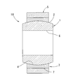
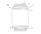
- the spherical plain bearing 10 is a combination of an inner ring 1 having a spherical sliding surface 2 on the outer periphery and an outer ring 3 having an inner peripheral surface 4 slidably contacting the sliding surface 2. And an outer ring member 5 fitted to the outer periphery of the outer ring 3.
- the inner ring 1 is a convex spherical surface whose outer peripheral surface is a sliding surface 2, and is made of a metallic cylindrical member whose inner peripheral surface is a cylindrical surface.
- the sliding surface 2 has a circular cross section in the radial direction.
- the inside of the inner peripheral surface of the inner ring 1 is a bearing hole 6 through which a support shaft (not shown) passes in the axial direction.
- the inner ring 1 is a plane in which both side surfaces in the axial direction are parallel to the radial plane, and the interval between the side surfaces is formed wider than the interval between the side surfaces of the outer ring 3.
- the outer ring 3 is composed of one strip-shaped metal plate 11 formed in a cylindrical shape, and the inner peripheral surface 4 is a spherical concave surface, and the outer peripheral surface 7 is a cylindrical surface.
- the inner peripheral surface 4 of the outer ring 3 has a circular cross-sectional shape in the radial direction, and the arc has the same or slightly larger radius of curvature than the arc of the sliding surface 2 of the inner ring 1.
- the outer ring member 5 is fitted on the outer peripheral surface 7 of the outer ring 3 by an interference fit.
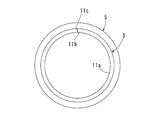
- one end 11b and the other end 11c of the metal plate 11 constituting the outer ring 3 are abutted against each other (see FIG. 4C).
- the inner peripheral surface 4 of the outer ring 3 is a continuous surface having no radial step.
- the outer ring 3 is made of a strip-shaped metal plate such as an aluminum alloy, stainless steel, or steel. Further, as will be described later, the outer ring 3 is formed into a cylindrical shape by bending a metal plate 11 so that one surface thereof becomes a concave surface 11a having an arc cross section and the concave surface 11a becomes an inner peripheral surface. It is formed.
- the outer ring member 5 is formed in a cylindrical shape, and an inner peripheral surface and an outer peripheral surface thereof are formed in a cylindrical surface.
- a housing (not shown) for attaching the spherical plain bearing 10 is fitted to the outer peripheral portion of the outer ring member 5.
- the material of the inner ring 1 and the outer ring member 5 is not particularly limited, and can be made of a metal such as an aluminum alloy, stainless steel, or steel, a synthetic resin, or a ceramic.
- the spherical plain bearing 10 of this embodiment is configured as described above, and both ends of the outer ring 3 made of the cylindrical metal plate 11 can be widened to combine the inner ring 1 inside the outer ring 3. For this reason, the combination of the inner ring 1 and the outer ring 3 becomes easy.
- the outer ring 3 is formed by fitting the outer ring member 5 to the outer peripheral surface 7 by an interference fit.
- the outer ring 3 can be finished on the inner circumferential surface 4 before the inner ring 1 is combined.
- the inner circumferential surface 4 of the outer ring 3 can improve the dimensional accuracy as a concave spherical surface.
- one surface of the strip-shaped metal plate 11 formed in a cylindrical shape is a concave surface 11 a
- the other surface of the metal plate 11 is an outer peripheral surface 7.
- the material of the outer ring 3 may be subjected to a finishing process such as a minimum necessary cutting or grinding process for forming the concave surface 11a on one surface of the metal plate 11. For this reason, it becomes possible to reduce the part removed by cutting etc. with respect to the material of the outer ring
- the outer ring 3 has the outer ring member 5 fitted on the outer peripheral surface 7 by an interference fit.
- the present invention is not limited to this.
- the outer ring 3 the outer ring member 5 can be directly fitted into the housing (not shown) by an interference fit without fitting. Even in this case, the outer ring 3 is in a state in which the one end 11b and the other end 11c of the metal plate 11 constituting the outer ring 3 are abutted with each other.
- FIGS. 3A to 3C and FIGS. 4A to 4C are views showing a manufacturing process of the spherical plain bearing 10.
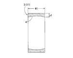
- a band-shaped metal plate 11 having the same width as the axial width W1 of the outer ring 3 is created.
- the thickness of the metal plate 11 is the same thickness as the distance a1 between the outer peripheral surface 7 of the outer ring 3 and the minimum inner diameter portion of the inner peripheral surface 4, and for example, the load capacity, the usage environment, and the usage of the spherical plain bearing 10 are used. It can be set by the device.
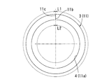
- the strip-shaped metal plate 11 is cut to the same length as the outer peripheral surface circumferential length L1 of the outer ring 3 shown in FIG. 2B. Thereafter, as shown in FIG. 3C, the strip-shaped metal plate 11 is inclined at the angle ⁇ 1 inward in the longitudinal direction from the other surface 11d toward the one surface at the one end portion 11b and the other end portion 11c in the length direction. Cutting to the state to do.
- the angle ⁇ 1 at the one end portion 11b and the other end portion 11c is the same length as the peripheral length L2 of the minimum inner diameter portion of the inner peripheral surface 4 of the outer ring 3 shown in FIG. It is prescribed by that.
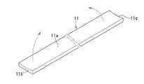
- a concave surface 11 a is formed by forging so that the cross-sectional shape in the width direction is an arc with respect to one surface of the metal plate 11.
- the radius of curvature of the arc that is the cross-sectional shape of the concave surface 11a in the width direction is the same as or slightly larger than the radius of curvature of the sliding surface 2 of the inner ring 1.
- the outer ring 3 is formed by bending the metal plate 11 into a cylindrical shape by abutting the one end portion 11b and the other end portion 11c with the concave surface 11a inside.
- the outer ring 3 When the bending process is finished and the bending stress is released, the outer ring 3 is in a state in which the one end 11b and the other end 11c are slightly separated as shown in FIG. 4B.
- the cylindrical outer ring member 5 is fitted to the outer periphery of the outer ring 3 by interference fitting. At this time, since the outer ring 3 is tightened by the outer ring member 5, the one end part 11b and the other end part 11c of the outer ring 3 are brought into contact with each other (see FIG. 4C).
- the concave surface 11 a that becomes the inner peripheral surface 4 of the outer ring 3 is finished so as to be a spherical surface along the sliding surface 2 of the inner ring 1.
- the outer ring 3 is in a state in which one end portion 11b and the other end portion 11c thereof are abutted with each other.
- the inner peripheral surface 4 of the outer ring 3 becomes a continuous surface without a step in the radial direction. Note that superfinishing can be performed instead of the finishing, and superfinishing may be performed after finishing.
- the outer ring member 5 is removed from the outer ring 3, the space between one end 11b and the other end 11c of the outer ring 3 is expanded, the outer ring 3 is expanded, and the inner ring 1 is combined inside.
- the inner ring 1 and the outer ring 3 are combined to form a spherical plain bearing 10.
- a housing (not shown) is fitted to the outer periphery of the outer ring 3 by an interference fit.
- the outer ring 3 is brought into a state where the one end part 11 b and the other end part 11 c are abutted, and the sliding surface 2 of the inner ring 1 can be smoothly slid with respect to the inner peripheral surface 4 of the outer ring 3. .
- the outer ring member 5 may be fitted to the outer peripheral part of the outer ring 3 by an interference fit, and the one end 11b and the other end 11c of the outer ring 3 may be joined.
- this joining method an existing method such as arc welding or spot welding can be used.
- the spherical plain bearing 20 of this embodiment includes an outer ring member 5 in that the outer ring 3 is formed of a cylindrical member that is seamless in the radial direction, and the inner ring 1 is formed of a band-shaped metal plate 21 formed in a cylindrical shape. This is different from the first embodiment described above. In other configurations, the same configurations as those of the first embodiment are denoted by the same reference numerals, and the description thereof is omitted.
- the spherical plain bearing 20 of this embodiment includes a combination of an inner ring 1 having a spherical sliding surface 2 on the outer periphery and an outer ring 3 having an inner peripheral surface 4 slidably contacting the sliding surface 2. It will be.
- the inner ring 1 is composed of one strip-shaped metal plate 21 formed in a cylindrical shape, and has a sliding surface 2 that is a spherical surface on the outer periphery and an inner peripheral surface that is a cylindrical surface on the inner periphery.
- the inside of the inner peripheral surface of the inner ring 1 has a bearing hole 6 through which a support shaft (not shown) passes in the axial direction.
- the inner ring 1 is a plane in which both side surfaces in the axial direction are parallel to the radial plane, and the axial width W2 defined as the interval between the side surfaces is wider than the interval between the side surfaces of the outer ring 3. It is formed (see FIG. 5).
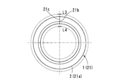
- the inner ring 1 has one end 21b and the other end 21c of a metal plate 21 constituting the inner ring 1 attached to each other (see FIG. 6B).
- the sliding surface 2 of the inner ring 1 is a continuous surface having no radial step.
- the inner ring 1 is composed of a strip-shaped metal plate 21 such as an aluminum alloy, stainless steel, or steel. Further, as will be described later, the inner ring 1 is formed so that one surface of the metal plate 21 becomes a convex surface 21a whose cross-sectional shape in the width direction is an arc, and the convex surface 21a becomes a sliding surface 2 Is formed in a cylindrical shape.
- the outer ring 3 is made of a metallic cylindrical member having an outer peripheral surface 7 that is a cylindrical surface and an inner peripheral surface 4 that is a concave spherical surface that protrudes radially outward.
- the inner peripheral surface 4 of the outer ring 3 has a circular cross section in the radial direction.
- the arc of the inner peripheral surface 4 of the outer ring 3 has the same or slightly larger radius of curvature than the arc of the sliding surface 2 of the inner ring 1.
- the material of the outer ring 3 is not particularly limited, and for example, a metal such as an aluminum alloy, stainless steel, or steel, a synthetic resin, or a ceramic can be employed.
- the spherical plain bearing 20 of the second embodiment is configured, and in the inner ring 1, one surface of the strip-shaped metal plate 21 formed in a cylindrical shape becomes a convex surface 21 a, and the other surface of the metal plate 21. Is the inner surface.
- the material of the inner ring 1 may be subjected to a finishing process such as a minimum necessary cutting or grinding process for forming the convex surface 21a on one surface of the metal plate 21. This makes it possible to reduce the portion to be removed and improve the material yield.
- FIG. 7A, FIG. 7B, FIG. 8A, and FIG. 8B are diagrams showing manufacturing steps of the spherical plain bearing 20.
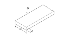
- the inner ring 1 has the same width as the axial width W2, and the distance between the inner peripheral surface of the inner ring 1 and the maximum outer diameter portion of the sliding surface 2 is as follows.
- a strip-shaped metal plate 21 having the same thickness as a2 is created.
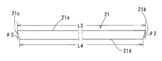
- the strip-shaped metal plate 21 is cut to the same length as the sliding surface circumferential length L3 at the maximum outer diameter portion of the sliding surface 2 of the inner ring 1 shown in FIG. 6B.
- the band-shaped metal plate 21 is inclined inward in the length direction from one surface to the other surface 21d at one end 21b and the other end 21c in the length direction. Cutting in an inclined state.
- the angle ⁇ 2 at the one end 21b and the other end 21c is defined by setting the length on the other surface 21d side of the metal plate 21 to the same length as the inner peripheral surface circumferential length L4 of the inner ring 1 shown in FIG. 6B. Is done.
- a convex surface 21a is formed on one surface of the metal plate 21 by forging so that the cross-sectional shape in the width direction becomes an arc.
- the metal plate 21 is bent into a cylindrical shape by abutting the one end 21b and the other end 21c with the convex surface 21a facing outward.
- the one end 21b and the other end 21c of the inner ring 1 are joined together by welding in a state where they are butted.
- the convex surface 21a of the joined inner ring 1 is finished so as to be a spherical surface along the inner circumferential surface 4 of the outer ring 3, thereby forming the inner ring 1 (see FIG. 6B).
- the inner ring 1 is in a state where the one end 21b and the other end 21c are abutted against each other.
- the sliding surface 2 of the inner ring 1 becomes a continuous surface without a step in the radial direction. Note that superfinishing can be performed instead of the finishing, and superfinishing may be performed after finishing.
- a spherical plain bearing 20 is configured by this combination.
- the thickness of the metal plate 21 is the same as the distance a ⁇ b> 2 between the inner peripheral surface of the inner ring 1 and the maximum outer diameter portion of the sliding surface 2.
- the other surface 21 d of the metal plate 21 becomes the inner peripheral surface of the inner ring 1.
- wheel 1 of this embodiment consists of the one strip
- a band-shaped metal plate 21 is formed from three band-shaped divided bodies 22 having an arc shape, and each band-shaped divided body 22 is in a cylindrical shape.
- the inner ring 1 shown in FIG. 10 can also be configured by joining together by welding.
- the inner ring 1 one end portion 21b and the other end portion 21c of a single band-shaped metal plate 21 formed in a cylindrical shape are joined by welding, but the joining means is not limited to welding.
- the inner ring 1 may have a circumferential groove 1 a formed on the entire circumference of the sliding surface 2.
- the one end 21b and the other end 21c of the metal plate 21 can be joined by the fixed band 30 wound around the circumferential groove 1a.
- the inner ring 1 has a sliding surface 2 on the entire outer peripheral surface, but is not limited thereto.
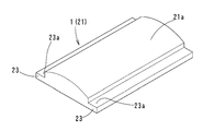
- cylindrical surfaces 23a and 23a may be provided on both sides in the axial direction of the sliding surface 2.
- the metal plate 21 is integrally formed with a protruding portion 23 that protrudes outward in the width direction over the entire length of the convex surface 21 a that becomes the sliding surface 2.
- the outer peripheral surfaces of the protruding portions 23 become cylindrical surfaces 23a and 23a.
- the cylindrical surface 23 a is located on the radially inner side with respect to the convex surface 21 a serving as the sliding surface 2.
Landscapes
- Engineering & Computer Science (AREA)
- General Engineering & Computer Science (AREA)
- Mechanical Engineering (AREA)
- Support Of The Bearing (AREA)
Abstract
材料の歩留りの向上を図ることができる球面滑り軸受を提供する。外周に球面の摺動面(2)を有する内輪(1)と、内輪(1)の摺動面(2)に摺接する内周面(4)を有する外輪(3)との組み合わせからなり、外輪(3)は、円筒状に形成される帯状の金属板からなり、その金属板は、一方の表面に幅方向の断面形状が円弧となる凹面を有するものであり、その一方の表面を外輪(3)の内周面(4)としたものである。
Description
この発明は、荷重を受けつつ揺動運動し、かつ軸の傾きを許容する球面滑り軸受およびその製造方法に関する。
従来、球面滑り軸受は、凸球面の摺動面を有する内輪と、凹球面の摺動面を有する外輪とを組み合わせたものであって、荷重を受けつつ回転運動あるいは揺動運動し、かつ軸の傾きを許容するように構成されている。
この種の従来の球面滑り軸受の内輪は、金属製の棒材またはパイプ材等の材料を切断し、切削、研削加工などにより、凸球面をなす外周面および円筒面をなす内周面を形成することで製作されていた。
また、外輪も同様に、金属製の棒材またはパイプ材等の材料を切断し、切削、研削加工などにより、円筒面をなす外周面および凹球面をなす内周面を形成することで製作されていた(例えば、下記特許文献1参照)。
特許文献1に記載された球面滑り軸受では、内輪または外輪の製作の際、上記材料を所定の寸法となるまでに、切削、研削して取り除く必要がある。特に、棒材などの中実の素材から内輪の内外周面または外輪の内周面を形成する際、素材の多くの部分を取り除く必要があることから、材料の歩留りが悪いという問題があった。
そこで、この発明が解決すべき課題としては、材料の歩留りの向上を図ることができる球面滑り軸受を提供することにある。
上記の課題を解決するために、この発明は、外周に球面の摺動面を有する内輪と、前記内輪の摺動面に摺接する内周面を有する外輪との組み合わせからなる球面滑り軸受であって、
前記外輪は、円筒状に形成される帯状の金属板からなり、前記金属板は、一方の表面に幅方向の断面形状が円弧となる凹面を有するものであり、前記一方の表面が前記外輪の内周面とされた構成を採用することができる。
前記外輪は、円筒状に形成される帯状の金属板からなり、前記金属板は、一方の表面に幅方向の断面形状が円弧となる凹面を有するものであり、前記一方の表面が前記外輪の内周面とされた構成を採用することができる。
この構成によると、円筒状に形成される帯状の金属板の一方の表面が、外輪の上記凹面となり、その金属板の他方の表面が外輪の外周面となる。
また、金属板からなる円筒状の外輪の両端部を広げて、外輪の内周部に内輪を容易に嵌め合わせることができる。
この構成において、前記外輪がその外周部に締まり嵌めにより嵌合される円筒状の外環部材を備え、その外環部材が嵌合された前記外輪は、その一端部および他端部が相互に突き当たる状態となる構成を採用することができる。
この構成によると、外環部材が外周部に嵌り合う外輪は、その内周面に対して内輪の摺動面に沿う球面となるように仕上げ加工を行うことが可能となる。このため、外輪の内周面の寸法精度を向上させることができる。
また、外環部材を外輪の外周部から取り外すことにより、外輪の内周部に内輪を嵌め合わせることができる。さらに、内周部に内輪が嵌め合わされた外輪は、その外周部に外環部材を嵌め合わせることで、外輪からの内輪の脱落を防止することができる。
上記課題を解決するために、この発明は、外周に球面の摺動面を有する内輪と、前記内輪の摺動面に摺接する内周面を有する外輪とからなる球面滑り軸受の製造方法であって、
帯状の金属板の一方の表面に鍛造加工により幅方向の断面形状が円弧となるように凹面を形成し、
前記金属板を前記凹面が内側となる状態で、前記金属板の一端部と他端部を突き合わせて円筒状とする曲げ加工して、前記一方の表面を内周面とする前記外輪を形成し、
前記外輪の外周部に外環部材を締まり嵌めにより嵌め合わせ、
前記外輪の凹面を前記内輪の摺動面に沿う球面となるように仕上げ加工を施し、
前記外輪を前記外環部材から取り外し、
前記外輪の内側に前記内輪を組み合わせた方法を採用することができる。
帯状の金属板の一方の表面に鍛造加工により幅方向の断面形状が円弧となるように凹面を形成し、
前記金属板を前記凹面が内側となる状態で、前記金属板の一端部と他端部を突き合わせて円筒状とする曲げ加工して、前記一方の表面を内周面とする前記外輪を形成し、
前記外輪の外周部に外環部材を締まり嵌めにより嵌め合わせ、
前記外輪の凹面を前記内輪の摺動面に沿う球面となるように仕上げ加工を施し、
前記外輪を前記外環部材から取り外し、
前記外輪の内側に前記内輪を組み合わせた方法を採用することができる。
前記方法の後に、さらに、前記外輪の外周部に前記外環部材を締まり嵌めにより嵌め合わせ、前記外輪の一端部および他端部を接合した方法を採用することができる。
また、上記の課題を解決するために、この発明は、外周に球面の摺動面を有する内輪と、前記内輪の摺動面に摺接する内周面を有する外輪との組み合わせからなる球面滑り軸受であって、
前記内輪は、円筒状に形成される帯状の金属板からなり、前記金属板は、一方の表面に幅方向の断面形状が円弧となる凸面を有するものであり、前記一方の表面が前記内輪の摺動面とされた構成を採用することができる。
前記内輪は、円筒状に形成される帯状の金属板からなり、前記金属板は、一方の表面に幅方向の断面形状が円弧となる凸面を有するものであり、前記一方の表面が前記内輪の摺動面とされた構成を採用することができる。
この構成によると、円筒状に形成される帯状の金属板の一方の表面が、内輪の上記凸面となり、その金属板の他方の表面が内輪の内周面となる。
上記構成において、前記金属板は、円弧状をなす複数の帯状分割体が円筒状に接合されたものであり、それぞれの前記帯状分割体が、その一方の表面に前記凸面を有する構成を採用することができる。
この場合、外輪の内周部において、円筒状に配置された複数の帯状分割体を接合して内輪とすることができるので、外輪の内周部に内輪を容易に嵌め合せることができる。
さらに、前記金属板が前記一方の表面において、前記凸面の軸方向両側にその凸面よりも径方向内側に位置する円筒面を有する構成や、前記内輪がその凸面に周溝を有する構成を採用することができる。
さらに、上記の課題を解決するために、この発明は、外周に球面の摺動面を有する内輪と、前記内輪の摺動面に摺接する内周面を有する外輪とからなる球面滑り軸受の製造方法であって、
帯状の金属板の一方の表面に鍛造加工により幅方向の断面形状が円弧となるように凸面を形成し、
前記金属板を前記凸面が外側となる状態で、前記金属板の一端部と他端部を突き合わせて円筒状とする曲げ加工し、前記一方の表面を前記摺動面とする前記内輪を形成し、
前記内輪の凸面を前記外輪の内周面に沿う球面となるように仕上げ加工を施し、
前記外輪の内側に前記内輪を組み合わせた製造方法を採用することができる。
帯状の金属板の一方の表面に鍛造加工により幅方向の断面形状が円弧となるように凸面を形成し、
前記金属板を前記凸面が外側となる状態で、前記金属板の一端部と他端部を突き合わせて円筒状とする曲げ加工し、前記一方の表面を前記摺動面とする前記内輪を形成し、
前記内輪の凸面を前記外輪の内周面に沿う球面となるように仕上げ加工を施し、
前記外輪の内側に前記内輪を組み合わせた製造方法を採用することができる。
この発明は、外輪は、金属板の一方の表面に対し、鍛造加工等を行うことによって、球面である上記凹面を形成することができる。このため、外輪となる材料に対して、研削加工等により取り除く部分が減り、その材料の歩留りの向上を図ることができる。
また、内輪は、金属板の一方の表面に対し、鍛造加工等を行うことによって、球面である上記凸面を形成することができる。このため、内輪となる材料に対して、研削加工等により取り除く部分が減り、その材料の歩留りの向上を図ることができる。
以下、この発明の第一の実施形態に係る球面滑り軸受を図1に基づいて説明する。この実施形態に係る球面滑り軸受10は、図1に示すように、外周に球面の摺動面2を有する内輪1と、摺動面2に摺接する内周面4を有する外輪3との組み合わせからなり、外輪3の外周部に嵌合する外環部材5を備える。
内輪1は、外周面が摺動面2となる凸状の球面であり、内周面が円筒面である金属製の筒状部材からなる。摺動面2は、径方向の断面形状が円弧となっている。内輪1の内周面の内部は、支持軸(図示省略)が軸方向に貫通する軸受孔6とされる。
また、内輪1は、軸方向の両側面がラジアル平面に平行な平面であり、それぞれの側面の間隔は、外輪3のそれぞれの側面の間隔よりも広く形成されている。
外輪3は、円筒状に形成された一つの帯状の金属板11からなり、内周面4が球状の凹面であり、外周面7が円筒面をなしている。外輪3の内周面4は、径方向の断面形状が円弧であり、その円弧は、内輪1の摺動面2の円弧に対して、同じまたはわずかに大きい曲率半径を有している。
外輪3の外周面7には、外環部材5が締まり嵌めにより嵌め合わされている。外環部材5が嵌め合わされる外輪3は、これを構成する金属板11の一端部11bおよび他端部11cが相互に突き合わされている(図4C参照)。この突き合わせ部分において、外輪3の内周面4は径方向の段差のない連続面となっている。
外輪3は、アルミニウム合金、ステンレス鋼、鉄鋼などの帯状の金属板からなる。また、外輪3は、後述のように、金属板11をその一方の表面が断面円弧状の凹面11aとなるように形成して、凹面11aが内周面となるように曲げ加工により円筒状に形成されたものである。
外環部材5は、円筒状に形成され、その内周面および外周面が円筒面に形成される。外環部材5の外周部に球面滑り軸受10を取り付けるハウジング(図示省略)が嵌め合わされている。
内輪1および外環部材5の材質は、特に限定されず、例えば、アルミニウム合金、ステンレス鋼、鉄鋼などの金属製や、合成樹脂製、セラミックス製とすることができる。
この実施形態の球面滑り軸受10は、上述のように構成され、円筒状の金属板11からなる外輪3の両端部を広げて、外輪3の内側に内輪1を組み合わせることができる。このため、内輪1と外輪3との組み合わせが容易になる。
また、外輪3は、外周面7に外環部材5が締まり嵌めにより嵌め合わされているものである。この外輪3は、内輪1を組み合わせる前に、その内周面4に対して、仕上げ加工を施すことができる。その結果、外輪3の内周面4は、凹面である球面としての寸法精度を向上させることができる。
さらに、外輪3は、円筒状に形成される帯状の金属板11の一方の表面が、凹面11aとなり、金属板11の他方の表面が外周面7となる。このような外輪3の材料は、金属板11の一方の表面に凹面11aを形成するための必要最小限の切削または研削加工等の仕上げ加工を行えばよい。このため、外輪3の材料に対して、切削加工等により取り除く部分を減らすことが可能となり、材料の歩留りを向上させることができる。
なお、この実施形態において、外輪3は、その外周面7に外環部材5が締まり嵌めにより嵌め合わされているが、これに限られない。例えば、外輪3としては、外環部材5を嵌め合わせずに、ハウジング(図示省略)の内部に締まり嵌めにより直接嵌め合わせることもできる。この場合においても、外輪3は、これを構成する金属板11の一端部11bおよび他端部11cが相互に突き合わされた状態となる。
次に、第一の実施形態の球面滑り軸受10の製造方法を図面に基づいて説明する。図3A~図3C、図4A~図4Cは、球面滑り軸受10の製造工程を示す図である。
上記製造方法としては、まず、図3Aに示すように、外輪3の軸幅W1と同じ幅寸法を有する帯状の金属板11を作成する。ここで、金属板11の厚みは、外輪3の外周面7と内周面4の最小内径部との間隔a1と同じ厚みであり、例えば、球面滑り軸受10の負荷容量、使用環境、使用される装置により設定することができる。
その帯状の金属板11を、図2Bに示す外輪3の外周面周長L1と同じ長さに切断する。その後、図3Cに示すように、帯状の金属板11を長さ方向の一端部11bおよび他端部11cにおいて、他方の表面11dから一方の表面に向かって長さ方向内向きに角度θ1をもって傾斜する状態に切削加工をする。
一端部11bおよび他端部11cでの角度θ1は、金属板11の一方の表面側での長さを、図2Bに示す外輪3の内周面4の最小内径部の周長L2と同じ長さとすることで規定される。
次に、図3Bに示すように、鍛造加工により、金属板11の一方の表面に対して幅方向の断面形状が円弧となるように凹面11aを形成する。このとき、凹面11aの幅方向断面形状である円弧の曲率半径は、内輪1の摺動面2の曲率半径と同じまたはわずかに大きいものである。これにより、外輪3の内周面4を内輪1の摺動面2に沿う状態とすることができる。
続いて、図4Aに示すように、金属板11を凹面11aが内側となる状態で一端部11bおよび他端部11cを相互に突き合わせて円筒状とする曲げ加工をし、外輪3を形成する。
この曲げ加工が終わり、曲げ応力が開放されると、図4Bに示すように、外輪3は、その一端部11bおよび他端部11cがわずかに離れた状態となる。
曲げ加工後に、外輪3の外周部に円筒状の外環部材5を締まり嵌めにより嵌め合わせる。このとき、外環部材5により外輪3は締め付けられるため、外輪3の一端部11bおよび他端部11cが相互に突き合わされた状態となる(図4C参照)。
そして、外輪3の内周面4となる凹面11aを、内輪1の摺動面2に沿う球面となるように仕上げ加工を施す。ここで、外輪3はその一端部11bおよび他端部11cが相互に突き合わされた状態となっている。
その突き合わせ部分を含めた凹面11aの全周に仕上げ加工を施すことにより、外輪3の内周面4は径方向の段差のない連続面となる。なお、上記仕上げ加工の代わりに、超仕上げ加工を行うことも可能であり、仕上げ加工後に超仕上げ加工を行ってもよい。
仕上げ加工後、外環部材5を外輪3から取り外し、外輪3の一端部11bと他端部11cとの間を広げて、外輪3を拡径して内側に内輪1を組み合わせる。このように内輪1と外輪3とが組み合わされて、球面滑り軸受10が構成される。
この球面滑り軸受10は、外輪3の外周部にハウジング(図示省略)が締まり嵌めにより嵌め合わされる。この嵌め合わせにより、外輪3は、一端部11bおよび他端部11cが突き合わされた状態となり、外輪3の内周面4に対して内輪1の摺動面2を円滑に摺動させることができる。
なお、外輪3の内側に内輪1を組み合わせた後に、外輪3の外周部に外環部材5を締まり嵌めにより嵌め合わせ、外輪3の一端部11bおよび他端部11cを接合してもよい。この接合方法として、アーク溶接やスポット溶接など既存の工法を用いることができる。
次に、この発明の第二の実施形態に係る球面滑り軸受を図5、図6A、図6Bに基づいて説明する。
この実施形態の球面滑り軸受20は、外輪3が径方向に継ぎ目のない筒状部材から形成され、内輪1が円筒状に形成された帯状の金属板21からなる点、外環部材5を備えていない点で、上述した第一の実施形態と相違する。その他の構成において、第一の実施形態と同じ構成と考えられるものは、同じ符号を付して、その説明を省略する。
この実施形態の球面滑り軸受20は、外輪3が径方向に継ぎ目のない筒状部材から形成され、内輪1が円筒状に形成された帯状の金属板21からなる点、外環部材5を備えていない点で、上述した第一の実施形態と相違する。その他の構成において、第一の実施形態と同じ構成と考えられるものは、同じ符号を付して、その説明を省略する。
この実施形態の球面滑り軸受20は、図5に示すように、外周に球面の摺動面2を有する内輪1と、摺動面2に摺接する内周面4を有する外輪3との組み合わせからなるものである。
内輪1は、円筒状に形成された一つの帯状の金属板21からなり、外周に球面となる摺動面2と、内周に円筒面となる内周面を有する。内輪1の内周面の内部は、支持軸(図示省略)が軸方向に貫通する軸受孔6を有する。
内輪1は、図6Aに示すように、軸方向の両側面がラジアル平面に平行な平面であり、それぞれの側面の間隔とされる軸幅W2は、外輪3のそれぞれの側面の間隔よりも広く形成されている(図5参照)。
内輪1は、これを構成する金属板21の一端部21b、他端部21cが相互に付き合わされている(図6B参照)。この突き合わせ部分において、内輪1の摺動面2は径方向の段差のない連続面となっている。
内輪1は、アルミニウム合金、ステンレス鋼、鉄鋼などの帯状の金属板21からなる。また、内輪1は、後述のように、金属板21の一方の表面が幅方向の断面形状が円弧である凸面21aとなるように形成され、凸面21aが摺動面2となるように曲げ加工により円筒状に形成されたものである。
外輪3は、外周面7が円筒面となり、かつ内周面4が径方向外向きに突出する凹状の球面となる金属製の筒状部材からなる。外輪3の内周面4は、径方向の断面形状が円弧をなしている。外輪3の内周面4の円弧は、内輪1の摺動面2の円弧に対して、同じまたはわずかに大きい曲率半径を有している。
外輪3の材質は、特に限定されず、例えば、アルミニウム合金、ステンレス鋼、鉄鋼などの金属製や、合成樹脂製、セラミック製などを採用することができる。
以上のように第二の実施形態の球面滑り軸受20は構成され、内輪1は、円筒状に形成される帯状の金属板21の一方の表面が、凸面21aとなり、金属板21の他方の表面が内周面となる。
この内輪1の材料は、金属板21の一方の表面に凸面21aを形成するための必要最小限の切削または研削加工等の仕上げ加工を行えばよく、内輪1の材料に対して、切削加工等により取り除く部分を減らすことが可能となり、材料の歩留りを向上させることができる。
次に、第二の実施形態の球面滑り軸受20の製造方法を図面に基づいて説明する。図7A、図7B、図8A、図8Bは、球面滑り軸受20の製造工程を示す図である。
上記製造方法としては、まず、図7Aに示すように、内輪1の軸幅W2と同じ幅寸法を有し、かつ、内輪1の内周面と摺動面2の最大外径部との間隔a2と同じ厚みを有する帯状の金属板21を作成する。その帯状の金属板21を、図6Bに示す内輪1の摺動面2の最大外径部での摺動面周長L3と同じ長さに切断する。
その後、図7Bに示すように、帯状の金属板21を、長さ方向の一端部21bおよび他端部21cにおいて、一方の表面から他方の表面21dへ向かって長さ方向内向きに角度θ2をもって傾斜する状態に切削加工をする。
一端部21bおよび他端部21cでの角度θ2は、金属板21の他方の表面21d側での長さを、図6Bに示す内輪1の内周面周長L4と同じ長さとすることで規定される。
続いて、図8Aに示すように、金属板21の一方の表面に対して、鍛造加工により、幅方向の断面形状が円弧となるように凸面21aを形成する。
その後、図8Bに示すように、金属板21を凸面21aが外側となる状態で一端部21bおよび他端部21cを相互に突き合わせて円筒状とする曲げ加工をする。
曲げ加工の後、内輪1の一端部21bおよび他端部21cを突き合わせた状態で溶接により接合する。接合された内輪1の凸面21aを、外輪3の内周面4に沿う球面となるように仕上げ加工を行い、内輪1を形成する(図6B参照)。
ここで、内輪1はその一端部21bおよび他端部21cが相互に突き合わされた状態となっている。その突き合わせ部分を含めた凸面21aの全周に仕上げ加工を施すことにより、内輪1の摺動面2は径方向の段差のない連続面となる。なお、上記仕上げ加工の代わりに、超仕上げ加工を行うことも可能であり、仕上げ加工後に超仕上げ加工を行ってもよい。
仕上げ加工後、外輪3の内周面4に内輪1の摺動面2を摺動させながら、外輪3の内側に内輪1を組み合わせる。この組み合わせにより、球面滑り軸受20が構成される。
この内輪1の製造方法では、金属板21の厚さは、内輪1の内周面と摺動面2の最大外径部との間隔a2と同じ厚みとしている。このような金属板21に対して円筒状に曲げ加工を施すと、金属板21の他方の表面21dが内輪1の内周面となる。
このため、金属板21の一方の表面に対して、凸面21aを形成するための必要最小限の切削または研削加工等の仕上げ加工を行えばよく、内輪1の材料となる金属板21に対して切削加工等により取り除く部分を減らすことが可能となり、内輪1の材料の歩留りを向上させることができる。
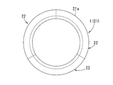
なお、この実施形態の内輪1は、円筒状に形成された一本の帯状の金属板21からなるものであるが、これに限られない。例えば、内輪1の変形例としては、図9に示すように、帯状の金属板21を円弧状をなす三本の帯状分割体22から形成し、それぞれの帯状分割体22を円筒状となる状態で溶接により接合し、図10に示す内輪1を構成することもできる。
また、内輪1は、円筒状に形成された一本の帯状の金属板21の一端部21bと他端部21cとが溶接により接合されるものであるが、接合の手段は溶接に限られない。例えば、図11に示すように、内輪1が摺動面2の全周に形成された周溝1aを有するものとしてもよい。この周溝1a内に巻き付けた固定バンド30により、金属板21の一端部21bと他端部21cとを接合することができる。
また、内輪1は、外周面の全面が摺動面2となっているが、これに限られない。例えば、内輪1の他の変形例としては、図12Aに示すように、摺動面2の軸方向両側に円筒面23a、23aを有するものとしてもよい。この場合、図12Bに示すように、金属板21に、摺動面2となる凸面21aの全長にわたり幅方向外向きに突き出す突出部23を一体に形成する。
突出部23を形成した金属板21を円筒状に折り曲げ加工すると、ぞれぞれの突出部23の外周面が円筒面23a、23aとなる。円筒面23aは、摺動面2となる凸面21aよりも、径方向内側に位置している。これらの円筒面23aのそれぞれに、固定バンド30を巻き付けることで、金属板21の一端部21bと他端部21cとを相互に接合することができる。
1 内輪
1a 周溝
2 摺動面
3 外輪
4 内周面
5 外環部材
6 軸受孔
7 外周面
10、20 球面滑り軸受
11、21 金属板
11a 凹面
11b、21b 一端部
11c、21c 他端部
11d、21d 他方の表面
21a 凸面
22 帯状分割体
23 突出部
23a 円筒面
30 固定バンド
a1、a2 間隔
L1 外周面周長
L2 周長
L3 摺動面周長
L4 内周面周長
W1、W2 軸幅
θ1、θ2 角度
1a 周溝
2 摺動面
3 外輪
4 内周面
5 外環部材
6 軸受孔
7 外周面
10、20 球面滑り軸受
11、21 金属板
11a 凹面
11b、21b 一端部
11c、21c 他端部
11d、21d 他方の表面
21a 凸面
22 帯状分割体
23 突出部
23a 円筒面
30 固定バンド
a1、a2 間隔
L1 外周面周長
L2 周長
L3 摺動面周長
L4 内周面周長
W1、W2 軸幅
θ1、θ2 角度
Claims (10)
- 外周に球面の摺動面(2)を有する内輪(1)と、前記内輪(1)の摺動面(2)に摺接する内周面(4)を有する外輪(3)との組み合わせからなる球面滑り軸受(10)であって、
前記外輪(3)は、円筒状に形成される帯状の金属板(11)からなり、前記金属板(11)は、一方の表面に幅方向の断面形状が円弧となる凹面(11a)を有するものであり、前記一方の表面が前記外輪(3)の内周面(4)とされた球面滑り軸受。 - 前記外輪(3)がその外周部に締まり嵌めにより嵌合される円筒状の外環部材(5)を備え、その外環部材(5)が嵌合された前記外輪(3)は、その一端部(11b)および他端部(11c)が相互に突き当たる状態となる請求項1に記載された球面滑り軸受。
- 外周に球面の摺動面(2)を有する内輪(1)と、前記内輪(1)の摺動面(2)に摺接する内周面(4)を有する外輪(3)とからなる球面滑り軸受の製造方法であって、
帯状の金属板(11)の一方の表面に鍛造加工により幅方向の断面形状が円弧となるように凹面(11a)を形成し、
前記金属板(11)を前記凹面(11a)が内側となる状態で、前記金属板(11)の一端部(11b)と他端部(11c)を突き合わせて円筒状とする曲げ加工して、前記一方の表面を内周面(4)とする前記外輪(3)を形成し、
前記外輪(3)の外周部に外環部材(5)を締まり嵌めにより嵌め合わせ、
前記外輪(3)の凹面(11a)を前記内輪(1)の摺動面(2)に沿う球面となるように仕上げ加工を施し、
前記外輪(3)を前記外環部材(5)から取り外し、
前記外輪(3)の内側に前記内輪(1)を組み合わせた球面滑り軸受の製造方法。 - 前記外輪(3)の外周部に前記外環部材(5)を締まり嵌めにより嵌め合わせ、前記外輪(3)の一端部(11b)および他端部(11c)を接合した請求項3に記載された球面滑り軸受の製造方法。
- 外周に球面の摺動面(2)を有する内輪(1)と、前記内輪(1)の摺動面(2)に摺接する内周面(4)を有する外輪(3)との組み合わせからなる球面滑り軸受(20)であって、
前記内輪(1)は、円筒状に形成される帯状の金属板(21)からなり、前記金属板(21)は、一方の表面に幅方向の断面形状が円弧となる凸面(21a)を有するものであり、前記一方の表面が前記内輪(1)の前記摺動面(2)とされた球面滑り軸受。 - 前記金属板(21)は、円弧状をなす複数の帯状分割体(22)が円筒状に接合されたものであり、前記それぞれの帯状分割体(22)が、その一方の表面に前記凸面(21a)を有する請求項5に記載された球面滑り軸受。
- 前記金属板(21)が前記一方の表面において、前記凸面(21a)の軸方向両側にその凸面(21a)よりも径方向内側に位置する円筒面(23a)を有する請求項5または6に記載された球面滑り軸受。
- 前記内輪(1)がその凸面(21a)に周溝(1a)を有する請求項5または6に記載された球面滑り軸受。
- 外周に球面の摺動面(2)を有する内輪(1)と、前記内輪(1)の摺動面(2)に摺接する内周面(4)を有する外輪(3)とからなる球面滑り軸受の製造方法であって、
帯状の金属板(21)の一方の表面に鍛造加工により幅方向の断面形状が円弧となるように凸面(21a)を形成し、
前記金属板(21)を前記凸面(21a)が外側となる状態で、前記金属板(21)の一端部(21b)と他端部(21c)を突き合わせて円筒状とする曲げ加工し、前記一方の表面を摺動面(2)とする前記内輪(1)を形成し、
前記内輪(1)の凸面(21a)を前記外輪(3)の内周面(4)に沿う球面となるように仕上げ加工を施し、
前記外輪(3)の内側に前記内輪(1)を組み合わせた球面滑り軸受の製造方法。 - 前記曲げ加工の前に、前記帯状の金属板(21)の両端部(21b、21c)を前記一方の表面から他方の表面(21d)に向かって長さ方向内向きに傾斜する状態に形成する請求項9に記載された球面滑り軸受の製造方法。
Applications Claiming Priority (4)
| Application Number | Priority Date | Filing Date | Title |
|---|---|---|---|
| JP2017-089182 | 2017-04-28 | ||
| JP2017089182 | 2017-04-28 | ||
| JP2018-079507 | 2018-04-18 | ||
| JP2018079507A JP2018189233A (ja) | 2017-04-28 | 2018-04-18 | 球面滑り軸受およびその製造方法 |
Publications (1)
| Publication Number | Publication Date |
|---|---|
| WO2018199232A1 true WO2018199232A1 (ja) | 2018-11-01 |
Family
ID=63920391
Family Applications (1)
| Application Number | Title | Priority Date | Filing Date |
|---|---|---|---|
| PCT/JP2018/016991 Ceased WO2018199232A1 (ja) | 2017-04-28 | 2018-04-26 | 球面滑り軸受およびその製造方法 |
Country Status (1)
| Country | Link |
|---|---|
| WO (1) | WO2018199232A1 (ja) |
Cited By (1)
| Publication number | Priority date | Publication date | Assignee | Title |
|---|---|---|---|---|
| CN112128238A (zh) * | 2020-09-25 | 2020-12-25 | 无锡优尼福科技有限公司 | 一种关节轴承及其制备方法 |
Citations (5)
| Publication number | Priority date | Publication date | Assignee | Title |
|---|---|---|---|---|
| US3452415A (en) * | 1966-11-25 | 1969-07-01 | Glacier Metal Co Ltd | Method of making a joint of the ball and socket type |
| US3526940A (en) * | 1968-06-26 | 1970-09-08 | Glacier Metal Co Ltd | Method of manufacturing a joint of the ball and socket type |
| GB1310984A (en) * | 1969-08-20 | 1973-03-21 | Elges H | Self-aligning bearing |
| JPH0596545U (ja) * | 1992-05-29 | 1993-12-27 | エヌティエヌ株式会社 | 球面軸受 |
| JP2000027854A (ja) * | 1998-05-15 | 2000-01-25 | Rexnord Corp | 直径方向分割複合球状ベアリングおよびその製造方法 |
-
2018
- 2018-04-26 WO PCT/JP2018/016991 patent/WO2018199232A1/ja not_active Ceased
Patent Citations (5)
| Publication number | Priority date | Publication date | Assignee | Title |
|---|---|---|---|---|
| US3452415A (en) * | 1966-11-25 | 1969-07-01 | Glacier Metal Co Ltd | Method of making a joint of the ball and socket type |
| US3526940A (en) * | 1968-06-26 | 1970-09-08 | Glacier Metal Co Ltd | Method of manufacturing a joint of the ball and socket type |
| GB1310984A (en) * | 1969-08-20 | 1973-03-21 | Elges H | Self-aligning bearing |
| JPH0596545U (ja) * | 1992-05-29 | 1993-12-27 | エヌティエヌ株式会社 | 球面軸受 |
| JP2000027854A (ja) * | 1998-05-15 | 2000-01-25 | Rexnord Corp | 直径方向分割複合球状ベアリングおよびその製造方法 |
Cited By (1)
| Publication number | Priority date | Publication date | Assignee | Title |
|---|---|---|---|---|
| CN112128238A (zh) * | 2020-09-25 | 2020-12-25 | 无锡优尼福科技有限公司 | 一种关节轴承及其制备方法 |
Similar Documents
| Publication | Publication Date | Title |
|---|---|---|
| JP5678165B2 (ja) | 分割型軸受リングの製造方法 | |
| JP2005337352A (ja) | 二つ割り外輪、それを用いた二つ割りころ軸受、ならびに二つ割り外輪の製造方法 | |
| JP6631066B2 (ja) | ラジアルニードル軸受用保持器の製造方法 | |
| JP5966554B2 (ja) | 波形保持器及びその製造方法 | |
| CN109154326A (zh) | 轴承密封装置 | |
| KR102507430B1 (ko) | 허브 유닛 베어링 및 그 제조 방법, 그리고, 자동차 및 그 제조 방법 | |
| WO2018199232A1 (ja) | 球面滑り軸受およびその製造方法 | |
| JP2009047239A (ja) | 溶接保持器および転がり軸受 | |
| JP2018189233A (ja) | 球面滑り軸受およびその製造方法 | |
| JP2011075091A (ja) | 軸受の分割外輪および分割外輪を備える軸受 | |
| TW201604445A (zh) | 滾珠螺桿裝置 | |
| JP3030486B2 (ja) | ころ軸受用保持器 | |
| EP3421828B1 (en) | Roller bearing | |
| CN105983641A (zh) | 将齿圈附接至差速器壳的方法、夹具及差速器壳 | |
| JP6595279B2 (ja) | 車輪用軸受装置の製造方法 | |
| JP5225700B2 (ja) | 転がり軸受ユニット | |
| JP2006029522A (ja) | 円すいころ軸受 | |
| JP2007270850A (ja) | 分割ころ軸受 | |
| JP4161658B2 (ja) | カムフォロアの製造方法 | |
| JP6511816B2 (ja) | 分割型軌道輪の製造方法 | |
| JP2007071344A (ja) | 船外機エンジンのクランク軸支持構造および船外機エンジン | |
| JP2009014164A (ja) | 鍔付円筒状部材の製造方法 | |
| JP2020153442A (ja) | 自動調心ころ軸受用の保持器及びその製造方法 | |
| JP2009281397A (ja) | 二つ割り外輪、及びこれを用いた二つ割り軸受 | |
| JP2013007447A (ja) | 回り止め付き軸受 |
Legal Events
| Date | Code | Title | Description |
|---|---|---|---|
| 121 | Ep: the epo has been informed by wipo that ep was designated in this application |
Ref document number: 18792233 Country of ref document: EP Kind code of ref document: A1 |
|
| NENP | Non-entry into the national phase |
Ref country code: DE |
|
| 122 | Ep: pct application non-entry in european phase |
Ref document number: 18792233 Country of ref document: EP Kind code of ref document: A1 |