WO2018199215A1 - ベーパーチャンバー - Google Patents
ベーパーチャンバー Download PDFInfo
- Publication number
- WO2018199215A1 WO2018199215A1 PCT/JP2018/016936 JP2018016936W WO2018199215A1 WO 2018199215 A1 WO2018199215 A1 WO 2018199215A1 JP 2018016936 W JP2018016936 W JP 2018016936W WO 2018199215 A1 WO2018199215 A1 WO 2018199215A1
- Authority
- WO
- WIPO (PCT)
- Prior art keywords
- sheet
- vapor chamber
- less
- column
- convex portion
- Prior art date
- Legal status (The legal status is an assumption and is not a legal conclusion. Google has not performed a legal analysis and makes no representation as to the accuracy of the status listed.)
- Ceased
Links
Images

Classifications
-
- F—MECHANICAL ENGINEERING; LIGHTING; HEATING; WEAPONS; BLASTING
- F28—HEAT EXCHANGE IN GENERAL
- F28D—HEAT-EXCHANGE APPARATUS, NOT PROVIDED FOR IN ANOTHER SUBCLASS, IN WHICH THE HEAT-EXCHANGE MEDIA DO NOT COME INTO DIRECT CONTACT
- F28D15/00—Heat-exchange apparatus with the intermediate heat-transfer medium in closed tubes passing into or through the conduit walls ; Heat-exchange apparatus employing intermediate heat-transfer medium or bodies
- F28D15/02—Heat-exchange apparatus with the intermediate heat-transfer medium in closed tubes passing into or through the conduit walls ; Heat-exchange apparatus employing intermediate heat-transfer medium or bodies in which the medium condenses and evaporates, e.g. heat pipes
- F28D15/04—Heat-exchange apparatus with the intermediate heat-transfer medium in closed tubes passing into or through the conduit walls ; Heat-exchange apparatus employing intermediate heat-transfer medium or bodies in which the medium condenses and evaporates, e.g. heat pipes with tubes having a capillary structure
-
- F—MECHANICAL ENGINEERING; LIGHTING; HEATING; WEAPONS; BLASTING
- F28—HEAT EXCHANGE IN GENERAL
- F28D—HEAT-EXCHANGE APPARATUS, NOT PROVIDED FOR IN ANOTHER SUBCLASS, IN WHICH THE HEAT-EXCHANGE MEDIA DO NOT COME INTO DIRECT CONTACT
- F28D15/00—Heat-exchange apparatus with the intermediate heat-transfer medium in closed tubes passing into or through the conduit walls ; Heat-exchange apparatus employing intermediate heat-transfer medium or bodies
- F28D15/02—Heat-exchange apparatus with the intermediate heat-transfer medium in closed tubes passing into or through the conduit walls ; Heat-exchange apparatus employing intermediate heat-transfer medium or bodies in which the medium condenses and evaporates, e.g. heat pipes
-
- F—MECHANICAL ENGINEERING; LIGHTING; HEATING; WEAPONS; BLASTING
- F28—HEAT EXCHANGE IN GENERAL
- F28D—HEAT-EXCHANGE APPARATUS, NOT PROVIDED FOR IN ANOTHER SUBCLASS, IN WHICH THE HEAT-EXCHANGE MEDIA DO NOT COME INTO DIRECT CONTACT
- F28D15/00—Heat-exchange apparatus with the intermediate heat-transfer medium in closed tubes passing into or through the conduit walls ; Heat-exchange apparatus employing intermediate heat-transfer medium or bodies
- F28D15/02—Heat-exchange apparatus with the intermediate heat-transfer medium in closed tubes passing into or through the conduit walls ; Heat-exchange apparatus employing intermediate heat-transfer medium or bodies in which the medium condenses and evaporates, e.g. heat pipes
- F28D15/0233—Heat-exchange apparatus with the intermediate heat-transfer medium in closed tubes passing into or through the conduit walls ; Heat-exchange apparatus employing intermediate heat-transfer medium or bodies in which the medium condenses and evaporates, e.g. heat pipes the conduits having a particular shape, e.g. non-circular cross-section, annular
Definitions
- the present invention relates to a vapor chamber.
- the vapor chamber has a structure in which a wick that transports hydraulic fluid by capillary force is provided inside the casing, and the hydraulic fluid is enclosed.
- the hydraulic fluid absorbs heat from the heating element in the evaporation section that absorbs heat from the heating element, evaporates in the vapor chamber, moves to the condensation section, is cooled, and returns to the liquid phase.
- the working fluid that has returned to the liquid phase is moved again to the heating element side (evaporating part) by the capillary force of the wick, and cools the heating element.
- the vapor chamber operates independently without external power, and heat can be diffused at a high speed two-dimensionally using the latent heat of vaporization and the latent heat of condensation of the working fluid.
- Patent Document 1 includes a casing in which a convex portion having a hollow portion formed by two opposing plate-like bodies is formed in the central portion, and a working fluid sealed in the hollow portion, A vapor chamber is disclosed in which the hollow portion is provided with a wick structure and the outer peripheral portion of the convex portion is sealed by laser welding.
- Patent Document 2 discloses a vapor chamber in which two or more etched metal sheets are stacked to form a container in which at least a part of the outer peripheral portion is sealed by bonding. The vapor chamber is characterized in that the outer peripheral portion of the metal sheet is formed by diffusion bonding the side wall of the metal sheet, and the width of the side wall is 0.3 mm or more.
- the vapor chambers described in Patent Documents 1 and 2 are pre-processed such as forming a metal sheet constituting the casing in a convex shape in advance or forming a groove in the sheet in order to form an internal space of the casing. Is required.
- the present inventors do not perform the pre-processing of the metal sheet for forming such an internal space of the housing, but provide a column between two sheets constituting the housing, thereby providing the interior of the housing. Tried to secure space.
- the vapor chamber thus obtained may be inferior in reliability.
- An object of the present invention is to provide a highly reliable vapor chamber using a casing in which a column is provided between two sheets.
- a housing composed of a first sheet and a second sheet facing each other, the outer edges of which are joined; A pillar provided between the first sheet and the second sheet so as to support them from the inside; A hydraulic fluid enclosed in the housing, The first sheet and the second sheet do not have a corner portion whose angle is 90 ° or less between the joint portion and the column closest to the joint portion, Vapor chamber satisfying the following formula 1: Formula 1: 0.02 ⁇ b / a ⁇ 0.3 [Where: a is the distance (mm) from the outer edge of the outermost column to the inner edge of the joint of the first sheet and the second sheet; b is the distance (mm) between the first sheet and the second sheet at the outer edge of the outermost column. ] Is provided.
- a heat dissipation device having the above-described vapor chamber.
- an electronic apparatus comprising the vapor chamber or the heat dissipation device.
- the present invention in the vapor chamber using a casing provided with a column between the two sheets, by adjusting the angle between the two sheets in the vicinity of the joint, specifically, By adjusting the relationship between the distance between the first sheet and the second sheet at the position where the column closest to the joint and the end on the inner side of the joint, and the column closest to the joint exist, The reliability of the vapor chamber can be increased. In addition, with the configuration of the present invention, a highly reliable vapor chamber can be easily manufactured.
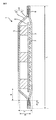
- FIG. 1 is a cross-sectional view schematically showing a cross section of a vapor chamber 1 in one embodiment of the present invention.
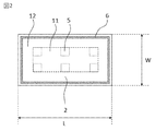
- FIG. 2 is a plan view schematically showing the vapor chamber 1 according to one embodiment of the present invention as viewed from the first sheet side.
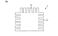
- FIG. 3 is a cross-sectional view schematically showing a cross section of a convex portion having a fine structure in one embodiment.
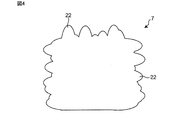
- FIG. 4 is a cross-sectional view schematically showing a cross section of a convex portion having a fine structure according to another embodiment.
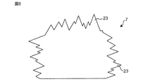
- FIG. 5 is a cross-sectional view schematically showing a cross section of a convex portion having a fine structure according to another embodiment.
- FIG. 6 is a cross-sectional view schematically showing a cross section of a convex portion having a fine structure according to another embodiment.
- the vapor chamber 1 of the present embodiment includes a housing 4 composed of a first sheet 2 and a second sheet 3 facing each other, and a working fluid sealed in the casing (FIG. 1). Not shown).
- a plurality of pillars 5 are provided between the first sheet 2 and the second sheet 3 to support them from the inside.
- the first sheet 2 and the second sheet 3 are supported by the pillar 5 in the inner region 11 (hereinafter also referred to as “central region”) connecting the pillars 5 existing on the edge side, and are separated by a predetermined distance. .
- the first sheet 2 and the second sheet 3 are close to each other in the region 12 outside the central region 11 (hereinafter, also referred to as “terminal region”), contact at the outer edge portion, and are bonded and sealed.
- the portion 6 where the first sheet and the second sheet are joined is also referred to as a “joint portion”.
- the first sheet 2 and the second sheet 3 typically begin to approach each other from the end of the column 5 closest to the edge of the sheet and are joined to each other at the joint 6 located at the outer edge of the sheet. Is sealed.
- seat 3 has the some convex part 7 in the inner surface (namely, main surface by the side of the internal space of a housing
- a wick 8 is provided on the second sheet 3. That is, in the vapor chamber 1 of the present embodiment, the wick 8 is positioned on the second sheet 3, the column 5 is positioned on the wick 8, and the first sheet 2 is positioned on the column 5.
- the casing 4 includes a first sheet 2 and a second sheet 3 that face each other.
- the size of the casing 4 (that is, the vapor chamber) is not particularly limited.
- the thickness of the housing 4 (indicated by T in FIG. 1) is preferably 100 ⁇ m or more and 600 ⁇ m or less, more preferably 200 ⁇ m or more and 500 ⁇ m or less.
- the length (indicated by L in FIG. 1) and the width (indicated by W in FIG. 2) of the housing 4 can be appropriately set according to the application to be used, for example, 5 mm to 500 mm, 20 mm or more. It may be 300 mm or less, or 50 mm or more and 200 mm or less.
- the shape of the casing 4 is not particularly limited.
- the planar shape of the housing 4 (the shape shown in FIG. 2, that is, the shape seen from the upper side in FIG. 1) is a polygon such as a triangle or a rectangle, a circle, an ellipse, a combination of these, etc. It can be.
- the material for forming the first sheet 2 and the second sheet 3 is not particularly limited as long as it has characteristics suitable for use as a vapor chamber, such as thermal conductivity, strength, flexibility, and the like.
- the material constituting the first sheet 2 and the second sheet 3 is preferably a metal, such as copper, nickel, aluminum, magnesium, titanium, iron, or an alloy containing them as a main component, particularly preferably. It can be copper.
- the materials constituting the first sheet 2 and the second sheet 3 may be the same or different, but are preferably the same.
- the thickness (indicated by t in FIG. 1) of the first sheet 2 and the second sheet 3 is not particularly limited, but is preferably 10 ⁇ m to 200 ⁇ m, more preferably 30 ⁇ m to 100 ⁇ m, for example, preferably 40 ⁇ m to 60 ⁇ m. It can be:
- the thickness of the first sheet 2 and the second sheet 3 may be the same or different.
- seat 3 may be the same over the whole, and one part may be thin.
- seat 3 is the same.
- the thickness of each sheet of the first sheet 2 and the second sheet 3 is the same throughout.
- the second sheet 3 has a plurality of convex portions 7 on the main surface on the inner space side.
- the hydraulic fluid can be held between the convex portions, and the transmittance of the vapor chamber of the present invention can be increased.
- the transmittance By increasing the transmittance, the heat transport capability of the vapor chamber is improved.
- the convex portion refers to a portion having a relatively higher height than the surroundings, and in addition to the portion protruding from the main surface, the height is relatively high due to a concave portion formed on the main surface, such as a groove. The part which becomes.
- the height of the convex portion 7 is not particularly limited, but may be preferably 1 ⁇ m or more and 100 ⁇ m or less, more preferably 5 ⁇ m or more and 50 ⁇ m or less, and further preferably 15 ⁇ m or more and 30 ⁇ m or less.
- the distance between the convex portions 7 is not particularly limited, but may be preferably 1 ⁇ m or more and 500 ⁇ m or less, more preferably 5 ⁇ m or more and 300 ⁇ m or less, and further preferably 15 ⁇ m or more and 150 ⁇ m or less.
- the capillary force can be further increased.
- the transmittance can be further increased by increasing the distance between the convex portions.
- the shape of the convex portion 7 is not particularly limited, but may be a cylindrical shape, a prism shape, a truncated cone shape, a truncated pyramid shape, or the like. Further, the shape of the convex portion 7 may be a wall shape, that is, a shape in which a groove is formed between adjacent convex portions.
- the convex portion 7 may be formed integrally with the first sheet 2 or the second sheet 3, and is manufactured separately from the first sheet 2 or the second sheet 3, and then fixed at a predetermined position. May be.
- the convex portion 7 is not an essential component and may not exist.
- At least one or both of the first sheet 2 and the second sheet 3 have the convex portion 7, and the convex portion 7 has a fine structure on the surface thereof. Since the convex part 7 has a fine structure on its surface, a capillary force acts on the surface of the convex part 7 and can transport the hydraulic fluid. That is, the convex part 7 itself functions as a wick. Thereby, the heat transport capability of the vapor chamber is improved.
- the convex portion 7 can function as a wick itself, the vapor chamber of this aspect does not require a wick other than the convex portion. Therefore, the present invention provides a vapor chamber that has a convex portion 7 having a fine structure that functions as a wick on the surface and does not have a wick other than the convex portion 7.
- the “fine structure” is a structure in which a plurality of convex shapes and / or concave shapes exist at a predetermined interval, and the height of the convex shape and the depth of the concave shape are 10 nm or more and 10,000 nm or less. And the width of the convex shape and the concave shape is 10 nm or more and 10,000 nm or less.
- the convex shape means a shape having a plurality of protrusions
- the concave shape means a shape having a plurality of dents
- the plurality of protrusions and the plurality of dents may be the same shape. The shape may be different.
- the microstructure may be, for example, a shape in which a plurality of columnar or prismatic columns are arranged, a shape in which a plurality of grooves are formed, a shape in which a plurality of semicircular or semi-elliptical protrusions are formed, and the like. Further, the fine structure may have a regular shape or an irregular shape.
- the convex part having a fine structure for example, as shown in FIG. 3, there can be mentioned one having a plurality of columnar protrusions 21 formed on the surface of the convex part.
- the height, thickness, interval, direction, and the like of the columnar protrusions 21 may be the same or different.
- the convex portion having such a fine structure can be formed by fine processing such as laser processing.
- the convex portion having a fine structure As another example of the convex portion having a fine structure, as shown in FIG. 4, there can be mentioned a case where a plurality of round mountain-like (ball head-like) protrusions 22 are formed on the surface of the convex portion.
- the height, thickness, interval, direction, and the like of the round mountain-like protrusions 22 may be the same or different.
- the convex part having such a fine structure can be obtained, for example, by forming a convex part having a smooth surface and then immersing it in an etching solution.
- the convex part having a fine structure As another example of the convex part having a fine structure, as shown in FIG. 5, there can be mentioned one in which a plurality of needle-shaped (conical) projections 23 are formed.
- the height, thickness, taper angle, interval, direction, and the like of the needle-like projections 23 may be the same or different.
- the convex portion having such a fine structure can be obtained, for example, by forming a convex portion having a smooth surface and then immersing in an etching solution or plating. When etching is used, needle-like projections 23 having a relatively large size and shape can be obtained. Further, when plating is used, a needle-like needle-like projection 23 that is thinner, for example, has a small taper angle, can be obtained.
- the convex portion having a fine structure As another example of the convex portion having a fine structure, as shown in FIG. 6, there may be mentioned one having a plurality of dents 24 formed on the surface of the convex portion.
- the shape such as the depth and width of the recess 24 may be the same or different.
- the convex portion having such a fine structure can be obtained, for example, by forming a convex portion having a smooth surface and then performing a physical treatment such as sandblasting.
- the first sheet 2 and the second sheet 3 are joined to each other at their outer edge portions.
- the joining method is not particularly limited.
- laser welding, resistance welding, diffusion joining, brazing, TIG welding (tungsten-inert gas welding), ultrasonic joining, or resin sealing can be used.
- Laser welding, resistance welding or brazing can be used.
- the pillar 5 supports the first sheet 2 and the second sheet 3 from the inside so that the distance between the first sheet and the second sheet is a predetermined distance.
- the pillar 5 may be in direct contact with each sheet, or may be supported via another member such as a wick.
- the material which forms the said pillar 5 is not specifically limited, For example, it is a metal, for example, they are copper, nickel, aluminum, magnesium, titanium, iron, or an alloy which has them as a main component, Especially preferably, it is copper. obtain.
- the material forming the pillar is the same material as either or both of the first sheet and the second sheet.
- the height of the pillar 5 is larger than the height of the convex portion 7.
- the height of the column 5 is preferably 1.5 times to 100 times, more preferably 2 times to 50 times, and even more preferably 3 times to 20 times the height of the convex portion 7. It can be not more than twice, and more preferably not less than 3 times and not more than 10 times.
- the height of the pillar 5 can be appropriately set according to the desired thickness of the vapor chamber, preferably 50 ⁇ m or more and 500 ⁇ m or less, more preferably 100 ⁇ m or more and 400 ⁇ m or less, and further preferably 100 ⁇ m or more and 200 ⁇ m or less, for example 125 ⁇ m or more. 150 ⁇ m or less.
- the height of the column means the height in the thickness direction of the vapor chamber (the height in the vertical direction in FIG. 1).
- the height of the column 5 may be the same or different in one vapor chamber.
- the height of the pillar 5 in a certain area may be different from the height of the pillar 5 in another area.
- the thickness of the vapor chamber can be partially changed.
- the shape of the column 5 is not particularly limited, but may be a columnar shape, a prismatic shape, a truncated cone shape, a truncated pyramid shape, or the like.
- the thickness of the column 5 is not particularly limited as long as it gives strength capable of suppressing deformation of the casing of the vapor chamber.
- the equivalent circle diameter of a cross section perpendicular to the column height direction is 100 ⁇ m or more and 2000 ⁇ m or less.
- the thickness may be preferably 300 ⁇ m or more and 1000 ⁇ m or less.
- the arrangement of the pillars 5 is not particularly limited, but is preferably arranged evenly, for example, in the form of lattice points so that the distance between the pillars is constant. By arranging the columns evenly, a uniform strength can be ensured throughout the vapor chamber.
- the number and interval of the pillars 5 are not particularly limited, but are preferably 0.125 or more and 0.5 or less, more preferably 0.125 or more, more preferably 1 or less per 1 mm 2 of the main surface area of one sheet that defines the internal space of the vapor chamber. It may be 0.2 or more and 0.3 or less.
- the pillar 5 may be formed integrally with the first sheet, or may be manufactured separately from the first sheet and then fixed to a predetermined portion of the first sheet.
- the wick 8 is not particularly limited as long as it has a structure capable of moving the hydraulic fluid by capillary force.
- the capillary structure that exhibits the capillary force for moving the working fluid is not particularly limited, and may be a known structure used in a conventional vapor chamber.
- examples of the capillary structure include fine structures having irregularities such as pores, grooves, and protrusions, such as a fiber structure, a groove structure, and a network structure.
- the thickness of the wick 8 is not particularly limited, but may be, for example, 5 ⁇ m to 200 ⁇ m, preferably 10 ⁇ m to 80 ⁇ m, and more preferably 30 ⁇ m to 50 ⁇ m.
- the size and shape of the wick 8 are not particularly limited.
- the wick 8 has a size and shape that can be continuously installed from the evaporation section to the condensation section inside the housing.
- the number of wicks is one, but the number of wicks is not limited to this, and a plurality of, for example, two, three, four, five, or more may be used.
- the wick 8 is not an essential component and may not exist.
- irregularities, grooves, or the like may be formed on the surface of one or both of the first sheet and the second sheet, and the sheet itself may function as a wick.
- the pillar 5 can directly contact both the first sheet and the second sheet.
- the hydraulic fluid is not particularly limited as long as it can cause a gas-liquid phase change under the environment in the casing, and for example, water, alcohols, alternative chlorofluorocarbon, or the like can be used.
- the hydraulic fluid is an aqueous compound, preferably water.
- the first sheet 2, the second sheet 3, the pillar 5, and the wick 8 described above are stacked in the order of the second sheet 3, the wick 8, the pillar 5, and the first sheet 2. It is in the state that was done.
- the first sheet 2 and the second sheet 3 approach in the end region 12 as they approach the edge of the sheet, contact at the outer edge, and are joined and sealed.
- the portion where the first sheet and the second sheet are joined is also referred to as a “joint portion”.
- At least one of the first sheet and the second sheet is deformed (curved or refracted) in the terminal region to approach the other sheet, but is 90 ° or less, preferably 100 ° or less, more preferably 110 ° or less. Does not deform at an angle.
- the distance (mm) from the outer edge of the outermost column to the inner edge of the joint between the first sheet and the second sheet is “a”, and the first sheet at the outer edge of the outermost column is When the distance (mm) between the second sheets is “b”, the following formula 1 is satisfied.
- the “outermost column” means the column closest to the joint between the first sheet and the second sheet.
- the vapor chamber of the present invention satisfies the following formula 1 ′.
- Formula 1 ′ 0.06 ⁇ b / a ⁇ 0.1
- the width of the joint (indicated by “c” in FIG. 1) may be preferably 1 mm or less, more preferably 0.8 mm or less, and even more preferably 0.7 mm or less.
- variety of a junction part becomes like this.
- it is 0.02 mm or more, More preferably, it is 0.1 mm or more, More preferably, it may be 0.2 mm or more.
- the distance between the first sheet and the second sheet at a position where the sheet adjacent to the joint between the first sheet and the second sheet starts to deform is preferably 0.06 mm or more, more preferably 0. It may be 1 mm or more, more preferably 0.2 mm or more. That is, b can be preferably 0.06 or more, more preferably 0.1 or more. Further, the distance between the first sheet and the second sheet at the outer edge of the outermost column is preferably 1 mm or less, more preferably 0.8 mm or less, and even more preferably 0.4 mm or less.
- the “outer edge of the outermost column” may be the boundary between the central region 11 and the end region 12. “Distance (mm) from the outer edge of the outermost column to the inner edge of the joint between the first sheet and the second sheet” means the distance between the inner edge of the joint and the column closest to the joint. .
- the “distance (mm) between the first sheet and the second sheet at the outer edge of the outermost column” is the inner main surface of the first sheet and the inner main surface of the second sheet at the outer edge of the outermost column. Means the distance between. Moreover, when a convex part or a recessed part exists in an inner side main surface, the distance between the inner main surfaces of a 1st sheet and a 2nd sheet is based on the surface at the time of assuming that this convex part or a recessed part does not exist.
- the height direction position (position in the vertical direction in FIG. 1) where the joint portion 6 of the first sheet and the second sheet exists is the height (first position) between the first sheet and the second sheet in the central region 11. As long as it is the same height as the sheet or the second sheet).
- the position in the height direction where the joint portion 6 exists is an intermediate portion between the first sheet and the second sheet, that is, the height direction from the joint portion to the inner main surface of the first sheet in the central region 11. The distance and the distance in the height direction from the joint portion to the inner main surface of the second sheet in the central region 11 are equal.
- the vapor chamber of this invention was demonstrated by the said embodiment, the vapor chamber of this invention is not limited to the aspect shown in figure, Various modifications are possible.
- the vapor chamber in another aspect may further have a convex portion on the inner main surface of the first sheet 2.
- a concave portion may be present instead of the convex portion on one or both inner main surfaces of the first sheet 2 or the second sheet 3.
- the vapor chamber in another aspect may further have a wick on the first sheet 2.
- the pillar 5 may support the first sheet 2 via the wick without directly contacting the first sheet 2.
- the vapor chamber of the present invention has a high heat transport capability and a high thermal diffusion capability as described above, it is preferably used for a heat dissipation device.
- the present invention also provides a heat dissipation device comprising the vapor chamber of the present invention.
- the vapor chamber of the present invention is advantageous for downsizing (particularly thinning), and is suitable for use in equipment that requires downsizing, such as electronic equipment.
- the present invention also provides an electronic apparatus comprising the vapor chamber of the present invention or the heat dissipation device of the present invention.
- Example 1 A Cu sheet having a size of 60 mm ⁇ 110 mm was prepared as the first sheet.
- a column was formed by etching.
- the columns were placed in the central region at 1.3 mm intervals.
- the thickness t of the first sheet was 0.05 mm.
- a 60 mm ⁇ 110 mm Cu sheet was prepared.
- a convex portion was formed by etching.
- the convex portion was a quadrangular prism having a bottom surface of 0.15 mm ⁇ 0.15 mm and a height of 0.03 mm.
- the convex portions were arranged in the central region at intervals of 0.15 mm.
- the thickness t of the second sheet was 0.05 mm.
- a vapor chamber was prepared according to the following procedure.
- the second sheet, the wick, and the first sheet were laminated in this order from the bottom, and the outer periphery 4 sides were welded by resistance welding to produce a vapor chamber body.
- the pillars formed on the first sheet were disposed inward, and the convex portions formed on the second sheet were disposed inward.
- a Cu pipe was inserted therein, and the vapor chamber main body and the Cu pipe were fixed with solder.
- This Cu pipe was connected to a syringe containing a vacuum pump and working fluid via a switching valve.
- the switching valve was connected to the inside of the vapor chamber and the vacuum pump, and the inside of the vapor chamber body was depressurized. Thereafter, the valve was switched, the inside of the vapor chamber was connected to the syringe containing the working fluid, and after a predetermined amount of working fluid was injected into the vapor chamber, the Cu pipe was caulked and sealed to obtain the vapor chamber of Example 1. .
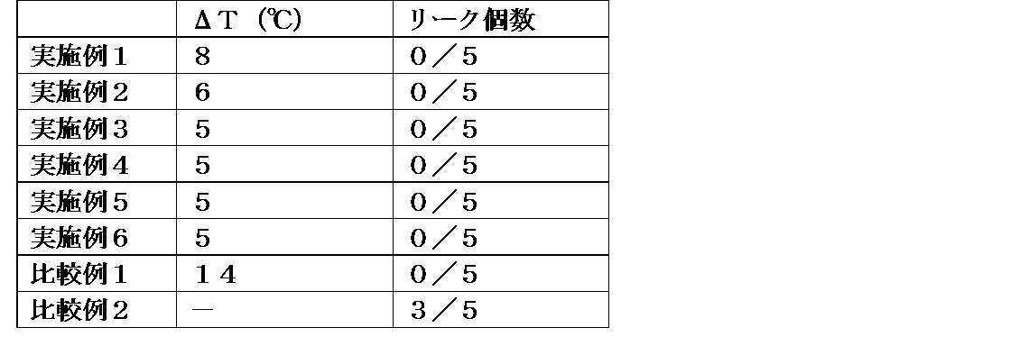
- Examples 2-6 and Comparative Examples 1-2 The vapor chambers of Examples 2 to 6 and Comparative Examples 1 to 2 were manufactured in the same manner as Example 1 except that a, b, and c were values shown in the following table.
- the temperature difference characteristics are as follows. For 5 vapor chambers, when a 15 mm x 15 mm ceramic heater is installed at the center of one short side of the vapor chamber and 10 mm inside from the end, and 3 W of heat is applied, the ceramic heater The temperature of the vapor chamber on the surface opposite to the surface on which was installed was compared with the temperature difference ( ⁇ T (° C.)) of the vapor chamber 10 mm inside from the other short side edge. The average value of ⁇ T is shown in Table 2.
- the vapor chamber of the present invention Since the vapor chamber of the present invention has high reliability, it can be used for a wide range of applications. In particular, it can be used as a cooling device for electronic devices or the like in applications where small and efficient heat transport is required.
Landscapes
- Engineering & Computer Science (AREA)
- Life Sciences & Earth Sciences (AREA)
- Sustainable Development (AREA)
- Physics & Mathematics (AREA)
- Thermal Sciences (AREA)
- Mechanical Engineering (AREA)
- General Engineering & Computer Science (AREA)
- Cooling Or The Like Of Semiconductors Or Solid State Devices (AREA)
- Cooling Or The Like Of Electrical Apparatus (AREA)
- Physical Or Chemical Processes And Apparatus (AREA)
Abstract
本発明のベーパーチャンバー(1)は、外縁部が接合された対向する第1シート(2)および第2シート(3)から成る筐体(4)と、前記第1シートおよび第2シートの間にこれらを内側から支持するように設けられた柱(5)と、前記筐体内に封入された作動液とを有し、前記第1シート(2)および第2シート(3)は、接合部(6)と、接合部(6)から最も近い前記柱(5)間において、角度が90°以下である角部を有しておらず、下記式1を満たす。 式1:0.02≦b/a≦0.3 [式中:aは、最外の柱の外縁から第1シートと第2シートの接合部の内縁までの距離(mm)であり、bは、前記最外の柱の外縁における、第1シートと第2シート間の距離(mm)である。]
Description
本発明は、ベーパーチャンバーに関する。
近年、素子の高集積化、高性能化による発熱量が増加している。また、製品の小型化が進むことで、発熱密度が増加するため、放熱対策が重要となってきた。この状況はスマートフォンやタブレットなどのモバイル端末の分野において特に顕著である。近年、熱対策部材としては、グラファイトシートなどが用いられることが多いが、その熱輸送量は十分ではないため、様々な熱対策部材の使用が検討されている。なかでも、非常に効果的に熱を輸送することが可能であるとして、面状のヒートパイプであるベーパーチャンバーの使用の検討が進んでいる。
ベーパーチャンバーは、筐体の内部に、毛細管力によって作動液を輸送するウィックが設けられ、作動液が封入された構造を有する。上記作動液は、発熱素子からの熱を吸収する蒸発部において発熱素子からの熱を吸収し、ベーパーチャンバー内で蒸発し、凝縮部に移動し、冷却されて液相に戻る。液相に戻った作動液は、ウィックの毛細管力によって再び発熱素子側(蒸発部)に移動し、発熱素子を冷却する。これを繰り返すことにより、ベーパーチャンバーは外部動力を有することなく自立的に作動し、作動液の蒸発潜熱および凝縮潜熱を利用して、二次元的に高速で熱を拡散することができる。
ベーパーチャンバーとして、特許文献1には、対向する2枚の板状体により空洞部を有する凸部が中央部に形成された筐体と、当該空洞部に封入された作動液とを有し、前記空洞部にウィック構造が備えられ、前記凸部の外周部がレーザー溶接にて封止されたベーパーチャンバーが開示されている。また、特許文献2には、エッチング加工された金属シートを2枚以上積み重ねて、少なくとも外周部の一部が接合により密閉された容器を形成したことを特徴とするベーパーチャンバーであって、上記容器の外周部が、上記金属シートの側壁を拡散接合して形成され、側壁の幅が0.3mm以上であることを特徴とするベーパーチャンバーが開示されている。
特許文献1および2に記載のベーパーチャンバーは、筐体の内部空間を形成するために、筐体を構成する金属シートを予め凸状に形成する、あるいは、シートに溝を形成する等の前加工が必要となる。本発明者らは、このような筐体の内部空間を形成するための金属シートの前加工を行わず、筐体を構成する2枚のシートの間に柱を設けることにより、筐体の内部空間を確保することを試みた。しかしながら、このようにして得られたベーパーチャンバーは、信頼性に劣る場合があることがわかった。
本発明は、信頼性の高い、2枚のシートの間に柱を設けた筐体を用いたベーパーチャンバーを提供することを目的とする。
本発明者らは、上記の2枚のシートの間に柱を設けた筐体を用いたベーパーチャンバーの信頼性を高めるために鋭意検討した結果、接合部近傍における2枚のシート間の角度を調整することにより、信頼性の高いベーパーチャンバーを得ることができることを見出し、本発明に至った。
本発明の第1の要旨によれば、
外縁部が接合された対向する第1シートおよび第2シートから成る筐体と、
前記第1シートおよび第2シートの間にこれらを内側から支持するように設けられた柱と、
前記筐体内に封入された作動液とを有し、
前記第1シートおよび第2シートは、接合部と、接合部から最も近い前記柱間において、角度が90°以下である角部を有しておらず、
下記式1を満たす、ベーパーチャンバー
式1: 0.02≦b/a≦0.3
[式中:
aは、最外の柱の外縁から第1シートと第2シートの接合部の内縁までの距離(mm)であり、
bは、前記最外の柱の外縁における、第1シートと第2シート間の距離(mm)である。]
が提供される。
外縁部が接合された対向する第1シートおよび第2シートから成る筐体と、
前記第1シートおよび第2シートの間にこれらを内側から支持するように設けられた柱と、
前記筐体内に封入された作動液とを有し、
前記第1シートおよび第2シートは、接合部と、接合部から最も近い前記柱間において、角度が90°以下である角部を有しておらず、
下記式1を満たす、ベーパーチャンバー
式1: 0.02≦b/a≦0.3
[式中:
aは、最外の柱の外縁から第1シートと第2シートの接合部の内縁までの距離(mm)であり、
bは、前記最外の柱の外縁における、第1シートと第2シート間の距離(mm)である。]
が提供される。
本発明の第2の要旨によれば、上記のベーパーチャンバーを有して成る放熱デバイスが提供される。
本発明の第3の要旨によれば、上記のベーパーチャンバーまたは上記放熱デバイスを有して成る電子機器が提供される。
本発明によれば、上記の2枚のシートの間に柱を設けた筐体を用いたベーパーチャンバーにおいて、接合部近傍における2枚のシート間の角度を調整することにより、具体的には、接合部の内部側の端と接合部から最も近い柱間の距離、および、接合部から最も近い柱が存在する位置における、第1シートと第2シート間の距離の関係を調整することにより、ベーパーチャンバーの信頼性を高めることができる。また、本発明の構成とすることにより、信頼性の高いベーパーチャンバーを容易に製造することができる。
以下、本発明のベーパーチャンバーについて、図面を参照しながら詳細に説明する。
図1および図2に示されるように、本実施形態のベーパーチャンバー1は、対向する第1シート2および第2シート3から構成される筐体4と、その内部に封入された作動液(図示していない)を有して成る。上記筐体4において内部空間を確保するために、第1シート2および第2シート3の間には、これらを内側から支持する複数の柱5が設けられている。第1シート2および第2シート3は、縁側に存在する柱5を結んだ内側の領域11(以下、「中央領域」ともいう)において、柱5により支持され、所定の距離で離隔している。第1シート2および第2シート3は、中央領域11の外側の領域12(以下、「末端領域」ともいう)において、互いに接近し、外縁部において接触し、接合され、封止されている。第1シートおよび第2シートが接合されている部分6を、以下、「接合部」とも称する。換言すれば、上記第1シート2および第2シート3は、典型的にはシートの縁から最も近い柱5の端から互いに接近し始め、シートの外縁部に位置する接合部6において互いに接合され、封止されている。第2シート3は、その内側表面(即ち、筐体の内部空間側の主面)に、複数の凸部7を有する。第2シート3上には、ウィック8が設けられている。即ち、本実施形態のベーパーチャンバー1においては、第2シート3上にウィック8が位置し、ウィック8上に柱5が位置し、柱5上に第1シート2が位置している。
上記筐体4は、対向する第1シート2および第2シート3から構成される。
上記筐体4(即ち、ベーパーチャンバー)の大きさは、特に限定されない。筐体4の厚さ(図1においてTで示される)は、好ましくは100μm以上600μm以下であり、より好ましくは200μm以上500μm以下であり得る。筐体4の長さ(図1においてLで示される)および幅(図2においてWで表される)は、用いる用途に応じて適宜設定することができ、例えば、5mm以上500mm以下、20mm以上300mm以下または50mm以上200mm以下であり得る。
上記筐体4の形状は、特に限定されない。例えば、上記筐体4の平面形状(図2に示される形状、即ち、図1において図面上側から見た形状)は、三角形または矩形等の多角形、円形、楕円形、これらを組み合わせた形状などであり得る。
上記第1シート2および第2シート3を形成する材料は、ベーパーチャンバーとして用いるのに適した特性、例えば熱伝導性、強度、柔軟性等を有するものであれば、特に限定されない。上記第1シート2および第2シート3を構成する材料は、好ましくは金属であり、例えば銅、ニッケル、アルミニウム、マグネシウム、チタン、鉄、またはそれらを主成分とする合金等であり、特に好ましくは銅であり得る。第1シート2および第2シート3を構成する材料は、同じであっても、異なっていてもよいが、好ましくは同じである。
上記第1シート2および第2シート3の厚さ(図1においてtで示される)は、特に限定されないが、好ましくは10μm以上200μm以下、より好ましくは30μm以上100μm以下、例えば好ましくは40μm以上60μm以下であり得る。第1シート2および第2シート3の厚さは、同じであっても異なっていてもよい。また、第1シート2および第2シート3の各シートの厚さは、全体にわたって同じであってもよく、一部が薄くてもよい。一の態様において、第1シート2および第2シート3の厚さは同じである。また、別の態様において、第1シート2および第2シート3の各シートの厚さは全体にわたって同じである。
本実施形態において、第2シート3は、内部空間側の主面に複数の凸部7を有している。シートがかかる複数の凸部を有することにより、凸部間に作動液を保持することができ、本発明のベーパーチャンバーの透過率を上げることが可能になる。透過率を上げることにより、ベーパーチャンバーの熱輸送能力が向上する。ここに、凸部とは、周囲よりも相対的に高さが高い部分をいい、主面から突出した部分に加え、主面に形成された凹部、例えば溝などにより相対的に高さが高くなっている部分も含む。
上記凸部7の高さは、特に限定されないが、好ましくは1μm以上100μm以下、より好ましくは5μm以上50μm以下、さらに好ましくは15μm以上30μm以下であり得る。凸部の高さをより高くすることにより、作動液の保持量をより多くすることができる。また、凸部の高さをより低くすることにより、作動液の蒸気が移動するための空間をより広く確保することができる。従って、凸部の高さを調整することにより、ベーパーチャンバーの熱輸送能力および熱拡散能力を調整することができる。
上記凸部7間の距離は、特に限定されないが、好ましくは1μm以上500μm以下、より好ましくは5μm以上300μm以下、さらに好ましくは15μm以上150μm以下であり得る。凸部間の距離を小さくすることにより、より毛細管力を大きくすることができる。また、凸部間の距離を大きくすることにより、透過率をより高くすることができる。
上記凸部7の形状は、特に限定されないが、円柱形状、角柱形状、円錐台形状、角錐台形状等であり得る。また、上記凸部7の形状は、壁状であってもよく、即ち、隣接する凸部の間に溝が形成されるような形状であってもよい。
上記凸部7は、第1シート2または第2シート3と一体に形成されていてもよく、また、第1シート2または第2シート3と別個に製造し、その後、所定の箇所に固定してもよい。
尚、本発明のベーパーチャンバーにおいて、上記凸部7は必須の構成ではなく、存在してなくてもよい。
一の態様において、上記第1シート2および第2シート3の少なくとも一方または両方は、上記凸部7を有し、かかる凸部7は、その表面に微細構造を有する。凸部7は、その表面に微細構造を有することにより、凸部7の表面に毛細管力が作用し、作動液を輸送することができる。即ち、凸部7自体がウィックとして機能する。これにより、ベーパーチャンバーの熱輸送能が向上する。
上記のように、凸部7はそれ自体ウィックとして機能し得るので、本態様のベーパーチャンバーは、凸部以外のウィックを必要としない。従って、本発明は、表面にウィックとして機能する微細構造を有する凸部7を有し、凸部7以外のウィックを有しないベーパーチャンバーを提供する。
ここに、「微細構造」とは、凸形状および/または凹形状が、所定の間隔で複数存在する構造であって、凸形状の高さおよび凹形状の深さが、10nm以上10,000nm以下であり、凸形状および凹形状の幅が、10nm以上10,000nm以下である構造を意味する。凸形状は、複数の突起が存在する形状を意味し、凹形状は、複数の凹みが存在する形状を意味し、複数の突起および複数の凹みは、それぞれ、同一の形状であってもよいし、異なる形状であってもよい。微細構造は、例えば、円柱状、角柱状の柱が複数並んでいる形状、溝が複数形成された形状、半円形状または半楕円形状の突起が複数形成された形状等であってもよい。また、微細構造は、規則的な形状であってもよく、不規則な形状であってもよい。
微細構造を有する凸部の例としては、例えば図3に示されるように、凸部の表面に柱状突起21が複数形成されたものが挙げられる。かかる柱状突起21の高さ、太さ、間隔、向き等は、同じであってもよく、異なっていてもよい。このような微細構造を有する凸部は、例えばレーザー加工などの微細加工により形成することができる。
微細構造を有する凸部の別の例としては、図4に示されるように、凸部の表面に丸山状(球頭状)突起22が複数形成されたものが挙げられる。かかる丸山状突起22の高さ、太さ、間隔、向き等は、同じであってもよく、異なっていてもよい。このような微細構造を有する凸部は、例えば、表面が滑らかな凸部を形成した後、エッチング液に浸漬することにより得ることができる。
微細構造を有する凸部の別の例としては、図5に示されるように、針山状(錐状)突起23が複数形成されたものが挙げられる。かかる針山状突起23の高さ、太さ、テーパーの角度、間隔、向き等は、同じであってもよく、異なっていてもよい。このような微細構造を有する凸部は、例えば、表面が滑らかな凸部を形成した後、エッチング液に浸漬する、あるいはめっきを施すことにより得ることができる。エッチングを利用する場合には、比較的大きさおよび形状がそろった針山状突起23を得ることができる。また、めっきを利用する場合には、より細い、例えばテーパーの角度が小さな針状の針山状突起23を得ることができる。
微細構造を有する凸部の別の例としては、図6に示されるように、凸部の表面に凹み24が複数形成されたものが挙げられる。かかる凹み24の深さ、幅等の形状は、同じであってもよく、異なっていてもよい。このような微細構造を有する凸部は、例えば、表面が滑らかな凸部を形成した後、サンドブラストのような物理的な処理を行うことにより得ることができる。
上記第1シート2および第2シート3は、これらの外縁部において互いに接合されている。かかる接合の方法は、特に限定されないが、例えばレーザー溶接、抵抗溶接、拡散接合、ロウ接、TIG溶接(タングステン-不活性ガス溶接)、超音波接合または樹脂封止を用いることができ、好ましくはレーザー溶接、抵抗溶接またはロウ接を用いることができる。
上記柱5は、第1シートと第2シート間の距離が所定の距離となるように、第1シート2および第2シート3を内側から支持している。柱5を筐体4の内部に設置することにより、筐体の内部が減圧された場合、筐体外部からの外圧が加えられた場合等に筐体が変形することを抑制することができる。尚、柱が第1シートおよび第2シートを支持する際は、柱が直接各シートに接して支持してもよく、他の部材、例えばウィック等を介して支持してもよい。
上記柱5を形成する材料は、特に限定されないが、例えば金属であり、例えば銅、ニッケル、アルミニウム、マグネシウム、チタン、鉄、またはそれらを主成分とする合金等であり、特に好ましくは銅であり得る。好ましい態様において、柱を形成する材料は、第1シートおよび第2シートのいずれかまたは両方と同じ材料である。
上記柱5の高さは、上記凸部7の高さよりも大きい。一の態様において、上記柱5の高さは、上記凸部7の高さの、好ましくは1.5倍以上100倍以下、より好ましくは2倍以上50倍以下、さらに好ましくは3倍以上20倍以下、さらにより好ましくは3倍以上10倍以下であり得る。
上記柱5の高さは、所望のベーパーチャンバーの厚みに応じて適宜設定することができ、好ましくは50μm以上500μm以下、より好ましくは100μm以上400μm以下、さらに好ましくは100μm以上200μm以下、例えば125μm以上150μm以下である。ここに、柱の高さとは、ベーパーチャンバーの厚み方向の高さ(図1において上下方向の高さ)をいう。
尚、上記柱5の高さは、一のベーパーチャンバーにおいて、同じであっても、異なっていてもよい。例えば、ある領域における柱5の高さと、別の領域における柱5の高さを異なるものとしてもよい。一部の柱5の高さを変更することにより、ベーパーチャンバーの厚さを部分的に変更することができる。
上記柱5の形状は、特に限定されないが、円柱形状、角柱形状、円錐台形状、角錐台形状等であり得る。
上記柱5の太さは、ベーパーチャンバーの筐体の変形を抑制できる強度を与えるものであれば特に限定されないが、例えば柱の高さ方向に垂直な断面の円相当径は、100μm以上2000μm以下、好ましくは300μm以上1000μm以下であり得る。上記柱の円相当径を大きくすることにより、ベーパーチャンバーの筐体の変形をより抑制することができる。また、上記柱の円相当径を小さくすることにより、作動液の蒸気が移動するための空間をより広く確保することができる。
上記柱5の配置は、特に限定されないが、好ましくは均等に、例えば柱間の距離が一定となるように格子点状に配置される。柱を均等に配置することにより、ベーパーチャンバー全体にわたって均一な強度を確保することができる。
上記柱5の数および間隔は、特に限定されないが、ベーパーチャンバーの内部空間を規定する一のシートの主面の面積1mm2あたり、好ましくは0.125本以上0.5本以下、より好ましくは0.2本以上0.3本以下であり得る。上記柱の数を多くすることにより、ベーパーチャンバー(または筐体)の変形をより抑制することができる。また、上記柱の数をより少なくすることにより、作動液の蒸気が移動するための空間をより広く確保することができる。
上記柱5は、第1シートと一体に形成されていてもよく、また、第1シートと別個に製造し、その後、第1シートの所定の箇所に固定してもよい。
上記ウィック8は、毛細管力により作動液を移動させることができる構造を有するものであれば特に限定されない。作動液を移動させる毛細管力を発揮する毛細管構造は、特に限定されず、従来のベーパーチャンバーにおいて用いられている公知の構造であってもよい。例えば、上記毛細管構造は、細孔、溝、突起などの凹凸を有する微細構造、例えば、繊維構造、溝構造、網目構造等が挙げられる。
上記ウィック8の厚みは、特に限定されないが、例えば5μm以上200μm以下、好ましくは10μm以上80μm以下、より好ましくは30μm以上50μm以下であり得る。
上記ウィック8の大きさおよび形状は、特に限定されないが、例えば、筐体の内部において蒸発部から凝縮部まで連続して設置できる大きさおよび形状を有することが好ましい。
本実施形態のベーパーチャンバーでは、ウィックは1枚であるが、これに限定されず、複数枚、例えば2枚、3枚、4枚、5枚またはそれ以上であってもよい。
尚、本発明のベーパーチャンバーにおいて、上記ウィック8は必須の構成ではなく、存在してなくてもよい。この場合、第1シートおよび第2シートのいずれかまたは両方の表面に、凹凸、溝等を形成し、かかるシート自体をウィックとして機能させてもよい。また、ウィックが存在しない箇所においては、上記柱5は、第1シートおよび第2シートの両方に直接接し得る。
上記作動液は、筐体内の環境下において気-液の相変化を生じ得るものであれば特に限定されず、例えば水、アルコール類、代替フロン等を用いることができる。一の態様において、作動液は水性化合物であり、好ましくは水である。
本実施形態のベーパーチャンバー1では、上記で説明した、第1シート2、第2シート3、柱5、ウィック8が、第2シート3、ウィック8、柱5および第1シート2の順で積層された状態にある。第1シート2および第2シート3は、末端領域12において、シートの縁に近づくに従って接近し、外縁部において接触し、接合され、封止されている。第1シートおよび第2シートが接合されている部分を、以下、「接合部」とも称する。第1シートおよび第2シートの少なくとも一方は、末端領域において、他方のシートに接近するために変形(湾曲または屈折)するが、90°以下、好ましくは100°以下、より好ましくは110°以下の角度では変形しない。
本発明のベーパーチャンバーは、最外の柱の外縁から、第1シートと第2シートの接合部の内縁までの距離(mm)を「a」、最外の柱の外縁における、第1シートと第2シート間の距離(mm)を「b」とした場合、下記式1を満たす。ここに、「最外の柱」とは、第1シートと第2シートの接合部から最も近い柱を意味する。
式1: 0.02≦b/a≦0.3
式1: 0.02≦b/a≦0.3
上記の式1を満たすことにより、信頼性の高いベーパーチャンバーを得ることができる。
好ましい態様において、本発明のベーパーチャンバーは、下記式1’を満たす。
式1’: 0.06≦b/a≦0.1
式1’: 0.06≦b/a≦0.1
一の態様において、接合部の幅(図1の「c」で示される)は、好ましくは1mm以下、より好ましくは0.8mm以下、さらにより好ましくは0.7mm以下であり得る。また、接合部の幅は、好ましくは0.02mm以上、より好ましくは0.1mm以上、さらに好ましくは0.2mm以上であり得る。
一の態様において、第1シートと第2シートの接合部に隣接するシートが変形を開始する位置における第1シートと第2シート間の距離は、好ましくは0.06mm以上、より好ましくは0.1mm以上、さらに好ましくは0.2mm以上であり得る。即ち、bは、好ましくは0.06以上、より好ましくは0.1以上であり得る。また、最外の柱の外縁における第1シートと第2シート間の距離は、好ましくは1mm以下、より好ましくは0.8mm以下、さらに好ましくは0.4mm以下であり得る。
ここに、典型的には、「最外の柱の外縁」とは、中央領域11と末端領域12の境界であり得る。「最外の柱の外縁から第1シートと第2シートの接合部の内縁までの距離(mm)」とは、接合部の内部側の端と接合部から最も近い柱間の距離を意味する。
上記「最外の柱の外縁における、第1シートと第2シート間の距離(mm)」とは、最外の柱の外縁における、第1シートの内側主面と第2シートの内側主面間の距離を意味する。また、内側主面に凸部または凹部が存在する場合、第1シートおよび第2シートの内側主面間の距離は、かかる凸部または凹部が存在しないと仮定した場合の面を基準とする。
上記第1シートと第2シートの接合部6が存在する高さ方向の位置(図1において上下方向における位置)は、中央領域11における第1シートおよび第2シートの間の高さ(第1シートまたは第2シートと同じ高さである場合を含む)であれば、特に限定されない。好ましい態様において、接合部6が存在する高さ方向の位置は、第1シートと第2シートの中間部分、即ち、接合部から中央領域11における第1シートの内側主面までの高さ方向の距離と、接合部から中央領域11における第2シートの内側主面までの高さ方向の距離とが等しい。
以上、本発明のベーパーチャンバーについて、上記実施形態により説明したが、本発明のベーパーチャンバーは、図示した態様に限定されず、種々の改変が可能である。
例えば、別の態様におけるベーパーチャンバーは、さらに第1シート2の内側主面上に凸部が存在してもよい。
別の態様におけるベーパーチャンバーは、第1シート2または第2シート3の一方または両方の内側主面上に、凸部の代わりに凹部が存在してもよい。
別の態様におけるベーパーチャンバーは、第1シート2上にさらにウィックを有していてもよい。この場合、柱5は、第1シート2に直接接触せずに、上記ウィックを介して第1シート2を支持してもよい。
本発明のベーパーチャンバーは、上記のように熱輸送能力および熱拡散能力が高いので、放熱デバイスに好適に用いられる。
従って、本発明は、本発明のベーパーチャンバーを有して成る放熱デバイスをも提供する。
本発明のベーパーチャンバーは、小型化(特に薄型化)に有利であり、小型化が要求される機器、例えば電子機器における利用に適している。
従って、本発明は、本発明のベーパーチャンバーまたは本発明の放熱デバイスを有して成る電子機器をも提供する。
実施例1
第1シートとして、60mm×110mmサイズのCu製のシートを準備した。中央領域のサイズは、a=15mmとなるように、26mm×76mmとした。この中央領域には、エッチングにて柱を形成した。柱は、直径0.6mmの円柱形で、第1シートと第2シート間の距離(b)が所定の値(b=0.300mm)となるように調整した。具体的には、柱の高さは0.230mmとした。柱は、1.3mm間隔で中央領域に配置した。第1シートの厚みtは、0.05mmとした。
第1シートとして、60mm×110mmサイズのCu製のシートを準備した。中央領域のサイズは、a=15mmとなるように、26mm×76mmとした。この中央領域には、エッチングにて柱を形成した。柱は、直径0.6mmの円柱形で、第1シートと第2シート間の距離(b)が所定の値(b=0.300mm)となるように調整した。具体的には、柱の高さは0.230mmとした。柱は、1.3mm間隔で中央領域に配置した。第1シートの厚みtは、0.05mmとした。
第2シートとして、60mm×110mmサイズのCu製のシートを準備した。中央領域のサイズは、a=15mmとなるように、26mm×76mmとした。この中央領域には、エッチングにて凸部を形成した。凸部は、底面が0.15mm×0.15mmである四角柱形で、高さ0.03mmとした。凸部は、0.15mm間隔で中央領域に配置した。第2シートの厚みtは、0.05mmとした。
ウィックとして、厚み0.04mmのメッシュを用いた。
作動液として、水を用いた。
上記の第1シート、第2シート、ウィック、作動液を用い、以下の手順でベーパーチャンバーを作製した。
まず、下から第2シート、ウィック、第1シートの順に積層し、外周部4辺を抵抗溶接により溶接し、ベーパーチャンバー本体を作製した。この時、第1シートに形成した柱は内向きに配置し、第2シートに形成した凸部は内向きに配置した。接合部の幅cは、溶接時の電極幅で所定の値(c=0.7mm)に調整した。また、最外の柱の外縁から第1シートと第2シートの接合部の内縁までの距離aが所定の値(a=15mm)となるように接合位置を調整した。積層した第1シートおよび第2シート端から1.3mm内側の所から幅c=0.7mmで溶接を行った。
次に、得られたベーパーチャンバー本体の4角のうちの1角を切り取り、そこにCuパイプを差し込んだあと、ベーパーチャンバー本体とCuパイプをハンダにより固定した。このCuパイプを、切り替えバルブを介して真空ポンプと作動液の入った注射器につないだ。始めに切り替えバルブをベーパーチャンバー内部と真空ポンプをつないだ状態にし、ベーパーチャンバー本体内部を減圧した。その後、バルブを切り替え、ベーパーチャンバー内部と作動液の入った注射器をつなぎ、所定量の作動液をベーパーチャンバー内部に注入した後、Cuパイプをかしめて封止し、実施例1のベーパーチャンバーとした。
実施例2~6および比較例1~2
a、bおよびcが、下記表に示す値となるようにしたこと以外は実施例1と同じようにして、実施例2~6および比較例1~2のベーパーチャンバーを作製した。
a、bおよびcが、下記表に示す値となるようにしたこと以外は実施例1と同じようにして、実施例2~6および比較例1~2のベーパーチャンバーを作製した。

(評価)
・性能試験および信頼性試験
上記で作製したベーパーチャンバーについて、温度差特性を測定することにより性能を評価した。温度差特性は、5個のベーパーチャンバーについて、ベーパーチャンバーの一方の短辺部中央で、かつ端部から10mm内側に15mm×15mmのセラミックヒーターを設置し、3Wの熱量を投入した時に、セラミックヒーターが設置された面の反対側の面のベーパーチャンバーの温度と、もう一方の短辺部端部から10mm内側のベーパーチャンバーの温度差(ΔT(℃))を比較して行った。ΔTの平均値を表2に示す。
・性能試験および信頼性試験
上記で作製したベーパーチャンバーについて、温度差特性を測定することにより性能を評価した。温度差特性は、5個のベーパーチャンバーについて、ベーパーチャンバーの一方の短辺部中央で、かつ端部から10mm内側に15mm×15mmのセラミックヒーターを設置し、3Wの熱量を投入した時に、セラミックヒーターが設置された面の反対側の面のベーパーチャンバーの温度と、もう一方の短辺部端部から10mm内側のベーパーチャンバーの温度差(ΔT(℃))を比較して行った。ΔTの平均値を表2に示す。
・信頼性試験
上記で作製したベーパーチャンバーについて、105℃に100時間放置する高温放置試験により、ベーパーチャンバーの信頼性を評価した。評価は、5個のベーパーチャンバーについて、高温放置前後でリークしているかを外観および第1シートと第2シートを同時に押圧することにより判断した。リークが起こっていれば外観において第1シートと第2シートとの距離が大きくなる。また、同時に押圧すると一方のシートが他方のシート方向へ変形する。少なくともどちらか一方が認められた場合にリークしていると判断した。リーク個数を表2に示す。
上記で作製したベーパーチャンバーについて、105℃に100時間放置する高温放置試験により、ベーパーチャンバーの信頼性を評価した。評価は、5個のベーパーチャンバーについて、高温放置前後でリークしているかを外観および第1シートと第2シートを同時に押圧することにより判断した。リークが起こっていれば外観において第1シートと第2シートとの距離が大きくなる。また、同時に押圧すると一方のシートが他方のシート方向へ変形する。少なくともどちらか一方が認められた場合にリークしていると判断した。リーク個数を表2に示す。
本発明のベーパーチャンバーは、信頼性が高いので、幅広い用途に用いることができる。特に、電子機器等の冷却デバイス等として、小型で効率的な熱輸送が求められる用途に用いることができる。
1 ベーパーチャンバー
2 第1シート
3 第2シート
4 筐体
5 柱
6 接合部
7 凸部
8 ウィック
11 中央領域
12 末端領域
21 柱状突起
22 丸山状突起
23 針山状突起
24 凹み
2 第1シート
3 第2シート
4 筐体
5 柱
6 接合部
7 凸部
8 ウィック
11 中央領域
12 末端領域
21 柱状突起
22 丸山状突起
23 針山状突起
24 凹み
Claims (9)
- 外縁部が接合された対向する第1シートおよび第2シートから成る筐体と、
前記第1シートおよび第2シートの間にこれらを内側から支持するように設けられた柱と、
前記筐体内に封入された作動液とを有し、
前記第1シートおよび第2シートは、接合部と、接合部から最も近い前記柱間において、角度が90°以下である角部を有しておらず、
下記式1を満たす、ベーパーチャンバー。
式1: 0.02≦b/a≦0.3
[式中:
aは、最外の柱の外縁から第1シートと第2シートの接合部の内縁までの距離(mm)であり、
bは、前記最外の柱の外縁における、第1シートと第2シート間の距離(mm)である。] - 第1シートおよび第2シートの厚みが、10μm以上200μm以下である、請求項1に記載のベーパーチャンバー。
- 前記接合部の幅が1.0mm以下である、請求項1または2項に記載のベーパーチャンバー。
- 前記第1シートおよび第2シートが、銅のシートである、請求項1~3のいずれか1項に記載のベーパーチャンバー。
- さらに、ウィックを有する請求項1~4のいずれか1項に記載のベーパーチャンバー。
- 前記第1シートおよび第2シートの少なくとも一方が、その内面の少なくとも一部に凸部を備える、請求項1~5のいずれか1項に記載のベーパーチャンバー。
- 前記凸部が、表面に微細構造が形成された凸部である、請求項6に記載のベーパーチャンバー。
- 請求項1~7のいずれか1項に記載のベーパーチャンバーを有して成る放熱デバイス。
- 請求項1~7のいずれか1項に記載のベーパーチャンバーまたは請求項8に記載の放熱デバイスを有して成る電子機器。
Priority Applications (3)
| Application Number | Priority Date | Filing Date | Title |
|---|---|---|---|
| CN201880005148.0A CN110088556B (zh) | 2017-04-28 | 2018-04-26 | 均热板 |
| JP2019506538A JP6741142B2 (ja) | 2017-04-28 | 2018-04-26 | ベーパーチャンバー |
| US16/414,802 US11150030B2 (en) | 2017-04-28 | 2019-05-17 | Vapor chamber |
Applications Claiming Priority (4)
| Application Number | Priority Date | Filing Date | Title |
|---|---|---|---|
| PCT/JP2017/017035 WO2018198350A1 (ja) | 2017-04-28 | 2017-04-28 | ベーパーチャンバー |
| JPPCT/JP2017/017035 | 2017-04-28 | ||
| JP2017-190718 | 2017-09-29 | ||
| JP2017190718 | 2017-09-29 |
Related Child Applications (1)
| Application Number | Title | Priority Date | Filing Date |
|---|---|---|---|
| US16/414,802 Continuation-In-Part US11150030B2 (en) | 2017-04-28 | 2019-05-17 | Vapor chamber |
Publications (1)
| Publication Number | Publication Date |
|---|---|
| WO2018199215A1 true WO2018199215A1 (ja) | 2018-11-01 |
Family
ID=63919315
Family Applications (1)
| Application Number | Title | Priority Date | Filing Date |
|---|---|---|---|
| PCT/JP2018/016936 Ceased WO2018199215A1 (ja) | 2017-04-28 | 2018-04-26 | ベーパーチャンバー |
Country Status (4)
| Country | Link |
|---|---|
| US (1) | US11150030B2 (ja) |
| JP (1) | JP6741142B2 (ja) |
| CN (1) | CN110088556B (ja) |
| WO (1) | WO2018199215A1 (ja) |
Cited By (4)
| Publication number | Priority date | Publication date | Assignee | Title |
|---|---|---|---|---|
| EP3761353A4 (en) * | 2019-04-18 | 2021-06-09 | Furukawa Electric Co. Ltd. | HEATSINK |
| WO2021157506A1 (ja) * | 2020-02-07 | 2021-08-12 | 株式会社村田製作所 | ベーパーチャンバー |
| US20240017347A1 (en) * | 2019-03-29 | 2024-01-18 | Delta Electronics, Inc. | Heat transmitting device |
| JP2024526071A (ja) * | 2021-06-11 | 2024-07-17 | ケーエムダブリュ・インコーポレーテッド | ベーパーチャンバのウィック部形成方法およびベーパーチャンバの製造方法 |
Families Citing this family (20)
| Publication number | Priority date | Publication date | Assignee | Title |
|---|---|---|---|---|
| US12523431B2 (en) | 2014-09-15 | 2026-01-13 | Kelvin Thermal Technologies, Inc. | Polymer-based microfabricated thermal ground plane |
| US11988453B2 (en) | 2014-09-17 | 2024-05-21 | Kelvin Thermal Technologies, Inc. | Thermal management planes |
| US12385697B2 (en) | 2014-09-17 | 2025-08-12 | Kelvin Thermal Technologies, Inc. | Micropillar-enabled thermal ground plane |
| WO2018208801A1 (en) | 2017-05-08 | 2018-11-15 | Kelvin Thermal Technologies, Inc. | Thermal management planes |
| WO2019049781A1 (ja) * | 2017-09-07 | 2019-03-14 | 株式会社村田製作所 | 回路ブロック集合体 |
| JP6560428B1 (ja) * | 2018-11-30 | 2019-08-14 | 古河電気工業株式会社 | ヒートシンク |
| JP6582114B1 (ja) * | 2018-11-30 | 2019-09-25 | 古河電気工業株式会社 | ヒートシンク |
| DE212019000445U1 (de) * | 2018-12-11 | 2021-08-17 | Kelvin Thermal Technologies | Dampfkammer |
| WO2020235449A1 (ja) * | 2019-05-21 | 2020-11-26 | 株式会社巴川製紙所 | 温調ユニット |
| US12584696B2 (en) * | 2019-12-12 | 2026-03-24 | National Tsing Hua University | Vapor chamber system |
| TWI733272B (zh) * | 2019-12-12 | 2021-07-11 | 國立清華大學 | 均溫板裝置 |
| CN112996339B (zh) * | 2019-12-12 | 2023-09-26 | 王训忠 | 均温板装置 |
| CN111059924A (zh) * | 2019-12-28 | 2020-04-24 | 江西麦克斯韦科技有限公司 | 一种双面椭圆绕流水冷散热器 |
| CN113465428A (zh) * | 2020-03-30 | 2021-10-01 | 超众科技股份有限公司 | 热传导部件和热传导部件的制造方法 |
| CN113473792A (zh) * | 2020-03-30 | 2021-10-01 | 超众科技股份有限公司 | 热传导部件和热传导部件的制造方法 |
| US12464679B2 (en) | 2020-06-19 | 2025-11-04 | Kelvin Thermal Technologies, Inc. | Folding thermal ground plane |
| US12120851B2 (en) * | 2022-04-20 | 2024-10-15 | Microsoft Technology Licensing, Llc | 3-D structured two-phase cooling boilers with nano structured boiling enhancement coating |
| US12189441B2 (en) | 2022-04-20 | 2025-01-07 | Microsoft Technology Licensing, Llc | 3-D structured two-phase microfluidic cooling with nano structured boiling enhancement coating |
| CN117794155A (zh) * | 2022-09-21 | 2024-03-29 | 技嘉科技股份有限公司 | 散热装置 |
| TWI812477B (zh) * | 2022-09-21 | 2023-08-11 | 技嘉科技股份有限公司 | 散熱裝置 |
Citations (6)
| Publication number | Priority date | Publication date | Assignee | Title |
|---|---|---|---|---|
| US5465782A (en) * | 1994-06-13 | 1995-11-14 | Industrial Technology Research Institute | High-efficiency isothermal heat pipe |
| US5642776A (en) * | 1996-02-27 | 1997-07-01 | Thermacore, Inc. | Electrically insulated envelope heat pipe |
| JP3062459U (ja) * | 1999-03-25 | 1999-10-08 | 嘉豪 李 | 超薄板状ヒ―トパイプ |
| JP2007107870A (ja) * | 2005-09-14 | 2007-04-26 | Furukawa Electric Co Ltd:The | 圧接接合式ヒートパイプおよびその製造方法 |
| CN203704739U (zh) * | 2013-11-05 | 2014-07-09 | 苏州聚力电机有限公司 | 异质复合式导热装置 |
| WO2016017471A1 (ja) * | 2014-08-01 | 2016-02-04 | 古河電気工業株式会社 | 平面型ヒートパイプ |
Family Cites Families (13)
| Publication number | Priority date | Publication date | Assignee | Title |
|---|---|---|---|---|
| US3680189A (en) * | 1970-12-09 | 1972-08-01 | Noren Products Inc | Method of forming a heat pipe |
| JP3164518B2 (ja) * | 1995-12-21 | 2001-05-08 | 古河電気工業株式会社 | 平面型ヒートパイプ |
| US6679318B2 (en) * | 2002-01-19 | 2004-01-20 | Allan P Bakke | Light weight rigid flat heat pipe utilizing copper foil container laminated to heat treated aluminum plates for structural stability |
| US20060196640A1 (en) | 2004-12-01 | 2006-09-07 | Convergence Technologies Limited | Vapor chamber with boiling-enhanced multi-wick structure |
| JP4874664B2 (ja) * | 2006-02-08 | 2012-02-15 | 株式会社フジクラ | ヒートパイプ |
| TW200849295A (en) * | 2007-06-15 | 2008-12-16 | Fu-Chia Chang | Super-conducting uniform-temperature heat dissipating module |
| US20090025910A1 (en) * | 2007-07-27 | 2009-01-29 | Paul Hoffman | Vapor chamber structure with improved wick and method for manufacturing the same |
| US20090040726A1 (en) * | 2007-08-09 | 2009-02-12 | Paul Hoffman | Vapor chamber structure and method for manufacturing the same |
| CN201867108U (zh) * | 2010-11-11 | 2011-06-15 | 讯凯国际股份有限公司 | 折叠式均温板 |
| US8857502B2 (en) * | 2011-07-26 | 2014-10-14 | Kunshan Jue-Chung Electronics Co., Ltd. | Vapor chamber having heated protrusion |
| CN104422322B (zh) * | 2013-08-29 | 2016-08-10 | 讯强电子(惠州)有限公司 | 均温板及其制造方法 |
| JP6121854B2 (ja) | 2013-09-18 | 2017-04-26 | 東芝ホームテクノ株式会社 | シート型ヒートパイプまたは携帯情報端末 |
| TWI529364B (zh) * | 2014-07-22 | 2016-04-11 | Ultra - thin temperature plate and its manufacturing method |
-
2018
- 2018-04-26 JP JP2019506538A patent/JP6741142B2/ja active Active
- 2018-04-26 CN CN201880005148.0A patent/CN110088556B/zh active Active
- 2018-04-26 WO PCT/JP2018/016936 patent/WO2018199215A1/ja not_active Ceased
-
2019
- 2019-05-17 US US16/414,802 patent/US11150030B2/en active Active
Patent Citations (6)
| Publication number | Priority date | Publication date | Assignee | Title |
|---|---|---|---|---|
| US5465782A (en) * | 1994-06-13 | 1995-11-14 | Industrial Technology Research Institute | High-efficiency isothermal heat pipe |
| US5642776A (en) * | 1996-02-27 | 1997-07-01 | Thermacore, Inc. | Electrically insulated envelope heat pipe |
| JP3062459U (ja) * | 1999-03-25 | 1999-10-08 | 嘉豪 李 | 超薄板状ヒ―トパイプ |
| JP2007107870A (ja) * | 2005-09-14 | 2007-04-26 | Furukawa Electric Co Ltd:The | 圧接接合式ヒートパイプおよびその製造方法 |
| CN203704739U (zh) * | 2013-11-05 | 2014-07-09 | 苏州聚力电机有限公司 | 异质复合式导热装置 |
| WO2016017471A1 (ja) * | 2014-08-01 | 2016-02-04 | 古河電気工業株式会社 | 平面型ヒートパイプ |
Cited By (5)
| Publication number | Priority date | Publication date | Assignee | Title |
|---|---|---|---|---|
| US20240017347A1 (en) * | 2019-03-29 | 2024-01-18 | Delta Electronics, Inc. | Heat transmitting device |
| US12121988B2 (en) * | 2019-03-29 | 2024-10-22 | Delta Electronics, Inc. | Heat transmitting device |
| EP3761353A4 (en) * | 2019-04-18 | 2021-06-09 | Furukawa Electric Co. Ltd. | HEATSINK |
| WO2021157506A1 (ja) * | 2020-02-07 | 2021-08-12 | 株式会社村田製作所 | ベーパーチャンバー |
| JP2024526071A (ja) * | 2021-06-11 | 2024-07-17 | ケーエムダブリュ・インコーポレーテッド | ベーパーチャンバのウィック部形成方法およびベーパーチャンバの製造方法 |
Also Published As
| Publication number | Publication date |
|---|---|
| US11150030B2 (en) | 2021-10-19 |
| JPWO2018199215A1 (ja) | 2020-01-16 |
| CN110088556A (zh) | 2019-08-02 |
| JP6741142B2 (ja) | 2020-08-19 |
| US20190271511A1 (en) | 2019-09-05 |
| CN110088556B (zh) | 2021-06-25 |
Similar Documents
| Publication | Publication Date | Title |
|---|---|---|
| WO2018199215A1 (ja) | ベーパーチャンバー | |
| CN110476033B (zh) | 均热板 | |
| US11421942B2 (en) | Vapor chamber | |
| US11359869B2 (en) | Vapor chamber | |
| US11340022B2 (en) | Vapor chamber having pillars with decreasing cross-sectional area | |
| CN110476032B (zh) | 均热板 | |
| CN111712681B (zh) | 均热板 | |
| CN110546447A (zh) | 均热板 | |
| JP2018189349A (ja) | ベーパーチャンバー | |
| WO2018198350A1 (ja) | ベーパーチャンバー | |
| US11740029B2 (en) | Vapor chamber | |
| JP6773253B1 (ja) | ベーパーチャンバー | |
| WO2018198360A1 (ja) | ベーパーチャンバー | |
| JP2021143809A (ja) | ベーパーチャンバー及び電子機器 |
Legal Events
| Date | Code | Title | Description |
|---|---|---|---|
| 121 | Ep: the epo has been informed by wipo that ep was designated in this application |
Ref document number: 18792152 Country of ref document: EP Kind code of ref document: A1 |
|
| ENP | Entry into the national phase |
Ref document number: 2019506538 Country of ref document: JP Kind code of ref document: A |
|
| NENP | Non-entry into the national phase |
Ref country code: DE |
|
| 122 | Ep: pct application non-entry in european phase |
Ref document number: 18792152 Country of ref document: EP Kind code of ref document: A1 |