WO2018199076A1 - クリアランス計測装置、クリアランス計測センサ及びクリアランス計測方法 - Google Patents
クリアランス計測装置、クリアランス計測センサ及びクリアランス計測方法 Download PDFInfo
- Publication number
- WO2018199076A1 WO2018199076A1 PCT/JP2018/016574 JP2018016574W WO2018199076A1 WO 2018199076 A1 WO2018199076 A1 WO 2018199076A1 JP 2018016574 W JP2018016574 W JP 2018016574W WO 2018199076 A1 WO2018199076 A1 WO 2018199076A1
- Authority
- WO
- WIPO (PCT)
- Prior art keywords
- light
- unit
- wavelength
- peripheral surface
- clearance
- Prior art date
- Legal status (The legal status is an assumption and is not a legal conclusion. Google has not performed a legal analysis and makes no representation as to the accuracy of the status listed.)
- Ceased
Links
Images

Classifications
-
- G—PHYSICS
- G01—MEASURING; TESTING
- G01B—MEASURING LENGTH, THICKNESS OR SIMILAR LINEAR DIMENSIONS; MEASURING ANGLES; MEASURING AREAS; MEASURING IRREGULARITIES OF SURFACES OR CONTOURS
- G01B11/00—Measuring arrangements characterised by the use of optical techniques
- G01B11/14—Measuring arrangements characterised by the use of optical techniques for measuring distance or clearance between spaced objects or spaced apertures
-
- F—MECHANICAL ENGINEERING; LIGHTING; HEATING; WEAPONS; BLASTING
- F01—MACHINES OR ENGINES IN GENERAL; ENGINE PLANTS IN GENERAL; STEAM ENGINES
- F01D—NON-POSITIVE DISPLACEMENT MACHINES OR ENGINES, e.g. STEAM TURBINES
- F01D25/00—Component parts, details, or accessories, not provided for in, or of interest apart from, other groups
-
- F—MECHANICAL ENGINEERING; LIGHTING; HEATING; WEAPONS; BLASTING
- F02—COMBUSTION ENGINES; HOT-GAS OR COMBUSTION-PRODUCT ENGINE PLANTS
- F02C—GAS-TURBINE PLANTS; AIR INTAKES FOR JET-PROPULSION PLANTS; CONTROLLING FUEL SUPPLY IN AIR-BREATHING JET-PROPULSION PLANTS
- F02C7/00—Features, components parts, details or accessories, not provided for in, or of interest apart form groups F02C1/00 - F02C6/00; Air intakes for jet-propulsion plants
-
- G—PHYSICS
- G01—MEASURING; TESTING
- G01B—MEASURING LENGTH, THICKNESS OR SIMILAR LINEAR DIMENSIONS; MEASURING ANGLES; MEASURING AREAS; MEASURING IRREGULARITIES OF SURFACES OR CONTOURS
- G01B11/00—Measuring arrangements characterised by the use of optical techniques
- G01B11/02—Measuring arrangements characterised by the use of optical techniques for measuring length, width or thickness
- G01B11/026—Measuring arrangements characterised by the use of optical techniques for measuring length, width or thickness by measuring distance between sensor and object
Definitions
- the present disclosure can be used for a clearance measuring device for measuring a clearance formed between an inner peripheral surface of a casing having a cylindrical shape and an outer peripheral surface of a rotating body rotating in the casing, and the clearance measuring device.
- the present invention relates to a clearance measurement sensor and a clearance measurement method that can be performed by the clearance measurement device.
- Rotating machines such as a steam turbine, a gas turbine, or a turbocharger in which a rotating body rotates in a casing are known.
- a predetermined clearance is set between the inner peripheral surface of the casing and the outer peripheral surface of the rotating body that rotates in the casing, and it is important to maintain a proper clearance value in order to exhibit appropriate performance. Has been.
- Patent Document 1 discloses that a tip clearance between a moving blade provided in a rotor and a casing is measured using a non-contact sensor in a compressor which is a rotating machine.
- an optical sensor is used as a non-contact sensor for measuring the clearance as in Patent Document 1.
- a marker having a reflectance different from that of the outer peripheral surface is installed on the outer peripheral surface of the moving blade, the laser light irradiated from the optical fiber of the optical sensor is irradiated to the outer peripheral surface of the moving blade, and the marker is based on the change in the amount of reflected light. Is detected to have passed the predetermined position. And the passage time which passes between two predetermined positions from which a marker differs is calculated
- the clearance is calculated based on the reflected light from the marker installed on the outer peripheral surface of the moving blade.
- Reflected light from the marker includes specularly reflected light and scattered light, but if the surface properties in the vicinity of the marker irradiated with light change, especially the scattered light changes, the measurement result becomes unstable, and measurement errors are reduced. It is an inviting factor.
- At least one embodiment of the present invention has been made in view of the above circumstances, and provides a clearance measuring device, a clearance measuring sensor, and a clearance measuring method capable of accurately and stably performing clearance measurement in a rotating machine. For the purpose.
- a clearance measuring device is provided between an inner peripheral surface of a casing having a cylindrical shape and an outer peripheral surface of a rotating body that rotates in the casing.
- a clearance measuring device for measuring a clearance formed on the casing, the first irradiating unit being fixed to the casing and emitting light having a first wavelength toward the outer peripheral surface of the rotating body, and the casing A second irradiating unit that emits light having a second wavelength different from the first wavelength toward the outer peripheral surface of the rotating body; and an irradiation light of the first irradiating unit from the outer peripheral surface of the rotating body.
- the first light receiving unit that receives the corresponding reflected light
- the second light receiving unit that receives the reflected light corresponding to the irradiation light of the second irradiation unit from the outer peripheral surface of the rotating body
- the reflected light is reflected by the first A first receiving unit that receives a first filter unit having a transmission band corresponding to the length, and a second filter unit that has a transmission band corresponding to the second wavelength for the reflected light received by the second light receiving unit
- a time difference in detection timing of the rotating body in the first light receiving unit and the second light receiving unit based on reception results of the second receiving unit and the first receiving unit and the second receiving unit.
- a measuring unit that measures the clearance based on the above.
- the first irradiation unit and the second irradiation unit irradiate light having the first wavelength and the second wavelength toward the outer peripheral surface of the rotating body, respectively, and the outer peripheral surface of the rotating body. Reflected light is received by the first light receiving unit and the second light receiving unit.
- the first light receiving unit receives reflected light corresponding to the irradiation light of the first irradiation unit, and transmits the reflected light to the first receiving unit via the first filter unit, thereby removing the second wavelength component contained in the reflected light.
- the second light receiving unit receives reflected light corresponding to the irradiation light of the second irradiating unit, and transmits the reflected light to the second receiving unit via the second filter unit, thereby removing the first wavelength component included in the reflected light. .
- the result which removed the unnecessary wavelength component contained in reflected light in the 1st light receiving part and the 2nd light receiving part is obtained.
- accurate and stable clearance measurement can be performed regardless of the properties of the outer peripheral surface of the rotating body.
- the first light receiving unit and the second light receiving unit are configured such that the inner surfaces of the isolation walls whose optical axes isolate the internal space of the casing from the outside.
- the first light-receiving unit is arranged so as to be able to receive specularly reflected light from the outer peripheral surface by the light emitted from the first irradiation unit, and the second light-receiving unit is The regular reflection light from the outer peripheral surface by the light irradiated from the second irradiating unit can be received.
- the first light receiving unit and the second light receiving unit are arranged in such a configuration, so that the first light receiving unit and the second light receiving unit have the first irradiation unit and the second light receiving unit, respectively.
- the specular reflection component of the irradiation light of the two irradiation units can be accurately received.
- the specularly reflected light component can obtain a more stable measurement result regardless of the properties of the outer peripheral surface of the rotator, so that more accurate measurement is possible.
- the first irradiation unit is disposed on an optical path of the first irradiation unit, and has an excitation wavelength corresponding to the first wavelength.
- the second irradiating unit includes a second phosphor disposed on an optical path of the second irradiating unit and having an excitation wavelength corresponding to the second wavelength.
- the first irradiating unit and the second irradiating unit use the first phosphor and the second phosphor disposed on the respective optical paths to change the wavelength of the irradiating light to the first wavelength and the first wavelength.
- Two wavelengths can be set.
- the light source light output from a common light source unit is spectrally supplied to the first irradiation unit and the second irradiation unit by an optical coupler.
- the first irradiation unit is output from the first light source unit and is supplied with light source light having the first wavelength.
- the second irradiation unit is supplied with light source light output from the second light source unit and having the second wavelength.
- the first light emitting unit and the second light emitting unit have the independent first light source unit and second light source unit corresponding to the first wavelength and the second wavelength, respectively.
- a highly reliable clearance measurement device can be realized with a simple device configuration. Further, since it is not necessary to provide a phosphor for wavelength conversion inside the device as in the configuration (4), the internal configuration of the device can be simplified, which is advantageous for downsizing.
- the first irradiation unit, the second irradiation unit, the first light receiving unit, and the second light receiving unit are isolated from each other. It arrange
- the first irradiating unit, the second irradiating unit, the first light receiving unit, and the second light receiving unit are isolated in the casing from the clearance to be measured by the isolation wall. Therefore, even when the clearance is subjected to severe conditions of high temperature and high pressure such as a steam turbine, a gas turbine, or a turbocharger, the first irradiation unit, the second irradiation unit, the first light receiving unit, and the second light receiving unit Is suitably protected, and good measurement is possible.
- a diffusion plate is disposed on the optical path of the first irradiation unit and the second irradiation unit.
- the diffusing plates are arranged on the optical paths of the first irradiating unit and the second irradiating unit, so that the irradiation light from the first irradiating unit and the second irradiating unit is transmitted through the diffusing plate.
- the light is diffused, variation in light distribution characteristics is reduced.
- the clearance measurement there are cases where the irradiated light cannot be well captured due to the influence of specular reflection due to irregularities on the outer peripheral surface, and an error may occur in the passing time of the rotating body.
- the first irradiation unit and the second irradiation unit are an optical fiber assembly including a plurality of optical fibers.
- the first irradiation unit and the second irradiation unit are optical fiber assemblies including a plurality of optical fibers, so that a wider irradiation surface can be obtained. Uniform light irradiation is possible without using a diffuser.
- a clearance measurement sensor is provided between an inner peripheral surface of a casing having a cylindrical shape and an outer peripheral surface of a rotating body that rotates in the casing.
- a first irradiation unit that emits light having a second irradiation unit that is accommodated in an internal space of the sensor body and emits light having a second wavelength different from the first wavelength toward the outer peripheral surface of the rotating body;
- a first light receiving unit that is received in the internal space of the sensor body and receives reflected light from the outer peripheral surface of the rotating body via a first filter unit having a transmission band corresponding to the first wavelength;
- a second light receiving portion that is received in the inner space of the sensor body and receives reflected light from the outer peripheral surface of the rotating body via a second filter portion having a transmission band corresponding to the second wavelength.
- the first irradiation unit includes a first phosphor disposed on an optical path of the first irradiation unit and having an excitation wavelength corresponding to the first wavelength
- the second light emitting unit includes the second irradiation unit.
- a second phosphor having an excitation wavelength corresponding to the second wavelength.
- the configuration of the above (9) can be suitably realized by applying the above-described clearance measuring device (including the above-described various forms) by applying it to a casing and a rotating machine that rotates inside the casing.
- a clearance measuring method is provided between an inner peripheral surface of a casing having a cylindrical shape and an outer peripheral surface of a rotating body that rotates in the casing.
- a clearance measuring method for measuring a clearance formed on the rotating body wherein light having a first wavelength and light having a second wavelength different from the first wavelength are emitted toward the outer peripheral surface of the rotating body, respectively.
- receiving the reflected light from the outer peripheral surface of the rotating body through a first filter having a transmission band corresponding to the first wavelength, and a second having a transmission band corresponding to the second wavelength. Based on the time difference between the step of receiving light through the filter, the detection timing of the reflected light of the light having the first wavelength, and the detection timing of the reflected light of the light having the second wavelength. And a step of measuring the clearance.
- the above method (10) can be suitably carried out by the above-described clearance measuring device (including the above various forms).
- a clearance measuring device capable of accurately and stably performing clearance measurement in a rotating machine.
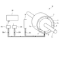
- FIG. 1 It is the schematic which shows the whole structure of a rotary machine provided with the clearance measuring device which concerns on at least 1 embodiment of this invention. It is an axial sectional view of a clearance measurement sensor according to related technology. It is a graph regarding the signal strength of the light reception signal input into a measurement part from the clearance measurement sensor of FIG. It is sectional drawing which shows typically the internal structure of the clearance measurement sensor which concerns on 1st Embodiment. It is an example of the measurement result of the received light signal input into the measurement part of FIG. It is a comparative example of FIG. It is sectional drawing which shows typically the internal structure of the clearance measurement sensor which concerns on 2nd Embodiment. It is sectional drawing which shows typically the internal structure of the clearance measurement sensor which concerns on 3rd Embodiment.
- expressions representing shapes such as quadrangular shapes and cylindrical shapes not only represent shapes such as quadrangular shapes and cylindrical shapes in a strict geometric sense, but also within the range where the same effect can be obtained. A shape including a chamfered portion or the like is also expressed.
- the expressions “comprising”, “comprising”, “comprising”, “including”, or “having” one constituent element are not exclusive expressions for excluding the existence of the other constituent elements.
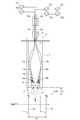
- FIG. 1 is a schematic diagram showing an overall configuration of a rotary machine including a clearance measuring device according to at least one embodiment of the present invention.
- the rotating machine 1 includes a casing 2 having a substantially cylindrical shape, and a rotating body 4 that is rotatably disposed in the casing 2.
- a clearance d is provided between the inner peripheral surface 2 a of the casing 2 and the outer peripheral surface 4 a of the rotating body 4, and the rotating body 4 connected to the rotating shaft 6 can be rotated in the casing 2.
- the rotary machine 1 is, for example, a steam turbine, a gas turbine, or a turbocharger.
- the rotating body 4 includes a plurality of moving blades arranged at predetermined intervals along the circumferential direction of the rotating shaft 6, and the outer peripheral surface 4 a of the rotating body 4 is driven by the plurality of moving blades during driving. Is formed.
- the clearance measuring device 10 includes a clearance measuring sensor 12 for measuring a clearance d provided between the inner peripheral surface 2 a of the casing 2 and the outer peripheral surface 4 a of the rotating body 4.
- the clearance measuring sensor 12 is an optical sensor, and is fixed to the casing 2 so that the detection surface P (see FIG. 4) at the tip faces the outer peripheral surface 4 a of the rotating body 4.
- the clearance measurement sensor 12 is exposed to a clearance d in a high-temperature / high-pressure environment between the casing 2 and the rotating body (rotating blade) 4. It becomes.
- the clearance measurement sensor 12 is connected to the light source unit 16 via the irradiation optical fiber 14.
- the light source unit 16 includes a light emitting element capable of emitting irradiation light.
- the light emitting element is, for example, a laser light source having a predetermined wavelength. Irradiation light from the light source unit 16 is sent to the clearance measurement sensor 12 via the irradiation optical fiber 14 and irradiated toward the outer peripheral surface 4 a of the rotating body 4.
- the irradiation light from the clearance measuring sensor 12 is reflected on the outer peripheral surface 4a of the rotating body 4, and a part of the reflected light is received by the clearance measuring sensor 12.
- the reflected light from the outer peripheral surface 4a of the rotating body 4 has a predetermined intensity cycle depending on the shape or pattern that changes in the circumferential direction (rotating direction) of the outer peripheral surface 4a of the rotating body 4.
- the “shape” is, for example, the shape of a moving blade when the rotating body 4 is a turbine
- the “pattern” is, for example, a marker (heat resistant paint or the like) having a reflectance different from that of the outer peripheral surface 4a. It shows what provides light and dark by attaching.
- the reflected light from the outer peripheral surface 4a of the rotating body 4 is received by the clearance measuring sensor 12, and the first receiving unit 22a and the second receiving unit are passed through the first light receiving optical fiber 20a and the second light receiving optical fiber 20b. 22b, respectively.
- the reflected light input to the first receiving unit 22a and the second receiving unit 22b is converted into an electrical light reception signal corresponding to the signal intensity, sent to the measuring unit 24, and used for the measurement calculation of the clearance d.
- the measurement unit 24 is an arithmetic unit that measures the clearance d based on the measurement result of the clearance measurement sensor 12, and includes an electronic arithmetic unit using a semiconductor device such as a computer.
- the measurement unit 24 is configured to implement the clearance measurement device 10 according to at least one embodiment of the present invention by executing the clearance measurement method according to at least one embodiment of the present invention based on a program installed in advance. Has been.
- the control unit 24 outputs a light emission signal to the clearance measurement sensor 12 to control the irradiation timing of the irradiation light to the outer peripheral surface 4 a of the rotating body 4 and from the outer peripheral surface 4 a of the rotating body 4.
- a light reception signal corresponding to the reflected light is acquired, and the clearance d is calculated.
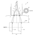
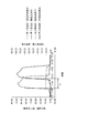
- FIG. 2 is an axial sectional view of a clearance measurement sensor according to the related art.
- the components corresponding to the clearance measurement sensor 12 according to at least one embodiment of the present invention are denoted by the same reference numerals, and redundant description will be omitted as appropriate.
- the clearance measuring sensor is arranged so that the detection surface P faces the outer peripheral surface 4a of the rotating body 4, and the irradiation optical fiber 14 connected to the light source unit 16 and the first receiving unit 22a A first light receiving optical fiber 20a connected to the second receiving unit 22b; and a second light receiving optical fiber 20b connected to the second receiving unit 22b.
- the irradiation optical fiber 14 has one end connected to the light source unit 16 (see FIG. 1) and the other end surface extending to the detection surface P.
- the irradiation light output from the light source unit 16 is transmitted through the irradiation optical fiber 14 and is irradiated from the detection surface P to the outer peripheral surface 4 a of the rotating body 4.
- the first light receiving optical fiber 20a has one end connected to the first receiver 22a (see FIG. 1) and the other end face extending to the detection surface P.
- the reflected light reflected by the outer peripheral surface 4a of the rotator 4 is received by the detection surface P and transmitted to the first receiver 22a via the first light receiving optical fiber 20a.
- One end of the second light receiving optical fiber 20b is connected to the second receiving portion 22b (see FIG. 1), and the other end surface extends to the detection surface P.
- the reflected light reflected by the outer peripheral surface 4a of the rotator 4 is received by the detection surface P and transmitted to the second receiver 22b through the second light receiving optical fiber 20b.
- the irradiation optical fiber 14 and the first light receiving optical fiber 20a are grouped together as an optical fiber group X, and a plurality of irradiation optical fibers are enclosed so as to surround the first light receiving optical fiber 20a. 14 is arranged.
- the irradiation optical fiber 14 and the second light receiving optical fiber 20b are grouped together as an optical fiber group Y, and a plurality of irradiation lights are enclosed so as to surround the second light receiving optical fiber 20b.
- a fiber 14 is arranged.
- These optical fiber groups X and Y extend along the substantially axial direction of the clearance measurement sensor, and are inclined and arranged so that the distance between them is widened on the tip side (detection surface P side). In FIG.
- the end faces of the optical fiber groups X and Y are indicated by points A and B, respectively, and virtual straight lines a and b passing through the end faces perpendicularly at the points A and B are shown. Further, as a reference point of the clearance measurement sensor, an intersection point O of the virtual straight lines a and b is shown, and an intersection angle of the virtual straight lines a and b at the intersection point O is shown as ⁇ .
- the optical fiber groups X and Y are composed of a plurality of optical fibers as described above.
- the positions of the end faces of the optical fibers X and Y are point A and point B for simplification. Are considered as one point.
- the moving blade 26 that forms the outer peripheral surface 4 a is shown by taking the case where the rotating body 4 is a turbine as an example.
- point C is a point where a corner portion (a corner portion on the front side in the rotational direction of the two corner portions) on the outer end face of the moving blade 26 intersects the virtual straight line a
- point D is on the outer end face of the moving blade 26.
- a corner (a corner on the front side in the rotational direction among the two corners) is a point where the virtual straight line b intersects.
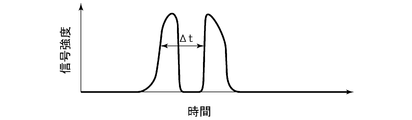
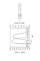
- FIG. 3 is a graph relating to the signal intensity of the received light signal input to the measurement unit 24 from the clearance measurement sensor of FIG.
- the horizontal axis indicates time
- the vertical axis indicates signal intensity.
- the received light signal is received at a time ⁇ t required for the measurement point on the outer peripheral surface 4a of the rotating body 4 (the corner on the front side in the rotational direction of the moving blade) to move from the C point to the D point.
- Two corresponding signal peaks have been detected.
- the rotation period of the rotating body 4 is T and the radius of the rotating body 4 is R
- the clearance d is expressed by the following equation. Is calculated by
- the clearance measurement sensor detects the time ⁇ t required for the outer peripheral surface 4a of the rotating body 4 to move from the point C to the point D, and calculates the clearance d based on the above equation (1). . Therefore, in order to detect the clearance d with high accuracy, it is required to detect the time ⁇ t with high accuracy and stability.
- the reflected light from the outer peripheral surface 4a of the rotating body 4 becomes unstable when the surface properties in the vicinity of the irradiation area of the irradiation light change, resulting in measurement errors. It has been found. In view of such a problem, the inventor has devised a clearance measurement device that can accurately and stably carry out clearance measurement by reducing the influence of surface properties in the vicinity of a light irradiation region.
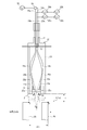
- FIG. 4 is a cross-sectional view schematically showing the internal structure of the clearance measurement sensor 12 according to the first embodiment.
- the clearance measurement sensor 12 is arranged such that the detection surface P faces the outer peripheral surface 4a of the rotating body 4, and includes a first irradiation optical fiber 14a and a second irradiation optical fiber 14b connected to the light source unit 16.
- the first light receiving optical fiber 20a and the second light receiving optical fiber 20b connected to the first receiving unit 22a and the second receiving unit 22b, respectively.
- the clearance measurement sensor 12 has a substantially cylindrical sensor body 13.
- the sensor body 13 has a first irradiation optical fiber 14a, a second irradiation optical fiber 14b, a first light receiving optical fiber 20a, and a second light receiving light in the internal space 17 from a first opening 15 provided on one end side.
- An optical fiber 20b is introduced.
- the first irradiation optical fiber 14 a, the second irradiation optical fiber 14 b, the first light receiving optical fiber 20 a, and the second light receiving optical fiber 20 b introduced into the internal space 17 have their tips at the other ends of the sensor body 13. It arrange
- the second opening 19 is closed by an isolation wall 21 made of a permeable material, and the internal space 17 is isolated from the clearance d. Therefore, even when the clearance d is in a harsh environment of high temperature and high pressure, each optical fiber accommodated in the internal space 17 is accurately protected and good reliability is ensured.
- Examples of the transparent material used for the isolation wall 21 include diamond and sapphire.
- One end of the first irradiation optical fiber 14 a and the second irradiation optical fiber 14 b is connected to the light source unit 16 (see FIG. 1), and the other end face is disposed in the internal space 17 of the sensor body 13.
- a first irradiating unit 11a and a second irradiating unit 11b for irradiating irradiation light transmitted from the light source unit 16 are respectively provided at the irradiation side ends of the first irradiating optical fiber 14a and the second irradiating optical fiber 14b. Is provided.
- the first light receiving part 23 a and the second light receiving part 23 b are arranged such that their optical axes c and d are within tolerance on the inner surface of the isolation wall 21.
- the light emitted from the first irradiating unit 11a fluoresces by the phosphor 25a, and the first irradiating unit 11a and the first light receiving unit so that the specularly reflected light from the outer peripheral surface can be received by the first light receiving unit 23a.
- the part 23a is arranged.
- the light irradiated from the second irradiating unit 11b fluoresces by the phosphor 25b, and the second irradiating unit 11b and the second light receiving unit so that the specularly reflected light from the outer peripheral surface can be received by the second light receiving unit 23b.
- the part 23b is arranged.
- the 1st irradiation part 11a and the 2nd irradiation part 11b have the left-right symmetric (optical symmetry) arrangement
- the first phosphor 25a and the second phosphor 25b are disposed on the optical axes a and b of the irradiation light output from the first irradiation unit 11a and the second irradiation unit 11b, respectively.
- the first phosphor 25a and the second phosphor 25b are excited by the irradiation light output from the first irradiation optical fiber 14a and the second irradiation optical fiber 14b, respectively, and thereby have the first wavelength ⁇ 1 and the second wavelength ⁇ 1, respectively.
- Excitation light having wavelength ⁇ 2 is generated.
- the first wavelength ⁇ 1 and the second wavelength ⁇ 2 are visible light bands, which are different from each other.
- Excitation light from the first phosphor 25 a and the second phosphor 25 b passes through the isolation wall 21 and is irradiated to the outer peripheral surface 4 a of the rotating body 4.
- the first phosphor 25a and the second phosphor 25b are such that the reflected light from the outer peripheral surface 4a of the rotating body 4 is reflected from the first phosphor 25a and the second phosphor 25 in the internal space 17 inside the isolation wall 21.
- the phosphors 25b are arranged so as to be spaced from each other to the extent that they can pass without interfering with the phosphors 25b. Thereby, the wavelength of each irradiation light can be converted appropriately, avoiding the influence on the reflected light from the outer peripheral surface 4a of the rotary body 4.
- the light source light output from the common light source unit 16 is split by the optical coupler 29 and supplied to the first irradiation optical fiber 14a and the second irradiation optical fiber 14b, and the clearance.
- the first phosphor 25a and the second phosphor 25b provided in the measurement sensor 12 perform wavelength conversion to the first wavelength ⁇ 1 and the second wavelength ⁇ 2, respectively.
- each of the first light receiving optical fiber 20a and the second light receiving optical fiber 20b is connected to the first receiving unit 22a and the second receiving unit 22b (see FIG. 1), and the other end is disposed in the internal space 17.
- the A first light receiving portion 23a and a second light receiving portion 23b for receiving reflected light from the outer peripheral surface 4a are provided at the end on the inner space 17 side, and the first light receiving portion 23a and the second light receiving portion are provided.
- the reflected light received by 23b is transmitted to the first receiver 22a and the second receiver 22b via the first light receiving optical fiber 20a and the second light receiving optical fiber 20b, respectively. .
- the first light receiving part 23a and the second light receiving part 23b are arranged at positions where the reflected light transmitted through the isolation wall 21 can be received, and as described above, in particular, the optical axes c and d are isolated from each other. It is arranged on the inner surface of the wall 21 with a tolerance.
- the first light receiving unit 23a is disposed at a position where regular reflection light from the outer peripheral surface by the light irradiated from the first irradiation unit 11a can be received
- the second light receiving unit 23b It arrange
- the first light receiving portion 23a and the second light receiving portion 23b have a bilaterally symmetric (optically symmetric) arrangement, and are inclined so that the distance between them is reduced toward the second opening 19. is doing.
- the first irradiation unit 11a, the second irradiation unit 11b, the first light receiving unit 23a, and the second light receiving unit 23b are arranged in such a positional relationship in the internal space 17, so that the irradiation from the first irradiation unit 11a is performed. Reflected light by the light is received by the first light receiving unit 23a, and reflected light by the irradiated light from the second irradiation unit 11b is received by the second light receiving unit 23b.
- the second light receiving optical fiber 20b can receive the specularly reflected light component due to the geometric positional relationship of each optical fiber, but the first light receiving optical fiber 20a can receive the positive reflected light.
- the reflected light component cannot be received, and the scattered light component of the reflected light is mainly received.
- the scattered light component of the reflected light tends to become unstable when the surface properties in the vicinity of the irradiated area of the irradiated light change, causing a measurement error.
- the first irradiation unit 11a, the second irradiation unit 11b, the first light receiving unit 23a, and the second light receiving unit 23b are arranged in such a positional relationship, so that the first light receiving unit 23a and Both of the second light receiving parts 23b are configured to receive a regular reflection light component. Therefore, a stable measurement result can be obtained regardless of the surface properties in the vicinity of the irradiation region, and high-accuracy clearance measurement with little measurement error can be performed.
- the first light receiving optical fiber 20a and the second light receiving optical fiber 20b include a first filter unit 30a and a second filter unit 30b between the first receiving unit 22a and the second receiving unit 22b, respectively.
- the first filter unit 30a and the second filter unit 30b have transmission bands corresponding to the first wavelength ⁇ 1 and the second wavelength ⁇ 2, respectively.
- the reflected light received by the first light receiving unit 23a includes not only the regular reflected light component having the first wavelength ⁇ 1 from the target first irradiation unit 11a but also the second wavelength from the second irradiation unit 11b.
- a scattered light component having ⁇ 2 is included.
- Such a scattered light component having the second wavelength ⁇ 2 becomes a noise component for the first receiver 22a, and causes a measurement error to increase. Therefore, such unnecessary scattered light components can be removed by filtering by the first filter unit 30a.
- the regular reflected light component which has the 1st wavelength (lambda) 1 by the irradiation light from the target 1st irradiation part 11a can be extracted, and favorable measurement accuracy is obtained.
- the reflected light received by the second light receiving unit 23b in addition to the specularly reflected light component having the second wavelength ⁇ 2 from the target second irradiation unit 11b, there is not less than the first irradiation unit 11a.
- a scattered light component having the first wavelength ⁇ 1 is included.
- Such a scattered light component having the first wavelength ⁇ 1 becomes a noise component for the second receiver 22b, and causes a measurement error to increase. Therefore, the unnecessary scattered light component can be removed by filtering by the second filter unit 30b.
- the regular reflection light component which has the 2nd wavelength (lambda) 2 from the target 2nd irradiation part 11b can be extracted, and favorable measurement accuracy is obtained.
- FIG. 5 is an example of the measurement result of the received light signal input to the measurement unit 24 of FIG. 4, and FIG. 6 is a comparative example of FIG.
- the first receiving unit 22a and the second receiving unit 22b perform the detection separated into the first wavelength ⁇ 1 and the second wavelength ⁇ 2, respectively, thereby distorting the waveform of the received light signal.
- the results were similar for both waveforms. This indicates that the outer peripheral surface 4a of the rotating body 4 can be accurately captured, and accurate clearance measurement is possible.
- the comparative example of FIG. 6 receives light from the first light receiving unit 23a and the second light receiving unit 23b without passing through the first filter unit 30a and the second filter unit 30b in the first receiving unit 22a and the second receiving unit 22b.
- the received light signal based on the result is measured.
- the measured waveform is distorted, and both waveforms are also greatly different.
- the first receiving unit 22 a and the second receiving unit 22 a and the second receiving unit 22 a are filtered by performing filtering in the first filter unit 30 a and the second filter unit 30 a. It has been demonstrated that accurate detection can be performed by the two receiving units 22b.
- the outer peripheral surface 4a of the rotating body 4 is irradiated with the irradiation light having the first wavelength ⁇ 1 and the second wavelength ⁇ 2, respectively, and the received reflected light is converted into the first wavelength ⁇ 1. And a filtering process corresponding to the second wavelength ⁇ 2.
- the time ⁇ t is measured well, and as a result, the clearance d can be measured accurately and stably.
- FIG. 7 is a sectional view schematically showing the internal structure of the clearance measurement sensor 12 according to the second embodiment.
- components corresponding to the above-described embodiment will be denoted by common reference numerals, and redundant description will be omitted as appropriate.
- the first irradiation optical fiber 14a and the second irradiation optical fiber 14b introduced into the sensor main body 13 of the clearance measurement sensor 12 include two independent first light source portions 16a and second light source portions 16b. This is different from the first embodiment described above.
- the first light source unit 16a and the second light source unit 16b are light sources that output irradiation light having a first wavelength ⁇ 1 and a second wavelength ⁇ 2, respectively.
- the irradiation light having the first wavelength ⁇ 1 output from the first light source unit 16a is transmitted through the first irradiation optical fiber 14a and is irradiated from the first irradiation unit 11a.
- the irradiation light irradiated from the first irradiation unit 11a is homogenized by the diffusion plate 40 disposed on the optical path, passes through the isolation wall 21 made of a transparent material, and is irradiated to the outer peripheral surface 4a of the rotating body 4. Is done.
- the reflected light from the outer peripheral surface 4a of the rotary body 4 is received by the 1st light-receiving part 23a, and is detected by the 1st receiving part 22a via the 1st filter part 30a from the 1st light-receiving optical fiber 20a. .
- the irradiation light having the second wavelength ⁇ 2 output from the second light source unit 16b is transmitted through the second irradiation optical fiber 14b and is irradiated from the second irradiation unit 11b.
- the irradiation light irradiated from the second irradiation unit 11b is homogenized by the diffusion plate 40 disposed on the optical path, passes through the isolation wall 21 made of a transparent material, and is irradiated to the outer peripheral surface 4a of the rotating body 4. Is done. Then, the reflected light from the outer peripheral surface 4a of the rotating body 4 is received by the second light receiving unit 23b, and detected by the second receiving unit 22b from the second light receiving optical fiber 20b via the second filter unit 30b. .
- the first phosphor 25a and the internal phosphor 17 in the internal space 17 of the sensor body 13 as in the first embodiment. Irradiation light having the first wavelength ⁇ 1 and the second wavelength ⁇ 2 can be irradiated without arranging the second phosphor 25b. Therefore, the sensor structure can be simplified and it is advantageous for miniaturization.
- FIG. 8 is a cross-sectional view schematically showing the internal structure of the clearance measurement sensor 12 according to the third embodiment.
- components corresponding to the above-described embodiment will be denoted by common reference numerals, and redundant description will be omitted as appropriate.
- the optical fiber assembly 50a includes a plurality of optical fibers.
- the first irradiation optical fiber 14a introduces the irradiation light output from the first light source unit 16a into the internal space of the sensor main body 13, and irradiates the optical fiber aggregate 50a provided at the tip thereof toward the outer peripheral surface 4a.
- the optical fiber assembly 50a is a bundle of a plurality of optical fibers, and is configured to be able to divide and irradiate the irradiation light transmitted by the first irradiation optical fiber 14a. Therefore, in the optical fiber assembly 50a, a wider irradiation surface can be obtained without arranging the diffusion plate 40 in the internal space 17 as in the second embodiment, and uniform light irradiation can be performed.
- the irradiation light output from the second light source unit 16b is introduced into the internal space of the sensor main body 13, and the optical fiber aggregate 50b provided at the tip thereof is directed toward the outer peripheral surface 4a. Irradiate.
- the optical fiber assembly 50b is a bundle of a plurality of optical fibers, and is configured to be able to divide and irradiate the irradiation light transmitted by the second irradiation optical fiber 14b. Therefore, in the optical fiber assembly 50b, a wider irradiation surface can be obtained without arranging the diffusion plate 40 in the internal space 17 as in the second embodiment, and uniform light irradiation can be performed.
- the configuration of the clearance measurement sensor 12 can be simplified, and it is advantageous for downsizing.
- the present disclosure can be used for a clearance measuring device for measuring a clearance formed between an inner peripheral surface of a casing having a cylindrical shape and an outer peripheral surface of a rotating body rotating in the casing, and the clearance measuring device.
- the present invention can be used for a clearance measurement method that can be implemented by a simple clearance measurement sensor and the clearance measurement device.
Landscapes
- Engineering & Computer Science (AREA)
- Physics & Mathematics (AREA)
- General Physics & Mathematics (AREA)
- Mechanical Engineering (AREA)
- General Engineering & Computer Science (AREA)
- Chemical & Material Sciences (AREA)
- Combustion & Propulsion (AREA)
- Length Measuring Devices By Optical Means (AREA)
Priority Applications (2)
| Application Number | Priority Date | Filing Date | Title |
|---|---|---|---|
| US16/606,047 US11073378B2 (en) | 2017-04-25 | 2018-04-24 | Clearance measurement device, clearance measurement sensor, and clearance measurement method |
| CN201880024668.6A CN110546453B (zh) | 2017-04-25 | 2018-04-24 | 间隙测量装置、间隙测量传感器及间隙测量方法 |
Applications Claiming Priority (2)
| Application Number | Priority Date | Filing Date | Title |
|---|---|---|---|
| JP2017-086222 | 2017-04-25 | ||
| JP2017086222A JP6959027B2 (ja) | 2017-04-25 | 2017-04-25 | クリアランス計測装置、クリアランス計測センサ及びクリアランス計測方法 |
Publications (1)
| Publication Number | Publication Date |
|---|---|
| WO2018199076A1 true WO2018199076A1 (ja) | 2018-11-01 |
Family
ID=63919168
Family Applications (1)
| Application Number | Title | Priority Date | Filing Date |
|---|---|---|---|
| PCT/JP2018/016574 Ceased WO2018199076A1 (ja) | 2017-04-25 | 2018-04-24 | クリアランス計測装置、クリアランス計測センサ及びクリアランス計測方法 |
Country Status (4)
| Country | Link |
|---|---|
| US (1) | US11073378B2 (enExample) |
| JP (1) | JP6959027B2 (enExample) |
| CN (1) | CN110546453B (enExample) |
| WO (1) | WO2018199076A1 (enExample) |
Cited By (1)
| Publication number | Priority date | Publication date | Assignee | Title |
|---|---|---|---|---|
| CN114440781A (zh) * | 2022-01-21 | 2022-05-06 | 中国工程物理研究院流体物理研究所 | 一种间隙传感器、间隙测量方法及测量装置 |
Families Citing this family (1)
| Publication number | Priority date | Publication date | Assignee | Title |
|---|---|---|---|---|
| US12339113B2 (en) * | 2022-06-30 | 2025-06-24 | Ge Infrastructure Technology Llc | Apparatus and method for transmitting radiation to a rotating component |
Citations (6)
| Publication number | Priority date | Publication date | Assignee | Title |
|---|---|---|---|---|
| JPS59142408A (ja) * | 1983-02-02 | 1984-08-15 | Ishikawajima Harima Heavy Ind Co Ltd | 翼端隙間の測定装置 |
| US4766323A (en) * | 1986-08-29 | 1988-08-23 | B. C. Hydro | Method and apparatus for determining the distance of an object |
| JPH0430105A (ja) * | 1990-05-26 | 1992-02-03 | Matsushita Electric Works Ltd | ファイバ光源装置 |
| JP2009168602A (ja) * | 2008-01-16 | 2009-07-30 | Ojima Shisaku Kenkyusho:Kk | エンコーダおよびエンコーダ構成用検出装置 |
| JP2015001414A (ja) * | 2013-06-14 | 2015-01-05 | 三菱重工業株式会社 | チップクリアランス計測装置 |
| JP2016017921A (ja) * | 2014-07-10 | 2016-02-01 | オリンパス株式会社 | 観察システム |
Family Cites Families (15)
| Publication number | Priority date | Publication date | Assignee | Title |
|---|---|---|---|---|
| US4326804A (en) * | 1980-02-11 | 1982-04-27 | General Electric Company | Apparatus and method for optical clearance determination |
| US5818242A (en) * | 1996-05-08 | 1998-10-06 | United Technologies Corporation | Microwave recess distance and air-path clearance sensor |
| JP2003254091A (ja) * | 2002-03-04 | 2003-09-10 | Ishikawajima Harima Heavy Ind Co Ltd | 圧縮機のチップクリアランス制御装置及び制御方法 |
| JP4148689B2 (ja) | 2002-03-15 | 2008-09-10 | 株式会社東芝 | 回転体計測装置 |
| DE102007051027A1 (de) * | 2007-10-25 | 2009-04-30 | Mtu Aero Engines Gmbh | Strömungsmaschine, Spaltmesssystem und Verfahren zum Ermitteln eines Rotorspaltes |
| US8009939B2 (en) * | 2008-09-30 | 2011-08-30 | General Electric Company | Fiberoptic clearance detection system and method |
| US9267378B2 (en) * | 2012-06-27 | 2016-02-23 | General Electric Company | Turbomachine monitoring system and method |
| EP2698502A1 (en) * | 2012-08-13 | 2014-02-19 | Alstom Technology Ltd | Method for measuring the cold build blade tip clearance of a turbomachine and tip clearance measuring arrangment for conducting said method |
| CN203100688U (zh) * | 2013-02-28 | 2013-07-31 | 济南大学 | 一种测量旋转叶片叶尖间隙的光纤传感器 |
| CN103438814B (zh) | 2013-08-29 | 2016-03-16 | 中国科学院工程热物理研究所 | 一种叶尖间隙光纤测量方法及装置 |
| US9513117B2 (en) * | 2013-10-02 | 2016-12-06 | Siemens Energy, Inc. | Situ blade mounted tip gap measurement for turbines |
| WO2015199054A1 (ja) * | 2014-06-27 | 2015-12-30 | 株式会社キーエンス | 多波長光電測定装置、共焦点測定装置、干渉測定装置及びカラー測定装置 |
| MY181105A (en) * | 2014-10-31 | 2020-12-17 | Halliburton Energy Services Inc | Flow distribution assemblies with shunt tubes and erosion-resistant shunt nozzles |
| CN104501728A (zh) * | 2014-12-12 | 2015-04-08 | 天津大学 | 一种基于全光纤叶尖定时的叶尖间隙测量方法 |
| JP6596399B2 (ja) | 2016-08-30 | 2019-10-23 | 三菱重工業株式会社 | クリアランス計測装置およびクリアランス制御システム |
-
2017
- 2017-04-25 JP JP2017086222A patent/JP6959027B2/ja active Active
-
2018
- 2018-04-24 CN CN201880024668.6A patent/CN110546453B/zh active Active
- 2018-04-24 WO PCT/JP2018/016574 patent/WO2018199076A1/ja not_active Ceased
- 2018-04-24 US US16/606,047 patent/US11073378B2/en active Active
Patent Citations (6)
| Publication number | Priority date | Publication date | Assignee | Title |
|---|---|---|---|---|
| JPS59142408A (ja) * | 1983-02-02 | 1984-08-15 | Ishikawajima Harima Heavy Ind Co Ltd | 翼端隙間の測定装置 |
| US4766323A (en) * | 1986-08-29 | 1988-08-23 | B. C. Hydro | Method and apparatus for determining the distance of an object |
| JPH0430105A (ja) * | 1990-05-26 | 1992-02-03 | Matsushita Electric Works Ltd | ファイバ光源装置 |
| JP2009168602A (ja) * | 2008-01-16 | 2009-07-30 | Ojima Shisaku Kenkyusho:Kk | エンコーダおよびエンコーダ構成用検出装置 |
| JP2015001414A (ja) * | 2013-06-14 | 2015-01-05 | 三菱重工業株式会社 | チップクリアランス計測装置 |
| JP2016017921A (ja) * | 2014-07-10 | 2016-02-01 | オリンパス株式会社 | 観察システム |
Cited By (1)
| Publication number | Priority date | Publication date | Assignee | Title |
|---|---|---|---|---|
| CN114440781A (zh) * | 2022-01-21 | 2022-05-06 | 中国工程物理研究院流体物理研究所 | 一种间隙传感器、间隙测量方法及测量装置 |
Also Published As
| Publication number | Publication date |
|---|---|
| US20200041254A1 (en) | 2020-02-06 |
| JP6959027B2 (ja) | 2021-11-02 |
| JP2018185195A (ja) | 2018-11-22 |
| CN110546453A (zh) | 2019-12-06 |
| CN110546453B (zh) | 2021-07-06 |
| US11073378B2 (en) | 2021-07-27 |
Similar Documents
| Publication | Publication Date | Title |
|---|---|---|
| JP6532061B2 (ja) | 光計測装置、光計測方法及び回転機械 | |
| JP6247752B2 (ja) | 距離差を取得するための光学測定装置および光学測定方法 | |
| KR101331437B1 (ko) | 반응 해석 장치, 기록 매체, 계측 시스템, 및 제어 시스템 | |
| US20100171956A1 (en) | Alignment Free Single-Ended Optical Probe and Methods for Spectroscopic Measurements in a Gas Turbine Engine | |
| CN109416244B (zh) | 间隙计测装置和间隙控制系统 | |
| CN108027231B (zh) | 光纤探头、光纤测量装置以及间距控制系统 | |
| US10393501B2 (en) | Device for determining a 3D structure of an object | |
| JP2012058068A5 (enExample) | ||
| CN104820195A (zh) | 磁场测量装置 | |
| CN110376213B (zh) | 光学检测系统及方法 | |
| WO2018199076A1 (ja) | クリアランス計測装置、クリアランス計測センサ及びクリアランス計測方法 | |
| KR20160102161A (ko) | 생체정보 측정 장치 | |
| JP5079562B2 (ja) | 輪郭形状測定方法 | |
| JP2018185195A5 (enExample) | ||
| CN109313013B (zh) | 光学传感器 | |
| KR101664470B1 (ko) | 빔 스플리터의 후면 반사를 이용한 다중 광경로 레이저 광학계 | |
| JP6629118B2 (ja) | 光学センサ及び回転機械 | |
| KR101663003B1 (ko) | 곡면 거울이 구비된 가스셀 및 이를 이용한 푸리에 변환 적외선 분광기 | |
| JP6327041B2 (ja) | 分光測定装置 | |
| JP5689918B2 (ja) | 試料の状態を評価するための装置及び方法 | |
| JP2015025771A (ja) | 内形測定装置 | |
| JP2006220582A (ja) | センシング装置 | |
| HK1241015A1 (en) | Device for determining a 3d structure of an object | |
| KR20190023856A (ko) | 다종가스 동시 측정 tdlas 정렬 시스템 | |
| KR20170036191A (ko) | 페이스트의 단면적 측정 방법 |
Legal Events
| Date | Code | Title | Description |
|---|---|---|---|
| 121 | Ep: the epo has been informed by wipo that ep was designated in this application |
Ref document number: 18790119 Country of ref document: EP Kind code of ref document: A1 |
|
| NENP | Non-entry into the national phase |
Ref country code: DE |
|
| 122 | Ep: pct application non-entry in european phase |
Ref document number: 18790119 Country of ref document: EP Kind code of ref document: A1 |