WO2018198907A1 - 車両用収納装置 - Google Patents
車両用収納装置 Download PDFInfo
- Publication number
- WO2018198907A1 WO2018198907A1 PCT/JP2018/016021 JP2018016021W WO2018198907A1 WO 2018198907 A1 WO2018198907 A1 WO 2018198907A1 JP 2018016021 W JP2018016021 W JP 2018016021W WO 2018198907 A1 WO2018198907 A1 WO 2018198907A1
- Authority
- WO
- WIPO (PCT)
- Prior art keywords
- storage device
- case member
- cushioning
- cushioning material
- holder
- Prior art date
- Legal status (The legal status is an assumption and is not a legal conclusion. Google has not performed a legal analysis and makes no representation as to the accuracy of the status listed.)
- Ceased
Links
Images



Classifications
-
- B—PERFORMING OPERATIONS; TRANSPORTING
- B60—VEHICLES IN GENERAL
- B60R—VEHICLES, VEHICLE FITTINGS, OR VEHICLE PARTS, NOT OTHERWISE PROVIDED FOR
- B60R7/00—Stowing or holding appliances inside vehicle primarily intended for personal property smaller than suit-cases, e.g. travelling articles, or maps
- B60R7/04—Stowing or holding appliances inside vehicle primarily intended for personal property smaller than suit-cases, e.g. travelling articles, or maps in driver or passenger space, e.g. using racks
-
- B—PERFORMING OPERATIONS; TRANSPORTING
- B60—VEHICLES IN GENERAL
- B60R—VEHICLES, VEHICLE FITTINGS, OR VEHICLE PARTS, NOT OTHERWISE PROVIDED FOR
- B60R7/00—Stowing or holding appliances inside vehicle primarily intended for personal property smaller than suit-cases, e.g. travelling articles, or maps
- B60R7/08—Disposition of racks, clips, holders, containers or the like for supporting specific articles
- B60R7/082—Disposition of racks, clips, holders, containers or the like for supporting specific articles for supporting spectacles
-
- B—PERFORMING OPERATIONS; TRANSPORTING
- B60—VEHICLES IN GENERAL
- B60R—VEHICLES, VEHICLE FITTINGS, OR VEHICLE PARTS, NOT OTHERWISE PROVIDED FOR
- B60R11/00—Arrangements for holding or mounting articles, not otherwise provided for
- B60R2011/0001—Arrangements for holding or mounting articles, not otherwise provided for characterised by position
- B60R2011/0003—Arrangements for holding or mounting articles, not otherwise provided for characterised by position inside the vehicle
- B60R2011/0028—Ceiling, e.g. roof rails
-
- B—PERFORMING OPERATIONS; TRANSPORTING
- B60—VEHICLES IN GENERAL
- B60R—VEHICLES, VEHICLE FITTINGS, OR VEHICLE PARTS, NOT OTHERWISE PROVIDED FOR
- B60R11/00—Arrangements for holding or mounting articles, not otherwise provided for
- B60R2011/0042—Arrangements for holding or mounting articles, not otherwise provided for characterised by mounting means
- B60R2011/0043—Arrangements for holding or mounting articles, not otherwise provided for characterised by mounting means for integrated articles, i.e. not substantially protruding from the surrounding parts
Definitions
- the present invention relates to a vehicular storage device.
- Examples of the vehicular storage device to be used include various console boxes provided in the passenger compartment, a console lid for opening and closing the console box, a cup holder for storing and holding cups, and a spectacle holder for storing spectacles.
- 10 (a) and 10 (b) show a console lid disclosed in Patent Document 1 as an example, FIG. 10 (a) is a longitudinal sectional view thereof, and FIG. 10 (b) is an enlarged view of a main part.
- the console lid shown in FIGS. 10A and 10B is attached in a state where a lid inner (corresponding to one member of the present invention) 3 is overlapped with a lid outer (corresponding to the other member of the present invention) 1, and a console not shown.
- the box is assembled to the box via a hinge so that it can be switched between a closed state and an open state, and in the open state, small items can be accommodated and held in a recess on the lower surface side of the lid.
- the lid inner 3 is provided with a lock member that keeps the console lid closed with respect to the console box.
- the main portion is formed by engaging and locking the engagement piece 23a which is an engagement portion provided in the vicinity of the lock member in the lid inner 3 and the recess 25a which is a locking portion provided in the lid outer 1. In addition to reinforcing the periphery of the lock member, it prevents rattling between members. Further, in this fitting structure, as shown in FIG. 10B, inclined portions 33 and 33 are provided on the inner surface of the concave portion 25a that is a locking portion so as to gradually approach the concave portion center line as it goes deeper. 23a and the inclined portions 33, 33 of the recess 25a are tightly sandwiched with a clamping pressure.
- Patent Document 1 by providing an inclined portion in a direction gradually approaching the concave portion center line as it goes deeper on the inner surface of the concave portion that is a locking portion, the engagement piece is tightly sandwiched by a wedge action. It is described that it is possible to reliably prevent rattling after temporary fastening and positioning, as well as fastening.
- the engaging piece is fitted to the inclined portion on the concave side, if the lid out and the lid inner are not accurately formed, it is impossible to fit as designed, and correction or tuning is difficult. Depending on the dimensional error, it may cause noise. Such a problem becomes conspicuous in a configuration in which the engagement piece and the recess are fitted at a plurality of locations.
- a cushioning material such as a non-woven fabric is adhered or stuck to one member or the other member, but the work man-hours increase with the number of members and the cost increases. It becomes.
- an object of the present invention is to easily tune a structure having a cushioning material together with the one member and the other member, and to suppress the rattling with a minimum cost by using the cushioning material.
- An object of the present invention is to provide a vehicular storage device. Other purposes will be clarified in the description below.
- the vehicle storage apparatus including the other member that is capable of accommodating an article on the inside and attached in a state where at least a part of the member is overlapped on the outside
- One of the members has a cushioning material that can contact the article disposed and accommodated inside, and the cushioning material partially extends a cushioning portion that is sandwiched between the one member and the other member. It is characterized by being formed.
- the buffer portion is a portion that acts to prevent rattling by absorbing the gap between the members by being interposed between the one member and the other member.
- the cushioning material is preferably a soft material such as rubber, but is not limited thereto.
- a non-woven fabric or a similar material may be used.
- the present invention described above includes the following aspects. (1) In the state where the cushioning material is positioned and arranged on the inner side of the one member, the cushioning portion is arranged to protrude outward from an opening provided in the one member. In this aspect, when the buffer portion is arranged outside the opening provided in the one member and can be sandwiched between the other member, the buffer portion can be easily arranged at any position of the one member. The degree of freedom can be expanded. (2) In the state where the cushioning material is positioned and arranged on the inner side of the one member, the cushioning portion protrudes outside through the peripheral end of the one member.
- the buffer portion when the buffer portion is arranged outside the peripheral end portion of the one member and can be sandwiched between the other member, processing of an opening or the like is performed on the one member as compared with the above-described aspect (1). Since it becomes unnecessary, it can be carried out easily without fear of a decrease in rigidity.
- the cushioning material is configured to have a substantially planar shape having corners and chamfers part of the corners of the cushioning part.
- the buffer portion is easy to form because it has a substantially planar shape with corners, and the buffer portion is arranged and positioned in the operation of assembling the buffer member due to the presence of chamfering provided at part of the corners.
- the feeding operation can be performed satisfactorily.
- the one member includes a rib-shaped sandwiching protrusion for sandwiching the buffer portion with the other member. In this aspect, for example, rattling can be reliably absorbed compared to a configuration in which the surfaces are sandwiched between surfaces.
- the other member is attached to the one member by engagement of a convex portion and a concave portion.
- the other member can be easily assembled to the one member, and in addition, since the rattling of both the members is suppressed due to the presence of the buffer portion, the engagement strength is stably maintained and the reliability can be improved.
- the one member is a case member having a storage space
- the other member is an outer member disposed on an outer surface portion of the case member
- the cushioning material is disposed in the storage space.
- the structure is a soft material such as rubber.
- a spectacle holder, a cup holder, or the like that preferably reduces the impact by applying the stored article to the buffer member.
- the occurrence of rattling is suppressed in a state where the one member and the other member are restricted or restrained from being rattled by the buffer portion interposed therebetween.
- This advantage is because the buffer portion only needs to be sandwiched between both members, so that the processing accuracy is eased and tuning is facilitated as compared to the above-mentioned literature 1, and the buffer portion for clamping may be added to the buffer material. It can be carried out at a low cost.
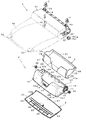
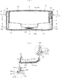
- FIG. 1 It is a conceptual diagram of the storage apparatus for vehicles which puts the spectacles etc. which concern on this invention form, (a) is a schematic side view which shows the closed state of a holder, (b) is a schematic side view which shows the open state of a holder. It is a general
- (A) is a top view of the holder, and (b) is a cross-sectional view taken along line AA of (a).
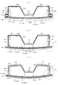
- 3A is a cross-sectional view taken along line BB in FIG. 3A
- FIG. 3B is a cross-sectional view taken along line CC in FIG. 3A
- FIG. 3C is a cross-sectional view taken along line DD in FIG. is there.
- 4A is an enlarged view of a portion B1 in FIG. 4A
- FIG. 4B is an enlarged view of a portion C1 in FIG. 4B
- FIG. 4C is an enlarged sectional view of a portion D1 in FIG. .
- the case member single goods which comprise the said holder are shown, (a) is a front view, (b) is a top view, (c) is a bottom view.
- the outer member single item which comprises the said holder is shown, (a) is a front view, (b) is a top view, (c) is a bottom view.
- the cushioning material single item which comprises the said holder is shown, (a) is a front view, (b) is a top view, (c) is a bottom view.
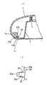
- the modification of this invention is shown, (a) is a schematic half sectional view which shows a member relationship, (b) is a schematic half sectional view which shows an assembly completion state.
- the console lid which is a storage device disclosed in Patent Document 1 is shown, (a) shows FIG. 4 of Document 1, and (b) shows FIG.
- the vehicle storage device subject to the invention is not limited to the holder that stores and holds the glasses and the like mentioned in the embodiments, but includes, for example, a cup holder, a console box, a console lid with a storage recess such as Document 1, and the like. It is embodied as a structure.
- This vehicle storage device is an example of storing articles such as glasses (not shown) as shown in FIGS. 1 (a) and 1 (b) and FIG. 2, and the holder 4 is provided on the ceiling side of the passenger compartment.
- the storage position arranged substantially flush with respect to the holder installation portion 5 as shown in FIG. 1A and the shaft portions 17 and 17 on both sides as shown in FIG. It is a type that can be switched to the use position.
- the holder installation part 5 is integrally formed with an arrangement part 51 having an inverted concave section for inserting and removing the holder 4 on the front side of the main body 50 into which various devices are incorporated. , And a pair of upright pieces 53 that are provided on both front sides and support the metal clip 7, and the like, and are mounted on the vehicle interior ceiling side using these.
- the placement portion 51 is located near the boundary with the main body 50 and is provided with a mounting hole 55 provided in the middle of the left and right sides, a shaft hole 56 provided on both sides on the same axis, and a shaft hole 56 on one side surface.
- the mounting hole 55 is fitted with a latch 8 as a locking means.
- the shaft hole 56 pivotally fits and supports the shaft portions 17 on both sides provided in the holder 4, that is, the case member 1.
- a damper 6 as a braking means is mounted in the mounting hole 57.
- the latch 8 is an engagement provided on the case member constituting the holder 4 by releasing the pressing force when the holder 4 is pushed in the storing direction against the urging force of the springs 9A and 9B.
- the piece 15) is locked and locked in the retracted position. Further, when the holder 4 is pushed again in the retracted direction and the pushing force is released, the locking is released and the holder 4 is switched to the use position by the urging force (for example, Japanese Patent Application Laid-Open No. 2007-308977 or Japanese Patent Application Laid-Open No. 2007-308977). 2013-116710).
- the heel damper 6 has a main body 6a, a rotation gear 6b, and the like, and is attached by engagement or the like while being positioned in the attachment hole 57.
- the damper 6 is composed of a known rotary oil damper or the like, and is mounted on an output shaft (not shown) in which the rotating gear 6b receives the resistance of the hydraulic oil. In the mounted state, the rotating gear 6 b is engaged with the gear portion 18 provided on the case member 1 constituting the holder 4. The damper 6 brakes so that the holder 4 is gently rotated when the holder 4 is switched from the storage position to the use position by the urging force.
- the holder 4 includes a case member 1 that forms a storage space in which a target article (glasses in this example, but may be another article) can be stored and held with a margin, and at least outside the case member 1.
- the outer member 2 is attached in a state where a part thereof is overlapped, and the cushioning material 3 that is disposed inside the case member 1 and accommodates glasses (not shown) or other articles accommodated therein.
- the contrivance points are, in particular, a configuration in which the cushioning material 3 extends partly from the cushioning portion 37 (see FIG. 2 and FIG. 8C), and the cushioning portion 37 is opened to the outer surface side of the case member 1.
- the buffer portion 35 is sandwiched between the case member 1 and the outer member 2.
- the case member 1 and the outer member 2 are injection molded resin molded products, and the cushioning material 3 is a rubber molded product. However, other materials can be used.
- the case member 1 includes a bottom wall 10 having a substantially rectangular plate shape, a front wall 11 erected on the front edge and the rear edge of the bottom wall 10, and a rear wall.
- the housing space is defined by the wall 12 and the side walls 13 and 13 that are erected slightly inward from both side edges of the bottom wall 10.
- the heel bottom wall 10 is between the side walls 13 and is cut out into a rectangular opening 14 from approximately the middle in the front-rear direction to the front of the rear wall 12.
- the bottom 10 has a plurality of holes 10a provided close to the front wall 11, a plurality of protrusions 10b provided on the end surface on the rear wall 12 side and projecting rearward, and a plurality on the end surface on the front wall 11 side.
- a plurality of convex portions 10c projecting forward and projecting to the left or right by a plurality of projections 10d on both end faces, and a concave portion 14a provided substantially in the middle between the left and right sides in communication with the opening 14.
- the heel rear wall 12 is formed as a wall that is considerably higher than the front wall 11, and the left-right middle is notched into an inverted trapezoidal opening 12 a.
- the edge of the opening 12a has an engagement piece 15 that becomes wider as it goes from top to bottom and projects from the flat portion of the bottom portion.
- ribs 12b project in the width direction on both sides of the opening 12a as shown in FIG.
- Each side wall 13 has an arcuate portion 16 provided between the side wall side of the bottom wall 10, a shaft portion 17 protruding from the center of the arcuate portion 16, and an outer side of one arcuate portion 16.
- An arcuate gear portion 18 that is provided and meshes with the rotary gear 6b of the damper is provided.
- the shaft portions 17 on both sides are located on the coaxial line, and are fitted to the shaft holes 56 provided on both sides of the arrangement portion 51 of the holder installation portion so as to be rotatable.
- coil-shaped springs 9 ⁇ / b> A and 9 ⁇ / b> B are disposed between the arc-shaped portion 16 and the shaft portion 17.
- Each of the springs 9A and 9B is engaged with a hook portion provided in the vicinity of the arc-shaped portion 16 while one end portion is locked in a hole portion (not shown) provided in the arrangement portion 51 and the other end portion develops a biasing force.
- the holder 4 is assembled in the locked state and biases the holder 4 toward the use position.
- Reference numeral 13a denotes an overhanging portion provided on the inner surface of the side wall 13 and provided on the front side.
- the outer member 2 is sometimes referred to as a decorative board, and has a substantially rectangular shape covering the outer surface of the bottom wall 10 of the case member as shown in FIGS. 2 and 7A to 7C.
- the front wall 21 and the rear wall 22 are erected on the front and rear edges of the bottom wall 20, and the side walls 23 and 23 are erected on both edges of the bottom wall 20.
- the front wall 21 is provided with a plurality of recesses 21a that engage with the corresponding protrusions 10c of the case member.
- the rear wall 22 is provided with a plurality of concave portions 22a that engage with the corresponding convex portions 10b of the case member.
- Each side wall 23 is provided with a plurality of recesses 23a that engage with the corresponding protrusions 10d of the case member.
- the outer member 2 is fixed to the case member 1 by engaging each of the four sides thereof.
- each side wall 23 is provided with a recessed portion 23b at a location facing the shaft portion 17 of the case member.
- this hollow part 23b is a location which receives the corresponding part of a spring in the state which the springs 9A and 9B supported the coil part to the axial part 17, you may abbreviate
- a plurality of ribs 25 extending in the width direction and the front-rear direction and a single U-shaped rib 26 projecting in the center are provided between the front wall and the rear wall 22. Yes.
- the rib 25 is exposed to the opening 14 of the case member and can receive the corresponding portion of the cushioning material 3.
- the rib 26 can engage with the recess 14a of the case member.
- the cushioning material 3 protects the glasses and the like housed inside the case by being assembled inside the case member 1, and as shown in FIGS. 2 and 8 (a) to (c),
- a bottom wall 30 that covers the bottom wall 10 and the opening 14, a front wall 31 that stands on the front edge of the bottom wall 30 and is disposed along the inner surface of the front wall 11 of the case member, and a rear edge of the bottom wall 30
- a rear wall 32 erected and disposed along the inner surface of the rear wall 12 of the case member, and left and right side walls erected on both edges of the bottom wall 30 and disposed along the inner surface of the corresponding side wall 13 of the case member 33 and 33 are partitioned.
- a slit 34 is interposed between the rear wall 32 and each side wall 33.
- the bottom wall 30 has a plurality of convex portions 35 provided along the back front edge and a buffer portion 37 provided on the front side of the back side edges. Each protrusion 35 engages with a corresponding hole 10a of the case member.
- the buffer portion 37 has a substantially L-shaped cross section as shown in FIG. 5C, and is sandwiched between the case member 1 and the outer member 2.
- each buffer portion 37 protrudes to the left or right side of the bottom wall 30 as shown in FIGS. 8A to 8C, and corresponds to the back surface of the holding protrusion 10f of the case member and the outer member side bottom wall 20. And the gap between the case member 1 and the outer member 2 is absorbed to prevent rattling.
- Each buffer portion 37 has a rectangular shape and has a chamfered portion 37a in which a corner on the front wall side is missing.
- an opening 32a corresponding to the opening 12a of the case member is provided in the middle of the left and right.
- a recess 36 (see FIG. 2) that engages with the overhanging portion 13a of the case member side wall is provided.
- the case member 1, the outer member 2, and the cushioning material 3 are assembled as a holder 4 as follows.
- the cushioning material 3 is disposed inside the case member 1.
- the entire cushioning material 3 is put into the case member 1 so that the rear wall 32 is along the inner side of the rear wall 12 and each side wall 33 is along the inner side of the corresponding side wall 13.
- the buffer portions 37 on both sides are arranged on the outer surface side of the bottom wall 10 from the opening 14 of the case member through the corresponding clamping protrusions 10f, and each convex portion 35 corresponds to the corresponding case member side hole. 10a is engaged.
- the cushioning material 3 is in the case member, and the position of the front wall 31 side is regulated by the engagement of the hole portion 10a and the convex portion 35, and the both side walls 33 are engaged with the extension portion 13a and the recess portion 36.
- the position of the rear wall 32 is regulated by the pressure contact of the buffering portion 37 with respect to the clamping protrusion 10f, and the rear wall 32 is regulated by the contact of both sides of the opening 32a with the edge of the opening 12a and the contact of both upper sides with the ribs 12 on both sides. It is integrally attached to the inner surface of 1.
- the outer member 2 is disposed outside the case member side bottom wall 10.
- the outer member 2 is pressed against the bottom wall 10 in a state where the case member-side bottom wall 10 is aligned with the inner sides of the front and rear walls 21 and 22 and the side walls 23.
- the outer member 2 is engaged with the case member 1 by engaging the concave portion 21a and the convex portion 10c on the front wall and engaging the concave portion 22a and the convex portion 10b on the rear wall (see FIG. 3B).
- the concave portion 23a and the convex portion 10d are engaged with each other (see FIG. 5C), and the bottom wall convex portion 26 and the concave portion 14a are engaged with each other (see FIG. 4B) so as to be integrated with the outer surface of the bottom wall 12. Attached.
- the holder according to the embodiment of the present invention produced as described above is excellent in the following points in the assembled state.
- the article such as glasses is In this case, since it is held in a state of being applied to the cushioning material 3, even if it is subjected to running vibration, it is difficult for the article to be damaged and the accommodation characteristics can be improved.
- the outer member 2 is restricted or restrained from rattling against the case member 1 by the buffer portion 37 sandwiched between the bottom wall 10 and the bottom wall 20.
- the buffer portion 37 only needs to be sandwiched between both members, so that the processing accuracy is eased and tuning is facilitated as compared with the above-mentioned document 1, and the buffer portion 3 is provided with the buffer portion 37. If the outer member 2 is attached to the case member 1 by an engagement structure, the rattling of the engagement can be suppressed and the assembly strength and reliability can be reduced. Can be improved.
- each buffer portion 37 has a simple shape with a corner portion, so that it can be easily formed, and the buffer portion 37 is formed by a chamfered portion 37a provided at a part of the corner portion. Operations such as positioning can be performed satisfactorily when incorporating from the corresponding portion of the side opening 14 to the back side of the bottom surface 10.
- the outer member 2 is attached to the case member side bottom wall 10 mainly by engaging the convex portions 10b, 10c, 10d and the concave portions 21a, 22a, 23a. Since the rattling of the member is suppressed by the presence of the buffer portion 37 described above, the engagement strength is also stably maintained. Accordingly, the vehicle storage device is suitable for a spectacle holder, a cup holder, or the like, in which it is preferable to apply a stored article to the cushioning material 3 to reduce the impact.
- FIGS. 9 (a) and 9 (b) schematically show an example in which the present invention is applied to the cup holder 40 as a vehicle storage device, FIG. 9 (a) shows the member relationship, and FIG. b) shows an assembled state.
- FIG. 9 (a) shows the member relationship
- FIG. b) shows an assembled state.
- the cup holder 40 is attached in a state in which the case member 100 can store articles such as cups on the inside and at least a part of the case member 100 is stacked on the outside. It has an outer member 200 and a cushioning material 300 that can contact an article that is disposed inside the case member 100 and accommodated therein.
- the outer member 200 is an example of a small light or a light source device.
- the outer member 200 may be, for example, a latch for engaging / disengaging a lid (not shown) or the like.
- the case member 100 defines an accommodating space in which cups are put in and out by the bottom wall 110 and the peripheral wall 120.
- the peripheral wall 120 is integrally provided with a fringing flange portion 121 around the outer periphery of the upper end, and a portion including a part of the flange portion 121 is cut out to have an opening 122.
- the opening 122 has a size corresponding to a portion 220 that emits light from the light source device that is the outer member 200.
- a receiving portion 123 that holds the main body 210 of the outer member 200 is provided on the outer peripheral surface of the peripheral wall 120.
- the receiving portion 123 is provided with a convex portion or a claw portion that engages with a corresponding portion of the main body 210 to prevent the light source device from coming off.
- the eaves cushioning material 300 has a bottom wall 310 and a peripheral wall 320 and has a shape that fits inside the case member 100.
- the buffer material 300 is bent at a part of the upper end side of the peripheral wall 320 via the bent portion 321, arranged on the outer peripheral surface side of the case member 100, and held between the outer member 200 and the buffer member 322. have.
- the buffer portion 322 is a portion for preventing rattling by absorbing a gap between the members by being interposed between the case member side peripheral wall 120 and the outer member 210.
- the cup holder 40 Since the cup holder 40 is held in a state where the cups are in the case member 100 and applied to the cushioning material 300 in the same manner as the holder 4, the cup holder 40 absorbs or relaxes vibration even when it receives traveling vibration. It becomes easy and a retention characteristic can be improved.
- the light source device that is the outer member 200 is restricted or restrained so that the case member 100 does not rattle accidentally even if it receives traveling vibration by the buffer portion 322 sandwiched between the case member 100 and the peripheral wall 120. Therefore, reliability can be improved.
- the present invention only needs to have the configuration specified in the claims, and the details can be further changed or developed with reference to the above-described embodiments and modifications.
- the holder installation part 5 of the embodiment has been illustrated as being mounted on the ceiling of the passenger compartment, but may be configured to be mounted on a center console, an instrument panel, or the like.
- the specific shapes and shapes of the case members 1 and 100, the outer members 2 and 200, and the buffer members 3 and 300 constituting the holder 4 and the cup holder 40 can be arbitrarily changed as necessary. is there.
Landscapes
- Engineering & Computer Science (AREA)
- Mechanical Engineering (AREA)
- Vehicle Step Arrangements And Article Storage (AREA)
- Buffer Packaging (AREA)
Abstract
一方部材が内側に物品を収容可能であり、かつ外側に少なくとも一部を重ねた状態で取り付けられる他方部材を備えた車両用収納装置である。要部は、前記一方部材が内側に配設されて収容される前記物品に当接可能な緩衝材を有していると共に、前記緩衝材が前記一方部材及び他方部材の間に挟み込まれる緩衝部を一部に延出形成していることを特徴としている。
Description
本発明は、車両用収納装置に関する。
対象の車両用収納装置は、車室内に設けられる各種コンソールボックスや該コンソールボックスを開閉するコンソールリッド、更にカップ類を収容保持するカップホルダ、眼鏡を収容する眼鏡ホルダなどが挙げられる。図10(a)(b)はその一例として特許文献1に開示のコンソールリッドを示し、図10(a)はその縦断面図、図10(b)は要部拡大図である。図10(a)(b)のコンソールリッドは、リッドアウタ(本発明の他方部材に対応)1に対しリッドインナ(本発明の一方部材に対応)3が重ねられた状態で取り付けられ、不図示のコンソールボックスに対しヒンジを介して閉状態と開状態に回動切換可能に組み付けられると共に、開状態でリッド下面側の凹所に小物類を収容保持可能となっている。また、リッドインナ3には、コンソールボックスに対するコンソールリッドの閉状態を保つロック部材が設けられている。
要部は、リッドインナ3のうち前記ロック部材の近傍に設けられた係合部である係合片23aと、リッドアウタ1に設けられた係止部である凹部25aとが嵌合係止することによりロック部材周辺の補強と共に部材間のがたつきを防止した点にある。また、この嵌合構造では、図10(b)に示されるごとく係止部である凹部25aの内面に奥に行くに従って次第に凹部中心線に近づく方向の傾斜部33,33を設け、係合片23aと凹部25aの傾斜部33,33との嵌合を挟持圧を持って密に挟み込むようにしている。
上記の特許文献1では、係止部である凹部の内面に奥に行くに従って次第に凹部中心線に近づく方向の傾斜部を設けて、係合片をくさび作用にて密に挟み込むようにすることにより、仮止めと位置決め、更には締結後のがたつきを確実に防止することができると説明されている。しかしながら、係合片を凹部側の傾斜部に嵌合させる場合は、リッドアウト及びリッドインナの各部が精度よく形成されていないと、設計通りに嵌合することは不能となり、また修正ないしはチューニングが難しく、寸法誤差によっては異音の発生要因となる。このような不具合は、係合片と凹部の嵌合を複数箇所で行う構成において顕著となる。
なお、従来の他のがたつき防止構造としては、一方部材又は他方部材に不織布等の緩衝材を接着したり貼着することも行われているが、部材数と共に作業工数が増えてコスト高となる。
そこで、本発明の目的は、一方部材及び他方部材と共に緩衝材を有している構造において、その緩衝材を利用することによりチューニングが容易で、経費を最小限に抑えてがたつきが抑えられるようにした車両用収納装置を提供することにある。他の目的は以下の内容説明のなかで明らかにする。
上記目的を達成するため本発明の一態様では、一方部材が内側に物品を収容可能であり、かつ外側に少なくとも一部を重ねた状態で取り付けられる他方部材を備えた車両用収納装置において、前記一方部材が内側に配設されて収容される前記物品に当接可能な緩衝材を有していると共に、前記緩衝材が前記一方部材及び他方部材の間に挟み込まれる緩衝部を一部に延出形成している、ことを特徴としている。
以上の本発明において、緩衝部は、一方部材と他方部材の間に介在されることにより部材間の隙間を吸収してがたつきを防ぐよう作用する部分である。このため、緩衝材としては、ラバー等の軟質材が好ましいが、それに限定されない。例えば、不織布やそれに類似の材質であっても差し支えない。
以上の本発明は、下記の態様を含む。
(1)、前記緩衝材は、前記一方部材の内側に位置決め配置された状態で、前記緩衝部が前記一方部材に設けられた開口部より外側に突出配置される構成である。この態様では、緩衝部が一方部材に設けられた開口部より外側に配置されて他方部材との間に挟み込み可能となる構成だと、緩衝部を一方部材の任意の箇所に配置し易くなり設計自由度を拡大できる。
(2)、前記緩衝材は、前記一方部材の内側に位置決め配置された状態で、前記緩衝部が前記一方部材の周囲端部を通って外側に突出配置される構成である。この態様では、緩衝部が一方部材の周囲端部より外側に配置されて他方部材との間に挟み込み可能となる構成だと、上記(1)の態様に比べ一方部材に開口部等の加工が不要となるため剛性低下の虞なく簡易に実施できる。
(1)、前記緩衝材は、前記一方部材の内側に位置決め配置された状態で、前記緩衝部が前記一方部材に設けられた開口部より外側に突出配置される構成である。この態様では、緩衝部が一方部材に設けられた開口部より外側に配置されて他方部材との間に挟み込み可能となる構成だと、緩衝部を一方部材の任意の箇所に配置し易くなり設計自由度を拡大できる。
(2)、前記緩衝材は、前記一方部材の内側に位置決め配置された状態で、前記緩衝部が前記一方部材の周囲端部を通って外側に突出配置される構成である。この態様では、緩衝部が一方部材の周囲端部より外側に配置されて他方部材との間に挟み込み可能となる構成だと、上記(1)の態様に比べ一方部材に開口部等の加工が不要となるため剛性低下の虞なく簡易に実施できる。
(3)、前記緩衝材は、角部を有した略平面形状からなると共に、前記緩衝部の角部の一部を面取りしている構成である。この態様では、緩衝部が角部を有した略平面形状であるため形成容易であり、また角部の一部に設けられた面取りの存在により緩衝部材の組込操作において緩衝部の配置や位置出し操作を良好に行える。
(4)、前記一方部材は、前記緩衝部を前記他方部材との間に挟み込むためのリブ状の挟持突起を有している構成である。この態様では、例えば面同士の間に挟持される構成に比べ確実に挟持してがたつきを吸収可能となる。
(4)、前記一方部材は、前記緩衝部を前記他方部材との間に挟み込むためのリブ状の挟持突起を有している構成である。この態様では、例えば面同士の間に挟持される構成に比べ確実に挟持してがたつきを吸収可能となる。
(5)、前記一方部材に対し前記他方部材が凸部及び凹部の係合により取り付けられている構成である。この態様では、一方部材への他方部材の組付け容易であり、加えて両部材が緩衝部の存在によりがたつきが抑えられているため係合強度も安定維持されて信頼性を向上できる。
(6)、前記一方部材が収納空間を有したケース部材であり、前記他方部材が前記ケース部材の外面部分に配設されるアウタ部材であり、前記緩衝材が前記収納空間に配設されるラバー等の軟質材である構成である。この態様では、 走行振動を受ける車両収納装置として、収納される物品を緩衝部材に当てて衝撃を緩和することが好ましい眼鏡ホルダ用やカップホルダ用等として好適なものとなる。
(6)、前記一方部材が収納空間を有したケース部材であり、前記他方部材が前記ケース部材の外面部分に配設されるアウタ部材であり、前記緩衝材が前記収納空間に配設されるラバー等の軟質材である構成である。この態様では、 走行振動を受ける車両収納装置として、収納される物品を緩衝部材に当てて衝撃を緩和することが好ましい眼鏡ホルダ用やカップホルダ用等として好適なものとなる。
本発明では、一方部材と他方部材とが間に介在される緩衝部によりがたつかないよう規制されたり拘束された状態でがたつきの発生を抑える。この利点は、緩衝部を両部材の間に挟み込ませればよいため上記文献1に比べ加工精度が緩和されると共にチューニングが容易となり、また緩衝材に挟持用の緩衝部を形状追加すればよいため経費を抑えて実施できる。
以下、本発明の形態例について添付した図面を参照しながら説明する。この説明では、装置構造、組立、作動を詳述した後、変形例に言及する。なお、発明対象の車両用収納装置としては、形態例で挙げる眼鏡等を収容保持するホルダに限られず、例えばカップホルダ、コンソールボックスや文献1のような収容凹部付きコンソールリッド、更にそれらに類似の構造として具体化されるものである。
(装置構造)この車両用収納装置は、図1(a)(b)及び図2に示されるごとく不図示の眼鏡等の物品を収納する例であり、ホルダ4が車室天井側に設けられるホルダ設置部5に対し図1(a)のごとく略面一に配置される格納位置と、図1(b)のごとく両側の軸部17,17を支点として回動されて物品を出し入れ可能となる使用位置とに切り換えられるタイプである。
まず、ホルダ設置部5は、各種機器類を組み込む本体50の前側にホルダ4を出し入れする断面逆凹状の配置部51を一体に形成しており、外面側にあって後両側に設けられた対の係止片52、前両側に設けられて金属製のクリップ7を支持する対の立片53、などを有し、それらを利用して車室天井側に装着される。
また、配置部51は、本体50との境目付近に位置して左右中間に設けられた取付穴55と、両側面に同軸線上に設けられた軸穴56と、片側面にあって軸穴56の手前側に設けられた取付穴57などを有している。取付穴55には係止手段であるラッチ8が装着される。軸穴56は、ホルダ4つまりケース部材1に設けられた両側の軸部17を回動自在に嵌合枢支する。取付穴57には制動手段であるダンパ6が装着される。
このうち、ラッチ8は、ホルダ4がバネ9A,9Bの付勢力に抗し、収納方向へ押され該押し力を解放することでホルダ4(を構成しているケース部材に設けられた係合片15)を係止して格納位置にロックする。また、再びホルダ4を格納方向へ押し該押し力を解放すると前記係止が解除され、ホルダ4が付勢力により使用位置へ切り換えられるプッシュプッシュ式(例えば、特開2007-308977号公報や特開2013-116710号公報を参照)からなる。
ダンパ6は、本体6a及び回転ギア6bなどを有し、取付穴57に位置決めされた状態で係合等により取り付けられる。このダンパ6は、周知のロータリー式オイルダンパ等からなり、回転ギア6bが作動油の抵抗を受けている不図示の出力軸に装着されている。取付状態では、回転ギア6bがホルダ4を構成しているケース部材1に設けられたギア部18と噛み合っている。そして、ダンパ6は、ホルダ4が付勢力により格納位置から使用位置に切り換えられるとき緩やかに回動されるよう制動する。
次に、ホルダ4について明らかにする。ホルダ4は、目的の物品(この例では眼鏡であるが、他の物品でもよい)を余裕を持って収容保持可能な収納空間を形成しているケース部材1と、ケース部材1の外側に少なくとも一部を重ねた状態で取り付けられるアウタ部材2と、ケース部材1の内側に配設されて収容される不図示の眼鏡やその他の物品に当接可能な緩衝材3とを備えている。工夫点は、特に、緩衝材3が緩衝部37を一部に延出形成している構成(図2及び図8(c)参照)、緩衝部37をケース部材1の外面側にケース側開口部14や不図示の周囲端部を通って配置する構成、ケース部材1及びアウタ部材2の間に緩衝部35を挟持する構成などにある。
ここで、ケース部材1及びアウタ部材2は射出成形された樹脂成形品であり、緩衝材3はラバー成形品である。但し、材質は他の素材でも差し支えない。ケース部材1は、図2及び図5(a)~(c)に示されるごとく概略矩形板状の底壁10と、底壁10の前縁及び後縁に立設された前壁11及び後壁12と、底壁10の両側縁より少し内側に立設された側壁13,13とで収容空間を区画している。
底壁10は、両側壁13の間にあって前後略中間から後壁12の手前まで矩形開口部14に切り欠かれている。底部10は、前壁11に接近して複数設けられた穴部10aと、後壁12側の端面に複数設けられて後方へ突出している凸部10bと、前壁11側の端面に複数設けられて前方へ突出している凸部10cと、両側の端面に複数設けられて左又は右方へ突出している凸部10dと、開口部14に連通した状態で左右略中間に設けられた凹部14aと、外面に設けられた多数のリブ10eと、リブ10eのうち、後壁側の両角部に位置して左右対向している一段低く形成されたリブ状の挟持突起10f(図5(c)参照)とを有している。
後壁12は、前壁11に比べてかなり高い壁に形成され、また左右中間が逆台形の開口12aに切り欠かれている。開口12aの縁部は、上から下に行くに従って幅広となり、かつ底部分の平坦部に突設された係合片15を有している。後壁12の内面には、図6(c)のごとく開口12aを挟んだ両側にリブ12bが幅方向に突設されている。
各側壁13には、底壁10の側縁側との間に設けられた円弧状部16と、円弧状部16の中心部に突出された軸部17と、一方の円弧状部16の外側に設けられて上記ダンパの回転ギア6bと噛み合う円弧状のギア部18とを有している。両側の軸部17は、同軸線上に位置しており、上記したホルダ設置部の配置部51の両側に設けられた軸穴56に回動自在に嵌合される。また、円弧状部16及び軸部17の間にはコイル形のバネ9A,9Bが配置される。各バネ9A,9Bは、一端部が配置部51に設けられた不図示の穴部に係止され、他端部が付勢力を発現しつつ円弧状部16付近に設けられた掛止部に係止された状態に組み付けられて、ホルダ4を使用位置の方向へ付勢している。符号13aは側壁13の内面にあって前側に設けられた張出部である。
アウタ部材2は、化粧板と称されることもあり、図2及び図7(a)~(c)に示されるごとくケース部材の底壁10の外面を覆う略矩形状であり、底壁20と、底壁20の前縁及び後縁に立設された前壁21,後壁22と、底壁20の両縁に立設された側壁23,23とで区画形成されている。前壁21には、ケース部材の対応する凸部10cと係合する複数の凹部21aが設けられている。後壁22には、ケース部材の対応する凸部10bと係合する複数の凹部22aが設けられている。各側壁23には、ケース部材の対応する凸部10dと係合する複数の凹部23aが設けられている。そして、アウタ部材2は、ケース部材1に対しそれらの4辺の各係合により固定される。
以上のごとくアウタ部材2がケース部材1に係合された状態において、各側壁23には、ケース部材の軸部17と対向する箇所に窪み部23bが設けられている。この窪み部23bは、バネ9A,9Bがコイル部を軸部17に支持した状態でバネの対応部を受け止める箇所であるが、省略してもよい。底壁20の内面のうち、前後略中間から後壁22の間には幅方向及び前後方向に延びる複数のリブ25と、中央に突設された単一のコ形リブ26とが設けられている。リブ25は、ケース部材の開口部14に露出されて緩衝材3の対応部を受止可能である。リブ26は、ケース部材の凹部14aと係合可能となっている。
緩衝材3は、ケース部材1の内側に組付けられることでケース内部に収容される眼鏡等を保護するものであり、図2及び図8(a)~(c)に示されるごとくケース部材の底壁10及び開口部14を覆う底壁30と、底壁30の前縁に立設されてケース部材の前壁11内面に沿って配置される前壁31と、底壁30の後縁に立設されてケース部材の後壁12内面に沿って配置される後壁32と、底壁30の両縁に立設されてケース部材の対応する側壁13内面に沿って配置される左右の側壁33,33とで区画形成されている。後壁32と各側壁33との間はスリット34が介在されている。
底壁30は、裏前縁に沿って設けられた複数の凸部35と、裏両側縁の前側に設けられた緩衝部37とを有している。各凸部35は、ケース部材の対応する穴部10aに係合する。緩衝部37は、図5(c)のごとく断面略L形に形成されており、ケース部材1とアウタ部材2との間に挟持される。
すなわち、各緩衝部37は、図8(a)~(c)に示されるごとく底壁30の左又は右側方向に突出していて、ケース部材の挟持突起10fとアウタ部材側底壁20の裏面対応部との間に挟持され、ケース部材1とアウタ部材2の間の隙間を吸収しがたつきを阻止可能にする。また、各緩衝部37は、矩形状からなり、前壁側の角部が欠如された面取り部37aを有している。後壁32には、ケース部材の開口12aに対応する開口32aが左右中間に設けられている。各側壁33の外面前側には、ケース部材側側壁の張出部13aと係合する窪み部36(図2を参照)が設けられている。
(組立)以上のケース部材1、アウタ部材2、緩衝材3は次のようにしてホルダ4として組み付けられる。まず、緩衝材3がケース部材1の内側に配設される。この操作では、例えば、後壁32が後壁12の内側、各側壁33が対応する側壁13の内側に沿うように緩衝材3の全体をケース部材1内に入れ込む。その際、両側の緩衝部37がケース部材の開口部14から対応する挟持突起10fを通って底壁10の外面側に配置されるようにし、また各凸部35が対応するケース部材側穴部10aに係合されるようにする。
これにより、緩衝材3は、ケース部材内にあって、前壁31側が穴部10aと凸部35の係合により位置規制され、両側壁33が張出部13aと窪み部36の係合及び挟持突起10fに対する緩衝部37の圧接などにより位置規制され、後壁32が開口12aの縁取部に対する開口32a両側部の当接及び両側のリブ12に対する両上側の当接により位置規制されてケース部材1の内面に一体的に取り付けられる。
次に、アウタ部材2がケース部材側底壁10の外側に配設される。この操作では、例えば、前後壁21,22及び両側壁23の内側に対しケース部材側底壁10を位置合わせした状態でアウタ部材2を底壁10側に押し付ける。すると、アウタ部材2は、ケース部材1に対し、前壁の凹部21aと凸部10cの係合及び後壁の凹部22aと凸部10bの係合(図3(b)を参照)、両側壁の凹部23aと凸部10dの係合(図5(c)を参照)、更に底壁の凸部26と凹部14aの係合(図4(b)を参照)により底壁12の外面に一体的に取り付けられる。
(作動)以上により作成された本発明の形態例に係るホルダは組立状態において次のような点で優れている。
(ア)、このホルダ4では、ケース部材1が内側に配設されて収容される物品に当接可能な緩衝材3を有している構造において、まず、眼鏡などの物品がケース部材1内にあって緩衝材3に当てた状態で保持されるため走行振動を受けても物品に傷等を生じ難くなり収容特性を向上できる。また、アウタ部材2がケース部材1に対し底壁10と底壁20の間に挟み込まれた緩衝部37により走行振動を受けてもがたつかないよう規制されたり拘束される。
(ア)、このホルダ4では、ケース部材1が内側に配設されて収容される物品に当接可能な緩衝材3を有している構造において、まず、眼鏡などの物品がケース部材1内にあって緩衝材3に当てた状態で保持されるため走行振動を受けても物品に傷等を生じ難くなり収容特性を向上できる。また、アウタ部材2がケース部材1に対し底壁10と底壁20の間に挟み込まれた緩衝部37により走行振動を受けてもがたつかないよう規制されたり拘束される。
(イ)、以上の利点は、特に、緩衝部37を両部材の間に挟み込ませればよいため上記文献1に比べ加工精度が緩和されると共にチューニングが容易となり、また緩衝材3に緩衝部37を形状追加すればよいため経費を抑えて実施可能となり、しかもアウタ部材2がケース部材1に係合構造により取り付けられる態様だと、その係合のがたつきも抑えられて組立強度及び信頼性を向上できる。
(ウ)、加えて、この構造では、緩衝部37がケース部材1に設けられた開口部14より外側に配置されてアウタ部材2との間に挟み込み可能となるため、緩衝部37をケース部材1の任意の箇所、つまり設計的に最もがたつき易い箇所近くに配置し易くなり設計自由度を拡大できる。更に、各緩衝部37がケース部材側のリブ状の挟持突起10fとアウタ部材側平坦状底壁20の内面との間に挟持されるようにしたため、例えば面同士の間に挟持される構成に比べ隙間なく的確に挟持可能となり、部材間に生じ易いがたつき発生を確実に防止できる。
(エ)、また、この構造では、各緩衝部37が角部を有した単純形状であるため形成容易であると共に、角部の一部に設けられた面取り部37aにより緩衝部37をケース部材側開口部14の対応部から底面10の裏側に組み込むときに位置出し等の操作を良好に行える。
(オ)、勿論、アウタ部材2は、ケース部材側底壁10に対し主として凸部10b,10c,10dと凹部21a,22a,23aの係合により取り付けられるため組付け容易であり、加えて両部材が上記した緩衝部37の存在によりがたつきが抑えられているため係合強度も安定維持される。従って、車両収納装置としては、収納される物品を緩衝材3に当てて衝撃を緩和することが好ましい眼鏡ホルダ用やカップホルダ用等として好適なものとなる。
(オ)、勿論、アウタ部材2は、ケース部材側底壁10に対し主として凸部10b,10c,10dと凹部21a,22a,23aの係合により取り付けられるため組付け容易であり、加えて両部材が上記した緩衝部37の存在によりがたつきが抑えられているため係合強度も安定維持される。従って、車両収納装置としては、収納される物品を緩衝材3に当てて衝撃を緩和することが好ましい眼鏡ホルダ用やカップホルダ用等として好適なものとなる。
(変形例)図9(a)(b)は車両用収納装置として本発明をカップホルダ40に適用する場合の一例を模式的に示し、図9(a)は部材関係を示し、図9(b)は組立完了状態を示している。この説明では、本発明要部に関係する構成について明らかにする。
図9(a)(b)の車両用収納装置において、カップホルダ40は、ケース部材100が内側にカップ類などの物品を収容可能であると共に、外側に少なくとも一部を重ねた状態で取り付けられるアウタ部材200と、ケース部材100内側に配設されて収容される物品に当接可能な緩衝材300とを有している。なお、アウタ部材200は、小型ライトないしは光源装置の例である。但し、アウタ部材200としては、例えば、不図示のリッドを係脱するラッチやそれに類似のものでも差し支えない。
ここで、ケース部材100は、底壁110及び周囲壁120によりカップ類を出し入れする収容空間を区画形成している。周囲壁120には、上端外周囲に縁取り用フランジ部121が一体に設けられていると共に、フランジ部121の一部を含む箇所が切り欠かれて開口122されている。この開口122は、アウタ部材200である光源装置から光を照射する部分220に対応した大きさとなっている。また、周囲壁120の外周面には、アウタ部材200の本体210を保持する受け部123が設けられている。受け部123には、図示を省略したが、本体210の対応部と係合して光源装置を抜け止め可能にする凸部ないしは爪部が設けられている。
緩衝材300は、底壁310及び周囲壁320を有して、ケース部材100の内部に嵌合される形状となっている。また、緩衝材300は、周囲壁320の上端側の一部に屈曲部321を介して折り曲げられ、ケース部材100の周囲外面側に配置されてアウタ部材200との間に挟持される緩衝部322を有している。この緩衝部322は、ケース部材側周囲壁120とアウタ部材210の間に介在されることにより部材間の隙間を吸収してがたつきを防ぐための部分である。
以上のカップホルタ40は、上記ホルダ4と同様に、まず、カップ類がケース部材100内にあって緩衝材300に当てた状態で保持されるため走行振動を受けても振動を吸収したり緩和し易くなり保持特性を向上できる。また、アウタ部材200である光源装置は、ケース部材100に対し周囲壁120との間に挟み込まれた緩衝部322により走行振動を受けても不用意にがたつかないよう規制されたり拘束されるため信頼性を向上できる。
なお、以上のように本発明は、請求項で特定される構成を備えておればよく、細部は以上の形態例や変形例を参考にして更に変更したり展開可能なものである。その例として、形態例のホルダ設置部5は車室天井側に装着される例を示したが、センタコンソールやインストルメントパネルなどに装着される構成でもよい。また、ホルダ4やカップホルダ40を構成しているケース部材1や100、アウタ部材2や200、緩衝部材3や300の具体的な形態や形状については必要に応じて任意に変更可能なものである。
1・・・・・ケース部材(一方部材に対応)
2・・・・・アウタ部材(他方部材に対応)
3・・・・・緩衝材
4・・・・・ホルダ
5・・・・・ホルダ設置部
6・・・・・ダンパ(6aは本体、6bは回転ギア)
7・・・・・クリップ
8・・・・・ラッチ(径止手段)
9A・・・・バネ(付勢手段)
9B・・・・バネ(付勢手段)
32a・・・面取り部
37・・・・緩衝部
40・・・・カップホルダ
100・・・ケース部材(一方部材に対応)
200・・・アウタ部材(他方部材に対応)
300・・・緩衝材
321・・・屈曲部
322・・・緩衝部
なお、2017年4月25日に出願された日本国特願2017-085816号の明細書、特許請求の範囲、図面及び要約書の全内容をここに引用し、本発明の明細書の開示として、取り入れるものである。
2・・・・・アウタ部材(他方部材に対応)
3・・・・・緩衝材
4・・・・・ホルダ
5・・・・・ホルダ設置部
6・・・・・ダンパ(6aは本体、6bは回転ギア)
7・・・・・クリップ
8・・・・・ラッチ(径止手段)
9A・・・・バネ(付勢手段)
9B・・・・バネ(付勢手段)
32a・・・面取り部
37・・・・緩衝部
40・・・・カップホルダ
100・・・ケース部材(一方部材に対応)
200・・・アウタ部材(他方部材に対応)
300・・・緩衝材
321・・・屈曲部
322・・・緩衝部
なお、2017年4月25日に出願された日本国特願2017-085816号の明細書、特許請求の範囲、図面及び要約書の全内容をここに引用し、本発明の明細書の開示として、取り入れるものである。
Claims (7)
- 一方部材が内側に物品を収容可能であり、かつ外側に少なくとも一部を重ねた状態で取り付けられる他方部材を備えた車両用収納装置において、
前記一方部材が内側に配設されて収容される前記物品に当接可能な緩衝材を有していると共に、前記緩衝材が前記一方部材及び他方部材の間に挟み込まれる緩衝部を一部に延出形成している、ことを特徴とする車両用収納装置。 - 前記緩衝材は、前記一方部材の内側に位置決め配置された状態で、前記緩衝部が前記一方部材に設けられた開口部より外側に突出配置されることを特徴とする請求項1に記載の車両用収納装置。
- 前記緩衝材は、前記一方部材の内側に位置決め配置された状態で、前記緩衝部が前記一方部材の周囲端部を通って外側に突出配置されることを特徴とする請求項1に記載の車両用収納装置。
- 前記緩衝材は、角部を有した略平面形状からなると共に、前記緩衝部の角部の一部を面取りしていることを特徴とする請求項1から3の何れか1に記載の車両用収納装置。
- 前記一方部材は、前記緩衝部を前記他方部材との間に挟み込むためのリブ状の挟持突起を有していることを特徴とする請求項1から4の何れか1に記載の車両用収納装置。
- 前記一方部材に対し前記他方部材が凸部及び凹部の係合により取り付けられていることを特徴とする請求項1から5の何れか1に記載の車両用収納装置。
- 前記一方部材が収納空間を有したケース部材であり、前記他方部材が前記ケース部材の外面部分に配設されるアウタ部材であり、前記緩衝材が前記収納空間に配設されるラバー等の軟質材であることを特徴とする請求項1から6の何れか1に記載の車両用収納装置。
Priority Applications (3)
| Application Number | Priority Date | Filing Date | Title |
|---|---|---|---|
| CN201880024283.XA CN110505980B (zh) | 2017-04-25 | 2018-04-18 | 车辆用收纳装置 |
| US16/607,984 US11148600B2 (en) | 2017-04-25 | 2018-04-18 | Storage device for vehicle |
| MX2019012747A MX2019012747A (es) | 2017-04-25 | 2018-04-18 | Dispositivo de almacenamiento para vehiculo. |
Applications Claiming Priority (2)
| Application Number | Priority Date | Filing Date | Title |
|---|---|---|---|
| JP2017085816A JP6622749B2 (ja) | 2017-04-25 | 2017-04-25 | 車両用収納装置 |
| JP2017-085816 | 2017-04-25 |
Publications (1)
| Publication Number | Publication Date |
|---|---|
| WO2018198907A1 true WO2018198907A1 (ja) | 2018-11-01 |
Family
ID=63920358
Family Applications (1)
| Application Number | Title | Priority Date | Filing Date |
|---|---|---|---|
| PCT/JP2018/016021 Ceased WO2018198907A1 (ja) | 2017-04-25 | 2018-04-18 | 車両用収納装置 |
Country Status (6)
| Country | Link |
|---|---|
| US (1) | US11148600B2 (ja) |
| JP (1) | JP6622749B2 (ja) |
| KR (1) | KR102053526B1 (ja) |
| CN (1) | CN110505980B (ja) |
| MX (1) | MX2019012747A (ja) |
| WO (1) | WO2018198907A1 (ja) |
Families Citing this family (1)
| Publication number | Priority date | Publication date | Assignee | Title |
|---|---|---|---|---|
| KR102412087B1 (ko) * | 2020-09-16 | 2022-06-23 | 주식회사 서연이화 | 차량의 암레스트용 수납장치 |
Citations (3)
| Publication number | Priority date | Publication date | Assignee | Title |
|---|---|---|---|---|
| JPS60193744A (ja) * | 1984-03-15 | 1985-10-02 | Nissan Motor Co Ltd | グロ−ブボツクス |
| JPS62105035U (ja) * | 1985-12-23 | 1987-07-04 | ||
| JP2007176335A (ja) * | 2005-12-28 | 2007-07-12 | Mitsuboshi Kaseihin Kk | グローブボックスの位置規制構造及びバンパーラバー |
Family Cites Families (14)
| Publication number | Priority date | Publication date | Assignee | Title |
|---|---|---|---|---|
| JPH0730046Y2 (ja) | 1988-05-24 | 1995-07-12 | 奥村遊機株式會社 | パチンコ機 |
| JP3232870B2 (ja) | 1994-05-06 | 2001-11-26 | 日産自動車株式会社 | コンソールリッド |
| KR0115006Y1 (ko) * | 1995-12-15 | 1998-04-21 | 김태구 | 글러브박스 내부에 착탈가능한 소음방지 시트 |
| DE19720364A1 (de) * | 1997-05-15 | 1998-11-19 | Fischer Artur Werke Gmbh | In ein Fahrzeug einbaubarer Behälter zur Brillenablage |
| KR100551807B1 (ko) * | 2004-05-24 | 2006-02-13 | 현대자동차주식회사 | 자동차 글로브 박스 하우징과 크래쉬 패드간 이탈 방지 구조 |
| JP4129751B2 (ja) * | 2004-11-09 | 2008-08-06 | いすゞ自動車株式会社 | オーバーヘッドコンソール |
| CN100526122C (zh) * | 2006-02-28 | 2009-08-12 | 日产自动车株式会社 | 收纳结构及用于该收纳结构的开盖方法 |
| JP5317773B2 (ja) * | 2009-03-09 | 2013-10-16 | 株式会社ニフコ | 容器ホルダ装置 |
| CZ2009382A3 (cs) * | 2009-06-15 | 2010-12-29 | Škoda Auto a. s. | Stropní schránka pro uložení brýlí |
| US8646825B2 (en) * | 2012-01-31 | 2014-02-11 | Toyota Motor Engineering & Manufacturing North America, Inc. | Overhead console with storage unit insert |
| JP2015000287A (ja) * | 2013-06-18 | 2015-01-05 | 日本プラスト株式会社 | 車両用内装部材 |
| JP6320257B2 (ja) * | 2014-09-18 | 2018-05-09 | テイ・エス テック株式会社 | 収納ケース |
| WO2016153474A1 (en) * | 2015-03-23 | 2016-09-29 | Johnson Controls Technology Company | Vehicle storage assembly |
| JP7053521B2 (ja) * | 2019-02-27 | 2022-04-12 | 森六テクノロジー株式会社 | 飲料容器保持装置及びコンソールボックス |
-
2017
- 2017-04-25 JP JP2017085816A patent/JP6622749B2/ja active Active
-
2018
- 2018-04-18 KR KR1020180045169A patent/KR102053526B1/ko active Active
- 2018-04-18 CN CN201880024283.XA patent/CN110505980B/zh active Active
- 2018-04-18 WO PCT/JP2018/016021 patent/WO2018198907A1/ja not_active Ceased
- 2018-04-18 US US16/607,984 patent/US11148600B2/en active Active
- 2018-04-18 MX MX2019012747A patent/MX2019012747A/es unknown
Patent Citations (3)
| Publication number | Priority date | Publication date | Assignee | Title |
|---|---|---|---|---|
| JPS60193744A (ja) * | 1984-03-15 | 1985-10-02 | Nissan Motor Co Ltd | グロ−ブボツクス |
| JPS62105035U (ja) * | 1985-12-23 | 1987-07-04 | ||
| JP2007176335A (ja) * | 2005-12-28 | 2007-07-12 | Mitsuboshi Kaseihin Kk | グローブボックスの位置規制構造及びバンパーラバー |
Also Published As
| Publication number | Publication date |
|---|---|
| MX2019012747A (es) | 2020-02-05 |
| KR20180119489A (ko) | 2018-11-02 |
| US20200317136A1 (en) | 2020-10-08 |
| CN110505980A (zh) | 2019-11-26 |
| JP2018184044A (ja) | 2018-11-22 |
| US11148600B2 (en) | 2021-10-19 |
| CN110505980B (zh) | 2022-09-16 |
| JP6622749B2 (ja) | 2019-12-18 |
| KR102053526B1 (ko) | 2019-12-06 |
Similar Documents
| Publication | Publication Date | Title |
|---|---|---|
| JP5532510B2 (ja) | インストルメントパネル | |
| WO2013094655A1 (ja) | グロメット及び車両用ドアの止水構造 | |
| CN110087952A (zh) | 用于将物体固持在交通工具内衬上的装置以及交通工具 | |
| KR101286469B1 (ko) | 차량용 트랜스버스 트림 | |
| JP2012162188A (ja) | 車両用開閉収納ボックス装置 | |
| US12083996B2 (en) | Storage device for vehicle | |
| JP6622749B2 (ja) | 車両用収納装置 | |
| JP2010089592A (ja) | カップホルダ | |
| JP5272590B2 (ja) | ジャッキ固定構造 | |
| JP7577532B2 (ja) | 車両用収納装置の組み付け構造 | |
| WO2021124737A1 (ja) | アシストグリップ | |
| JP2017141000A (ja) | 車両用ボードのハンドル装置 | |
| JP6446854B2 (ja) | 車両用ドアロック装置 | |
| JP6887865B2 (ja) | 樹脂製のオーバーヘッドコンソール | |
| US20210301566A1 (en) | Lid lock unit attachment structure | |
| JP5062024B2 (ja) | グラブボックス | |
| KR101844916B1 (ko) | 자동차 도어 트림 | |
| JP5010568B2 (ja) | 車両用ゴミ箱 | |
| JP5982722B2 (ja) | カップホルダー | |
| KR200279982Y1 (ko) | 자동차의 콘솔박스 고정수단 | |
| KR101072117B1 (ko) | 착탈식 컵홀더 가이드 | |
| KR101501080B1 (ko) | 차량용 시트 | |
| JP4133775B2 (ja) | 車両用物入装置 | |
| JP2022186374A (ja) | 制振装置 | |
| KR101188844B1 (ko) | 자동차 러기지 룸의 트레이 커버 결합구조 |
Legal Events
| Date | Code | Title | Description |
|---|---|---|---|
| 121 | Ep: the epo has been informed by wipo that ep was designated in this application |
Ref document number: 18791695 Country of ref document: EP Kind code of ref document: A1 |
|
| NENP | Non-entry into the national phase |
Ref country code: DE |
|
| 122 | Ep: pct application non-entry in european phase |
Ref document number: 18791695 Country of ref document: EP Kind code of ref document: A1 |