WO2018198784A1 - サスペンション装置およびサスペンション制御装置 - Google Patents
サスペンション装置およびサスペンション制御装置 Download PDFInfo
- Publication number
- WO2018198784A1 WO2018198784A1 PCT/JP2018/015331 JP2018015331W WO2018198784A1 WO 2018198784 A1 WO2018198784 A1 WO 2018198784A1 JP 2018015331 W JP2018015331 W JP 2018015331W WO 2018198784 A1 WO2018198784 A1 WO 2018198784A1
- Authority
- WO
- WIPO (PCT)
- Prior art keywords
- wheel side
- shock absorber
- front wheel
- damping force
- rear wheel
- Prior art date
- Legal status (The legal status is an assumption and is not a legal conclusion. Google has not performed a legal analysis and makes no representation as to the accuracy of the status listed.)
- Ceased
Links
Images


Classifications
-
- B—PERFORMING OPERATIONS; TRANSPORTING
- B60—VEHICLES IN GENERAL
- B60G—VEHICLE SUSPENSION ARRANGEMENTS
- B60G13/00—Resilient suspensions characterised by arrangement, location or type of vibration dampers
- B60G13/02—Resilient suspensions characterised by arrangement, location or type of vibration dampers having dampers dissipating energy, e.g. frictionally
- B60G13/06—Resilient suspensions characterised by arrangement, location or type of vibration dampers having dampers dissipating energy, e.g. frictionally of fluid type
- B60G13/08—Resilient suspensions characterised by arrangement, location or type of vibration dampers having dampers dissipating energy, e.g. frictionally of fluid type hydraulic
-
- B—PERFORMING OPERATIONS; TRANSPORTING
- B60—VEHICLES IN GENERAL
- B60G—VEHICLE SUSPENSION ARRANGEMENTS
- B60G17/00—Resilient suspensions having means for adjusting the spring or vibration-damper characteristics, for regulating the distance between a supporting surface and a sprung part of vehicle or for locking suspension during use to meet varying vehicular or surface conditions, e.g. due to speed or load
- B60G17/015—Resilient suspensions having means for adjusting the spring or vibration-damper characteristics, for regulating the distance between a supporting surface and a sprung part of vehicle or for locking suspension during use to meet varying vehicular or surface conditions, e.g. due to speed or load the regulating means comprising electric or electronic elements
-
- B—PERFORMING OPERATIONS; TRANSPORTING
- B60—VEHICLES IN GENERAL
- B60G—VEHICLE SUSPENSION ARRANGEMENTS
- B60G2202/00—Indexing codes relating to the type of spring, damper or actuator
- B60G2202/20—Type of damper
- B60G2202/24—Fluid damper
-
- B—PERFORMING OPERATIONS; TRANSPORTING
- B60—VEHICLES IN GENERAL
- B60G—VEHICLE SUSPENSION ARRANGEMENTS
- B60G2300/00—Indexing codes relating to the type of vehicle
- B60G2300/12—Cycles; Motorcycles
-
- B—PERFORMING OPERATIONS; TRANSPORTING
- B60—VEHICLES IN GENERAL
- B60G—VEHICLE SUSPENSION ARRANGEMENTS
- B60G2400/00—Indexing codes relating to detected, measured or calculated conditions or factors
- B60G2400/10—Acceleration; Deceleration
-
- B—PERFORMING OPERATIONS; TRANSPORTING
- B60—VEHICLES IN GENERAL
- B60G—VEHICLE SUSPENSION ARRANGEMENTS
- B60G2400/00—Indexing codes relating to detected, measured or calculated conditions or factors
- B60G2400/25—Stroke; Height; Displacement
-
- B—PERFORMING OPERATIONS; TRANSPORTING
- B60—VEHICLES IN GENERAL
- B60G—VEHICLE SUSPENSION ARRANGEMENTS
- B60G2500/00—Indexing codes relating to the regulated action or device
- B60G2500/10—Damping action or damper
-
- B—PERFORMING OPERATIONS; TRANSPORTING
- B62—LAND VEHICLES FOR TRAVELLING OTHERWISE THAN ON RAILS
- B62J—CYCLE SADDLES OR SEATS; AUXILIARY DEVICES OR ACCESSORIES SPECIALLY ADAPTED TO CYCLES AND NOT OTHERWISE PROVIDED FOR, e.g. ARTICLE CARRIERS OR CYCLE PROTECTORS
- B62J45/00—Electrical equipment arrangements specially adapted for use as accessories on cycles, not otherwise provided for
- B62J45/40—Sensor arrangements; Mounting thereof
- B62J45/41—Sensor arrangements; Mounting thereof characterised by the type of sensor
- B62J45/415—Inclination sensors
- B62J45/4152—Inclination sensors for sensing longitudinal inclination of the cycle
-
- B—PERFORMING OPERATIONS; TRANSPORTING
- B62—LAND VEHICLES FOR TRAVELLING OTHERWISE THAN ON RAILS
- B62K—CYCLES; CYCLE FRAMES; CYCLE STEERING DEVICES; RIDER-OPERATED TERMINAL CONTROLS SPECIALLY ADAPTED FOR CYCLES; CYCLE AXLE SUSPENSIONS; CYCLE SIDECARS, FORECARS, OR THE LIKE
- B62K25/00—Axle suspensions
- B62K25/04—Axle suspensions for mounting axles resiliently on cycle frame or fork
- B62K2025/044—Suspensions with automatic adjustment
-
- B—PERFORMING OPERATIONS; TRANSPORTING
- B62—LAND VEHICLES FOR TRAVELLING OTHERWISE THAN ON RAILS
- B62K—CYCLES; CYCLE FRAMES; CYCLE STEERING DEVICES; RIDER-OPERATED TERMINAL CONTROLS SPECIALLY ADAPTED FOR CYCLES; CYCLE AXLE SUSPENSIONS; CYCLE SIDECARS, FORECARS, OR THE LIKE
- B62K25/00—Axle suspensions
- B62K25/04—Axle suspensions for mounting axles resiliently on cycle frame or fork
Definitions
- the present invention relates to a suspension device and a suspension control device.
- a suspension device including a front wheel side shock absorber and a rear wheel side shock absorber with variable damping force between a vehicle body and front and rear wheels
- a control device that controls the damping force of the front wheel side shock absorber and the rear wheel side shock absorber in response to the change is provided (for example, see Patent Document 1).
- both the front wheel side shock absorber and the rear wheel side shock absorber have the same configuration, and the circuit configurations corresponding to the front wheel side shock absorber and the rear wheel side shock absorber in the control device are also the same configuration. It has.
- the front wheel side shock absorber has a longer stroke length than the rear wheel side shock absorber, and the front wheel side shock absorber is less responsive to the damping force adjustment of the front wheel side shock absorber. In some cases, it takes time to optimize the damping force of the shock absorber, and the riding posture of the passenger may be disturbed to deteriorate riding comfort. As described above, the front wheel side shock absorber is required to have high responsiveness in adjusting the damping force. However, in the conventional suspension device, the rear wheel side shock absorber is used so that it can exhibit the same responsiveness as the front wheel side shock absorber. Yes.
- the conventional suspension device or the suspension control device used for the suspension device is very expensive and demands for cost reduction.
- an object of the present invention is to provide a suspension device and a suspension control device that can reduce the cost while ensuring the riding comfort in the saddle riding vehicle.
- the suspension device of the present invention is capable of adjusting a damping force, a front wheel-side shock absorber interposed between a vehicle body and a front wheel in a saddle-ride vehicle, and a damping force adjustable.
- a rear wheel shock absorber interposed between the vehicle body and the rear wheel, and a control device for controlling the damping force of the front wheel shock absorber and the rear wheel shock absorber, in adjusting the damping force of the front wheel shock absorber The response was higher than the response in adjusting the damping force in the rear wheel side shock absorber.
- the suspension control device of the present invention drives a front-wheel side electromagnetic valve that adjusts a damping force in a front-wheel side shock absorber interposed between a vehicle body and a front wheel in a saddle-ride vehicle.
- a demagnetization circuit for demagnetizing the solenoid in the solenoid valve on the front wheel side is provided only on the drive circuit on the front wheel side.
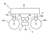
- FIG. 1 is a schematic configuration diagram of a suspension device according to an embodiment applied to a motorcycle.
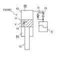
- FIG. 2 is a schematic view of a front wheel side shock absorber and a rear wheel side shock absorber of the suspension device according to the embodiment.
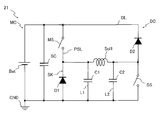
- FIG. 3 is a diagram showing a driving circuit for the solenoid valve on the front wheel side.
- FIG. 4 is a diagram showing a drive circuit for the solenoid valve on the rear wheel side.
- FIG. 5 is a diagram showing the transition of the current flowing through the solenoid supplied with current from the drive circuit of the solenoid valve on the rear wheel side.
- FIG. 6 is a diagram for explaining the operation of the drive circuit for the solenoid valve on the front wheel side when the solenoid is demagnetized.
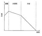
- FIG. 7 is a diagram showing a transition of a current flowing through a solenoid supplied with a current from a driving circuit for the solenoid valve on the front wheel side.
- the suspension device S includes a front wheel-side buffer capable of adjusting a damping force interposed between a vehicle body B and a front wheel FW of a two-wheeled vehicle M serving as a saddle-riding vehicle.
- a control device C as a suspension control device.
- the straddle vehicle is a two-wheeled vehicle M, but it may be a vehicle on which a passenger rides on a saddle, and may be a three-wheeled vehicle or a four-wheeled buggy.
- the front wheel side shock absorber FD and the rear wheel side shock absorber RD are slidably inserted into the cylinder 10 and the cylinder 10.
- a piston 11 that is divided into an extension side chamber R1 and a pressure side chamber R2 filled with liquid, a piston rod 12 that is also movably inserted into the cylinder 10 and connected to the piston 11, and a pressure side chamber R2 inside.
- a tank 13 having a reservoir R communicated therewith, an attenuation passage 14 that communicates the extension side chamber R1 and the pressure side chamber R2, a discharge passage 15 that provides resistance to the flow of liquid from the pressure side chamber R2 toward the reservoir R, and A suction passage 16 that allows only the flow of liquid toward the pressure side chamber R2 and an electromagnetic valve V that is provided in the attenuation passage 14 and adjusts the damping force are provided.
- the extension side chamber R1 and the pressure side chamber R2 are filled with liquid, and the reservoir R is filled with gas and liquid. In addition to hydraulic oil, other liquids such as water and aqueous solutions can be used as the liquid.
- the front wheel side shock absorber FD is not shown, but is hollow and expandable and is accommodated in a telescopic front fork in which the front wheel FW is suspended from the vehicle body B. It is inserted between B.
- the front fork is connected to a handle (not shown) of the two-wheeled vehicle M, and the front wheel FW can be steered by a rider's handle operation.
- the rear wheel side shock absorber RD is interposed between the vehicle body B and an arm that supports the rear wheel RW in a swingable manner with respect to the vehicle body B, although not shown.
- the front wheel side shock absorber FD and the rear wheel side shock absorber RD connect the tip of the piston rod 12 to the front wheel FW and the rear wheel RW of the two-wheeled vehicle M, and connect the cylinder 10 to the vehicle body B of the two-wheeled vehicle. Is installed.
- the gas and liquid in the reservoir R are partitioned by an elastic partition wall or a sliding partition wall, the front wheel side shock absorber FD and the rear wheel side shock absorber RD are turned upside down from FIG. May be installed on the motorcycle M.
- the electromagnetic valve V is, for example, an electromagnetic valve that drives the valve element with a solenoid, and adjusts the valve element position according to the amount of current supplied to change the flow path area, thereby flowing through the attenuation passage 14. The resistance given to the liquid is changed.
- the electromagnetic valve V may be a variable throttle that can adjust the flow path area in this way, or may be a pressure regulating valve that can adjust the valve opening pressure.
- the liquid moves from the expansion side chamber R1 to be compressed to the pressure side chamber R2 to be expanded through the attenuation passage 14.
- the electromagnetic valve V gives resistance to the flow of the liquid
- a differential pressure is generated between the extension side chamber R1 and the pressure side chamber R2.
- the front wheel side shock absorber FD and the rear wheel side shock absorber RD exhibit an extension side damping force that suppresses the extension operation according to the differential pressure. Note that liquid is supplied from the reservoir R through the suction passage 16 into the expanded pressure side chamber R2, and volume compensation of the piston rod 12 that retreats from the cylinder 10 is performed. Since the differential pressure between the extension side chamber R1 and the pressure side chamber R2 can be adjusted by the electromagnetic valve V, the damping force generated when the front wheel side shock absorber FD and the rear wheel side shock absorber RD are extended can be adjusted by the electromagnetic valve V.
- the liquid moves from the compression side chamber R2 to be compressed to the expansion side chamber R1 that is expanded via the attenuation passage 14. Further, since the piston rod 12 enters the cylinder 10, the excess liquid in the cylinder 10 is discharged from the pressure side chamber R ⁇ b> 2 to the reservoir R through the discharge passage 15. In this way, the liquid corresponding to the volume that has entered the cylinder 10 of the piston rod 12 is discharged from the cylinder 10 to the reservoir R, and the volume of the penetration of the piston rod 12 into the cylinder 10 is compensated.
- the discharge passage 15 and the electromagnetic valve V provide resistance to the movement of the liquid, so that the pressure in the cylinder 10 increases and the pressure side chamber A differential pressure is generated between R2 and the extension side chamber R1. Therefore, when the contraction operation is performed, the front wheel side shock absorber FD and the rear wheel side shock absorber RD are pressure sides that suppress the contraction operation according to the pressure increase in the cylinder 10 and the differential pressure between the compression side chamber R2 and the expansion side chamber R1. Demonstrates damping force.
- the damping force generated during the contraction operation of the front wheel side shock absorber FD and the rear wheel side shock absorber RD can be adjusted by the electromagnetic valve V.
- the front wheel side shock absorber FD and the rear wheel side shock absorber RD are not limited to the above-described configuration, and in the case of a magnetic viscous buffer using a working fluid as a magnetic viscous fluid, the damping passage 14 is turned on when energized instead of the solenoid valve V. What is necessary is just to provide the coil which makes a magnetic field act on.
- the control device C obtains a target value of the damping force to be exerted on the front wheel side shock absorber FD and the rear wheel side shock absorber RD, and each electromagnetic wave in the front wheel side shock absorber FD and the rear wheel side shock absorber RD.
- the control unit 20 generates a current command for instructing the amount of current to be supplied to the valve V, and driving circuits 21 and 22 that supply current to the solenoids of the solenoid valves V in accordance with the current command.
- the control unit 20 monitors the attitude of the vehicle body B to reduce the pitching and squatting of the two-wheeled vehicle M and to suppress the vibration of the vehicle body B, so that the front wheel side buffer FD and the rear wheel side buffer RD.
- the damping force that should be exhibited is obtained as a target value.
- a gyro sensor or an acceleration sensor installed in the vehicle body B, or a stroke sensor that detects expansion / contraction displacement of the front and rear shock absorbers FD and RD may be used.
- the control unit 20 determines the amount of current to be supplied to each electromagnetic valve V of the front wheel side shock absorber FD and the rear wheel side shock absorber RD from the target value and generates a current command.
- the control unit 20 knows in advance the relationship between the amount of current and the damping force exhibited by the front wheel side shock absorber FD and the rear wheel side shock absorber RD, and becomes the target damping force.
- the current command may be generated by obtaining the current amount from the value of.
- the drive circuit 21 for driving the front-wheel side electromagnetic valve V that is, the electromagnetic valve V in the front-wheel side shock absorber FD
- the drive circuit 22 for driving the solenoid valve V on the rear wheel side that is, the solenoid valve V in the rear wheel side shock absorber RD
- the front wheel side solenoid valve V drive circuit 21 has a circuit configuration in which the demagnetization circuit DC is added to the circuit configuration of the rear wheel side solenoid valve V drive circuit 22. Therefore, first, the drive circuit 22 that drives the rear wheel side solenoid valve V including only the main circuit MC will be described in detail.
- the drive circuit 22 for the rear-wheel side solenoid valve V includes only a main circuit MC that supplies power to the solenoid Sol2 in order to PWM-drive the rear-wheel side solenoid valve V.
- the main circuit MC is provided between the solenoid Sol2 and the power supply Bat in the middle of the power supply line PSL and the power supply line PSL that connects one end of the solenoid Sol2 to the power supply Bat and grounds the other end to the ground GND.
- a diode D1 interposed between the main switch MS composed of an N-channel MOSFET, the main switch MS of the power supply line PSL, the solenoid Sol2, and the ground GND with the direction from the ground side to the power supply side as the forward direction.
- a first line L1 and a second line L2 that connect between both sides of the solenoid Sol2 of the power supply line PSL and the ground GND, and a first noise removal intervening in the first line L1.
- the drive circuit 22 includes a switch control unit (not shown) that receives an input of a control command from the control unit 20 and controls opening and closing of the main switch MS.
- the main circuit MC configured in this way can supply power from the power source Bat to the solenoid Sol2 when the main switch MS is closed, and the power supply from the power source Bat to the solenoid Sol2 is cut off when the main switch MS is opened.
- the main switch MS is opened when the main switch MS is closed and power is supplied to the solenoid Sol2
- a counter electromotive force is generated in the solenoid Sol2
- the surge killer SK functions to prevent an excessive surge from being generated in the solenoid Sol2.
- the current flowing through the solenoid Sol2 gradually drops. Specifically, when the main switch MS is turned on and the solenoid Sol2 is energized, as shown in FIG.
- the solenoid Sol2 is applied to increase the current, and when the main switch MS is turned off, the current flowing through the solenoid Sol2 gradually increases. Therefore, the current may be adjusted by opening and closing the main switch MS according to the current desired to flow through the solenoid Sol2.
- the drive circuit 22 applies a voltage to the solenoid Sol2 so that the current value specified by the current command is applied to the solenoid Sol2.
- the drive circuit 22 sets the ON duty ratio of the main switch MS so that the current flowing through the solenoid Sol2 conforms to the current command. Open and close the switch MS. In this way, the drive circuit 22 opens and closes the main switch MS to adjust the voltage applied to the solenoid Sol2 and PWM drives the solenoid valve V. Since the voltage sent from the power source Bat to the main switch MS side is smoothed by the smoothing capacitor SC, the drive circuit 22 can accurately control the voltage applied to the solenoid Sol2 even if the output voltage of the power source Bat fluctuates.
- the drive circuit 21 for the solenoid valve V on the front wheel side demagnetizes the solenoid Sol1 in addition to the main circuit MC that supplies power to the solenoid Sol1 for PWM driving the solenoid valve V on the front wheel side. And a degaussing circuit DC.
- the main circuit MC has the same configuration as the main circuit MC in the drive circuit 22 of the solenoid valve V on the rear wheel side.
- the demagnetization circuit DC is in the middle of the power supply line PSL in the main circuit MC and in the middle of the power supply line PSL and the demagnetization switch DS composed of an N-channel MOSFET provided between the solenoid Sol1 and the ground GND.
- a demagnetization line DL that connects between the main switch MS and the power source Bat, and between the solenoid Sol1 and the demagnetization switch DS, and a demagnetization provided in the middle of the demagnetization line DL with the direction from the ground side toward the power source side as a forward direction.
- a smoothing capacitor SC interposed between the power supply Bat and the surge killer SK and the ground GND.
- the drive circuit 21 includes a switch control unit that receives a control command from the control unit 20 and controls opening and closing of the main switch MS and the demagnetization switch DS.
- the demagnetization switch DS causes the solenoid Sol1 to be installed on the ground GND in the closed state. Therefore, the drive circuit 21 can adjust the voltage applied to the solenoid Sol1 in the same manner as the drive circuit 22 by opening and closing the main switch MS provided in the power supply line PSL when the degaussing switch DS is turned on. Therefore, when adjusting the current value of the solenoid Sol1 to the current value specified by the current command input from the control unit 20, the drive circuit 21 basically maintains the demagnetization switch DS in the ON state.
- the drive circuit 21 sets the ON duty ratio of the main switch MS so that the current flowing through the solenoid Sol1 conforms to the current command. To open and close the main switch MS. In this way, the drive circuit 21 opens and closes the main switch MS to adjust the voltage applied to the solenoid Sol1, and PWM drives the solenoid valve V.
- the main switch MS is turned off to stop the power supply from the power source Bat to the solenoid Sol1, and the demagnetization switch DS is also turned off to turn the solenoid Sol1 downstream. And ground GND are disconnected.
- the left end of the solenoid Sol1 in FIG. 6 is connected to the ground GND via the diode D1 in the surge killer SK, and the right end of the solenoid Sol1 in FIG. 6 is connected to the power source Bat via the demagnetization line DL.
- the route is valid.
- the main switch MS when the main switch MS is turned off, the voltage applied to the solenoid Sol1 suddenly becomes zero and a back electromotive force is generated in the solenoid Sol1, and the current becomes effective as shown by the arrow in FIG. Flows in the direction from the ground GND to the power source Bat.
- the power source Bat opposes the back electromotive force of the solenoid Sol1 and reversely excites the solenoid Sol1, so that the current flowing through the solenoid Sol1 disappears quickly and the solenoid Sol1 is quickly demagnetized.
- the solenoid Val V on the front wheel side quickly returns to the position where the solenoid Sol1 is in a non-excited state.
- the demagnetization switch DS is also turned off together with the main switch MS being turned off. May be demagnetized.
- the solenoid Sol1 is applied to increase the current, and the demagnetizing switch DS is turned on.
- the main switch MS is turned off, the current flowing through the solenoid Sol1 gradually decreases.
- both the main switch MS and the degaussing switch DS are turned off, the current flowing through the solenoid Sol1 decreases rapidly.
- the degaussing switch DS functions as a switch for switching the degaussing circuit DC between valid and invalid.
- the control unit 20 includes the drive circuits 21 and 22 described above, the current of the solenoid Sol1 of the solenoid valve V on the front wheel side drops more quickly than the solenoid Sol2 of the solenoid valve V on the rear wheel side. Therefore, in the suspension device S of the present example, the front wheel side shock absorber FD has higher responsiveness than the rear wheel side shock absorber RD with respect to the response of the damping force adjustment.
- the front wheel side shock absorber FD is required to adjust the damping force with high response, but the rear wheel side shock absorber RD has about the same amount as the front wheel side shock absorber FD.
- the response in adjusting the damping force is not required. Therefore, like the suspension device S of this example, the front wheel side shock absorber FD can be adjusted with a high response damping force, and the rear wheel side shock absorber RD can be adjusted to have a lower response than the front wheel side shock absorber FD when adjusting the damping force. Riding comfort in the motorcycle M can be ensured.
- the suspension device S of this example is compared with the conventional suspension device in which the response of the damping force adjustment of the rear wheel side shock absorber is equivalent to that of the front wheel side shock absorber with reference to the front wheel side shock absorber. Since the responsiveness of the damping force adjustment of the rear wheel side shock absorber RD can be lowered, the cost is reduced correspondingly and the cost is reduced. Therefore, according to the suspension device S of the present invention, it is possible to reduce the cost while ensuring the riding comfort in the two-wheeled vehicle (saddle riding vehicle) M.
- the front wheel side damper FD for adjusting the damping force in the front wheel side shock absorber FD interposed between the vehicle body B and the front wheel FW in the two-wheeled vehicle (saddle vehicle) M is arranged.
- a demagnetizing circuit DC for demagnetizing the solenoid Sol1 in the solenoid valve V on the front wheel side only in the driving circuit 21 on the front wheel side.
- the drive circuit 22 for driving the electromagnetic valve V for adjusting the damping force of the rear wheel side shock absorber RD is used for adjusting the damping force of the front wheel side shock absorber FD.
- the drive circuit 21 that drives the electromagnetic valve V can be made to have a difference in responsiveness as an inexpensive circuit configuration. Therefore, in the control device (suspension control device) C of this example, it is possible to reduce the cost by providing a difference in the responsiveness in the damping force adjustment between the front wheel side shock absorber FD and the rear wheel side shock absorber RD.
- both the front wheel-side shock absorber FD and the rear wheel-side shock absorber RD are shock absorbers using the above-described magnetorheological fluid
- the magnetic field applied to the magnetorheological fluid is adjusted by the amount of current supplied to the coil. . Therefore, while the driving circuit 21 having the demagnetizing circuit DC is used for adjusting the damping force of the front wheel side shock absorber FD, the driving circuit 22 without the demagnetizing circuit DC is used for adjusting the damping force of the rear wheel side buffer RD.
- the suspension control device is inexpensive, the cost of the suspension device S as a whole can be reduced.
- the driving circuit 21 on the front wheel side has two switches, a main switch MS that adjusts the applied voltage of the solenoid Sol1 and a degaussing switch DS that switches between deactivation and deactivation of the demagnetization circuit DC. Since the rear wheel side drive circuit 22 has only a main switch MS for adjusting the voltage applied to the solenoid Sol2 with respect to the switch, the rear wheel side drive circuit 22 is less expensive than the front wheel side drive circuit 21. it can.
- the hardware of the front wheel side shock absorber FD and the rear wheel side shock absorber RD may have different responsiveness to reduce the cost. That is, the front wheel-side shock absorber FD has a structure corresponding to a high response with respect to the electromagnetic valve V for adjusting the damping force, and the rear wheel-side shock absorber RD has a structure using an inexpensive electromagnetic valve V with low responsiveness. The cost of the entire device S may be reduced. Furthermore, it is possible to reduce the cost of the suspension device S as a whole by making the hydraulic circuit configurations of the front wheel side shock absorber FD and the rear wheel side shock absorber RD different to give different responsiveness.
- the valve opening pressure is decreased and de-energized. If the valve opening pressure is sometimes set to the maximum, the front wheel side shock absorber FD can increase the damping force with high responsiveness. As described above, when the damping force is increased when the front wheel side shock absorber FD is not energized, the front wheel side shock absorber FD quickly increases the damping force when the current cannot be supplied to the solenoid Sol1. The time for the state becomes shorter.
- the damping force of the front and rear shock absorbers FD and RD is increased when the damping force is increased when not energized, as in the front wheel side shock absorber FD. Even during a failure, the damping force is exerted so that the ride comfort in the vehicle is not significantly deteriorated.
- the valve opening pressure is increased and the current is not supplied. If the valve opening pressure is sometimes set to the minimum, the front wheel side shock absorber FD can reduce the damping force with high responsiveness. In this way, when the front wheel side shock absorber FD reduces the damping force when not energized, the damping force of the front wheel side shock absorber FD is calculated based on the Karnop law when the vehicle body B is vibrated due to the exertion of the damping force. Since it can be quickly reduced, it is optimal for control based on the Karnop law.
- the suspension device S is optimal for the two-wheeled vehicle M.
- the front wheel side shock absorber FD and the rear wheel side shock absorber RD both allow adjustment of the damping force during expansion and contraction with a single electromagnetic valve V, but the expansion side chamber R1.
- An attenuation passage 14 is constituted by an extension side passage that allows only the flow of liquid from the pressure side chamber R2 to the pressure side chamber R2, and a pressure side passage that allows only the flow of the liquid from the pressure side chamber R2 to the extension side chamber R1.
- An electromagnetic valve V may be provided in each pressure side passage.
- the front wheel side shock absorber FD and the rear wheel side shock absorber RD are configured in this way, two electromagnetic valves, an electromagnetic valve V that exhibits a damping force when extended and an electromagnetic valve V that exhibits a damping force when contracted. Since V is provided in the front wheel side shock absorber FD and the rear wheel side shock absorber RD, the front wheel side drive circuit 21 and the rear wheel side drive circuit 22 may be provided in the control device C.
- the damping passage 14 is composed of an extension side passage and a pressure side passage and an extension side damping valve for opening and closing the extension side passage and a pressure side damping valve for opening and closing the pressure side passage are provided
- the extension side damping valve, the pressure side damping valve, The damping force may be adjusted by adjusting the pressure of the back pressure chamber that urges the valve in the valve closing direction with the internal pressure with the electromagnetic valve V.
Landscapes
- Engineering & Computer Science (AREA)
- Mechanical Engineering (AREA)
- Axle Suspensions And Sidecars For Cycles (AREA)
- Vehicle Body Suspensions (AREA)
- Vibration Prevention Devices (AREA)
- Fluid-Damping Devices (AREA)
Abstract
本発明のサスペンション装置(S)は、減衰力調整可能であって鞍乗車両における車体(B)と前輪(FW)との間に介装される前輪側緩衝器(FD)と、減衰力調整可能であって車体(B)と後輪(RW)との間に介装される後輪側緩衝器(RD)と、前輪側緩衝器(FD)と後輪側緩衝器(RD)の減衰力を制御する制御装置(C)とを備え、前輪側緩衝器(FD)の減衰力調整における応答性を後輪側緩衝器(RD)における減衰力調整における応答性よりも高応答とした。
Description
本発明は、サスペンション装置およびサスペンション制御装置に関する。
車両の車体と前後輪との間に減衰力可変の前輪側緩衝器と後輪側緩衝器を備えたサスペンション装置にあっては、たとえば、JP2017-030577Aに開示されているように、車体の姿勢変化に対応して前輪側緩衝器と後輪側緩衝器の減衰力を制御する制御装置を備えている(たとえば、特許文献1参照)。
このようなサスペンション装置では、前輪側緩衝器および後輪側緩衝器がともに同じ構成とされており、制御装置内の前輪側緩衝器および後輪側緩衝器に対応する回路構成もそれぞれ同様の構成を備えている。
ここで、鞍乗車両の場合、前輪側緩衝器の方が後輪側緩衝器に比較してストローク長を長くしており、前輪側緩衝器の減衰力調整の応答性が低いと、前輪側緩衝器の減衰力を最適とするまでに時間が掛かり、搭乗者の搭乗姿勢を乱して乗心地を悪化する場合がある。このように、前輪側緩衝器には減衰力調整に高い応答性が求められるが、従来のサスペンション装置では、後輪側緩衝器も前輪側緩衝器と同じ応答性を発揮できるものが使用されている。
よって、従来のサスペンション装置或いはサスペンション装置に利用されるサスペンション制御装置は、非常に高価であってコストの低減が要望されている。
そこで、本発明は、鞍乗車両における乗心地を確保しつつもコストを低減できるサスペンション装置およびサスペンション制御装置の提供を目的としている。
上記目的を達成するために、本発明のサスペンション装置は、減衰力調整可能であって鞍乗車両における車体と前輪との間に介装される前輪側緩衝器と、減衰力調整可能であって車体と後輪との間に介装される後輪側緩衝器と、前輪側緩衝器と後輪側緩衝器の減衰力を制御する制御装置とを備え、前輪側緩衝器の減衰力調整における応答性を後輪側緩衝器における減衰力調整における応答性よりも高応答とした。
また、上記目的を達成するために、本発明のサスペンション制御装置は、鞍乗車両における車体と前輪との間に介装される前輪側緩衝器における減衰力を調整する前輪側の電磁弁を駆動する前輪側の駆動回路と、車体と後輪との間に介装される後輪側緩衝器における減衰力を調整する後輪側の電磁弁を駆動する後輪側の駆動回路とを備え、前輪側の駆動回路にのみ前輪側の電磁弁におけるソレノイドを消磁させる消磁回路を設けている。
以下、図に示した実施の形態に基づき、本発明を説明する。図1に示すように、一実施の形態におけるサスペンション装置Sは、この例では、鞍乗車両としての二輪車Mの車体Bと前輪FWとの間に介装される減衰力調整可能な前輪側緩衝器FDと、車体Bと後輪RWとの間に介装される減衰力調整可能な後輪側緩衝器RDと、これら前輪側緩衝器FDと後輪側緩衝器RDにおける減衰力を制御するサスペンション制御装置としての制御装置Cとを備えている。本例では、鞍乗車両は、二輪車Mとされているが、搭乗者がサドルに跨って乗車する車両であればよく、三輪車や四輪バギーであってもよい。
以下、各部材について詳細に説明すると、前輪側緩衝器FDおよび後輪側緩衝器RDは、図2に示すように、たとえば、シリンダ10と、シリンダ10内に摺動自在に挿入されてシリンダ10内に液体が充填される伸側室R1と圧側室R2とに区画するピストン11と、同じくシリンダ10内に移動自在に挿入されてピストン11に連結されるピストンロッド12と、内部に圧側室R2に連通されるリザーバRを備えるタンク13と、伸側室R1と圧側室R2とを連通する減衰通路14と、圧側室R2からリザーバRへ向かう液体の流れに抵抗を与える排出通路15と、リザーバRから圧側室R2へ向かう液体の流れのみを許容する吸込通路16と、減衰通路14に設けられて減衰力調整を行う電磁弁Vとを備えている。そして、伸側室R1と圧側室R2には、液体が充填され、リザーバRには、気体と液体とが充填されている。液体には、作動油のほか、水、水溶液等の他の液体も利用できる。
また、本例では、前輪側緩衝器FDは、図示はしないが、内部が中空で伸縮可能であって車体Bに前輪FWを懸架するテレスコピック型のフロントフォーク内に収容されて、前輪FWと車体Bとの間に介装される。前記のフロントフォークは、二輪車Mの図示しないハンドルに連結されており、搭乗者のハンドル操作によって前輪FWの操舵が可能となっている。さらに、本例では、後輪側緩衝器RDは、図示はしないが、車体Bとこの車体Bに対して後輪RWを揺動可能に支持するアームとの間に介装される。本例では、前輪側緩衝器FDおよび後輪側緩衝器RDは、ピストンロッド12の先端を二輪車Mの前輪FWおよび後輪RWに連結し、シリンダ10を二輪車の車体Bに連結して二輪車Mに設置されている。なお、リザーバR内の気体と液体とが、弾性隔壁や摺動隔壁などによって仕切られている場合には、前輪側緩衝器FDおよび後輪側緩衝器RDは、図2とは天地逆向きにして二輪車Mに設置されてもよい。
電磁弁Vは、たとえば、ソレノイドで弁体を駆動する電磁弁とされ、供給する電流量によって弁体位置を調整して流路面積を変化させるようになっており、これによって減衰通路14を流れる液体へ与える抵抗を変化させる。電磁弁Vは、このように流路面積を調整できる可変絞りとされてもよいし、開弁圧を調整できる圧力調整弁とされてもよい。
そして、この前輪側緩衝器FDおよび後輪側緩衝器RDが伸長作動する場合、圧縮される伸側室R1から減衰通路14を介して拡大される圧側室R2へ液体が移動する。その際に、液体が電磁弁Vを通過し、電磁弁Vが液体の流れに抵抗を与えるので、伸側室R1と圧側室R2とに差圧が生じる。前輪側緩衝器FDおよび後輪側緩衝器RDは、この差圧に応じて伸長作動を抑制する伸側減衰力を発揮する。なお、拡大される圧側室R2内には、リザーバRから吸込通路16を介して液体が供給され、シリンダ10内から退出するピストンロッド12の体積補償がなされる。伸側室R1と圧側室R2との差圧は、電磁弁Vによって調節できるので、前輪側緩衝器FDおよび後輪側緩衝器RDが伸長作動時に発生する減衰力を電磁弁Vにより調節できる。
反対に、前輪側緩衝器FDおよび後輪側緩衝器RDは、収縮作動する場合、圧縮される圧側室R2から減衰通路14を介して拡大される伸側室R1へ液体が移動する。また、シリンダ10内にピストンロッド12が侵入するのでシリンダ10内で過剰となった液体が排出通路15を介して圧側室R2からリザーバRへ排出される。このように、ピストンロッド12のシリンダ10内へ侵入した体積相当の液体がシリンダ10からリザーバRへ排出されて、ピストンロッド12のシリンダ10内への侵入体積の補償がなされる。そして、前輪側緩衝器FDおよび後輪側緩衝器RDが収縮作動する場合、液体の移動に対して排出通路15および電磁弁Vが抵抗を与えるので、シリンダ10内の圧力が上昇するとともに圧側室R2と伸側室R1に差圧が生じる。よって、収縮作動する場合、前輪側緩衝器FDおよび後輪側緩衝器RDは、シリンダ10内の圧力上昇と、圧側室R2と伸側室R1との差圧に応じて、収縮作動を抑制する圧側減衰力を発揮する。圧側室R2と伸側室R1との差圧は、電磁弁Vによって調節できるので、前輪側緩衝器FDおよび後輪側緩衝器RDが収縮作動時に発生する減衰力を電磁弁Vにより調節できる。
なお、前輪側緩衝器FDおよび後輪側緩衝器RDは、前記構成に限られず、作動液体を磁気粘性流体とした磁気粘性緩衝器とされる場合、電磁弁Vの代わりに通電時に減衰通路14に磁界を作用させるコイルを設ければよい。
制御装置Cは、図1に示すように、前輪側緩衝器FDおよび後輪側緩衝器RDに発揮させる減衰力の目標値を求めて前輪側緩衝器FDおよび後輪側緩衝器RDにおける各電磁弁Vへ与える電流量を指示する電流指令を生成する制御部20と、各電磁弁Vのソレノイドへ電流指令通りに電流供給する駆動回路21,22とを備えて構成されている。
制御部20は、たとえば、車体Bの姿勢を監視して、二輪車Mのピッチングやスクウォートを低減したり、車体Bの振動を抑制したりするために前輪側緩衝器FDおよび後輪側緩衝器RDが発揮すべき減衰力を目標値として求める。車体Bの姿勢の監視については、車体Bに設置されるジャイロセンサや加速度センサ、前後の緩衝器FD,RDの伸縮変位を検出するストロークセンサを利用すればよい。
また、制御部20は、減衰力の目標値を求めると、目標値から前輪側緩衝器FDおよび後輪側緩衝器RDの各電磁弁Vへ供給する電流量を求めて電流指令を生成する。電流指令の生成にあたっては、たとえば、制御部20は、予め、電流量と前輪側緩衝器FDおよび後輪側緩衝器RDが発揮する減衰力との関係を把握しており、目標となる減衰力の値から電流量を求めて電流指令を生成すればよい。
前輪側の電磁弁V、つまり、前輪側緩衝器FDにおける電磁弁Vを駆動する駆動回路21は、図3に示すように、前輪側の電磁弁VのソレノイドSol1をPWM駆動する主回路MCと、ソレノイドSol1を消磁させる消磁回路DCとを備えている。他方、後輪側の電磁弁V、つまり、後輪側緩衝器RDにおける電磁弁Vを駆動する駆動回路22は、図4に示すように、後輪側の電磁弁VのソレノイドSol2をPWM駆動する主回路MCのみを備える。つまり、前輪側の電磁弁Vの駆動回路21は、後輪側の電磁弁Vの駆動回路22の回路構成に消磁回路DCを加えた回路構成とされている。よって、まず、主回路MCのみを備える後輪側の電磁弁Vを駆動する駆動回路22から詳細に説明する。
図4に示すように、後輪側の電磁弁Vの駆動回路22は、後輪側の電磁弁VをPWM駆動するためにソレノイドSol2へ電力供給する主回路MCのみを備えている。主回路MCは、ソレノイドSol2の一端を電源Batへ接続するとともに他端をグランドGNDへ接地させる電力供給ラインPSLと、電力供給ラインPSLの途中であってソレノイドSol2と電源Batとの間に設けたNチャンネルのMOSFETからなるメインスイッチMSと、電力供給ラインPSLのメインスイッチMSとソレノイドSol2との間とグランドGNDとの間にグランド側から電源側へ向かう方向を順方向として介装されるダイオードD1を有するサージキラーSKと、電力供給ラインPSLのソレノイドSol2の両側とグランドGNDとの間を接続する第一ラインL1と第二ラインL2と、第一ラインL1に介装されるノイズ除去用の第一コンデンサC1と、第二ラインL2に介装されるノイズ除去用の第二コンデンサC2と、電源BatとサージキラーSKとの間とグランドGNDとの間に介装された平滑コンデンサSCとを備えて構成されている。また、駆動回路22は、図示しないが制御部20から制御指令の入力を受けてメインスイッチMSを開閉制御するスイッチ制御部を備えている。
このように構成された主回路MCは、メインスイッチMSを閉じると電源BatからソレノイドSol2へ電力供給でき、メインスイッチMSを開くと電源BatからソレノイドSol2への通電が絶たれる。メインスイッチMSが閉じておりソレノイドSol2へ電力供給されている状態からメインスイッチMSを開くと、ソレノイドSol2に逆起電力が生じるがサージキラーSKが機能してソレノイドSol2における過大なサージの発生が防止され、ソレノイドSol2に流れる電流は緩やかに降下する。具体的には、メインスイッチMSをオンしてソレノイドSol2へ通電すると、図5に示すように、ソレノイドSol2が印加されて電流が増加し、メインスイッチMSをオフするとソレノイドSol2に流れる電流が徐々に減少するので、ソレノイドSol2に流したい電流に応じてメインスイッチMSを開閉して電流調整すればよい。
したがって、駆動回路22は、制御部20から電流指令が与えられると、ソレノイドSol2に電流指令が指定する電流値になるようにソレノイドSol2に電圧を印加する。電流指令通りの電流値になるようにソレノイドSol2の印加電圧を調節するため、駆動回路22は、ソレノイドSol2に流れる電流が電流指令通りになるようにメインスイッチMSのONデューティ比を設定してメインスイッチMSを開閉する。このように駆動回路22は、メインスイッチMSを開閉してソレノイドSol2の印加電圧を調節して電磁弁VをPWM駆動する。なお、電源BatからメインスイッチMS側へ送られる電圧が平滑コンデンサSCにより平滑化されるので、駆動回路22は、電源Batの出力電圧が変動してもソレノイドSol2の印加電圧を精度よく制御できる。
他方、前輪側の電磁弁Vの駆動回路21は、図3に示すように、前輪側の電磁弁VをPWM駆動するためにソレノイドSol1へ電力供給する主回路MCに加えて、ソレノイドSol1を消磁させる消磁回路DCとを備えている。主回路MCは、後輪側の電磁弁Vの駆動回路22における主回路MCと同様の構成とされている。
消磁回路DCは、主回路MCにおける電力供給ラインPSLの途中であってソレノイドSol1とグランドGNDとの間に設けたNチャンネルのMOSFETからなる消磁用スイッチDSと、電力供給ラインPSLの途中であってメインスイッチMSと電源Batとの間とソレノイドSol1と消磁用スイッチDSとの間とを接続する消磁ラインDLと、グランド側から電源側へ向かう方向を順方向として消磁ラインDLの途中に設けられる消磁用ダイオードD2と、電源BatとサージキラーSKとの間とグランドGNDとの間に介装された平滑コンデンサSCとを備えて構成されている。また、駆動回路21は、図示しないが制御部20から制御指令の入力を受けてメインスイッチMSおよび消磁用スイッチDSを開閉制御するスイッチ制御部を備えている。
消磁用スイッチDSは、閉じた状態ではソレノイドSol1をグランドGNDへ設置させる。よって、駆動回路21は、消磁用スイッチDSをON状態にしておくと、電力供給ラインPSLに設けたメインスイッチMSの開閉によって、ソレノイドSol1の印加電圧を駆動回路22と同様に調節できる。したがって、駆動回路21は、ソレノイドSol1の電流値を制御部20から入力される電流指令が指定する電流値に調節する場合には、基本的には、消磁用スイッチDSをON状態に維持する。そして、電流指令通りの電流値になるようにソレノイドSol1の印加電圧を調節するため、駆動回路21は、ソレノイドSol1に流れる電流が電流指令通りになるようにメインスイッチMSのONデューティ比を設定してメインスイッチMSを開閉する。このように駆動回路21は、メインスイッチMSを開閉してソレノイドSol1の印加電圧を調節して電磁弁VをPWM駆動する。
これに対して、ソレノイドSol1を急速に消磁したい場合には、メインスイッチMSをオフして電源BatからソレノイドSol1への電力供給を停止させるとともに消磁用スイッチDSもオフして下流側でのソレノイドSol1とグランドGNDとの接続を断つ。
すると、図6に示すように、ソレノイドSol1の図6中左端がサージキラーSKにおけるダイオードD1を介してグランドGNDに接続され、ソレノイドSol1の図6中右端が消磁ラインDLを介して電源Batに接続されるルートが有効となる。この状況では、メインスイッチMSのオフによってソレノイドSol1への印加電圧が急激に0となりソレノイドSol1に逆起電力が生じて、電流は、図6中の矢印で示したように、前述の有効となった回路中をグランドGNDから電源Batへ向う方向に流れる。そして、この状態では、電源BatがソレノイドSol1の逆起電力に対向してソレノイドSol1を逆励磁するので、ソレノイドSol1に流れる電流は速やかに消滅してソレノイドSol1は速やかに消磁される。この様にソレノイドSol1が速やかに消磁されると、前輪側の電磁弁Vは、ソレノイドSol1が非励磁の状態に採る位置へ速やかに復帰する。なお、メインスイッチMSの開閉によるソレノイドSol1の電流調整の際であっても、ソレノイドSol1の電流を急激に下げる必要がある場合にはメインスイッチMSのオフとともに消磁用スイッチDSもオフさせてソレノイドSol1を消磁させてもよい。
具体的には、メインスイッチMSと消磁用スイッチDSを共にオンしてソレノイドSol1へ通電すると、図7に示すように、ソレノイドSol1が印加されて電流が増加し、消磁用スイッチDSをオンにしたままメインスイッチMSをオフするとソレノイドSol1に流れる電流が徐々に減少し、メインスイッチMSと消磁用スイッチDSを共にオフするとソレノイドSol1に流れる電流は速やかに減少する。このように、消磁用スイッチDSは、消磁回路DCの有効と無効を切換えるスイッチとして機能する。
このように制御部20が前述の駆動回路21,22を備えているため、後輪側の電磁弁VのソレノイドSol2よりも前輪側の電磁弁VのソレノイドSol1の方が速やかに電流降下する。よって、本例のサスペンション装置Sにあっては、減衰力調整の応答性に関して後輪側緩衝器RDに比較して前輪側緩衝器FDの方が高い応答性を備える。
ここで、鞍乗車両である二輪車Mの場合、前述のように、前輪側緩衝器FDには高応答の減衰力調整が求められるが、後輪側緩衝器RDには前輪側緩衝器FD程の減衰力調整における応答性は求められない。したがって、本例のサスペンション装置Sのように前輪側緩衝器FDについては高応答で減衰力調整を可能とし、後輪側緩衝器RDについて減衰力調整に際して前輪側緩衝器FDよりも低応答としても二輪車Mにおける乗心地を確保できる。
このように、本例のサスペンション装置Sは、前輪側緩衝器を基準として後輪側緩衝器の減衰力調整の応答性を前輪側緩衝器のそれと同等とする従来のサスペンション装置に比較して、後輪側緩衝器RDの減衰力調整の応答性を低下させ得るのでその分コストが低減されて安価となる。よって、本発明のサスペンション装置Sによれば、二輪車(鞍乗車両)Mにおける乗心地を確保しつつもコストを低減できるのである。
また、本例の制御装置(サスペンション制御装置)Cでは、二輪車(鞍乗車両)Mにおける車体Bと前輪FWとの間に介装される前輪側緩衝器FDにおける減衰力を調整する前輪側の電磁弁Vを駆動する前輪側の駆動回路21と、車体Bと後輪RWとの間に介装される後輪側緩衝器RDにおける減衰力を調整する後輪側の電磁弁Vを駆動する後輪側の駆動回路22とを備え、前輪側の駆動回路21にのみ前輪側の電磁弁VにおけるソレノイドSol1を消磁させる消磁回路DCを設けている。このように構成される制御装置(サスペンション制御装置)Cによれば、後輪側緩衝器RDの減衰力調整用の電磁弁Vを駆動する駆動回路22を前輪側緩衝器FDの減衰力調整用の電磁弁Vを駆動する駆動回路21に対して安価な回路構成として応答性に差異を持たせられる。よって、本例の制御装置(サスペンション制御装置)Cでは、前輪側緩衝器FDと後輪側緩衝器RDの減衰力調整における応答性に差異を設けてコストを低減できる。
なお、前輪側緩衝器FDと後輪側緩衝器RDの双方を前述した磁気粘性流体を利用した緩衝器とする場合、コイルへの通電量によって磁気粘性流体に作用させる磁界を調節するようになる。よって、前輪側緩衝器FDの減衰力調整に消磁回路DCを備えた駆動回路21を用いる一方、後輪側緩衝器RDの減衰力調整には、消磁回路DCを省略した駆動回路22を用いればよく、このようにすれば、サスペンション制御装置が安価となるので、サスペンション装置S全体としてもコスト低減が可能となる。
具体的に、本例では、前輪側の駆動回路21がスイッチに関し、ソレノイドSol1の印加電圧を調節するメインスイッチMSと消磁回路DCの有効と無効を切換える消磁用スイッチDSの二つのスイッチを有し、後輪側の駆動回路22がスイッチに関し、ソレノイドSol2の印加電圧を調節するメインスイッチMSのみを有しているので、後輪側の駆動回路22を前輪側の駆動回路21に対して安価にできる。
また、前輪側緩衝器FDと後輪側緩衝器RDのハードウェア自体で応答性に差異を持たせて、コストを低減させてもよい。つまり、前輪側緩衝器FDについては減衰力調整を行う電磁弁Vについて高応答に対応する構造とし、後輪側緩衝器RDについては応答性が低い安価な電磁弁Vを利用する構造として、サスペンション装置S全体のコストを低減してもよい。さらには、前輪側緩衝器FDと後輪側緩衝器RDの油圧回路構成を異なるものとして応答性に差異を持たせて、全体としてサスペンション装置Sのコスト低減を図ってもよい。
さらに、電磁弁VがソレノイドSol1に流れる電流量が大きくなると流路面積を大きくし非通電時に流路面積を最小とするか、ソレノイドSol1に流れる電流量が大きくなると開弁圧を小さくし非通電時に開弁圧を最大とするように設定されると、前輪側緩衝器FDでは応答性よく減衰力を高くできるようになる。このように前輪側緩衝器FDが非通電時に減衰力を高くする場合には、ソレノイドSol1へ電流供給できなくなる場合に前輪側緩衝器FDが速やかに減衰力を高くするので、フェール時に減衰力不足の状態となる時間が短縮される。なお、後輪側緩衝器RDにおける電磁弁Vについても、前輪側緩衝器FDと同様に、非通電時に減衰力を高くする場合には、前後の緩衝器FD,RDの減衰力が高くなるので、フェール時にも減衰力の発揮で車両における乗心地の著しい悪化を招かずに済む。
また、電磁弁VがソレノイドSol1に流れる電流量が大きくなると流路面積を小さくし非通電時に流路面積を最大とするか、ソレノイドSol1に流れる電流量が大きくなると開弁圧を大きくし非通電時に開弁圧を最小とするように設定されると、前輪側緩衝器FDでは応答性よく減衰力を低くできるようになる。このように前輪側緩衝器FDが非通電時に減衰力を低くする場合には、減衰力の発揮で車体Bを加振してしまう場合にカルノップ則に基づいて前輪側緩衝器FDの減衰力を速やかに低減できるので、カルノップ則に基づく制御に最適となる。
そして、ストローク長が長くなる前輪側緩衝器FDの減衰力調整を応答性よく行えるので、二輪車Mにおける搭乗者の搭乗姿勢に悪影響を与えずに済むので、サスペンション装置Sは、二輪車Mに最適となる。
なお、本例のサスペンション装置Sにおける前輪側緩衝器FDおよび後輪側緩衝器RDでは、共に単一の電磁弁Vで伸長時と収縮時の減衰力の調整と可能としているが、伸側室R1から圧側室R2へ向かう液体の流れのみを許容する伸側通路と、圧側室R2から伸側室R1へ向かう液体の流れのみを許容する圧側通路とで減衰通路14を構成して、伸側通路と圧側通路の各々に電磁弁Vを設ける構成としてもよい。このように前輪側緩衝器FDおよび後輪側緩衝器RDとが構成されると、伸長時に減衰力を発揮する電磁弁Vと、収縮時に減衰力を発揮する電磁弁Vとの二つの電磁弁Vが前輪側緩衝器FDおよび後輪側緩衝器RDに設けられるので、制御装置Cに前輪側の駆動回路21と後輪側の駆動回路22をそれぞれ二つずつ設けるようにすればよい。また、減衰通路14を伸側通路と圧側通路とで構成して、伸側通路を開閉する伸側減衰弁と圧側通路を開閉する圧側減衰弁を設ける場合、伸側減衰弁と圧側減衰弁とを内部圧力で閉弁方向に附勢する背圧室の圧力を電磁弁Vで調整して減衰力調整を行うようにしてもよい。
以上、本発明の好ましい実施の形態を詳細に説明したが、特許請求の範囲から逸脱しない限り、改造、変形及び変更が可能である。
本願は、2017年4月28日に日本国特許庁に出願された特願2017-089234に基づく優先権を主張し、この出願の全ての内容は参照により本明細書に組み込まれる。
Claims (5)
- 鞍乗車両のサスペンション装置であって、
減衰力調整可能であって鞍乗車両における車体と前輪との間に介装される前輪側緩衝器と、
減衰力調整可能であって前記鞍乗車両における前記車体と後輪との間に介装される後輪側緩衝器と、
前記前輪側緩衝器と前記後輪側緩衝器の減衰力を制御する制御装置とを備え、
前記前輪側緩衝器の減衰力調整における応答性を前記後輪側緩衝器における減衰力調整における応答性よりも高応答とした
鞍乗車両のサスペンション装置。 - 請求項1に記載の鞍乗車両のサスペンション装置であって、
前記前輪側緩衝器は、非通電時に減衰力を高くする
鞍乗車両のサスペンション装置。 - 請求項1に記載の鞍乗車両のサスペンション装置であって、
前記前輪側緩衝器は、非通電時に減衰力を低くする
鞍乗車両のサスペンション装置。 - サスペンション制御装置であって、
鞍乗車両における車体と前輪との間に介装される前輪側緩衝器における減衰力を調整する前輪側の電磁弁を駆動する前輪側の駆動回路と、
前記鞍乗車両における前記車体と後輪との間に介装される後輪側緩衝器における減衰力を調整する後輪側の電磁弁を駆動する後輪側の駆動回路とを備え、
前記前輪側の駆動回路にのみ前記前輪側の電磁弁におけるソレノイドを消磁させる消磁回路を設けた
サスペンション制御装置。 - 請求項4に記載のサスペンション制御装置であって、
前記前輪側の駆動回路は、スイッチに関し、前記ソレノイドの印加電圧を調節するメインスイッチと前記消磁回路の有効と無効を切換える消磁用スイッチの二つのスイッチを有し、
前記後輪側の駆動回路は、スイッチに関し、前記ソレノイドの印加電圧を調節するメインスイッチのみを有する
サスペンション制御装置。
Priority Applications (3)
| Application Number | Priority Date | Filing Date | Title |
|---|---|---|---|
| US16/479,086 US20190389267A1 (en) | 2017-04-28 | 2018-04-12 | Suspension device and suspension control device |
| DE112018002223.4T DE112018002223B4 (de) | 2017-04-28 | 2018-04-12 | Aufhängungsvorrichtung und Aufhängungssteuereinrichtung |
| CN201880026246.2A CN110573416A (zh) | 2017-04-28 | 2018-04-12 | 悬挂装置及悬挂控制装置 |
Applications Claiming Priority (2)
| Application Number | Priority Date | Filing Date | Title |
|---|---|---|---|
| JP2017089234A JP6397536B1 (ja) | 2017-04-28 | 2017-04-28 | サスペンション装置およびサスペンション制御装置 |
| JP2017-089234 | 2017-04-28 |
Publications (1)
| Publication Number | Publication Date |
|---|---|
| WO2018198784A1 true WO2018198784A1 (ja) | 2018-11-01 |
Family
ID=63668563
Family Applications (1)
| Application Number | Title | Priority Date | Filing Date |
|---|---|---|---|
| PCT/JP2018/015331 Ceased WO2018198784A1 (ja) | 2017-04-28 | 2018-04-12 | サスペンション装置およびサスペンション制御装置 |
Country Status (5)
| Country | Link |
|---|---|
| US (1) | US20190389267A1 (ja) |
| JP (1) | JP6397536B1 (ja) |
| CN (1) | CN110573416A (ja) |
| DE (1) | DE112018002223B4 (ja) |
| WO (1) | WO2018198784A1 (ja) |
Families Citing this family (3)
| Publication number | Priority date | Publication date | Assignee | Title |
|---|---|---|---|---|
| JP6929155B2 (ja) * | 2017-07-26 | 2021-09-01 | Kyb株式会社 | 駆動回路の異常診断装置 |
| JP6988663B2 (ja) * | 2018-04-17 | 2022-01-05 | 株式会社デンソー | 防振マウント付電力変換装置 |
| DE112020004609T5 (de) * | 2019-09-27 | 2022-06-09 | Honda Motor Co., Ltd. | Fahrzeug vom Grätschtyp und Steuervorrichtung |
Citations (2)
| Publication number | Priority date | Publication date | Assignee | Title |
|---|---|---|---|---|
| JP2014080184A (ja) * | 2012-09-27 | 2014-05-08 | Kayaba Ind Co Ltd | ダンパ制御装置 |
| JP2017030577A (ja) * | 2015-07-31 | 2017-02-09 | Kyb株式会社 | 緩衝器の制御装置およびサスペンション装置 |
Family Cites Families (3)
| Publication number | Priority date | Publication date | Assignee | Title |
|---|---|---|---|---|
| US6050583A (en) * | 1997-01-13 | 2000-04-18 | Bohn; David D. | Electronically controlled bicycle suspension apparatus |
| US5971116A (en) | 1997-03-13 | 1999-10-26 | Cannondale Corporation | Electronic suspension system for a wheeled vehicle |
| CN103917426B (zh) * | 2011-11-10 | 2016-07-20 | 丰田自动车株式会社 | 车辆运行状况控制装置 |
-
2017
- 2017-04-28 JP JP2017089234A patent/JP6397536B1/ja active Active
-
2018
- 2018-04-12 DE DE112018002223.4T patent/DE112018002223B4/de active Active
- 2018-04-12 CN CN201880026246.2A patent/CN110573416A/zh active Pending
- 2018-04-12 US US16/479,086 patent/US20190389267A1/en not_active Abandoned
- 2018-04-12 WO PCT/JP2018/015331 patent/WO2018198784A1/ja not_active Ceased
Patent Citations (2)
| Publication number | Priority date | Publication date | Assignee | Title |
|---|---|---|---|---|
| JP2014080184A (ja) * | 2012-09-27 | 2014-05-08 | Kayaba Ind Co Ltd | ダンパ制御装置 |
| JP2017030577A (ja) * | 2015-07-31 | 2017-02-09 | Kyb株式会社 | 緩衝器の制御装置およびサスペンション装置 |
Also Published As
| Publication number | Publication date |
|---|---|
| US20190389267A1 (en) | 2019-12-26 |
| JP2018187952A (ja) | 2018-11-29 |
| JP6397536B1 (ja) | 2018-09-26 |
| DE112018002223T5 (de) | 2020-02-20 |
| CN110573416A (zh) | 2019-12-13 |
| DE112018002223B4 (de) | 2024-12-19 |
Similar Documents
| Publication | Publication Date | Title |
|---|---|---|
| US12510129B2 (en) | Twin tube shock with adjustable pressure regulation | |
| US12145415B2 (en) | Suspension with hydraulic preload adjust | |
| JP4546307B2 (ja) | 可変減衰力ダンパーの制御装置 | |
| EP3354928B1 (en) | Twin tube shock with adjustable pressure regulation | |
| JP4234083B2 (ja) | 車両のサスペンション装置用可変減衰力ダンパー | |
| JP3687020B2 (ja) | Pwm式比例ソレノイドバルブ制御装置 | |
| US9033122B2 (en) | Method and apparatus for an adjustable damper | |
| WO2015037497A1 (ja) | 緩衝器 | |
| JP6397536B1 (ja) | サスペンション装置およびサスペンション制御装置 | |
| CN108156816A (zh) | 减振装置 | |
| KR102623846B1 (ko) | 차량용 댐퍼 제어장치 | |
| WO2017022316A1 (ja) | 緩衝器の制御装置およびサスペンション装置 | |
| JP5043751B2 (ja) | 減衰力可変ダンパの制御装置 | |
| KR20180054803A (ko) | 진동 댐퍼, 진동 댐퍼의 작동 방법, 제어 장치, 및 자동차 | |
| JP2006077787A (ja) | 可変減衰力ダンパー | |
| EP3517801B1 (en) | Twin tube shock with adjustable pressure regulation | |
| KR20140134423A (ko) | 로드 가이드에 설치된 부가밸브를 갖는 감쇠력 가변식 쇽업소버 | |
| JP2008008471A (ja) | 減衰力調整式油圧緩衝器 | |
| JP2006151161A (ja) | エアバネおよび懸架装置 | |
| JP2014144733A (ja) | 液圧式ショックアブソーバ | |
| JP4879115B2 (ja) | 可変減衰力ダンパの制御装置 | |
| JP4987762B2 (ja) | 減衰力可変ダンパの制御装置 | |
| JP4877287B2 (ja) | 減衰装置 | |
| JP7008486B2 (ja) | サスペンション装置 | |
| JP2006273221A (ja) | 可変減衰力ダンパーの制御装置 |
Legal Events
| Date | Code | Title | Description |
|---|---|---|---|
| 121 | Ep: the epo has been informed by wipo that ep was designated in this application |
Ref document number: 18790281 Country of ref document: EP Kind code of ref document: A1 |
|
| 122 | Ep: pct application non-entry in european phase |
Ref document number: 18790281 Country of ref document: EP Kind code of ref document: A1 |