WO2018198592A1 - 燃料噴射弁 - Google Patents
燃料噴射弁 Download PDFInfo
- Publication number
- WO2018198592A1 WO2018198592A1 PCT/JP2018/010587 JP2018010587W WO2018198592A1 WO 2018198592 A1 WO2018198592 A1 WO 2018198592A1 JP 2018010587 W JP2018010587 W JP 2018010587W WO 2018198592 A1 WO2018198592 A1 WO 2018198592A1
- Authority
- WO
- WIPO (PCT)
- Prior art keywords
- movable
- fixed
- core
- high hardness
- needle
- Prior art date
- Legal status (The legal status is an assumption and is not a legal conclusion. Google has not performed a legal analysis and makes no representation as to the accuracy of the status listed.)
- Ceased
Links
Images
Classifications
-
- F—MECHANICAL ENGINEERING; LIGHTING; HEATING; WEAPONS; BLASTING
- F02—COMBUSTION ENGINES; HOT-GAS OR COMBUSTION-PRODUCT ENGINE PLANTS
- F02M—SUPPLYING COMBUSTION ENGINES IN GENERAL WITH COMBUSTIBLE MIXTURES OR CONSTITUENTS THEREOF
- F02M51/00—Fuel-injection apparatus characterised by being operated electrically
- F02M51/06—Injectors peculiar thereto with means directly operating the valve needle
- F02M51/061—Injectors peculiar thereto with means directly operating the valve needle using electromagnetic operating means
- F02M51/0625—Injectors peculiar thereto with means directly operating the valve needle using electromagnetic operating means characterised by arrangement of mobile armatures
- F02M51/0664—Injectors peculiar thereto with means directly operating the valve needle using electromagnetic operating means characterised by arrangement of mobile armatures having a cylindrically or partly cylindrically shaped armature, e.g. entering the winding; having a plate-shaped or undulated armature entering the winding
- F02M51/0685—Injectors peculiar thereto with means directly operating the valve needle using electromagnetic operating means characterised by arrangement of mobile armatures having a cylindrically or partly cylindrically shaped armature, e.g. entering the winding; having a plate-shaped or undulated armature entering the winding the armature and the valve being allowed to move relatively to each other or not being attached to each other
-
- F—MECHANICAL ENGINEERING; LIGHTING; HEATING; WEAPONS; BLASTING
- F02—COMBUSTION ENGINES; HOT-GAS OR COMBUSTION-PRODUCT ENGINE PLANTS
- F02M—SUPPLYING COMBUSTION ENGINES IN GENERAL WITH COMBUSTIBLE MIXTURES OR CONSTITUENTS THEREOF
- F02M51/00—Fuel-injection apparatus characterised by being operated electrically
- F02M51/06—Injectors peculiar thereto with means directly operating the valve needle
-
- F—MECHANICAL ENGINEERING; LIGHTING; HEATING; WEAPONS; BLASTING
- F02—COMBUSTION ENGINES; HOT-GAS OR COMBUSTION-PRODUCT ENGINE PLANTS
- F02M—SUPPLYING COMBUSTION ENGINES IN GENERAL WITH COMBUSTIBLE MIXTURES OR CONSTITUENTS THEREOF
- F02M61/00—Fuel-injectors not provided for in groups F02M39/00 - F02M57/00 or F02M67/00
- F02M61/04—Fuel-injectors not provided for in groups F02M39/00 - F02M57/00 or F02M67/00 having valves, e.g. having a plurality of valves in series
- F02M61/10—Other injectors with elongated valve bodies, i.e. of needle-valve type
-
- F—MECHANICAL ENGINEERING; LIGHTING; HEATING; WEAPONS; BLASTING
- F02—COMBUSTION ENGINES; HOT-GAS OR COMBUSTION-PRODUCT ENGINE PLANTS
- F02M—SUPPLYING COMBUSTION ENGINES IN GENERAL WITH COMBUSTIBLE MIXTURES OR CONSTITUENTS THEREOF
- F02M2200/00—Details of fuel-injection apparatus, not otherwise provided for
- F02M2200/26—Fuel-injection apparatus with elastically deformable elements other than coil springs
-
- F—MECHANICAL ENGINEERING; LIGHTING; HEATING; WEAPONS; BLASTING
- F02—COMBUSTION ENGINES; HOT-GAS OR COMBUSTION-PRODUCT ENGINE PLANTS
- F02M—SUPPLYING COMBUSTION ENGINES IN GENERAL WITH COMBUSTIBLE MIXTURES OR CONSTITUENTS THEREOF
- F02M2200/00—Details of fuel-injection apparatus, not otherwise provided for
- F02M2200/28—Details of throttles in fuel-injection apparatus
-
- F—MECHANICAL ENGINEERING; LIGHTING; HEATING; WEAPONS; BLASTING
- F02—COMBUSTION ENGINES; HOT-GAS OR COMBUSTION-PRODUCT ENGINE PLANTS
- F02M—SUPPLYING COMBUSTION ENGINES IN GENERAL WITH COMBUSTIBLE MIXTURES OR CONSTITUENTS THEREOF
- F02M2200/00—Details of fuel-injection apparatus, not otherwise provided for
- F02M2200/30—Fuel-injection apparatus having mechanical parts, the movement of which is damped
- F02M2200/304—Fuel-injection apparatus having mechanical parts, the movement of which is damped using hydraulic means
-
- F—MECHANICAL ENGINEERING; LIGHTING; HEATING; WEAPONS; BLASTING
- F02—COMBUSTION ENGINES; HOT-GAS OR COMBUSTION-PRODUCT ENGINE PLANTS
- F02M—SUPPLYING COMBUSTION ENGINES IN GENERAL WITH COMBUSTIBLE MIXTURES OR CONSTITUENTS THEREOF
- F02M2200/00—Details of fuel-injection apparatus, not otherwise provided for
- F02M2200/90—Selection of particular materials
- F02M2200/9053—Metals
- F02M2200/9069—Non-magnetic metals
Definitions
- This disclosure relates to a fuel injection valve.
- a fuel injection valve described in Patent Document 1 below includes a fixed core fixed inside a housing, a movable core arranged so as to be movable inside the housing, and a magnet between the fixed core and the movable core.
- a coil for generating a suction force When fuel is injected from the fuel injection valve, a current is supplied to the coil. Due to the magnetic attractive force generated at that time, the movable core moves to the fixed core side together with the needle, and the nozzle hole is opened.
- the fixed core of the fuel injection valve is provided with a bush made of a relatively hard material.
- the needle is not in direct contact with the fixed core, but moves in contact with the bush. For this reason, it is possible to prevent the fixed core made of a magnetic material having a relatively low hardness from being worn by sliding contact with the needle.
- the movable core moves to the fixed core side as described above.
- the movable core does not hit the fixed core, but is provided on the fixed core. It will stop when it hits the above-mentioned bush.
- the movable core does not directly collide with the fixed core, it is possible to further suppress wear and damage of the fixed core.
- This disclosure is intended to provide a fuel injection valve that can prevent damage to a fixed core and a movable core.
- an injection hole for injecting fuel switches between opening and closing of the injection hole by moving along the longitudinal direction inside the housing with a housing formed at one end in the longitudinal direction.
- a needle a member formed at least partly by a magnetic body, a fixed core fixed inside the housing, and a member formed at least partly by a magnetic body, and inside the housing,
- a movable core disposed in a movable state along with the needle along the longitudinal direction; and a coil that generates a magnetic attractive force between the fixed core and the movable core.
- the fixed core has a fixed-side high hardness portion having a high hardness and a fixed-side low hardness portion having a hardness lower than that of the fixed side high hardness portion.
- the movable core includes a movable side high hardness portion having a high hardness and a movable side low hardness portion having a hardness lower than that of the movable side high hardness portion.
- This fuel injection valve is configured such that when a current is supplied to a coil, the movable core moves to the fixed core side together with the needle by the generated magnetic attraction force, and the movable high hardness portion hits the fixed high hardness portion. Yes.
- the fixed core is not entirely formed of a magnetic material having low hardness, but a part thereof is a fixed-side high hardness portion having high hardness.
- the movable core is not entirely formed of a magnetic material having a low hardness, but a part of the movable core is a movable-side high hardness portion having a high hardness.
- the fixed-side low hardness portion of the fixed core is formed of a magnetic material
- the fixed-side high hardness portion does not need to contribute to the generation of the magnetic attractive force.
- the fixed-side high hardness portion can be formed of a nonmagnetic material having a relatively high hardness.
- the movable-side low hardness portion of the movable core is formed of a magnetic material
- the movable-side high hardness portion does not need to contribute to the generation of the magnetic attractive force.
- the movable-side high hardness portion can be formed of a nonmagnetic material having a relatively high hardness.
- a fuel injection valve capable of preventing damage to the fixed core and the movable core is provided.
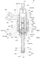
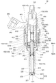
- FIG. 1 is a cross-sectional view showing the internal structure of the fuel injection valve according to the first embodiment.
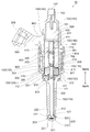
- FIG. 2 is a cross-sectional view showing the internal structure of the fuel injection valve according to the second embodiment.
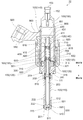
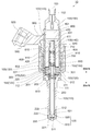
- FIG. 3 is a cross-sectional view showing the internal structure of the fuel injection valve according to the third embodiment.
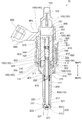
- FIG. 4 is a cross-sectional view showing the internal structure of the fuel injection valve according to the fourth embodiment.
- FIG. 5 is a cross-sectional view showing the internal structure of the fuel injection valve according to the fifth embodiment.
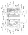
- FIG. 6 is an enlarged view of the configuration of the movable core and the vicinity thereof in FIG.
- FIG. 7 is a cross-sectional view showing the internal structure of the fuel injection valve according to the sixth embodiment.
- the configuration of the fuel injection valve 10 according to the first embodiment will be described with reference to FIG.
- the fuel injection valve 10 is a device for injecting and supplying fuel to an internal combustion engine (not shown).
- the fuel injection valve 10 includes a housing 100, a needle 200, a movable core 300, a fixed core 400, and a coil 600.
- the housing 100 is a member formed as a generally cylindrical container. In FIG. 1, the housing 100 is depicted with its longitudinal direction along the vertical direction. In the following description, words such as “upper side” may be simply used to indicate the upper side in FIG. Further, in order to indicate the lower side in FIG. 1, a word such as “lower side” may be simply used. The same applies to FIGS. 2 to 7 used for later explanation.
- the fuel injected from the fuel injection valve 10 flows from the upper side to the lower side in the housing 100.
- a needle 200, a movable core 300, and a fixed core 400, which will be described later, are accommodated in any housing 100.
- the housing 100 includes a first tubular member 110, a second tubular member 120, a third tubular member 130, a fourth tubular member 140, and a fifth tubular member 150. These are all formed as substantially cylindrical members, and are arranged in a state in which the respective central axes coincide with each other.
- the first cylindrical member 110 is a member disposed in the housing 100 at a position on the most downstream side in the fuel flow direction.
- the first tubular member 110 is made of martensitic stainless steel and is subjected to a quenching process in order to increase its hardness.
- a space 111 is formed inside the first tubular member 110, and a later-described needle 200 is accommodated in the space 111.
- the injection nozzle 500 is press-fitted inward and welded.
- the injection nozzle 500 forms a part of the housing 100 and has a cylindrical portion 520 and a closing portion 510.
- the cylindrical portion 520 is a portion formed in a cylindrical shape.
- the cylindrical portion 520 is fitted inside the first cylindrical member 110 in a state where the central axis thereof coincides with the central axis of the first cylindrical member 110.
- An inner peripheral surface 521 of the cylindrical portion 520 is a surface that slides in a state in which a sliding contact portion 222 (described later) of the needle 200 is in contact.
- the closing portion 510 is a portion formed so as to close the lower end portion of the cylindrical portion 520.
- a nozzle hole 511 is formed in the closing portion 510.
- the nozzle hole 511 is a through hole formed so as to penetrate the center of the closing portion 510 in the vertical direction of FIG. Through the nozzle hole 511, the space 111 inside the first tubular member 110 and the external space communicate with each other.
- the nozzle hole 511 is formed as an outlet for fuel injected from the fuel injection valve 10. As described above, in the fuel injection valve 10, the injection hole 511 for injecting fuel is formed at one end in the longitudinal direction of the housing 100.
- a valve seat 512 is formed on the inner surface of the closing portion 510 so as to surround the periphery of the injection hole 511.
- the valve seat 512 is a portion with which a seal portion 221 (described later) of the needle 200 abuts in order to close the nozzle hole 511.
- the injection nozzle 500 is entirely formed of martensitic stainless steel, and is subjected to a quenching process in order to increase its hardness. Further, the portion of the injection nozzle 500 with which the needle 200 abuts, that is, the valve seat 512 and the inner peripheral surface 521 are subjected to nitriding treatment. The inner peripheral surface 521 is further provided with a DLC coat for reducing the frictional force.
- the portion of the first cylindrical member 110 on the side opposite to the injection nozzle 500 (that is, the upper side) is enlarged in diameter, and the enlarged cylindrical portion 112 is formed so as to extend further upward from the portion. Yes.
- the inner surface of the enlarged diameter cylindrical portion 112 is a portion that slides in a state where a part of the movable core 300 is in contact. For this reason, the enlarged diameter cylindrical portion 112 is subjected to nitriding treatment.
- the lower end of the second cylindrical member 120 is connected to the upper end of the enlarged diameter cylindrical portion 112 (that is, the upper end of the first cylindrical member 110).
- the second tubular member 120 is a cylindrical member disposed in the housing 100 at a position on the upstream side of the first tubular member 110 along the fuel flow direction.
- the inner diameter and the outer diameter of the second cylindrical member 120 are equal to the inner diameter and the outer diameter of the expanded cylindrical portion 112, respectively.
- the 2nd cylindrical member 120 is formed with the ferrite type stainless steel which is a magnetic body.
- the lower end of the third cylindrical member 130 is connected to the upper end of the second cylindrical member 120.
- the third cylindrical member 130 is a cylindrical member arranged in a position on the upstream side of the second cylindrical member 120 along the fuel flow direction in the housing 100.
- the inner diameter and the outer diameter of the third cylindrical member 130 are equal to the inner diameter and the outer diameter of the second cylindrical member 120, respectively.
- the third cylindrical member 130 is made of austenitic stainless steel that is a nonmagnetic material.
- the lower end of the fourth cylindrical member 140 is connected to the upper end of the third cylindrical member 130.
- the fourth tubular member 140 is a cylindrical member disposed in the housing 100 at a position on the upstream side of the third tubular member 130 along the fuel flow direction.
- the inner diameter and outer diameter of the fourth cylindrical member 140 are equal to the inner diameter and outer diameter of the third cylindrical member 130, respectively.
- the fourth cylindrical member 140 is made of a ferritic stainless steel that is a magnetic material.
- the lower end portion of the fifth cylindrical member 150 is press-fitted inward and welded.
- the fifth cylindrical member 150 is a substantially cylindrical member disposed at a position on the most upstream side in the fuel flow direction in the housing 100.
- the fifth cylindrical member 150 is made of austenitic stainless steel.
- An inlet 153 is formed at the upper end of the fifth cylindrical member 150.
- the inlet 153 is an opening formed as an inlet for fuel introduced from the outside.
- a filter 152 is provided at a position in the vicinity of the inlet 153 in the space 151 formed inside the fifth cylindrical member 150.
- the filter 152 is for collecting foreign substances contained in the fuel introduced from the introduction port 153.
- the needle 200 is a rod-shaped member disposed inside the housing 100.
- the needle 200 is arranged so as to be movable along the longitudinal direction (vertical direction in FIG. 1) of the housing 100 with its central axis moved to the central axis of the housing 100.
- the needle 200 is made of martensitic stainless steel and is subjected to a quenching process to increase the hardness.
- a seal portion 221 is formed at the end of the needle 200 on the injection nozzle 500 side.
- the needle 200 moves to the lowermost side in the movable range, the seal portion 221 contacts the valve seat 512 and the injection hole 511 is closed as shown in FIG. Thereby, the fuel injection from the nozzle hole 511 is stopped.
- the needle 200 moves upward and the seal portion 221 moves away from the valve seat 512, the nozzle hole 511 is opened. As a result, fuel is injected from the injection hole 511.
- the needle 200 is provided as a member for switching the opening / closing of the nozzle hole 511 by moving along the longitudinal direction inside the housing 100.
- the side in the direction in which the needle 200 moves so that the nozzle hole 511 is opened that is, the upper side in FIG.
- the side in which the needle 200 moves so that the nozzle hole 511 is closed that is, the lower side in FIG. 1
- valve closing side the side in which the needle 200 moves so that the nozzle hole 511 is closed
- a plurality of sliding contact portions 222 projecting outward are formed at positions slightly closer to the valve opening side than the seal portion 221.
- the sliding contact portion 222 is a portion that slides in a state in which the tip thereof is in contact with the inner peripheral surface 521 of the cylindrical portion 520.
- the plurality of sliding contact portions 222 are formed so as to be aligned along the circumferential direction of the needle 200.
- a recess 223 is formed between the sliding contact portions 222 adjacent to each other as a path for fuel to pass.
- the seal portion 221 and the sliding contact portion 222 are subjected to nitriding treatment.
- the sliding contact portion 222 is further provided with a DLC coat. Thereby, the frictional resistance between the sliding contact part 222 and the inner peripheral surface 521 is reduced.
- the needle 200 is disposed in a state of penetrating a movable core 300, which will be described later, in the vertical direction.
- the upper end portion of the needle 200 is disposed further above the upper end of the movable core 300.
- a large-diameter portion 210 is formed on the side surface of the upper end portion of the needle 200 so as to protrude outward.
- the surface on the movable core 300 side (valve closing side) of the large diameter portion 210 is in contact with the end surface of the movable core 300.
- a space 201 is formed inside the needle 200.
- the space 201 is formed so as to extend from the valve opening side end of the large diameter portion 210 of the needle 200 to a position closer to the valve closing side than the movable core 300.
- a space 201 is open to the outside at the end of the needle 200 on the valve opening side.
- a through hole 202 is formed in the needle 200 at a position closer to the valve closing side than the movable core 300 in the space 201. The space 201 and the space 111 are communicated with each other through the through hole 202.
- the movable core 300 is a member that is formed in a substantially cylindrical shape as a whole.
- the movable core 300 is arranged so as to be movable along the longitudinal direction (vertical direction in FIG. 1) of the housing 100 together with the needle 200 with the central axis thereof being moved to the central axis of the housing 100.
- the movable core 300 has a movable high hardness part 310 and a movable low hardness part 320.
- the movable-side high hardness portion 310 is a substantially cylindrical portion disposed at a position where a part thereof (a portion excluding a diameter-expanded portion 311 described later) is located inside the movable-side low hardness portion 320.
- the movable high hardness part 310 is made of martensitic stainless steel, which is a non-magnetic material and has a relatively high hardness.
- the movable high hardness part 310 is subjected to a quenching process in order to increase its hardness.
- a movable side through hole 313 is formed at the center of the movable side high hardness portion 310 so as to penetrate the movable side high hardness portion 310 in the vertical direction (that is, the longitudinal direction of the housing 100).
- the needle 200 described above is inserted into the movable side through hole 313.
- the outer surface of the needle 200 is slidable in contact with the inner surface of the movable through hole 313.
- the inner surface of the movable side through hole 313 is nitrided.
- the outer surface of the needle 200 is nitrided and further DLC coated.
- the large-diameter portion 210 of the needle 200 is in contact with the end surface on the valve opening side of the movable high hardness portion 310 from above.
- a part of the end face on the valve opening side of the movable high hardness part 310 is a part that contacts the fixed core 400 when the valve is opened, as will be described later.
- nitriding is performed on each of the portion where the large diameter portion 210 of the needle 200 abuts and the portion that contacts the fixed core 400. Further, the end face on the valve closing side of the large diameter portion 210 is also subjected to nitriding treatment.
- the portion on the valve closing side of the movable side high hardness portion 310 is enlarged in diameter, and an enlarged diameter portion 311 protruding toward the side is formed.
- the distal end surface 312 of the enlarged diameter portion 311 is in contact with the inner surface of the enlarged diameter cylindrical portion 112 of the first cylindrical member 110.
- the distal end surface 312 of the enlarged diameter portion 311 slides in a state where it is in contact with the inner surface of the enlarged diameter cylindrical portion 112.
- the tip surface 312 is nitrided and further DLC coated.
- the movable-side low hardness portion 320 is a substantially cylindrical portion disposed at a position outside the movable-side high hardness portion 310.
- the movable-side low hardness portion 320 is fixed to the movable-side high hardness portion 310 by so-called “driving” in a state where the inner surface thereof is in contact with the outer surface of the movable-side high hardness portion 310.
- the end surface on the valve closing side of the movable-side low hardness portion 320 is in contact with the enlarged diameter portion 311 of the movable-side high hardness portion 310.
- the movable-side low-hardness portion 320 is made of a ferritic stainless steel that is a magnetic material. As a result, the movable-side low hardness portion 320 is a portion having a lower hardness than the movable-side high hardness portion 310.
- the position where the movable-side low-hardness portion 320 is disposed inside the housing 100 is a position that generally faces the second tubular member 120.
- the position of the end face on the valve opening side of the movable side low hardness part 320 is slightly closer to the valve closing side than the position of the end face on the valve opening side of the movable side high hardness part 310.
- the upper end surface of the movable high hardness portion 310 protrudes slightly upward (on the fixed core 400 side) from the upper end surface of the movable low hardness portion 320.
- the movable-side high hardness portion 310 extends from one end portion (that is, the upper end portion) along the longitudinal direction of the housing 100 to the other end portion (that is, the lower end portion). Is formed.
- a plurality of through holes 301 penetrating the movable core 300 along the vertical direction are formed at positions near the outer periphery of the movable core 300.
- Each through hole 301 is formed so as to penetrate both the enlarged diameter portion 311 of the movable-side high hardness portion 310 and the movable-side low hardness portion 320. The function of the through hole 301 will be described later.
- the movable-side low hardness portion 320 that is a part of the movable core 300 is formed of a magnetic material
- the movable-side high hardness portion 310 that is the other portion is formed of a nonmagnetic material. Is formed. It may replace with such an aspect and the aspect that the whole movable core 300 is formed with the magnetic body may be sufficient.
- the movable-side high hardness portion 310 is formed of a material having a higher hardness than the movable-side low hardness portion 320.
- the fixed core 400 is a member formed in a substantially cylindrical shape as a whole, like the movable core 300.
- the fixed core 400 is fixed inside the housing 100 with its central axis moved to the central axis of the housing 100.
- the position where the fixed core 400 is provided is a position adjacent to the movable core 300 on the valve opening side. As shown in FIG. 1, when the seal portion 221 of the needle 200 is in contact with the valve seat 512, a gap is formed between the fixed core 400 and the movable core 300.
- the fixed core 400 has a fixed-side high hardness portion 410 and a fixed-side low hardness portion 420.
- the fixed-side high hardness portion 410 is a substantially cylindrical portion disposed at a position inside the fixed-side low hardness portion 420.
- the fixed-side high hardness portion 410 is made of martensitic stainless steel that is a non-magnetic material and has a relatively high hardness.
- the fixed-side high hardness portion 410 is subjected to quenching treatment to increase its hardness.
- the end surface on the movable core 300 side of the fixed-side high hardness portion 410 is a portion where the movable-side high hardness portion 310 of the movable core 300 hits. For this reason, the end face is subjected to nitriding treatment.
- a fixed-side through hole 401 is formed at the center of the fixed-side high hardness portion 410 so as to penetrate the fixed-side high hardness portion 410 in the vertical direction (that is, the longitudinal direction of the housing 100).
- the space 201 of the needle 200 described above is communicated with the space 151 of the fifth cylindrical member 150 through the fixed side through hole 401.
- An enlarged diameter portion 411 is formed on the side surface of the upper end portion of the fixed-side high hardness portion 410 so as to protrude outward.
- the large diameter portion 210 of the needle 200 is inserted from below into the portion on the movable core 300 side of the fixed side through hole 401.
- the inner diameter of the fixed side through hole 401 in the portion is larger than the inner diameter of the fixed side through hole 401 in the other portion. For this reason, a gap is formed between the large diameter portion 210 of the needle 200 and the inner surface of the fixed side through hole 401.
- the fixed-side low hardness portion 420 is a substantially cylindrical portion that is disposed at a position that is entirely outside the fixed-side high hardness portion 410.
- the fixed-side low hardness portion 420 is fixed to the fixed-side high hardness portion 410 by welding in a state where the inner surface thereof is in contact with the outer surface of the fixed-side high hardness portion 410.
- the fixed-side high hardness portion 410 and the fixed-side low hardness portion 420 are welded to each other at a position that becomes the valve opening side end portion of the fixed core 400.
- the fixed-side low-hardness portion 420 is made of a ferrite stainless steel that is a magnetic material. As a result, the fixed-side low hardness portion 420 is a portion having a lower hardness than the fixed-side high hardness portion 410.
- the position where the fixed-side low hardness portion 420 is disposed inside the housing 100 is a position that generally faces the fourth cylindrical member 140.
- the outer surface of the fixed-side low hardness portion 420 is fixed to the inner surface of the fourth tubular member 140 by welding.
- the position of the end face on the valve opening side of the fixed low hardness part 420 is the same as the position of the end face on the valve opening side of the fixed high hardness part 410. Further, the position of the end face on the valve closing side of the fixed low hardness portion 420 is slightly on the valve opening side than the position of the end face on the valve closing side of the fixed high hardness portion 410. In other words, the lower end surface of the fixed-side high hardness portion 410 protrudes slightly downward (movable core 300 side) from the lower end surface of the fixed-side low hardness portion 420.
- the fixed-side high hardness portion 410 extends from one end (that is, the upper end) along the longitudinal direction of the housing 100 to the other end (that is, the lower end). Is formed.
- the lower end surface of the fixed-side high hardness portion 410 is entirely opposed to the upper end surface of the movable-side high hardness portion 310.
- the fixed-side low hardness portion 420 that is a part of the fixed core 400 is formed of a magnetic material
- the fixed-side high hardness portion 410 that is the other portion is formed of a nonmagnetic material. Is formed. It may replace with such an aspect and the aspect that the whole fixed core 400 is formed with the magnetic body may be sufficient.
- the fixed-side high hardness portion 410 is formed of a material having a higher hardness than the fixed-side low hardness portion 420.
- the coil 600 generates a magnetic force upon receiving a current.
- the coil 600 is wound around the bobbin 610 and is disposed so as to cover the entire third cylindrical member 130 and a part of the fourth cylindrical member 140 in the housing 100 from the outside.
- a current is supplied to the coil 600, a magnetic circuit is formed so that the magnetic flux passes through the fixed low hardness portion 420, the movable low hardness portion 320, the second cylindrical member 120, the fourth cylindrical member 140, and the like.
- a magnetic attractive force is generated between the fixed core 400 and the movable core 300. Due to this magnetic attractive force, the movable core 300 moves to the valve opening side together with the needle 200.
- the magnetic attraction force becomes zero. At that time, the movable core 300 moves to the valve closing side together with the needle 200 by a biasing force of a spring 820 described later.
- An adjusting pipe 430 is press-fitted and fixed to an upper portion of the fixed side through hole 401 formed in the fixed side high hardness portion 410.
- the adjusting pipe 430 is a cylindrical member, and a through hole 431 passing through the adjusting pipe 430 in the vertical direction is formed inside thereof.
- a spring 820 is disposed below the adjusting pipe 430 in the fixed side through hole 401.
- the spring 820 is an elastic member whose expansion / contraction direction is along the vertical direction.
- One end of the spring 820 is in contact with the valve closing side end of the adjusting pipe 430.
- the other end of the spring 820 is in contact with the valve opening side end of the large diameter portion 210 of the needle 200.
- the spring 820 is in a state where its length is shorter than the free length. For this reason, the large-diameter portion 210 of the needle 200 is pressed against the movable high hardness portion 310 by the force from the spring 820. As a result, the spring 820 biases both the needle 200 and the movable core 300 toward the valve closing side.
- a spring 810 is disposed below the movable core 300.
- the spring 810 is an elastic member whose expansion / contraction direction is along the vertical direction.
- One end of the spring 810 is in contact with a step portion formed on the valve-closing end surface of the movable high hardness portion 310.
- the other end of the spring 810 is in contact with a step portion formed in the vicinity of the end portion on the valve opening side of the first tubular member 110.
- the spring 810 is in a state where its length is shorter than the free length. For this reason, the movable high hardness portion 310 of the movable core 300 is pressed against the large diameter portion 210 of the needle 200 by the force from the spring 810. As a result, the spring 810 biases both the needle 200 and the movable core 300 toward the valve opening side.
- the state in which the large diameter portion 210 and the movable high hardness portion 310 are in contact with each other is maintained.
- the urging force of the spring 820 is larger than the urging force of the spring 810.
- Part of the coil 600, the fourth cylindrical member 140, and the fifth cylindrical member 150 is molded from the outside with a resin 900.
- a part of the resin 900 protrudes outward, and this protruding portion is formed as a connector 910.
- the connector 910 is a part to which a wire for supplying current to the coil 600 is connected.
- a power supply terminal 920 is disposed inside the connector 910.
- the power supply terminal 920 is a terminal provided at one end of a power supply line connected to the coil 600. The current is supplied to the coil 600 from the power supply terminal 920.
- a holder 700 is disposed on the outer side of the resin 900 where the fourth tubular member 140 is molded.
- the holder 700 is a cylindrical member made of a magnetic material, and is formed so as to extend from a position on the outer side of the enlarged diameter cylindrical portion 112 to a position that is further on the valve opening side than the valve opening side end of the coil 600.
- a cover 710 is disposed inside the holder 700 and at a position closer to the valve opening side than the coil 600.
- the cover 710 is a substantially circular tubular member made of a magnetic material, and is disposed so as to surround the fourth tubular member 140 from the outside. A portion of the cover 710 that is near the connector 910 is cut away to avoid interference with the connector 910. For this reason, in FIG. 1, the cross section of the cover 710 appears only at the position on the right side of the fourth tubular member 140.
- Holder 700 and cover 710 form part of a magnetic circuit through which the magnetic flux generated by coil 600 passes.
- Fuel is supplied to the fifth cylindrical member 150 from the inlet 153.
- the nozzle hole 511 is closed as described above. For this reason, the inside of the fuel injection valve 10 is in a state pressurized by the fuel.
- the fuel After the fuel flows into the space 151 from the introduction port 153, the fuel passes through the through hole 431, the fixed side through hole 401, the space 201, the through hole 202, and the space 111 in order, and is injected from the injection hole 511.
- the periphery of the movable core 300 is filled with the fuel discharged from the through hole 202.
- the fuel present in the valve opening side of the movable core 300 passes through the through-hole 301 that penetrates the movable core 300 and is closed from the movable core 300.
- the movable core 300 that has started to move toward the valve opening side then hits the fixed core 400 and stops.
- the upper end surface of the movable side high hardness portion 310 protrudes toward the fixed core 400 side
- the lower end surface of the fixed side high hardness portion 410 protrudes toward the movable core 300 side. Yes.
- the movable core 300 hits the fixed core 400, while the movable side low hardness portion 320 does not hit the fixed core 400.
- the movable core 300 hits the fixed-side high hardness portion 410 of the fixed core 400, but the movable core 300 does not hit the fixed-side low hardness portion 420.
- the movable core 300 moves to the fixed core 400 side (the valve opening side) together with the needle 200 by the generated magnetic attractive force.
- the movable high hardness portion 310 is configured to contact the fixed high hardness portion 410.
- a relatively hard portion (movable high hardness portion 310) of the movable core 300 and a relatively hard portion (fixed side high hardness portion 410) of the fixed core 400 collide with each other. . For this reason, in any of the fixed core and the movable core, occurrence of damage due to the collision is suppressed.
- the movable-side low hardness part 320 and the fixed-side low hardness part 420 which are parts that contribute to the magnetic attractive force, are formed of a magnetic material having relatively low hardness, but other members collide with them. It has a configuration that does not.
- the magnetic body is prevented from being damaged by a collision while being configured to be able to efficiently generate a magnetic attractive force using the magnetic body.
- the movable-side high-hardness portion 310 is formed so as to extend from one end (that is, the upper end) along the longitudinal direction of the housing 100 to the other end (that is, the lower end) of the movable core 300. Yes. For this reason, when the movable core 300 hits the fixed core 400, for example, compared to a configuration in which the end on the valve closing side of the movable high hardness portion 310 is supported by the movable low hardness portion 320, The impact applied to the movable side low hardness part 320 is reduced. For this reason, damage to the movable side low hardness part 320 with low hardness is further prevented.
- the fixed-side high hardness portion 410 extends from the one end portion (that is, the upper end portion) of the fixed core 400 along the longitudinal direction of the housing 100 to the other end portion (that is, the lower end portion). Is formed. For this reason, when the movable core 300 hits the fixed core 400, for example, compared to a configuration in which the end portion on the valve opening side of the fixed-side high hardness portion 410 is supported by the fixed-side low hardness portion 420, The impact applied to the fixed-side low hardness portion 420 is reduced. For this reason, damage to the fixed-side low hardness portion 420 having low hardness is further prevented.
- the fixed-side high hardness portion 410 is disposed at a position inside the fixed-side low hardness portion 420, and the movable-side high hardness portion 310 is positioned inside the movable-side low hardness portion 320.
- the movable core 300 is formed with a movable side through hole 313 that penetrates the center of the movable side high hardness portion 310 along the longitudinal direction, and the needle 200 is inserted into the movable side through hole 313. ing.
- the needle 200 contacts and slides only on a portion of the movable core 300 having a high hardness, wear of the movable core 300 is suppressed.
- the operating characteristics of the fuel injection valve 10 are further prevented from changing in a short period due to the deformation of the movable core 300.
- the enlarged diameter portion 311 of the movable high-hardness portion 310 is configured to slide while being in contact with the inner surface of the housing 100 (specifically, the inner surface of the enlarged diameter cylindrical portion 112). .
- the wear of the movable core 300 is suppressed compared to a configuration in which the movable-side low-hardness portion 320 having a low hardness contacts and slides on the inner surface of the housing 100. This further prevents the operating characteristics of the fuel injection valve 10 from changing in a short period due to the deformation of the movable core 300.
- a pair of members that slide in contact with each other as the movable core 300 and the needle 200 move (hereinafter, one is referred to as a “first member” and the other is a “second member”.
- a surface treatment (specifically, DLC coating) for reducing the frictional force, and at least one of the surface treatment (specifically quenching and nitriding treatment) for increasing the hardness. Is given. Thereby, the breakage
- Examples of the combination of the first member and the second member include the needle 200 and the injection nozzle 500, the needle 200 and the movable-side high hardness portion 310, and the first cylindrical member 110 and the movable-side high hardness portion 310.
- the above-described hardness increasing treatment and surface treatment are applied to at least one of all the portions that slide in contact with each other.
- the high hardness treatment may be performed on only one of the first member and the second member, or may be performed on both.
- the first member and the second member that are not subjected to the high hardness treatment may be present in a part of the fuel injection valve 10.
- the surface treatment for reducing the frictional force may be applied to only one of the first member and the second member, or may be applied to both. Further, the first member and the second member that are not subjected to the surface treatment for reducing the frictional force may be present in a part of the fuel injection valve 10.
- quenching and nitriding treatment may be used as in this embodiment, but treatments other than quenching and nitriding treatment may be used.
- a DLC coat may be used as in the present embodiment, but a treatment other than the DLC coat may be used.
- the second embodiment will be described with reference to FIG.
- differences from the first embodiment will be mainly described, and description of points that are common to the first embodiment will be omitted as appropriate.
- the tip of the enlarged diameter portion 411 formed at the valve opening side portion of the fixed high hardness portion 410 is in contact with the inner surface of the fourth cylindrical member 140, It is fixed by welding.
- the outer surface of the fixed-side low hardness portion 420 and the inner surface of the fourth cylindrical member 140 are slightly separated from each other, and both are not welded.
- the enlarged diameter portion 411 of the fixed-side high hardness portion 410 is joined to the inner surface of the housing.
- the impact when the movable core 300 hits the fixed core 400 when the valve is opened is directly applied only to the fixed-side high hardness portion 410, and the fixed-side low hardness portion 420 has Cannot be added. For this reason, it is possible to further prevent the fixed-side low hardness portion 420 having a low hardness from being damaged.
- the third embodiment will be described with reference to FIG.
- differences from the first embodiment will be mainly described, and description of points that are common to the first embodiment will be omitted as appropriate.
- the movable side high hardness portion 310 is not provided with the enlarged diameter portion 311.
- the movable high hardness part 310 is entirely formed in a cylindrical shape, and the end on the valve closing side extends further to the valve closing side than the valve closing side end of the movable low hardness part 320. .
- a portion of the movable high hardness portion 310 that extends further to the valve closing side than the valve closing end of the movable low hardness portion 320 is also referred to as an “extension portion 315” below.
- the extension part 315 extends to the inside of the space 111 of the first tubular member 110.
- the position of the end portion on the valve closing side of the extension portion 315 is a position slightly on the valve opening side with respect to the through hole 202.
- the valve closing side end of the extension 315 is in contact with the end of the spring 810.
- the outer side surface 316 of the extension part 315 is slidable in a state of being in contact with the inner surface of the first tubular member 110 that defines the space 111.
- the outer side surface 316 is subjected to nitriding and DLC coating in the same manner as the front end surface 312 in the first embodiment. Further, the inner surface of the first cylindrical member 110 facing this is subjected to nitriding treatment.
- the length of the movable core 300 that is guided to slide that is, the length of the extension 315 in the vertical direction is larger than the length of the tip surface 312 (first embodiment) in the vertical direction. It is getting longer. For this reason, it is possible to further stabilize the movement of the movable core 300 at the time of valve opening and valve closing.
- the first cylindrical member 110 of the present embodiment is not formed with the enlarged cylindrical portion 112 that surrounds the movable core 300 from the outer periphery. Instead, the second cylindrical member 120 is extended to the lower side. This is because there is no need to provide a portion (that is, the enlarged diameter cylindrical portion 112) in which the enlarged diameter portion 311 of the movable high hardness portion 310 contacts and slides in the vicinity of the second cylindrical member 120 in this embodiment. is there. In such a configuration, when the second cylindrical member 120 is extended, the magnetic resistance in the portion is reduced. As a result, the magnetic attractive force generated between the fixed core 400 and the movable core 300 is increased, and the fuel injection valve is opened more efficiently.
- the fourth embodiment will be described with reference to FIG.
- differences from the first embodiment will be mainly described, and description of points that are common to the first embodiment will be omitted as appropriate.
- the fuel injection valve 10 has a configuration in which an extension 315 similar to that of the third embodiment (FIG. 3) is formed on the movable high hardness portion 310 similar to that of the first embodiment. That is, the movable high-hardness portion 310 according to the present embodiment slides in contact with the first tubular member 110 at two locations, that is, the tip surface 312 of the enlarged diameter portion 311 and the outer surface 316 of the extension portion 315. .
- a damper chamber 303 that is a space sandwiched between the enlarged diameter portion 311 and the first tubular member 110 is formed at a position closer to the valve closing side than the enlarged diameter portion 311.
- a space 304 is formed between the movable core 300 and the fixed core 400.
- the damper chamber 303 and the space 304 are both filled with fuel.
- the damper chamber 303 and the space 304 are communicated with each other through a through hole that penetrates the movable core 300.
- An orifice 302 is provided in the through hole 301 of the present embodiment, and the flow passage cross-sectional area of the fuel in the through hole 301 is reduced.
- a communication path 421 that is a slit-like groove extending in the vertical direction is formed on the outer peripheral surface of the fixed-side low hardness portion 420.
- the valve-closing space 304 and the valve-opening space 151 communicate with each other through the communication passage 421. For this reason, the fuel pressure in the space 304 is substantially constant regardless of the operating state and position of the movable core 300.
- the fifth embodiment will be described with reference to FIGS.
- differences from the above-described fourth embodiment (FIG. 4) will be mainly described, and description of points common to the fourth embodiment will be omitted as appropriate.
- some through holes 301 are provided with the orifices 302 of the fourth embodiment, while other partial through holes 301 are provided with valves 306.
- the through hole 301 provided with the orifice 302 is hereinafter also referred to as “through hole 301A”. Further, the through hole 301 on which the valve 306 is provided is also referred to as “through hole 301B” below.
- the valve 306 is movable in the vertical direction according to the fuel flow and pressure in the through hole 301B. While the valve 306 prohibits the flow of fuel that goes through the through hole 301B in the valve opening direction, the flow of fuel that passes through the through hole 301B in the valve closing direction is allowed. That is, the valve 306 functions as a so-called “check valve”.
- the movable core 300 and the needle 200 move quickly in the valve opening direction when the valve is opened, while the moving speed of the movable core 300 and the needle 200 is reduced by the orifice 302 when the valve is closed. Is done. In the case where it is more important to keep the collision energy between the seal part 221 and the valve seat 512 lower than to keep the collision energy between the movable side high hardness part 310 and the fixed side high hardness part 410 low, this Such a configuration is preferable.
- the portions around the through holes 301 ⁇ / b> A and 301 ⁇ / b> B protrude toward the valve opening side from the other portions. Yes.
- This protruding portion is also referred to as “bank portion 325” below.
- the size of the gap between the movable core 300 and the fixed core 400 is about 10 ⁇ m at the bank portion 325. It is set to be about 50 ⁇ m around it.
- This protruding portion is also referred to as “bank portion 318” below.
- a space outside the bank portion 318 is also referred to as an “outer damper chamber 303A” below.
- the space inside the bank portion 318 is hereinafter also referred to as “inner damper chamber 303B”.
- the distance between the bank portion 325 and the first tubular member 110 gradually decreases.
- the distance is less than 50 ⁇ m, the flow resistance acting on the fuel flowing through the gap between the two rapidly increases, and the flow of fuel flowing from the outer damper chamber 303A into the inner damper chamber 303B is hindered.
- the valve closing by the needle 200 is completed, when the movable core 300 continues to move downward and collides with the first cylindrical member 110, the moving speed of the movable core 300 is reduced. And the first cylinder member 110 can be kept low in collision energy.
- the sixth embodiment will be described with reference to FIG.
- differences from the first embodiment will be mainly described, and description of points that are common to the first embodiment will be omitted as appropriate.
- the movable side high hardness portion 310 of the movable core 300 and the upper side portion of the needle 200 are integrated.
- the portion of the needle 200 that corresponds to the fixed-side low hardness portion 420 is also subjected to nitriding treatment in this embodiment.
- the nitriding treatment and the DLC coat are also applied to the portion of the needle 200 that contacts and slides on the enlarged cylindrical portion 112 of the first cylindrical member 110 (that is, the distal end surface 312 of the enlarged diameter portion 311). It has been subjected. Even if it is such an aspect, there exists an effect similar to what was demonstrated in 1st Embodiment.
Landscapes
- Engineering & Computer Science (AREA)
- Chemical & Material Sciences (AREA)
- Combustion & Propulsion (AREA)
- Mechanical Engineering (AREA)
- General Engineering & Computer Science (AREA)
- Physics & Mathematics (AREA)
- Electromagnetism (AREA)
- Fuel-Injection Apparatus (AREA)
- Magnetically Actuated Valves (AREA)
Priority Applications (2)
| Application Number | Priority Date | Filing Date | Title |
|---|---|---|---|
| DE112018002252.8T DE112018002252T5 (de) | 2017-04-28 | 2018-03-16 | Kraftstoffeinspritzventil |
| US16/665,579 US20210108603A1 (en) | 2017-04-28 | 2019-10-28 | Fuel injection valve |
Applications Claiming Priority (2)
| Application Number | Priority Date | Filing Date | Title |
|---|---|---|---|
| JP2017090295A JP6836955B2 (ja) | 2017-04-28 | 2017-04-28 | 燃料噴射弁 |
| JP2017-090295 | 2017-04-28 |
Related Child Applications (1)
| Application Number | Title | Priority Date | Filing Date |
|---|---|---|---|
| US16/665,579 Continuation US20210108603A1 (en) | 2017-04-28 | 2019-10-28 | Fuel injection valve |
Publications (1)
| Publication Number | Publication Date |
|---|---|
| WO2018198592A1 true WO2018198592A1 (ja) | 2018-11-01 |
Family
ID=63918913
Family Applications (1)
| Application Number | Title | Priority Date | Filing Date |
|---|---|---|---|
| PCT/JP2018/010587 Ceased WO2018198592A1 (ja) | 2017-04-28 | 2018-03-16 | 燃料噴射弁 |
Country Status (4)
| Country | Link |
|---|---|
| US (1) | US20210108603A1 (enExample) |
| JP (1) | JP6836955B2 (enExample) |
| DE (1) | DE112018002252T5 (enExample) |
| WO (1) | WO2018198592A1 (enExample) |
Cited By (2)
| Publication number | Priority date | Publication date | Assignee | Title |
|---|---|---|---|---|
| EP3636911A1 (en) * | 2018-10-08 | 2020-04-15 | Continental Automotive GmbH | Valve assembly for an injection valve and fuel injection valve |
| CN113167200A (zh) * | 2019-01-28 | 2021-07-23 | 株式会社电装 | 燃料喷射装置 |
Families Citing this family (5)
| Publication number | Priority date | Publication date | Assignee | Title |
|---|---|---|---|---|
| JP7352384B2 (ja) * | 2019-06-06 | 2023-09-28 | 株式会社Soken | 燃料噴射弁 |
| JP7268546B2 (ja) * | 2019-09-03 | 2023-05-08 | 株式会社デンソー | インジェクタ |
| JP7323445B2 (ja) | 2019-12-26 | 2023-08-08 | 株式会社Soken | 燃料噴射弁 |
| JP7323444B2 (ja) | 2019-12-26 | 2023-08-08 | 株式会社Soken | 燃料噴射弁 |
| JP7376366B2 (ja) * | 2020-01-07 | 2023-11-08 | 株式会社Soken | 燃料噴射弁の製造方法 |
Citations (6)
| Publication number | Priority date | Publication date | Assignee | Title |
|---|---|---|---|---|
| JP2000170619A (ja) * | 1998-12-09 | 2000-06-20 | Keihin Corp | 電磁式燃料噴射弁のコアの製造方法 |
| JP2002349745A (ja) * | 2001-05-25 | 2002-12-04 | Nippon Soken Inc | 電磁弁 |
| JP2004088891A (ja) * | 2002-08-26 | 2004-03-18 | Nippon Soken Inc | 電磁アクチュエータ |
| US20120153034A1 (en) * | 2010-12-20 | 2012-06-21 | Caterpillar Inc. | Solenoid Actuator And Fuel Injector Using Same |
| EP2719886A1 (en) * | 2012-10-10 | 2014-04-16 | Continental Automotive GmbH | Valve assembly for an injection valve |
| JP2017031963A (ja) * | 2015-08-06 | 2017-02-09 | 株式会社デンソー | 燃料噴射装置 |
Family Cites Families (2)
| Publication number | Priority date | Publication date | Assignee | Title |
|---|---|---|---|---|
| JP5862941B2 (ja) | 2011-11-08 | 2016-02-16 | 株式会社デンソー | 燃料噴射弁 |
| JP2017090295A (ja) | 2015-11-12 | 2017-05-25 | 株式会社イシダ | 組合せ計量装置 |
-
2017
- 2017-04-28 JP JP2017090295A patent/JP6836955B2/ja active Active
-
2018
- 2018-03-16 DE DE112018002252.8T patent/DE112018002252T5/de active Pending
- 2018-03-16 WO PCT/JP2018/010587 patent/WO2018198592A1/ja not_active Ceased
-
2019
- 2019-10-28 US US16/665,579 patent/US20210108603A1/en not_active Abandoned
Patent Citations (6)
| Publication number | Priority date | Publication date | Assignee | Title |
|---|---|---|---|---|
| JP2000170619A (ja) * | 1998-12-09 | 2000-06-20 | Keihin Corp | 電磁式燃料噴射弁のコアの製造方法 |
| JP2002349745A (ja) * | 2001-05-25 | 2002-12-04 | Nippon Soken Inc | 電磁弁 |
| JP2004088891A (ja) * | 2002-08-26 | 2004-03-18 | Nippon Soken Inc | 電磁アクチュエータ |
| US20120153034A1 (en) * | 2010-12-20 | 2012-06-21 | Caterpillar Inc. | Solenoid Actuator And Fuel Injector Using Same |
| EP2719886A1 (en) * | 2012-10-10 | 2014-04-16 | Continental Automotive GmbH | Valve assembly for an injection valve |
| JP2017031963A (ja) * | 2015-08-06 | 2017-02-09 | 株式会社デンソー | 燃料噴射装置 |
Cited By (3)
| Publication number | Priority date | Publication date | Assignee | Title |
|---|---|---|---|---|
| EP3636911A1 (en) * | 2018-10-08 | 2020-04-15 | Continental Automotive GmbH | Valve assembly for an injection valve and fuel injection valve |
| CN113167200A (zh) * | 2019-01-28 | 2021-07-23 | 株式会社电装 | 燃料喷射装置 |
| CN113167200B (zh) * | 2019-01-28 | 2022-08-02 | 株式会社电装 | 燃料喷射装置 |
Also Published As
| Publication number | Publication date |
|---|---|
| DE112018002252T5 (de) | 2020-01-16 |
| JP2018189002A (ja) | 2018-11-29 |
| US20210108603A1 (en) | 2021-04-15 |
| JP6836955B2 (ja) | 2021-03-03 |
Similar Documents
| Publication | Publication Date | Title |
|---|---|---|
| JP6836955B2 (ja) | 燃料噴射弁 | |
| WO2016163110A1 (ja) | 燃料噴射弁 | |
| US20170254304A1 (en) | Fuel injection valve | |
| WO2017022163A1 (ja) | 燃料噴射装置 | |
| JP6187422B2 (ja) | 燃料噴射弁 | |
| JP7323445B2 (ja) | 燃料噴射弁 | |
| WO2020246385A1 (ja) | 燃料噴射弁 | |
| JP6544416B2 (ja) | 燃料噴射弁 | |
| US10718302B2 (en) | Fuel injection device | |
| JP7311315B2 (ja) | 燃料噴射弁 | |
| CN111344483B (zh) | 燃料喷射装置 | |
| JP6733701B2 (ja) | インジェクタ | |
| JP7116609B2 (ja) | 燃料噴射弁 | |
| JP2019203406A (ja) | 燃料噴射弁 | |
| EP3156638B1 (en) | Fuel injector | |
| JP6160562B2 (ja) | 燃料噴射弁 | |
| JP7063741B2 (ja) | 燃料噴射弁 | |
| JP7284063B2 (ja) | 燃料噴射弁 | |
| JP7323444B2 (ja) | 燃料噴射弁 | |
| JP7376337B2 (ja) | 燃料噴射弁 | |
| KR102196142B1 (ko) | 분사 밸브를 위한 밸브 조립체 및 분사 밸브 | |
| WO2019017097A1 (ja) | 燃料噴射弁 | |
| JP2015218664A (ja) | 燃料噴射弁 | |
| JP4191760B2 (ja) | 燃料噴射弁 | |
| JP6460134B2 (ja) | 燃料噴射弁 |
Legal Events
| Date | Code | Title | Description |
|---|---|---|---|
| 121 | Ep: the epo has been informed by wipo that ep was designated in this application |
Ref document number: 18789879 Country of ref document: EP Kind code of ref document: A1 |
|
| 122 | Ep: pct application non-entry in european phase |
Ref document number: 18789879 Country of ref document: EP Kind code of ref document: A1 |