WO2018198592A1 - Fuel injection valve - Google Patents
Fuel injection valve Download PDFInfo
- Publication number
- WO2018198592A1 WO2018198592A1 PCT/JP2018/010587 JP2018010587W WO2018198592A1 WO 2018198592 A1 WO2018198592 A1 WO 2018198592A1 JP 2018010587 W JP2018010587 W JP 2018010587W WO 2018198592 A1 WO2018198592 A1 WO 2018198592A1
- Authority
- WO
- WIPO (PCT)
- Prior art keywords
- movable
- fixed
- core
- high hardness
- needle
- Prior art date
Links
Images
Classifications
-
- F—MECHANICAL ENGINEERING; LIGHTING; HEATING; WEAPONS; BLASTING
- F02—COMBUSTION ENGINES; HOT-GAS OR COMBUSTION-PRODUCT ENGINE PLANTS
- F02M—SUPPLYING COMBUSTION ENGINES IN GENERAL WITH COMBUSTIBLE MIXTURES OR CONSTITUENTS THEREOF
- F02M51/00—Fuel-injection apparatus characterised by being operated electrically
- F02M51/06—Injectors peculiar thereto with means directly operating the valve needle
- F02M51/061—Injectors peculiar thereto with means directly operating the valve needle using electromagnetic operating means
- F02M51/0625—Injectors peculiar thereto with means directly operating the valve needle using electromagnetic operating means characterised by arrangement of mobile armatures
- F02M51/0664—Injectors peculiar thereto with means directly operating the valve needle using electromagnetic operating means characterised by arrangement of mobile armatures having a cylindrically or partly cylindrically shaped armature, e.g. entering the winding; having a plate-shaped or undulated armature entering the winding
- F02M51/0685—Injectors peculiar thereto with means directly operating the valve needle using electromagnetic operating means characterised by arrangement of mobile armatures having a cylindrically or partly cylindrically shaped armature, e.g. entering the winding; having a plate-shaped or undulated armature entering the winding the armature and the valve being allowed to move relatively to each other or not being attached to each other
-
- F—MECHANICAL ENGINEERING; LIGHTING; HEATING; WEAPONS; BLASTING
- F02—COMBUSTION ENGINES; HOT-GAS OR COMBUSTION-PRODUCT ENGINE PLANTS
- F02M—SUPPLYING COMBUSTION ENGINES IN GENERAL WITH COMBUSTIBLE MIXTURES OR CONSTITUENTS THEREOF
- F02M51/00—Fuel-injection apparatus characterised by being operated electrically
- F02M51/06—Injectors peculiar thereto with means directly operating the valve needle
-
- F—MECHANICAL ENGINEERING; LIGHTING; HEATING; WEAPONS; BLASTING
- F02—COMBUSTION ENGINES; HOT-GAS OR COMBUSTION-PRODUCT ENGINE PLANTS
- F02M—SUPPLYING COMBUSTION ENGINES IN GENERAL WITH COMBUSTIBLE MIXTURES OR CONSTITUENTS THEREOF
- F02M61/00—Fuel-injectors not provided for in groups F02M39/00 - F02M57/00 or F02M67/00
- F02M61/04—Fuel-injectors not provided for in groups F02M39/00 - F02M57/00 or F02M67/00 having valves, e.g. having a plurality of valves in series
- F02M61/10—Other injectors with elongated valve bodies, i.e. of needle-valve type
-
- F—MECHANICAL ENGINEERING; LIGHTING; HEATING; WEAPONS; BLASTING
- F02—COMBUSTION ENGINES; HOT-GAS OR COMBUSTION-PRODUCT ENGINE PLANTS
- F02M—SUPPLYING COMBUSTION ENGINES IN GENERAL WITH COMBUSTIBLE MIXTURES OR CONSTITUENTS THEREOF
- F02M2200/00—Details of fuel-injection apparatus, not otherwise provided for
- F02M2200/26—Fuel-injection apparatus with elastically deformable elements other than coil springs
-
- F—MECHANICAL ENGINEERING; LIGHTING; HEATING; WEAPONS; BLASTING
- F02—COMBUSTION ENGINES; HOT-GAS OR COMBUSTION-PRODUCT ENGINE PLANTS
- F02M—SUPPLYING COMBUSTION ENGINES IN GENERAL WITH COMBUSTIBLE MIXTURES OR CONSTITUENTS THEREOF
- F02M2200/00—Details of fuel-injection apparatus, not otherwise provided for
- F02M2200/28—Details of throttles in fuel-injection apparatus
-
- F—MECHANICAL ENGINEERING; LIGHTING; HEATING; WEAPONS; BLASTING
- F02—COMBUSTION ENGINES; HOT-GAS OR COMBUSTION-PRODUCT ENGINE PLANTS
- F02M—SUPPLYING COMBUSTION ENGINES IN GENERAL WITH COMBUSTIBLE MIXTURES OR CONSTITUENTS THEREOF
- F02M2200/00—Details of fuel-injection apparatus, not otherwise provided for
- F02M2200/30—Fuel-injection apparatus having mechanical parts, the movement of which is damped
- F02M2200/304—Fuel-injection apparatus having mechanical parts, the movement of which is damped using hydraulic means
-
- F—MECHANICAL ENGINEERING; LIGHTING; HEATING; WEAPONS; BLASTING
- F02—COMBUSTION ENGINES; HOT-GAS OR COMBUSTION-PRODUCT ENGINE PLANTS
- F02M—SUPPLYING COMBUSTION ENGINES IN GENERAL WITH COMBUSTIBLE MIXTURES OR CONSTITUENTS THEREOF
- F02M2200/00—Details of fuel-injection apparatus, not otherwise provided for
- F02M2200/90—Selection of particular materials
- F02M2200/9053—Metals
- F02M2200/9069—Non-magnetic metals
Landscapes
- Engineering & Computer Science (AREA)
- Chemical & Material Sciences (AREA)
- Combustion & Propulsion (AREA)
- Mechanical Engineering (AREA)
- General Engineering & Computer Science (AREA)
- Physics & Mathematics (AREA)
- Electromagnetism (AREA)
- Fuel-Injection Apparatus (AREA)
- Magnetically Actuated Valves (AREA)
Abstract
A fuel injection valve (10) is provided with a fixed core (400) and a movable core (300). The fixed core includes a fixed-side high-hardness section (410) having a high hardness, and a fixed-side low-hardness section (420) having a hardness lower than that of the fixed-side high-hardness section. The movable core includes a movable-side high-hardness section (310) having a high hardness, and a movable-side low-hardness section (320) having a hardness lower than that of the movable-side high-hardness section. When a current is supplied to a coil (600), the resulting magnetic attractive force causes the movable core to move together with a needle (200) to the fixed core side, and causes the movable-side high-hardness section to abut against the fixed-side high-hardness section.
Description
本出願は、2017年4月28日に出願された日本国特許出願2017-090295号に基づくものであって、その優先権の利益を主張するものであり、その特許出願の全ての内容が、参照により本明細書に組み込まれる。
This application is based on Japanese Patent Application No. 2017-090295 filed on April 28, 2017, and claims the benefit of its priority. Which is incorporated herein by reference.
本開示は燃料噴射弁に関する。
This disclosure relates to a fuel injection valve.
内燃機関に設けられる燃料噴射弁として、磁気吸引力によって内部の可動コアをニードルと共に動作させることにより、燃料の出口である噴孔の開閉を切り換える構成のものが知られている。
2. Description of the Related Art As a fuel injection valve provided in an internal combustion engine, there is known a configuration in which opening and closing of a nozzle hole, which is a fuel outlet, is switched by operating an internal movable core together with a needle by a magnetic attractive force.
例えば下記特許文献1に記載の燃料噴射弁は、ハウジングの内部に固定された固定コアと、ハウジングの内部において移動可能な状態で配置された可動コアと、固定コアと可動コアとの間に磁気吸引力を発生させるコイルと、を備えている。燃料噴射弁から燃料が噴射される際には、コイルに電流が供給される。そのとき発生した磁気吸引力によって、可動コアがニードルと共に固定コア側に移動し、噴孔が開かれた状態となる。
For example, a fuel injection valve described in Patent Document 1 below includes a fixed core fixed inside a housing, a movable core arranged so as to be movable inside the housing, and a magnet between the fixed core and the movable core. A coil for generating a suction force. When fuel is injected from the fuel injection valve, a current is supplied to the coil. Due to the magnetic attractive force generated at that time, the movable core moves to the fixed core side together with the needle, and the nozzle hole is opened.
ところで、燃料噴射弁においては、固定コアなどの構成部品の形状が摩耗や損傷によって変化してしまうと、燃料の噴射量等の特性が変化してしまう。このため、燃料噴射弁では、構成部品の摩耗や損傷を可能な限り抑制する必要がある。
Incidentally, in the fuel injection valve, when the shape of a component such as a fixed core changes due to wear or damage, characteristics such as the fuel injection amount change. For this reason, in a fuel injection valve, it is necessary to suppress wear and damage of components as much as possible.
上記の燃料噴射弁の固定コアには、比較的硬度の高い材料で形成されたブッシュが設けられている。ニードルは、固定コアに直接は接しておらず、上記のブッシュに当接した状態で移動する。このため、比較的硬度の低い磁性体からなる固定コアが、ニードルとの摺接によって摩耗してしまうことが防止される。
The fixed core of the fuel injection valve is provided with a bush made of a relatively hard material. The needle is not in direct contact with the fixed core, but moves in contact with the bush. For this reason, it is possible to prevent the fixed core made of a magnetic material having a relatively low hardness from being worn by sliding contact with the needle.
また、燃料噴射弁から燃料が噴射される際には、上記のように可動コアが固定コア側に移動するのであるが、最終的には可動コアは固定コアに当たるのではなく、固定コアに設けられた上記のブッシュに当たって止まることとなる。上記の燃料噴射弁では、固定コアに対し可動コアが直接衝突しないので、固定コアの摩耗や損傷を更に抑制することが可能となっている。
In addition, when fuel is injected from the fuel injection valve, the movable core moves to the fixed core side as described above. However, the movable core does not hit the fixed core, but is provided on the fixed core. It will stop when it hits the above-mentioned bush. In the fuel injection valve, since the movable core does not directly collide with the fixed core, it is possible to further suppress wear and damage of the fixed core.
上記特許文献1に記載の燃料噴射弁では、比較的硬度の高い材料からなるブッシュに対し、比較的硬度の低い材料からなる可動コアが衝突することとなる。このため、衝突による可動コアの損傷が懸念される。特に、噴射される燃料として気体燃料が用いられる場合には、燃料の粘度が低いために可動コアの移動速度が大きくなるので、上記のような可動コアの損傷が生じる可能性が高くなってしまう。燃料噴射弁の動作特性を長期間に亘り一定に維持するためには、固定コアのみならず可動コアの損傷をも防止することが好ましい。
In the fuel injection valve described in Patent Document 1, a movable core made of a material having a relatively low hardness collides with a bush made of a material having a relatively high hardness. For this reason, there is a concern about the damage of the movable core due to the collision. In particular, when gaseous fuel is used as the fuel to be injected, the moving speed of the movable core increases because the viscosity of the fuel is low, so that there is a high possibility that the movable core will be damaged as described above. . In order to maintain the operating characteristics of the fuel injection valve constant over a long period of time, it is preferable to prevent not only the fixed core but also the movable core from being damaged.
本開示は、固定コア及び可動コアの損傷を防止することのできる燃料噴射弁、を提供することを目的とする。
This disclosure is intended to provide a fuel injection valve that can prevent damage to a fixed core and a movable core.
本開示に係る燃料噴射弁は、燃料を噴射するための噴孔が、長手方向における一端に形成されたハウジングと、ハウジングの内部において長手方向に沿って移動することにより、噴孔の開閉を切り換えるニードルと、少なくとも一部が磁性体によって形成された部材であって、ハウジングの内部に固定されている固定コアと、少なくとも一部が磁性体によって形成された部材であって、ハウジングの内部において、長手方向に沿ってニードルと共に移動可能な状態で配置されている可動コアと、固定コアと可動コアとの間に磁気吸引力を発生させるコイルと、を備える。固定コアは、硬度が高い固定側高硬度部と、固定側高硬度部よりも硬度が低い固定側低硬度部と、を有している。可動コアは、硬度が高い可動側高硬度部と、可動側高硬度部よりも硬度が低い可動側低硬度部と、を有している。この燃料噴射弁は、コイルに電流が供給されると、発生した磁気吸引力によって可動コアがニードルと共に固定コア側に移動し、可動側高硬度部が固定側高硬度部に当たるように構成されている。
In the fuel injection valve according to the present disclosure, an injection hole for injecting fuel switches between opening and closing of the injection hole by moving along the longitudinal direction inside the housing with a housing formed at one end in the longitudinal direction. A needle, a member formed at least partly by a magnetic body, a fixed core fixed inside the housing, and a member formed at least partly by a magnetic body, and inside the housing, A movable core disposed in a movable state along with the needle along the longitudinal direction; and a coil that generates a magnetic attractive force between the fixed core and the movable core. The fixed core has a fixed-side high hardness portion having a high hardness and a fixed-side low hardness portion having a hardness lower than that of the fixed side high hardness portion. The movable core includes a movable side high hardness portion having a high hardness and a movable side low hardness portion having a hardness lower than that of the movable side high hardness portion. This fuel injection valve is configured such that when a current is supplied to a coil, the movable core moves to the fixed core side together with the needle by the generated magnetic attraction force, and the movable high hardness portion hits the fixed high hardness portion. Yes.
このような構成の燃料噴射弁では、固定コアはその全体が硬度の低い磁性体材料によって形成されているのではなく、一部が硬度の高い固定側高硬度部となっている。同様に、可動コアはその全体が硬度の低い磁性体材料によって形成されているのではなく、一部が硬度の高い可動側高硬度部となっている。
In the fuel injection valve having such a configuration, the fixed core is not entirely formed of a magnetic material having low hardness, but a part thereof is a fixed-side high hardness portion having high hardness. Similarly, the movable core is not entirely formed of a magnetic material having a low hardness, but a part of the movable core is a movable-side high hardness portion having a high hardness.
燃料を噴射させるためにコイルに電流が供給され、可動コアがニードルと共に固定コア側に移動すると、可動側高硬度部が固定側高硬度部に当たることとなる。比較的硬度の高い部分同士が衝突するので、固定コア及び可動コアのいずれにおいても、衝突による損傷の発生が抑制される。
When an electric current is supplied to the coil in order to inject fuel and the movable core moves to the fixed core side together with the needle, the movable side high hardness portion hits the fixed side high hardness portion. Since the relatively hard parts collide with each other, the occurrence of damage due to the collision is suppressed in both the fixed core and the movable core.
例えば、固定コアのうち固定側低硬度部を磁性体によって形成しておけば、固定側高硬度部は、磁気吸引力の発生に寄与する必要はない。このため、比較的硬度の高い非磁性体で固定側高硬度部を形成することができる。同様に、可動コアのうち可動側低硬度部を磁性体によって形成しておけば、可動側高硬度部は、磁気吸引力の発生に寄与する必要はない。このため、比較的硬度の高い非磁性体で可動側高硬度部を形成することができる。
For example, if the fixed-side low hardness portion of the fixed core is formed of a magnetic material, the fixed-side high hardness portion does not need to contribute to the generation of the magnetic attractive force. For this reason, the fixed-side high hardness portion can be formed of a nonmagnetic material having a relatively high hardness. Similarly, if the movable-side low hardness portion of the movable core is formed of a magnetic material, the movable-side high hardness portion does not need to contribute to the generation of the magnetic attractive force. For this reason, the movable-side high hardness portion can be formed of a nonmagnetic material having a relatively high hardness.
本開示によれば、固定コア及び可動コアの損傷を防止することのできる燃料噴射弁、が提供される。
According to the present disclosure, a fuel injection valve capable of preventing damage to the fixed core and the movable core is provided.
以下、添付図面を参照しながら本実施形態について説明する。説明の理解を容易にするため、各図面において同一の構成要素に対しては可能な限り同一の符号を付して、重複する説明は省略する。
Hereinafter, the present embodiment will be described with reference to the accompanying drawings. In order to facilitate the understanding of the description, the same constituent elements in the drawings will be denoted by the same reference numerals as much as possible, and redundant description will be omitted.
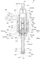
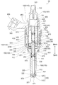
第1実施形態に係る燃料噴射弁10の構成について、図1を参照しながら説明する。燃料噴射弁10は、不図示の内燃機関に設けられ、当該内燃機関に燃料を噴射し供給するための装置である。燃料噴射弁10は、ハウジング100と、ニードル200と、可動コア300と、固定コア400と、コイル600と、を備えている。
The configuration of the fuel injection valve 10 according to the first embodiment will be described with reference to FIG. The fuel injection valve 10 is a device for injecting and supplying fuel to an internal combustion engine (not shown). The fuel injection valve 10 includes a housing 100, a needle 200, a movable core 300, a fixed core 400, and a coil 600.
ハウジング100は、その全体が概ね筒状の容器として形成された部材である。図1では、ハウジング100がその長手方向を上下方向に沿わせた状態が描かれている。尚、以下の説明においては、図1における上方側を示すものとして、単に「上方側」等の語を用いることがある。また、図1における下方側を示すものとして、単に「下方側」等の語を用いることがある。後の説明に用いる図2乃至図7においても同様である。
The housing 100 is a member formed as a generally cylindrical container. In FIG. 1, the housing 100 is depicted with its longitudinal direction along the vertical direction. In the following description, words such as “upper side” may be simply used to indicate the upper side in FIG. Further, in order to indicate the lower side in FIG. 1, a word such as “lower side” may be simply used. The same applies to FIGS. 2 to 7 used for later explanation.
後に説明するように、燃料噴射弁10から噴射される燃料は、ハウジング100の内部を上方側から下方側に向かって流れる。後述のニードル200、可動コア300、及び固定コア400は、いずれのハウジング100の内部に収容されている。
As will be described later, the fuel injected from the fuel injection valve 10 flows from the upper side to the lower side in the housing 100. A needle 200, a movable core 300, and a fixed core 400, which will be described later, are accommodated in any housing 100.
ハウジング100は、第1筒状部材110と、第2筒状部材120と、第3筒状部材130と、第4筒状部材140と、第5筒状部材150と、を有している。これらはいずれも略円筒状の部材として形成されており、それぞれの中心軸を互いに一致させた状態で配置されている。
The housing 100 includes a first tubular member 110, a second tubular member 120, a third tubular member 130, a fourth tubular member 140, and a fifth tubular member 150. These are all formed as substantially cylindrical members, and are arranged in a state in which the respective central axes coincide with each other.
第1筒状部材110は、ハウジング100のうち、燃料の流れる方向に沿って最も下流側となる位置に配置された部材である。第1筒状部材110はマルテンサイト系ステンレスによって形成されており、その硬度を高めるために焼き入れ処理が施されている。第1筒状部材110の内部には空間111が形成されており、この空間111に後述のニードル200が収容されている。
The first cylindrical member 110 is a member disposed in the housing 100 at a position on the most downstream side in the fuel flow direction. The first tubular member 110 is made of martensitic stainless steel and is subjected to a quenching process in order to increase its hardness. A space 111 is formed inside the first tubular member 110, and a later-described needle 200 is accommodated in the space 111.
第1筒状部材110の下端部では、噴射ノズル500が内側に圧入され溶接されている。噴射ノズル500はハウジング100の一部をなすものであって、円筒部520と閉塞部510とを有している。円筒部520は円筒状に形成された部分である。円筒部520は、その中心軸を第1筒状部材110の中心軸と一致させた状態で、第1筒状部材110の内側に嵌め込まれている。円筒部520の内周面521は、ニードル200の摺接部222(後述)が当接した状態で摺動する面となっている。
At the lower end of the first cylindrical member 110, the injection nozzle 500 is press-fitted inward and welded. The injection nozzle 500 forms a part of the housing 100 and has a cylindrical portion 520 and a closing portion 510. The cylindrical portion 520 is a portion formed in a cylindrical shape. The cylindrical portion 520 is fitted inside the first cylindrical member 110 in a state where the central axis thereof coincides with the central axis of the first cylindrical member 110. An inner peripheral surface 521 of the cylindrical portion 520 is a surface that slides in a state in which a sliding contact portion 222 (described later) of the needle 200 is in contact.
閉塞部510は、円筒部520のうち下方側の端部を塞ぐように形成された部分である。閉塞部510には噴孔511が形成されている。噴孔511は、閉塞部510の中心を図1の上下方向に貫くように形成された貫通穴である。噴孔511によって、第1筒状部材110の内部の空間111と外部空間とが連通されている。噴孔511は、燃料噴射弁10から噴射される燃料の出口として形成されている。このように、燃料噴射弁10では、燃料を噴射するための噴孔511が、ハウジング100の長手方向における一端に形成されている。
The closing portion 510 is a portion formed so as to close the lower end portion of the cylindrical portion 520. A nozzle hole 511 is formed in the closing portion 510. The nozzle hole 511 is a through hole formed so as to penetrate the center of the closing portion 510 in the vertical direction of FIG. Through the nozzle hole 511, the space 111 inside the first tubular member 110 and the external space communicate with each other. The nozzle hole 511 is formed as an outlet for fuel injected from the fuel injection valve 10. As described above, in the fuel injection valve 10, the injection hole 511 for injecting fuel is formed at one end in the longitudinal direction of the housing 100.
閉塞部510の内面には、噴孔511の周囲を囲むように弁座512が形成されている。弁座512は、噴孔511を塞ぐために、ニードル200のシール部221(後述)が当接する部分である。
A valve seat 512 is formed on the inner surface of the closing portion 510 so as to surround the periphery of the injection hole 511. The valve seat 512 is a portion with which a seal portion 221 (described later) of the needle 200 abuts in order to close the nozzle hole 511.
噴射ノズル500は、その全体がマルテンサイト系ステンレスによって形成されており、その硬度を高めるために焼き入れ処理が施されている。また、噴射ノズル500のうちニードル200が当接する部分、すなわち弁座512と内周面521とには、窒化処理が施されている。内周面521には、摩擦力を低下させるためのDLCコートが更に施されている。
The injection nozzle 500 is entirely formed of martensitic stainless steel, and is subjected to a quenching process in order to increase its hardness. Further, the portion of the injection nozzle 500 with which the needle 200 abuts, that is, the valve seat 512 and the inner peripheral surface 521 are subjected to nitriding treatment. The inner peripheral surface 521 is further provided with a DLC coat for reducing the frictional force.
第1筒状部材110のうち噴射ノズル500とは反対側(つまり上方側)の部分は拡径されており、当該部分から更に上方側に向かって伸びるように拡径円筒部112が形成されている。拡径円筒部112の内面は、後に説明するように可動コア300の一部が当接した状態で摺動する部分となっている。このため、拡径円筒部112には窒化処理が施されている。拡径円筒部112の上端(つまり第1筒状部材110の上端)には、第2筒状部材120の下端が接続されている。
The portion of the first cylindrical member 110 on the side opposite to the injection nozzle 500 (that is, the upper side) is enlarged in diameter, and the enlarged cylindrical portion 112 is formed so as to extend further upward from the portion. Yes. As will be described later, the inner surface of the enlarged diameter cylindrical portion 112 is a portion that slides in a state where a part of the movable core 300 is in contact. For this reason, the enlarged diameter cylindrical portion 112 is subjected to nitriding treatment. The lower end of the second cylindrical member 120 is connected to the upper end of the enlarged diameter cylindrical portion 112 (that is, the upper end of the first cylindrical member 110).
第2筒状部材120は、ハウジング100のうち、燃料の流れる方向に沿って第1筒状部材110の上流側となる位置に配置された円筒形状の部材である。第2筒状部材120の内径及び外径は、拡径円筒部112の内径及び外径とそれぞれ等しい。第2筒状部材120は、磁性体であるフェライト系ステンレスによって形成されている。第2筒状部材120の上端には、第3筒状部材130の下端が接続されている。
The second tubular member 120 is a cylindrical member disposed in the housing 100 at a position on the upstream side of the first tubular member 110 along the fuel flow direction. The inner diameter and the outer diameter of the second cylindrical member 120 are equal to the inner diameter and the outer diameter of the expanded cylindrical portion 112, respectively. The 2nd cylindrical member 120 is formed with the ferrite type stainless steel which is a magnetic body. The lower end of the third cylindrical member 130 is connected to the upper end of the second cylindrical member 120.
第3筒状部材130は、ハウジング100のうち、燃料の流れる方向に沿って第2筒状部材120の上流側となる位置に配置された円筒形状の部材である。第3筒状部材130の内径及び外径は、第2筒状部材120の内径及び外径とそれぞれ等しい。第3筒状部材130は、非磁性体であるオーステナイト系ステンレスによって形成されている。第3筒状部材130の上端には、第4筒状部材140の下端が接続されている。
The third cylindrical member 130 is a cylindrical member arranged in a position on the upstream side of the second cylindrical member 120 along the fuel flow direction in the housing 100. The inner diameter and the outer diameter of the third cylindrical member 130 are equal to the inner diameter and the outer diameter of the second cylindrical member 120, respectively. The third cylindrical member 130 is made of austenitic stainless steel that is a nonmagnetic material. The lower end of the fourth cylindrical member 140 is connected to the upper end of the third cylindrical member 130.
第4筒状部材140は、ハウジング100のうち、燃料の流れる方向に沿って第3筒状部材130の上流側となる位置に配置された円筒形状の部材である。第4筒状部材140の内径及び外径は、第3筒状部材130の内径及び外径とそれぞれ等しい。第4筒状部材140は、磁性体であるフェライト系ステンレスによって形成されている。第4筒状部材140の上方側部分では、第5筒状部材150の下端部分が内側に圧入され溶接されている。
The fourth tubular member 140 is a cylindrical member disposed in the housing 100 at a position on the upstream side of the third tubular member 130 along the fuel flow direction. The inner diameter and outer diameter of the fourth cylindrical member 140 are equal to the inner diameter and outer diameter of the third cylindrical member 130, respectively. The fourth cylindrical member 140 is made of a ferritic stainless steel that is a magnetic material. At the upper side portion of the fourth cylindrical member 140, the lower end portion of the fifth cylindrical member 150 is press-fitted inward and welded.
第5筒状部材150は、ハウジング100のうち、燃料の流れる方向に沿って最も上流側となる位置に配置された略円筒形状の部材である。第5筒状部材150はオーステナイト系ステンレスによって形成されている。第5筒状部材150の上端部には導入口153が形成されている。導入口153は、外部から導入される燃料の入口として形成された開口である。
The fifth cylindrical member 150 is a substantially cylindrical member disposed at a position on the most upstream side in the fuel flow direction in the housing 100. The fifth cylindrical member 150 is made of austenitic stainless steel. An inlet 153 is formed at the upper end of the fifth cylindrical member 150. The inlet 153 is an opening formed as an inlet for fuel introduced from the outside.
第5筒状部材150の内部に形成された空間151のうち、導入口153の近傍となる位置には、フィルタ152が設けられている。フィルタ152は、導入口153から導入された燃料に含まれる異物を捕集するためのものである。
A filter 152 is provided at a position in the vicinity of the inlet 153 in the space 151 formed inside the fifth cylindrical member 150. The filter 152 is for collecting foreign substances contained in the fuel introduced from the introduction port 153.
ニードル200は、ハウジング100の内部に配置された棒状の部材である。ニードル200は、その中心軸をハウジング100の中心軸に移動させた状態で、ハウジング100の長手方向(図1では上下方向)に沿って移動可能な状態で配置されている。ニードル200はマルテンサイト系ステンレスによって形成されており、硬度を高めるために焼き入れ処理が施されている。ニードル200のうち噴射ノズル500側の端部には、シール部221が形成されている。
The needle 200 is a rod-shaped member disposed inside the housing 100. The needle 200 is arranged so as to be movable along the longitudinal direction (vertical direction in FIG. 1) of the housing 100 with its central axis moved to the central axis of the housing 100. The needle 200 is made of martensitic stainless steel and is subjected to a quenching process to increase the hardness. A seal portion 221 is formed at the end of the needle 200 on the injection nozzle 500 side.
ニードル200が可動範囲のうち最も下方側まで移動すると、図1に示されるようにシール部221が弁座512に当接し、噴孔511が閉じられた状態となる。これにより、噴孔511からの燃料の噴射が停止される。ニードル200が上方側に移動し、シール部221が弁座512から離れると、噴孔511が開かれた状態となる。これにより、噴孔511からの燃料の噴射が行われる。このように、ニードル200は、ハウジング100の内部において長手方向に沿って移動することにより、噴孔511の開閉を切り換えるための部材として設けられている。
When the needle 200 moves to the lowermost side in the movable range, the seal portion 221 contacts the valve seat 512 and the injection hole 511 is closed as shown in FIG. Thereby, the fuel injection from the nozzle hole 511 is stopped. When the needle 200 moves upward and the seal portion 221 moves away from the valve seat 512, the nozzle hole 511 is opened. As a result, fuel is injected from the injection hole 511. Thus, the needle 200 is provided as a member for switching the opening / closing of the nozzle hole 511 by moving along the longitudinal direction inside the housing 100.
以下の説明においては、噴孔511が開かれるようにニードル200が移動する方向の側、すなわち図1における上側のことを、「開弁側」とも称することがある。また、噴孔511が閉じられるようにニードル200が移動する方向の側、すなわち図1における下側のことを、「閉弁側」とも称することがある。
In the following description, the side in the direction in which the needle 200 moves so that the nozzle hole 511 is opened, that is, the upper side in FIG. Further, the side in which the needle 200 moves so that the nozzle hole 511 is closed, that is, the lower side in FIG. 1 may be referred to as a “valve closing side”.
ニードル200の側面のうち、シール部221よりも僅かに開弁側となる位置には、外方に向けて突出する摺接部222が複数形成されている。摺接部222は、その先端を円筒部520の内周面521に当接させた状態で摺動する部分である。複数の摺接部222は、ニードル200の周方向に沿って並ぶように形成されている。互いに隣り合う摺接部222同士の間には、燃料が通るための経路として凹部223が形成されている。ニードル200のうちシール部221及び摺接部222には、窒化処理が施されている。摺接部222には更にDLCコートが施されている。これにより、摺接部222と内周面521との間における摩擦抵抗が低下している。
In the side surface of the needle 200, a plurality of sliding contact portions 222 projecting outward are formed at positions slightly closer to the valve opening side than the seal portion 221. The sliding contact portion 222 is a portion that slides in a state in which the tip thereof is in contact with the inner peripheral surface 521 of the cylindrical portion 520. The plurality of sliding contact portions 222 are formed so as to be aligned along the circumferential direction of the needle 200. A recess 223 is formed between the sliding contact portions 222 adjacent to each other as a path for fuel to pass. Of the needle 200, the seal portion 221 and the sliding contact portion 222 are subjected to nitriding treatment. The sliding contact portion 222 is further provided with a DLC coat. Thereby, the frictional resistance between the sliding contact part 222 and the inner peripheral surface 521 is reduced.
ニードル200は、後に説明する可動コア300を上下方向に貫いた状態で配置されている。ニードル200の上端部は、可動コア300の上端よりも更に上方側に配置されている。ニードル200の上端部分における側面には、外方に向けて突出するように大径部210が形成されている。大径部210のうち可動コア300側(閉弁側)の面は、可動コア300の端面に当接している。
The needle 200 is disposed in a state of penetrating a movable core 300, which will be described later, in the vertical direction. The upper end portion of the needle 200 is disposed further above the upper end of the movable core 300. A large-diameter portion 210 is formed on the side surface of the upper end portion of the needle 200 so as to protrude outward. The surface on the movable core 300 side (valve closing side) of the large diameter portion 210 is in contact with the end surface of the movable core 300.
ニードル200の内部には空間201が形成されている。空間201は、ニードル200のうち大径部210の開弁側端部から、可動コア300よりも閉弁側となる位置まで伸びるように形成されている。ニードル200のうち開弁側の端部では、空間201が外部に開放されている。空間201のうち可動コア300よりも閉弁側となる位置では、ニードル200に貫通穴202が形成されている。この貫通穴202により、空間201と空間111とが連通されている。
A space 201 is formed inside the needle 200. The space 201 is formed so as to extend from the valve opening side end of the large diameter portion 210 of the needle 200 to a position closer to the valve closing side than the movable core 300. A space 201 is open to the outside at the end of the needle 200 on the valve opening side. A through hole 202 is formed in the needle 200 at a position closer to the valve closing side than the movable core 300 in the space 201. The space 201 and the space 111 are communicated with each other through the through hole 202.
可動コア300は、その全体が略円柱形状に形成された部材である。可動コア300は、その中心軸をハウジング100の中心軸に移動させた状態で、ニードル200と共にハウジング100の長手方向(図1では上下方向)に沿って移動可能な状態で配置されている。可動コア300は、可動側高硬度部310と可動側低硬度部320とを有している。
The movable core 300 is a member that is formed in a substantially cylindrical shape as a whole. The movable core 300 is arranged so as to be movable along the longitudinal direction (vertical direction in FIG. 1) of the housing 100 together with the needle 200 with the central axis thereof being moved to the central axis of the housing 100. The movable core 300 has a movable high hardness part 310 and a movable low hardness part 320.
可動側高硬度部310は、その一部(後述の拡径部311を除く部分)が可動側低硬度部320よりも内側となる位置に配置された略円筒形状の部分である。可動側高硬度部310は、非磁性体であり且つ比較的硬度の高い材料であるマルテンサイト系ステンレスによって形成されている。可動側高硬度部310には、その硬度を高めるために焼き入れ処理が施されている。可動側高硬度部310の中央には、これを上下方向(つまりハウジング100の長手方向)に貫くように可動側貫通穴313が形成されている。先に説明したニードル200は、この可動側貫通穴313に挿通されている。ニードル200の外側面は、可動側貫通穴313の内面に当接した状態で摺動可能となっている。可動側貫通穴313の内面には窒化処理が施されている。また、ニードル200の外側面にも窒化処理が施されており、更にDLCコートが施されている。
The movable-side high hardness portion 310 is a substantially cylindrical portion disposed at a position where a part thereof (a portion excluding a diameter-expanded portion 311 described later) is located inside the movable-side low hardness portion 320. The movable high hardness part 310 is made of martensitic stainless steel, which is a non-magnetic material and has a relatively high hardness. The movable high hardness part 310 is subjected to a quenching process in order to increase its hardness. A movable side through hole 313 is formed at the center of the movable side high hardness portion 310 so as to penetrate the movable side high hardness portion 310 in the vertical direction (that is, the longitudinal direction of the housing 100). The needle 200 described above is inserted into the movable side through hole 313. The outer surface of the needle 200 is slidable in contact with the inner surface of the movable through hole 313. The inner surface of the movable side through hole 313 is nitrided. Further, the outer surface of the needle 200 is nitrided and further DLC coated.
可動側高硬度部310のうち開弁側の端面には、ニードル200の大径部210が上方側から当接している。尚、可動側高硬度部310の開弁側の端面の一部は、後に説明するように、開弁時において固定コア400に当たる部分となっている。可動側高硬度部310の開弁側の端面では、ニードル200の大径部210が当接する部分と、固定コア400に当たる部分と、のそれぞれに対して窒化処理が施されている。また、大径部210のうち閉弁側の端面にも窒化処理が施されている。
The large-diameter portion 210 of the needle 200 is in contact with the end surface on the valve opening side of the movable high hardness portion 310 from above. A part of the end face on the valve opening side of the movable high hardness part 310 is a part that contacts the fixed core 400 when the valve is opened, as will be described later. On the end surface of the movable high hardness portion 310 on the valve opening side, nitriding is performed on each of the portion where the large diameter portion 210 of the needle 200 abuts and the portion that contacts the fixed core 400. Further, the end face on the valve closing side of the large diameter portion 210 is also subjected to nitriding treatment.
可動側高硬度部310のうち閉弁側の部分は拡径されており、側方に向けて突出する拡径部311が形成されている。拡径部311の先端面312は、第1筒状部材110のうち拡径円筒部112の内面に当接している。可動コア300が移動する際には、拡径部311の先端面312が拡径円筒部112の内面に当接した状態で摺動する。先端面312には窒化処理が施されており、更にDLCコートが施されている。
The portion on the valve closing side of the movable side high hardness portion 310 is enlarged in diameter, and an enlarged diameter portion 311 protruding toward the side is formed. The distal end surface 312 of the enlarged diameter portion 311 is in contact with the inner surface of the enlarged diameter cylindrical portion 112 of the first cylindrical member 110. When the movable core 300 moves, the distal end surface 312 of the enlarged diameter portion 311 slides in a state where it is in contact with the inner surface of the enlarged diameter cylindrical portion 112. The tip surface 312 is nitrided and further DLC coated.
可動側低硬度部320は、可動側高硬度部310よりも外側となる位置に配置された略円筒形状の部分である。可動側低硬度部320は、その内面を可動側高硬度部310の外面に当接させた状態で、可動側高硬度部310に対し所謂「打ち込み」によって固定されている。可動側低硬度部320の閉弁側の端面は、可動側高硬度部310の拡径部311に当接している。
The movable-side low hardness portion 320 is a substantially cylindrical portion disposed at a position outside the movable-side high hardness portion 310. The movable-side low hardness portion 320 is fixed to the movable-side high hardness portion 310 by so-called “driving” in a state where the inner surface thereof is in contact with the outer surface of the movable-side high hardness portion 310. The end surface on the valve closing side of the movable-side low hardness portion 320 is in contact with the enlarged diameter portion 311 of the movable-side high hardness portion 310.
可動側低硬度部320は、磁性体であるフェライト系ステンレスによって形成されている。その結果、可動側低硬度部320は、可動側高硬度部310よりも硬が低い部分となっている。ハウジング100の内部において可動側低硬度部320が配置されている位置は、第2筒状部材120と概ね対向する位置となっている。
The movable-side low-hardness portion 320 is made of a ferritic stainless steel that is a magnetic material. As a result, the movable-side low hardness portion 320 is a portion having a lower hardness than the movable-side high hardness portion 310. The position where the movable-side low-hardness portion 320 is disposed inside the housing 100 is a position that generally faces the second tubular member 120.
可動側低硬度部320の開弁側の端面の位置は、可動側高硬度部310の開弁側の端面の位置よりも、僅かに閉弁側となっている。換言すれば、可動側高硬度部310の上端面は、可動側低硬度部320の上端面よりも僅かに上方側(固定コア400側)に向けて突出している。
The position of the end face on the valve opening side of the movable side low hardness part 320 is slightly closer to the valve closing side than the position of the end face on the valve opening side of the movable side high hardness part 310. In other words, the upper end surface of the movable high hardness portion 310 protrudes slightly upward (on the fixed core 400 side) from the upper end surface of the movable low hardness portion 320.
その結果、可動側高硬度部310は、可動コア300のうち、ハウジング100の長手方向に沿った一方側の端部(つまり上端部)から他方側の端部(つまり下端部)まで伸びるように形成されている。
As a result, in the movable core 300, the movable-side high hardness portion 310 extends from one end portion (that is, the upper end portion) along the longitudinal direction of the housing 100 to the other end portion (that is, the lower end portion). Is formed.
可動コア300のうち外周部近くとなる位置には、可動コア300を上下方向に沿って貫く貫通穴301が複数形成されている。それぞれの貫通穴301は、可動側高硬度部310の拡径部311と、可動側低硬度部320との両方を貫くように形成されている。貫通穴301の機能については後述する。
A plurality of through holes 301 penetrating the movable core 300 along the vertical direction are formed at positions near the outer periphery of the movable core 300. Each through hole 301 is formed so as to penetrate both the enlarged diameter portion 311 of the movable-side high hardness portion 310 and the movable-side low hardness portion 320. The function of the through hole 301 will be described later.
尚、本実施形態では上記のように、可動コア300の一部である可動側低硬度部320が磁性体によって形成されており、その他の部分である可動側高硬度部310が非磁性体によって形成されている。このような態様に替えて、可動コア300の全体が磁性体によって形成されているような態様であってもよい。ただしこの場合でも、可動側高硬度部310は、可動側低硬度部320よりも硬度の高い材料で形成される。
In the present embodiment, as described above, the movable-side low hardness portion 320 that is a part of the movable core 300 is formed of a magnetic material, and the movable-side high hardness portion 310 that is the other portion is formed of a nonmagnetic material. Is formed. It may replace with such an aspect and the aspect that the whole movable core 300 is formed with the magnetic body may be sufficient. However, even in this case, the movable-side high hardness portion 310 is formed of a material having a higher hardness than the movable-side low hardness portion 320.
固定コア400は、可動コア300と同様に、その全体が略円柱形状に形成された部材である。固定コア400は、その中心軸をハウジング100の中心軸に移動させた状態で、ハウジング100の内部に固定されている。固定コア400が設けられている位置は、開弁側において可動コア300と隣り合う位置である。図1のようにニードル200のシール部221が弁座512に当接しているときにおいては、固定コア400と可動コア300との間には隙間が形成されている。固定コア400は、固定側高硬度部410と固定側低硬度部420とを有している。
The fixed core 400 is a member formed in a substantially cylindrical shape as a whole, like the movable core 300. The fixed core 400 is fixed inside the housing 100 with its central axis moved to the central axis of the housing 100. The position where the fixed core 400 is provided is a position adjacent to the movable core 300 on the valve opening side. As shown in FIG. 1, when the seal portion 221 of the needle 200 is in contact with the valve seat 512, a gap is formed between the fixed core 400 and the movable core 300. The fixed core 400 has a fixed-side high hardness portion 410 and a fixed-side low hardness portion 420.
固定側高硬度部410は、固定側低硬度部420よりも内側となる位置に配置された略円筒形状の部分である。固定側高硬度部410は、非磁性体であり且つ比較的硬度の高い材料であるマルテンサイト系ステンレスによって形成されている。固定側高硬度部410には、その硬度を高めるために焼き入れ処理が施されている。固定側高硬度部410のうち可動コア300側の端面は、可動コア300の可動側高硬度部310が当たる部分となっている。このため、当該端面には窒化処理が施されている。
The fixed-side high hardness portion 410 is a substantially cylindrical portion disposed at a position inside the fixed-side low hardness portion 420. The fixed-side high hardness portion 410 is made of martensitic stainless steel that is a non-magnetic material and has a relatively high hardness. The fixed-side high hardness portion 410 is subjected to quenching treatment to increase its hardness. The end surface on the movable core 300 side of the fixed-side high hardness portion 410 is a portion where the movable-side high hardness portion 310 of the movable core 300 hits. For this reason, the end face is subjected to nitriding treatment.
固定側高硬度部410の中央には、これを上下方向(つまりハウジング100の長手方向)に貫くように固定側貫通穴401が形成されている。先に説明したニードル200の空間201は、この固定側貫通穴401によって第5筒状部材150の空間151に連通されている。固定側高硬度部410の上端部分における側面には、外方に向けて突出するように拡径部411が形成されている。
A fixed-side through hole 401 is formed at the center of the fixed-side high hardness portion 410 so as to penetrate the fixed-side high hardness portion 410 in the vertical direction (that is, the longitudinal direction of the housing 100). The space 201 of the needle 200 described above is communicated with the space 151 of the fifth cylindrical member 150 through the fixed side through hole 401. An enlarged diameter portion 411 is formed on the side surface of the upper end portion of the fixed-side high hardness portion 410 so as to protrude outward.
固定側貫通穴401のうち可動コア300側の部分には、ニードル200の大径部210が下方から挿通されている。図1に示されるように、当該部分における固定側貫通穴401の内径は、他の部分における固定側貫通穴401の内径よりも大きくなっている。このため、ニードル200の大径部210と、固定側貫通穴401の内面との間には隙間が形成されている。
The large diameter portion 210 of the needle 200 is inserted from below into the portion on the movable core 300 side of the fixed side through hole 401. As shown in FIG. 1, the inner diameter of the fixed side through hole 401 in the portion is larger than the inner diameter of the fixed side through hole 401 in the other portion. For this reason, a gap is formed between the large diameter portion 210 of the needle 200 and the inner surface of the fixed side through hole 401.
固定側低硬度部420は、その全体が固定側高硬度部410よりも外側となる位置に配置された略円筒形状の部分である。固定側低硬度部420は、その内面を固定側高硬度部410の外面に当接させた状態で、固定側高硬度部410に対して溶接によって固定されている。本実施形態では、固定コア400の開弁側端部となる位置において、固定側高硬度部410と固定側低硬度部420とが互いに溶接されている。
The fixed-side low hardness portion 420 is a substantially cylindrical portion that is disposed at a position that is entirely outside the fixed-side high hardness portion 410. The fixed-side low hardness portion 420 is fixed to the fixed-side high hardness portion 410 by welding in a state where the inner surface thereof is in contact with the outer surface of the fixed-side high hardness portion 410. In the present embodiment, the fixed-side high hardness portion 410 and the fixed-side low hardness portion 420 are welded to each other at a position that becomes the valve opening side end portion of the fixed core 400.
固定側低硬度部420は、磁性体であるフェライト系ステンレスによって形成されている。その結果、固定側低硬度部420は、固定側高硬度部410よりも硬が低い部分となっている。ハウジング100の内部において固定側低硬度部420が配置されている位置は、第4筒状部材140と概ね対向する位置となっている。固定側低硬度部420の外側面は、第4筒状部材140の内面に対して溶接によって固定されている。
The fixed-side low-hardness portion 420 is made of a ferrite stainless steel that is a magnetic material. As a result, the fixed-side low hardness portion 420 is a portion having a lower hardness than the fixed-side high hardness portion 410. The position where the fixed-side low hardness portion 420 is disposed inside the housing 100 is a position that generally faces the fourth cylindrical member 140. The outer surface of the fixed-side low hardness portion 420 is fixed to the inner surface of the fourth tubular member 140 by welding.
固定側低硬度部420の開弁側の端面の位置は、固定側高硬度部410の開弁側の端面の位置と同一となっている。また、固定側低硬度部420の閉弁側の端面の位置は、固定側高硬度部410の閉弁側の端面の位置よりも、僅かに開弁側となっている。換言すれば、固定側高硬度部410の下端面は、固定側低硬度部420の下端面よりも僅かに下方側(可動コア300側)に向けて突出している。
The position of the end face on the valve opening side of the fixed low hardness part 420 is the same as the position of the end face on the valve opening side of the fixed high hardness part 410. Further, the position of the end face on the valve closing side of the fixed low hardness portion 420 is slightly on the valve opening side than the position of the end face on the valve closing side of the fixed high hardness portion 410. In other words, the lower end surface of the fixed-side high hardness portion 410 protrudes slightly downward (movable core 300 side) from the lower end surface of the fixed-side low hardness portion 420.
その結果、固定側高硬度部410は、固定コア400のうち、ハウジング100の長手方向に沿った一方側の端部(つまり上端部)から他方側の端部(つまり下端部)まで伸びるように形成されている。固定側高硬度部410の下端面は、その全体が、可動側高硬度部310の上端面に対向している。
As a result, in the fixed core 400, the fixed-side high hardness portion 410 extends from one end (that is, the upper end) along the longitudinal direction of the housing 100 to the other end (that is, the lower end). Is formed. The lower end surface of the fixed-side high hardness portion 410 is entirely opposed to the upper end surface of the movable-side high hardness portion 310.
尚、本実施形態では上記のように、固定コア400の一部である固定側低硬度部420が磁性体によって形成されており、その他の部分である固定側高硬度部410が非磁性体によって形成されている。このような態様に替えて、固定コア400の全体が磁性体によって形成されているような態様であってもよい。ただしこの場合でも、固定側高硬度部410は、固定側低硬度部420よりも硬度の高い材料で形成される。
In the present embodiment, as described above, the fixed-side low hardness portion 420 that is a part of the fixed core 400 is formed of a magnetic material, and the fixed-side high hardness portion 410 that is the other portion is formed of a nonmagnetic material. Is formed. It may replace with such an aspect and the aspect that the whole fixed core 400 is formed with the magnetic body may be sufficient. However, even in this case, the fixed-side high hardness portion 410 is formed of a material having a higher hardness than the fixed-side low hardness portion 420.
コイル600は、電流の供給を受けて磁力を生じさせるものである。コイル600はボビン610に巻かれた状態で、ハウジング100のうち第3筒状部材130の全体と、第4筒状部材140の一部とを外側から覆うように配置されている。コイル600に電流が供給されると、固定側低硬度部420、可動側低硬度部320、第2筒状部材120、及び第4筒状部材140等を磁束が通るように磁気回路が形成される。その結果として、固定コア400と可動コア300との間に磁気吸引力が発生する。この磁気吸引力によって、可動コア300は、ニードル200と共に開弁側に移動する。コイル600に対する電流の供給が停止すると、上記の磁気吸引力は0となる。その際、可動コア300は、後述のスプリング820の付勢力によって、ニードル200と共に閉弁側に移動する。
The coil 600 generates a magnetic force upon receiving a current. The coil 600 is wound around the bobbin 610 and is disposed so as to cover the entire third cylindrical member 130 and a part of the fourth cylindrical member 140 in the housing 100 from the outside. When a current is supplied to the coil 600, a magnetic circuit is formed so that the magnetic flux passes through the fixed low hardness portion 420, the movable low hardness portion 320, the second cylindrical member 120, the fourth cylindrical member 140, and the like. The As a result, a magnetic attractive force is generated between the fixed core 400 and the movable core 300. Due to this magnetic attractive force, the movable core 300 moves to the valve opening side together with the needle 200. When the current supply to the coil 600 is stopped, the magnetic attraction force becomes zero. At that time, the movable core 300 moves to the valve closing side together with the needle 200 by a biasing force of a spring 820 described later.
燃料噴射弁10のその他の構成について説明する。固定側高硬度部410に形成された固定側貫通穴401の上方側部分には、アジャスティングパイプ430が圧入され固定されている。アジャスティングパイプ430は円筒形状の部材であって、その内側には、アジャスティングパイプ430を上下方向に貫く貫通穴431が形成されている。
The other configuration of the fuel injection valve 10 will be described. An adjusting pipe 430 is press-fitted and fixed to an upper portion of the fixed side through hole 401 formed in the fixed side high hardness portion 410. The adjusting pipe 430 is a cylindrical member, and a through hole 431 passing through the adjusting pipe 430 in the vertical direction is formed inside thereof.
固定側貫通穴401のうちアジャスティングパイプ430の下方側には、スプリング820が配置されている。スプリング820は、その伸縮方向が上下方向に沿っている弾性部材である。スプリング820の一端は、アジャスティングパイプ430の閉弁側端部に当接している。スプリング820の他端は、ニードル200のうち大径部210の開弁側端部に当接している。スプリング820は、その長さを自由長よりも短くした状態となっている。このため、ニードル200の大径部210は、スプリング820からの力によって可動側高硬度部310に対して押し付けられている。その結果、スプリング820は、ニードル200と可動コア300との両方を閉弁側に付勢している。
A spring 820 is disposed below the adjusting pipe 430 in the fixed side through hole 401. The spring 820 is an elastic member whose expansion / contraction direction is along the vertical direction. One end of the spring 820 is in contact with the valve closing side end of the adjusting pipe 430. The other end of the spring 820 is in contact with the valve opening side end of the large diameter portion 210 of the needle 200. The spring 820 is in a state where its length is shorter than the free length. For this reason, the large-diameter portion 210 of the needle 200 is pressed against the movable high hardness portion 310 by the force from the spring 820. As a result, the spring 820 biases both the needle 200 and the movable core 300 toward the valve closing side.
可動コア300の下方側には、スプリング810が配置されている。スプリング810は、その伸縮方向が上下方向に沿っている弾性部材である。スプリング810の一端は、可動側高硬度部310の閉弁側端面に形成された段差部に当接している。スプリング810の他端は、第1筒状部材110のうち開弁側の端部近傍に形成された段差部に当接している。
A spring 810 is disposed below the movable core 300. The spring 810 is an elastic member whose expansion / contraction direction is along the vertical direction. One end of the spring 810 is in contact with a step portion formed on the valve-closing end surface of the movable high hardness portion 310. The other end of the spring 810 is in contact with a step portion formed in the vicinity of the end portion on the valve opening side of the first tubular member 110.
スプリング810は、その長さを自由長よりも短くした状態となっている。このため、可動コア300の可動側高硬度部310は、スプリング810からの力によってニードル200の大径部210に対して押し付けられている。その結果、スプリング810は、ニードル200と可動コア300との両方を開弁側に付勢している。スプリング810とスプリング820とが設けられていることにより、大径部210と可動側高硬度部310とが互いに当接している状態が維持されている。
The spring 810 is in a state where its length is shorter than the free length. For this reason, the movable high hardness portion 310 of the movable core 300 is pressed against the large diameter portion 210 of the needle 200 by the force from the spring 810. As a result, the spring 810 biases both the needle 200 and the movable core 300 toward the valve opening side. By providing the spring 810 and the spring 820, the state in which the large diameter portion 210 and the movable high hardness portion 310 are in contact with each other is maintained.
本実施形態では、スプリング820の付勢力が、スプリング810の付勢力よりも大きくなっている。このため、コイル600に対する電流の供給が停止しており、固定コア400と可動コア300との間に磁気吸引力が発生していないときには、ニードル200のシール部221が弁座512に当接した状態、すなわち噴孔511が塞がれた状態となる。
In this embodiment, the urging force of the spring 820 is larger than the urging force of the spring 810. For this reason, when the supply of current to the coil 600 is stopped and no magnetic attractive force is generated between the fixed core 400 and the movable core 300, the seal portion 221 of the needle 200 contacts the valve seat 512. The state, that is, the state where the nozzle hole 511 is closed.
コイル600、第4筒状部材140、及び第5筒状部材150の一部は、樹脂900によって外側からモールドされている。この樹脂900の一部は外側に向かって突出しており、この突出した部分がコネクタ910として形成されている。コネクタ910は、コイル600に対して電流を供給するための線が接続される部分である。コネクタ910の内側には給電端子920が配置されている。給電端子920は、コイル600に繋がる給電線の一端に設けられた端子である。コイル600への電流の供給はこの給電端子920から行われる。
Part of the coil 600, the fourth cylindrical member 140, and the fifth cylindrical member 150 is molded from the outside with a resin 900. A part of the resin 900 protrudes outward, and this protruding portion is formed as a connector 910. The connector 910 is a part to which a wire for supplying current to the coil 600 is connected. A power supply terminal 920 is disposed inside the connector 910. The power supply terminal 920 is a terminal provided at one end of a power supply line connected to the coil 600. The current is supplied to the coil 600 from the power supply terminal 920.
樹脂900のうち、第4筒状部材140をモールドしている部分の更に外側には、ホルダ700が配置されている。ホルダ700は磁性体からなる筒状の部材であって、拡径円筒部112の外側となる位置から、コイル600の開弁側端部よりも更に開弁側となる位置まで伸びるように形成されている。ホルダ700の内側であって、且つコイル600よりも開弁側となる位置にはカバー710が配置されている。カバー710は、磁性体からなる略円管状の部材であって、第4筒状部材140を外側から囲むように配置されている。カバー710のうちコネクタ910の近傍となる部分は、コネクタ910との干渉を避けるために切り欠かれている。このため、図1においては、第4筒状部材140の右側となる位置においてのみカバー710の断面が表れている。ホルダ700及びカバー710は、コイル600で発生した磁束が通る磁気回路の一部を成すものである。
A holder 700 is disposed on the outer side of the resin 900 where the fourth tubular member 140 is molded. The holder 700 is a cylindrical member made of a magnetic material, and is formed so as to extend from a position on the outer side of the enlarged diameter cylindrical portion 112 to a position that is further on the valve opening side than the valve opening side end of the coil 600. ing. A cover 710 is disposed inside the holder 700 and at a position closer to the valve opening side than the coil 600. The cover 710 is a substantially circular tubular member made of a magnetic material, and is disposed so as to surround the fourth tubular member 140 from the outside. A portion of the cover 710 that is near the connector 910 is cut away to avoid interference with the connector 910. For this reason, in FIG. 1, the cross section of the cover 710 appears only at the position on the right side of the fourth tubular member 140. Holder 700 and cover 710 form part of a magnetic circuit through which the magnetic flux generated by coil 600 passes.
燃料噴射弁10の動作について説明する。第5筒状部材150には、導入口153から燃料が供給されている。コイル600への電流供給が行われていないときには、既に述べたように噴孔511は閉じられている。このため、燃料噴射弁10の内部は燃料によって加圧された状態となっている。
The operation of the fuel injection valve 10 will be described. Fuel is supplied to the fifth cylindrical member 150 from the inlet 153. When no current is supplied to the coil 600, the nozzle hole 511 is closed as described above. For this reason, the inside of the fuel injection valve 10 is in a state pressurized by the fuel.
コイル600への電流供給が開始されると、固定コア400と可動コア300との間に磁気吸引力が発生し、可動コア300は開弁側に移動する。その際、ニードル200の大径部210は可動コア300の可動側高硬度部310に当接しているので、可動コア300と共にニードル200も開弁側に移動する。ニードル200のシール部221が弁座512から離れて、噴孔511が開かれた状態になるので、噴孔511からの燃料の噴射が開始される。
When the current supply to the coil 600 is started, a magnetic attractive force is generated between the fixed core 400 and the movable core 300, and the movable core 300 moves to the valve opening side. At that time, since the large diameter portion 210 of the needle 200 is in contact with the movable high hardness portion 310 of the movable core 300, the needle 200 moves to the valve opening side together with the movable core 300. Since the seal portion 221 of the needle 200 is separated from the valve seat 512 and the injection hole 511 is opened, fuel injection from the injection hole 511 is started.
燃料は、導入口153から空間151に流入した後、貫通穴431、固定側貫通穴401、空間201、貫通穴202、及び空間111を順に通り、噴孔511から噴射される。
After the fuel flows into the space 151 from the introduction port 153, the fuel passes through the through hole 431, the fixed side through hole 401, the space 201, the through hole 202, and the space 111 in order, and is injected from the injection hole 511.
尚、可動コア300の周囲は、貫通穴202から排出された燃料で満たされた状態となっている。可動コア300が開弁側に移動する際には、可動コア300よりも開弁側の空間に存在していた燃料が、可動コア300を貫く貫通穴301を通って、可動コア300よりも閉弁側の空間に移動する。貫通穴301を通って燃料がスムーズに移動するので、可動コア300の移動が燃料によって妨げられてしまうことが無い。可動コア300が、その後閉弁側に移動する際においても同様である。
It should be noted that the periphery of the movable core 300 is filled with the fuel discharged from the through hole 202. When the movable core 300 moves to the valve opening side, the fuel present in the valve opening side of the movable core 300 passes through the through-hole 301 that penetrates the movable core 300 and is closed from the movable core 300. Move to the valve side space. Since the fuel moves smoothly through the through hole 301, the movement of the movable core 300 is not hindered by the fuel. The same applies when the movable core 300 moves to the valve closing side thereafter.
開弁側に移動し始めた可動コア300はその後、固定コア400に当たって止まる。本実施形態では既に述べたように、可動側高硬度部310の上端面が固定コア400側に向けて突出しており、固定側高硬度部410の下端面が可動コア300側に向けて突出している。このため、可動コア300は、可動側高硬度部310が固定コア400に当たる一方で、可動側低硬度部320は固定コア400には当たらない。また、固定コア400のうち固定側高硬度部410には可動コア300が当たるのであるが、固定側低硬度部420には可動コア300が当たらない。
The movable core 300 that has started to move toward the valve opening side then hits the fixed core 400 and stops. In the present embodiment, as already described, the upper end surface of the movable side high hardness portion 310 protrudes toward the fixed core 400 side, and the lower end surface of the fixed side high hardness portion 410 protrudes toward the movable core 300 side. Yes. For this reason, in the movable core 300, the movable side high hardness portion 310 hits the fixed core 400, while the movable side low hardness portion 320 does not hit the fixed core 400. In addition, the movable core 300 hits the fixed-side high hardness portion 410 of the fixed core 400, but the movable core 300 does not hit the fixed-side low hardness portion 420.
このように、本実施形態に係る燃料噴射弁10は、コイル600に電流が供給されると、発生した磁気吸引力によって可動コア300がニードル200と共に固定コア400側(開弁側)に移動し、可動側高硬度部310が固定側高硬度部410に当たるように構成されている。
Thus, in the fuel injection valve 10 according to the present embodiment, when a current is supplied to the coil 600, the movable core 300 moves to the fixed core 400 side (the valve opening side) together with the needle 200 by the generated magnetic attractive force. The movable high hardness portion 310 is configured to contact the fixed high hardness portion 410.
本実施形態では、可動コア300のうち比較的硬度の高い部分(可動側高硬度部310)と、固定コア400のうち比較的硬度の高い部分(固定側高硬度部410)とが互いに衝突する。このため、固定コア及び可動コアのいずれにおいても、衝突による損傷の発生が抑制される。
In this embodiment, a relatively hard portion (movable high hardness portion 310) of the movable core 300 and a relatively hard portion (fixed side high hardness portion 410) of the fixed core 400 collide with each other. . For this reason, in any of the fixed core and the movable core, occurrence of damage due to the collision is suppressed.
一方、磁気吸引力に寄与する部分である可動側低硬度部320及び固定側低硬度部420は、比較的硬度の低い磁性体によって形成されているのであるが、これらには他の部材が衝突しない構成となっている。燃料噴射弁10では、磁性体を用いて磁気吸引力を効率的に発生させ得る構成としながらも、磁性体が衝突によって損傷してしまうことが防止されている。
On the other hand, the movable-side low hardness part 320 and the fixed-side low hardness part 420, which are parts that contribute to the magnetic attractive force, are formed of a magnetic material having relatively low hardness, but other members collide with them. It has a configuration that does not. In the fuel injection valve 10, the magnetic body is prevented from being damaged by a collision while being configured to be able to efficiently generate a magnetic attractive force using the magnetic body.
可動側高硬度部310は、可動コア300のうち、ハウジング100の長手方向に沿った一方側の端部(つまり上端部)から他方側の端部(つまり下端部)まで伸びるように形成されている。このため、例えば可動側高硬度部310のうち閉弁側の端部が可動側低硬度部320によって支持されているような構成に比べると、可動コア300が固定コア400に当たった際に、可動側低硬度部320に加えられる衝撃が低減される。このため、硬度の低い可動側低硬度部320の損傷が更に防止されている。
The movable-side high-hardness portion 310 is formed so as to extend from one end (that is, the upper end) along the longitudinal direction of the housing 100 to the other end (that is, the lower end) of the movable core 300. Yes. For this reason, when the movable core 300 hits the fixed core 400, for example, compared to a configuration in which the end on the valve closing side of the movable high hardness portion 310 is supported by the movable low hardness portion 320, The impact applied to the movable side low hardness part 320 is reduced. For this reason, damage to the movable side low hardness part 320 with low hardness is further prevented.
同様に、固定側高硬度部410は、固定コア400のうち、ハウジング100の長手方向に沿った一方側の端部(つまり上端部)から他方側の端部(つまり下端部)まで伸びるように形成されている。このため、例えば固定側高硬度部410のうち開弁側の端部が固定側低硬度部420によって支持されているような構成に比べると、可動コア300が固定コア400に当たった際に、固定側低硬度部420に加えられる衝撃が低減される。このため、硬度の低い固定側低硬度部420の損傷が更に防止されている。
Similarly, the fixed-side high hardness portion 410 extends from the one end portion (that is, the upper end portion) of the fixed core 400 along the longitudinal direction of the housing 100 to the other end portion (that is, the lower end portion). Is formed. For this reason, when the movable core 300 hits the fixed core 400, for example, compared to a configuration in which the end portion on the valve opening side of the fixed-side high hardness portion 410 is supported by the fixed-side low hardness portion 420, The impact applied to the fixed-side low hardness portion 420 is reduced. For this reason, damage to the fixed-side low hardness portion 420 having low hardness is further prevented.
噴孔511が開かれている状態で、コイル600への電流供給が停止されると、固定コア400と可動コア300との間に磁気吸引力が働かなくなる。可動コア300及びニードル200は、スプリング820の付勢力によって閉弁側に移動し、最終的にはシール部221が弁座512に当接した状態、すなわち噴孔511が塞がれた状態となる。これにより、噴孔511からの燃料の噴射が停止する。
When the current supply to the coil 600 is stopped while the nozzle hole 511 is opened, the magnetic attractive force does not work between the fixed core 400 and the movable core 300. The movable core 300 and the needle 200 move to the valve closing side by the urging force of the spring 820, and finally the seal portion 221 is in contact with the valve seat 512, that is, the injection hole 511 is closed. . Thereby, the fuel injection from the nozzle hole 511 is stopped.
本実施形態では、固定側高硬度部410が固定側低硬度部420よりも内側となる位置に配置されており、可動側高硬度部310が可動側低硬度部320よりも内側となる位置に配置されている。このような構成において、可動コア300には、可動側高硬度部310の中央を長手方向に沿って貫く可動側貫通穴313が形成されており、ニードル200はこの可動側貫通穴313に挿通されている。このため、ニードル200は、可動コア300のうち硬度の高い部分に対してのみ当接し摺動するので、可動コア300の摩耗が抑制される。その結果、燃料噴射弁10の動作特性が、可動コア300の変形によって短期間で変化してしまうようなことが更に防止される。
In the present embodiment, the fixed-side high hardness portion 410 is disposed at a position inside the fixed-side low hardness portion 420, and the movable-side high hardness portion 310 is positioned inside the movable-side low hardness portion 320. Has been placed. In such a configuration, the movable core 300 is formed with a movable side through hole 313 that penetrates the center of the movable side high hardness portion 310 along the longitudinal direction, and the needle 200 is inserted into the movable side through hole 313. ing. For this reason, since the needle 200 contacts and slides only on a portion of the movable core 300 having a high hardness, wear of the movable core 300 is suppressed. As a result, the operating characteristics of the fuel injection valve 10 are further prevented from changing in a short period due to the deformation of the movable core 300.
本実施形態では、可動側高硬度部310の拡径部311が、ハウジング100の内面(具体的には拡径円筒部112の内面)に当接した状態で摺動するように構成されている。このため、硬度の低い可動側低硬度部320がハウジング100の内面に当接し摺動するような構成に比べると、可動コア300の摩耗が抑制されている。これにより、燃料噴射弁10の動作特性が、可動コア300の変形によって短期間で変化してしまうようなことが更に防止されている。
In the present embodiment, the enlarged diameter portion 311 of the movable high-hardness portion 310 is configured to slide while being in contact with the inner surface of the housing 100 (specifically, the inner surface of the enlarged diameter cylindrical portion 112). . For this reason, the wear of the movable core 300 is suppressed compared to a configuration in which the movable-side low-hardness portion 320 having a low hardness contacts and slides on the inner surface of the housing 100. This further prevents the operating characteristics of the fuel injection valve 10 from changing in a short period due to the deformation of the movable core 300.
本実施形態では、可動コア300及びニードル200の移動に伴って、互いに当接した状態で摺動する一対の部材(以下では、一方を「第1部材」と称し、他方を「第2部材」と称する)のうち少なくとも一方に、その硬度を高めるための高硬度化処理(具体的には焼き入れ及び窒化処理)と、摩擦力を低下させるための表面処理(具体的にはDLCコート)とが施されている。これにより、摺動に伴う可動コア300や固定コア400の破損や変形が更に抑制されている。
In the present embodiment, a pair of members that slide in contact with each other as the movable core 300 and the needle 200 move (hereinafter, one is referred to as a “first member” and the other is a “second member”. And a surface treatment (specifically, DLC coating) for reducing the frictional force, and at least one of the surface treatment (specifically quenching and nitriding treatment) for increasing the hardness. Is given. Thereby, the breakage | damage and deformation | transformation of the movable core 300 or the fixed core 400 accompanying sliding are further suppressed.
このような第1部材と第2部材との組み合わせとしては、ニードル200と噴射ノズル500、ニードル200と可動側高硬度部310、第1筒状部材110と可動側高硬度部310、が挙げられる。本実施形態では、互いに当接した状態で摺動する部分の全てについて、それぞれの少なくとも一方に上記の高硬度化処理や表面処理が施されている。
Examples of the combination of the first member and the second member include the needle 200 and the injection nozzle 500, the needle 200 and the movable-side high hardness portion 310, and the first cylindrical member 110 and the movable-side high hardness portion 310. . In the present embodiment, the above-described hardness increasing treatment and surface treatment are applied to at least one of all the portions that slide in contact with each other.
高硬度化処理は、第1部材及び第2部材のうち一方のみに施されていてもよく、両方に施されていてもよい。また、高硬度化処理が施されていないような第1部材と第2部材とが、燃料噴射弁10の一部において存在しているような態様であってもよい。
The high hardness treatment may be performed on only one of the first member and the second member, or may be performed on both. Alternatively, the first member and the second member that are not subjected to the high hardness treatment may be present in a part of the fuel injection valve 10.
同様に、摩擦力を低下させるための表面処理は、第1部材及び第2部材のうち一方のみに施されていてもよく、両方に施されていてもよい。また、摩擦力を低下させるための表面処理が施されていないような第1部材と第2部材とが、燃料噴射弁10の一部において存在しているような態様であってもよい。
Similarly, the surface treatment for reducing the frictional force may be applied to only one of the first member and the second member, or may be applied to both. Further, the first member and the second member that are not subjected to the surface treatment for reducing the frictional force may be present in a part of the fuel injection valve 10.
硬度を高めるための高硬度化処理としては、本実施形態のように焼き入れ及び窒化処理が用いられてもよいが、焼き入れ及び窒化処理以外の処理が用いられてもよい。また、摩擦力を低下させるための表面処理としては、本実施形態のようにDLCコートが用いられてもよいが、DLCコート以外の処理が用いられてもよい。
As the hardness increasing treatment for increasing the hardness, quenching and nitriding treatment may be used as in this embodiment, but treatments other than quenching and nitriding treatment may be used. Further, as the surface treatment for reducing the frictional force, a DLC coat may be used as in the present embodiment, but a treatment other than the DLC coat may be used.
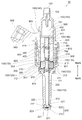
第2実施形態について、図2を参照しながら説明する。以下では、第1実施形態と異なる点について主に説明し、第1実施形態と共通する点については適宜説明を省略する。
The second embodiment will be described with reference to FIG. Hereinafter, differences from the first embodiment will be mainly described, and description of points that are common to the first embodiment will be omitted as appropriate.
本実施形態に係る燃料噴射弁10では、固定側高硬度部410のうち開弁側の部分に形成された拡径部411の先端が、第4筒状部材140の内面に当接しており、溶接により固定されている。一方、本実施形態では、固定側低硬度部420の外側面と、第4筒状部材140の内面との間が僅かに離間しており、両者は溶接されていない。
In the fuel injection valve 10 according to the present embodiment, the tip of the enlarged diameter portion 411 formed at the valve opening side portion of the fixed high hardness portion 410 is in contact with the inner surface of the fourth cylindrical member 140, It is fixed by welding. On the other hand, in the present embodiment, the outer surface of the fixed-side low hardness portion 420 and the inner surface of the fourth cylindrical member 140 are slightly separated from each other, and both are not welded.
このように、本実施形態では、固定側高硬度部410の拡径部411がハウジングの内面に接合されている。このような構成においては、開弁時において可動コア300が固定コア400に当たった際の衝撃が、固定側高硬度部410のみに対して直接的に加えられ、固定側低硬度部420には加えられない。このため、硬度の低い固定側低硬度部420の破損を更に防止することができる。
Thus, in this embodiment, the enlarged diameter portion 411 of the fixed-side high hardness portion 410 is joined to the inner surface of the housing. In such a configuration, the impact when the movable core 300 hits the fixed core 400 when the valve is opened is directly applied only to the fixed-side high hardness portion 410, and the fixed-side low hardness portion 420 has Cannot be added. For this reason, it is possible to further prevent the fixed-side low hardness portion 420 having a low hardness from being damaged.
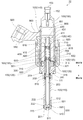
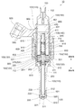
第3実施形態について、図3を参照しながら説明する。以下では、第1実施形態と異なる点について主に説明し、第1実施形態と共通する点については適宜説明を省略する。
The third embodiment will be described with reference to FIG. Hereinafter, differences from the first embodiment will be mainly described, and description of points that are common to the first embodiment will be omitted as appropriate.
本実施形態に係る燃料噴射弁10では、可動側高硬度部310に拡径部311が設けられていない。可動側高硬度部310は、その全体が円筒形状に形成されており、その閉弁側の端部が、可動側低硬度部320の閉弁側端部よりも更に閉弁側に伸びている。可動側高硬度部310のうち、可動側低硬度部320の閉弁側端部よりも更に閉弁側に伸びている部分のことを、以下では「延長部315」とも称する。延長部315は、第1筒状部材110の空間111の内側まで伸びている。延長部315の閉弁側端部の位置は、貫通穴202よりも僅かに開弁側となる位置である。延長部315の閉弁側端部は、スプリング810の端部に当接している。
In the fuel injection valve 10 according to the present embodiment, the movable side high hardness portion 310 is not provided with the enlarged diameter portion 311. The movable high hardness part 310 is entirely formed in a cylindrical shape, and the end on the valve closing side extends further to the valve closing side than the valve closing side end of the movable low hardness part 320. . A portion of the movable high hardness portion 310 that extends further to the valve closing side than the valve closing end of the movable low hardness portion 320 is also referred to as an “extension portion 315” below. The extension part 315 extends to the inside of the space 111 of the first tubular member 110. The position of the end portion on the valve closing side of the extension portion 315 is a position slightly on the valve opening side with respect to the through hole 202. The valve closing side end of the extension 315 is in contact with the end of the spring 810.
延長部315の外側面316は、第1筒状部材110のうち、空間111を区画する内面に当接した状態で摺動可能となっている。外側面316には、第1実施形態における先端面312と同様に、窒化処理及びDLCコートが施されている。また、これと対向する第1筒状部材110の内面には、窒化処理が施されている。
The outer side surface 316 of the extension part 315 is slidable in a state of being in contact with the inner surface of the first tubular member 110 that defines the space 111. The outer side surface 316 is subjected to nitriding and DLC coating in the same manner as the front end surface 312 in the first embodiment. Further, the inner surface of the first cylindrical member 110 facing this is subjected to nitriding treatment.
このような態様においては、可動コア300のうち摺動を案内される部分、すなわち延長部315の上下方向における長さが、先端面312(第1実施形態)の上下方向における長さに比べて長くなっている。このため、開弁時及び閉弁時における可動コア300の動きをより安定させることが可能となっている。
In such an aspect, the length of the movable core 300 that is guided to slide, that is, the length of the extension 315 in the vertical direction is larger than the length of the tip surface 312 (first embodiment) in the vertical direction. It is getting longer. For this reason, it is possible to further stabilize the movement of the movable core 300 at the time of valve opening and valve closing.
尚、本実施形態の第1筒状部材110には、可動コア300を外周から囲むような拡径円筒部112が形成されていない。代わりに、第2筒状部材120が下方側まで延長されている。これは、可動側高硬度部310の拡径部311が当接し摺動する部分(つまり拡径円筒部112)を、本実施形態では第2筒状部材120の近傍に設ける必要が無いからである。このような構成においては、第2筒状部材120が延長されることにより、当該部分における磁気抵抗が小さくなっている。その結果、固定コア400と可動コア300との間に発生する磁気吸引力が大きくなっており、燃料噴射弁の開弁動作がより効率的に行われる。
Note that the first cylindrical member 110 of the present embodiment is not formed with the enlarged cylindrical portion 112 that surrounds the movable core 300 from the outer periphery. Instead, the second cylindrical member 120 is extended to the lower side. This is because there is no need to provide a portion (that is, the enlarged diameter cylindrical portion 112) in which the enlarged diameter portion 311 of the movable high hardness portion 310 contacts and slides in the vicinity of the second cylindrical member 120 in this embodiment. is there. In such a configuration, when the second cylindrical member 120 is extended, the magnetic resistance in the portion is reduced. As a result, the magnetic attractive force generated between the fixed core 400 and the movable core 300 is increased, and the fuel injection valve is opened more efficiently.
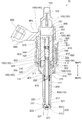
第4実施形態について、図4を参照しながら説明する。以下では、第1実施形態と異なる点について主に説明し、第1実施形態と共通する点については適宜説明を省略する。
The fourth embodiment will be described with reference to FIG. Hereinafter, differences from the first embodiment will be mainly described, and description of points that are common to the first embodiment will be omitted as appropriate.
本実施形態に係る燃料噴射弁10では、第1実施形態と同様の可動側高硬度部310に対し、第3実施形態(図3)と同様の延長部315を形成した構成となっている。つまり、本実施形態に係る可動側高硬度部310は、拡径部311の先端面312と、延長部315の外側面316と、の2箇所において第1筒状部材110に当接し摺動する。
The fuel injection valve 10 according to this embodiment has a configuration in which an extension 315 similar to that of the third embodiment (FIG. 3) is formed on the movable high hardness portion 310 similar to that of the first embodiment. That is, the movable high-hardness portion 310 according to the present embodiment slides in contact with the first tubular member 110 at two locations, that is, the tip surface 312 of the enlarged diameter portion 311 and the outer surface 316 of the extension portion 315. .
拡径部311よりも閉弁側となる位置には、拡径部311と第1筒状部材110とによって挟まれた空間であるダンパー室303が形成されている。また、可動コア300と固定コア400との間には、空間304が形成されている。ダンパー室303及び空間304は、いずれも燃料で満たされた状態となっている。ダンパー室303と空間304との間は、可動コア300を貫く貫通穴によって連通されている。本実施形態の貫通穴301にはオリフィス302が設けられており、貫通穴301における燃料の流路断面積が絞られている。
A damper chamber 303 that is a space sandwiched between the enlarged diameter portion 311 and the first tubular member 110 is formed at a position closer to the valve closing side than the enlarged diameter portion 311. A space 304 is formed between the movable core 300 and the fixed core 400. The damper chamber 303 and the space 304 are both filled with fuel. The damper chamber 303 and the space 304 are communicated with each other through a through hole that penetrates the movable core 300. An orifice 302 is provided in the through hole 301 of the present embodiment, and the flow passage cross-sectional area of the fuel in the through hole 301 is reduced.
固定側低硬度部420の外周面には、上下方向に伸びるスリット状の溝、である連通路421が形成されている。連通路421により、閉弁側の空間304と、開弁側の空間151とが連通されている。このため、可動コア300の動作状態や位置に拘らず、空間304における燃料の圧力は概ね一定となっている。
A communication path 421 that is a slit-like groove extending in the vertical direction is formed on the outer peripheral surface of the fixed-side low hardness portion 420. The valve-closing space 304 and the valve-opening space 151 communicate with each other through the communication passage 421. For this reason, the fuel pressure in the space 304 is substantially constant regardless of the operating state and position of the movable core 300.
コイル600への電流共有が開始され、可動コア300が開弁側に移動すると、空間304に存在していた燃料は、貫通穴301及びオリフィス302を通ってダンパー室303に移動する。可動コア300の移動速度が大きくなると、上記のような燃料の移動はオリフィス302によって抑制される。このため、可動コア300が開弁側端部に到達した際の、可動側高硬度部310と固定側高硬度部410との衝突エネルギーを低く抑えることができる。
When current sharing to the coil 600 is started and the movable core 300 moves to the valve opening side, the fuel existing in the space 304 moves to the damper chamber 303 through the through hole 301 and the orifice 302. When the moving speed of the movable core 300 increases, the movement of the fuel as described above is suppressed by the orifice 302. For this reason, when the movable core 300 reaches the valve opening side end, the collision energy between the movable high hardness portion 310 and the fixed high hardness portion 410 can be kept low.
コイル600への電流共有が停止され、可動コア300が閉弁側に移動すると、ダンパー室303に存在していた燃料は、貫通穴301及びオリフィス302を通って空間304に移動する。可動コア300の移動速度が大きくなると、上記のような燃料の移動はオリフィス302によって抑制される。このため、可動コア300が閉弁側端部に到達した際の、シール部221と弁座512との衝突エネルギーを低く抑えることができる。
When the current sharing to the coil 600 is stopped and the movable core 300 moves to the valve closing side, the fuel existing in the damper chamber 303 moves to the space 304 through the through hole 301 and the orifice 302. When the moving speed of the movable core 300 increases, the movement of the fuel as described above is suppressed by the orifice 302. For this reason, when the movable core 300 reaches | attains the valve closing side edge part, the collision energy of the seal part 221 and the valve seat 512 can be suppressed low.
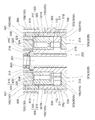
第5実施形態について、図5及び図6を参照しながら説明する。以下では、上記の第4実施形態(図4)と異なる点について主に説明し、第4実施形態と共通する点については適宜説明を省略する。
The fifth embodiment will be described with reference to FIGS. Hereinafter, differences from the above-described fourth embodiment (FIG. 4) will be mainly described, and description of points common to the fourth embodiment will be omitted as appropriate.
本実施形態では、一部の貫通穴301には第4実施形態のオリフィス302が設けられている一方で、他の一部の貫通穴301には弁306が設けられている。オリフィス302が設けられている方の貫通穴301のことを、以下では「貫通穴301A」とも表記する。また、弁306が設けられている方の貫通穴301のことを、以下では「貫通穴301B」とも表記する。
In this embodiment, some through holes 301 are provided with the orifices 302 of the fourth embodiment, while other partial through holes 301 are provided with valves 306. The through hole 301 provided with the orifice 302 is hereinafter also referred to as “through hole 301A”. Further, the through hole 301 on which the valve 306 is provided is also referred to as “through hole 301B” below.
弁306は、貫通穴301Bにおける燃料の流れや圧力に応じて上下方向に移動可能となっている。弁306によって、貫通穴301Bを開弁方向に向かうような燃料の流れは禁止される一方で、貫通穴301Bを閉弁方向に向かうような燃料の流れは許容される。つまり、弁306は所謂「逆止弁」として機能するものである。
The valve 306 is movable in the vertical direction according to the fuel flow and pressure in the through hole 301B. While the valve 306 prohibits the flow of fuel that goes through the through hole 301B in the valve opening direction, the flow of fuel that passes through the through hole 301B in the valve closing direction is allowed. That is, the valve 306 functions as a so-called “check valve”.
コイル600への電流共有が開始され、可動コア300が開弁側に移動すると、空間304に存在していた燃料は、その一部が貫通穴301A及びオリフィス302を通ってダンパー室303に移動する。また、空間304に存在していた燃料の残部(実際には大部分である)は、貫通穴301Bを通ってダンパー室303に移動する。このため、開弁時においては、オリフィス302が設けられていることによる可動コア300の減速効果はほとんど得られない。
When current sharing to the coil 600 is started and the movable core 300 moves to the valve opening side, a part of the fuel existing in the space 304 moves to the damper chamber 303 through the through hole 301A and the orifice 302. . Further, the remaining portion (in fact, most of the fuel) present in the space 304 moves to the damper chamber 303 through the through hole 301B. For this reason, at the time of valve opening, the deceleration effect of the movable core 300 by providing the orifice 302 is hardly obtained.
コイル600への電流共有が停止され、可動コア300が閉弁側に移動すると、ダンパー室303に存在していた燃料は、貫通穴301A及びオリフィス302を通って空間304に移動する。一方、貫通穴301Bを通って空間304に向かうような燃料の流れは、弁306によって妨げられる。このため、閉弁時においては、第4実施形態と同様に、可動コア300の移動速度がオリフィス302によって減速される。
When the current sharing to the coil 600 is stopped and the movable core 300 moves to the valve closing side, the fuel existing in the damper chamber 303 moves to the space 304 through the through hole 301A and the orifice 302. On the other hand, the flow of fuel that goes to the space 304 through the through hole 301 </ b> B is blocked by the valve 306. For this reason, when the valve is closed, the moving speed of the movable core 300 is reduced by the orifice 302 as in the fourth embodiment.
このように本実施形態では、開弁時においては迅速に可動コア300及びニードル200が開弁方向に移動する一方で、閉弁時においては可動コア300及びニードル200の移動速度がオリフィス302によって減速される。可動側高硬度部310と固定側高硬度部410との衝突エネルギーを低く抑えることよりも、シール部221と弁座512との衝突エネルギーを低く抑えることの方をより重視する場合には、このような構成とすることが好ましい。
Thus, in this embodiment, the movable core 300 and the needle 200 move quickly in the valve opening direction when the valve is opened, while the moving speed of the movable core 300 and the needle 200 is reduced by the orifice 302 when the valve is closed. Is done. In the case where it is more important to keep the collision energy between the seal part 221 and the valve seat 512 lower than to keep the collision energy between the movable side high hardness part 310 and the fixed side high hardness part 410 low, this Such a configuration is preferable.
図6に拡大して示されるように、可動側低硬度部320のうち開弁側の端面では、貫通穴301A、301Bの周囲の部分が、他の部分よりも開弁側に向けて突出している。この突出している部分のことを、以下では「土手部325」とも称する。可動コア300及びニードル200が開弁側端部に位置している状態、すなわちフルリフト状態において、可動コア300と固定コア400との間の隙間の大きさは、土手部325においては10μm程度となっており、その周囲においては50μm程度となるように設定されている。
As shown in an enlarged view in FIG. 6, in the end surface on the valve opening side of the movable-side low-hardness portion 320, the portions around the through holes 301 </ b> A and 301 </ b> B protrude toward the valve opening side from the other portions. Yes. This protruding portion is also referred to as “bank portion 325” below. In a state where the movable core 300 and the needle 200 are located at the valve opening side end, that is, in a full lift state, the size of the gap between the movable core 300 and the fixed core 400 is about 10 μm at the bank portion 325. It is set to be about 50 μm around it.
コイル600への電流共有が開始され、可動コア300が開弁側に移動すると、土手部325と固定コア400との間の距離は次第に小さくなって行く。当該距離が50μmよりも小さくなると、両者の隙間を流れる燃料に働く流路抵抗が急速に増大し、空間304から貫通穴301A、301Bに流入する燃料の流れが妨げられる。その結果、開弁が完了する直前において可動コア300の移動速度が低減されるので、可動側高硬度部310と固定側高硬度部410との衝突エネルギーを低く抑えることができる。
When current sharing to the coil 600 is started and the movable core 300 moves to the valve opening side, the distance between the bank portion 325 and the fixed core 400 gradually decreases. When the distance is smaller than 50 μm, the flow resistance acting on the fuel flowing through the gap between the two rapidly increases, and the flow of fuel flowing from the space 304 into the through holes 301A and 301B is hindered. As a result, since the moving speed of the movable core 300 is reduced immediately before the valve opening is completed, the collision energy between the movable high hardness part 310 and the fixed high hardness part 410 can be kept low.
また、図6に拡大して示されるように、拡径部311のうち閉弁側の端面では、貫通穴301A、301Bの全体を外側から囲むような円環状の部分が、閉弁側に向けて突出している。この突出している部分のことを、以下では「土手部318」とも称する。また、ダンパー室303のうち、土手部318よりも外側の空間のことを、以下では「外側ダンパー室303A」とも称する。更に、土手部318よりも内側の空間のことを、以下では「内側ダンパー室303B」とも称する。
Further, as shown in an enlarged view in FIG. 6, an annular portion that surrounds the entire through holes 301 </ b> A and 301 </ b> B from the outside on the end face on the valve closing side of the enlarged diameter portion 311 faces the valve closing side. Protruding. This protruding portion is also referred to as “bank portion 318” below. In the damper chamber 303, a space outside the bank portion 318 is also referred to as an “outer damper chamber 303A” below. Furthermore, the space inside the bank portion 318 is hereinafter also referred to as “inner damper chamber 303B”.
コイル600への電流共有が停止され、可動コア300及びニードル200が閉弁側に移動すると、土手部325と第1筒状部材110との間の距離は次第に小さくなって行く。当該距離が50μmよりも小さくなると、両者の隙間を流れる燃料に働く流路抵抗が急速に増大し、外側ダンパー室303Aから内側ダンパー室303Bに流入する燃料の流れが妨げられる。その結果、ニードル200による閉弁が完了した後、可動コア300が下方への移動を継続し第1筒状部材110に衝突する際、可動コア300の移動速度が低減されるので、可動コア300と第1筒部材110との衝突エネルギーを低く抑えることができる。
When the current sharing to the coil 600 is stopped and the movable core 300 and the needle 200 move to the valve closing side, the distance between the bank portion 325 and the first tubular member 110 gradually decreases. When the distance is less than 50 μm, the flow resistance acting on the fuel flowing through the gap between the two rapidly increases, and the flow of fuel flowing from the outer damper chamber 303A into the inner damper chamber 303B is hindered. As a result, after the valve closing by the needle 200 is completed, when the movable core 300 continues to move downward and collides with the first cylindrical member 110, the moving speed of the movable core 300 is reduced. And the first cylinder member 110 can be kept low in collision energy.
第6実施形態について、図7を参照しながら説明する。以下では、第1実施形態と異なる点について主に説明し、第1実施形態と共通する点については適宜説明を省略する。
The sixth embodiment will be described with reference to FIG. Hereinafter, differences from the first embodiment will be mainly described, and description of points that are common to the first embodiment will be omitted as appropriate.
本実施形態では、可動コア300の可動側高硬度部310と、ニードル200の上方側部分とが一体となっている。ニードル200のうち固定側低硬度部420に当たる部分には、本実施形態でも窒化処理が施されている。また、ニードル200のうち第1筒状部材110の拡径円筒部112に当接し摺動する部分(つまり、拡径部311の先端面312)には、本実施形態でも窒化処理及びDLCコートが施されている。このような態様であっても、第1実施形態において説明したものと同様の効果を奏する。
In the present embodiment, the movable side high hardness portion 310 of the movable core 300 and the upper side portion of the needle 200 are integrated. The portion of the needle 200 that corresponds to the fixed-side low hardness portion 420 is also subjected to nitriding treatment in this embodiment. Further, in this embodiment, the nitriding treatment and the DLC coat are also applied to the portion of the needle 200 that contacts and slides on the enlarged cylindrical portion 112 of the first cylindrical member 110 (that is, the distal end surface 312 of the enlarged diameter portion 311). It has been subjected. Even if it is such an aspect, there exists an effect similar to what was demonstrated in 1st Embodiment.
以上、具体例を参照しつつ本実施形態について説明した。しかし、本開示はこれらの具体例に限定されるものではない。これら具体例に、当業者が適宜設計変更を加えたものも、本開示の特徴を備えている限り、本開示の範囲に包含される。前述した各具体例が備える各要素およびその配置、条件、形状などは、例示したものに限定されるわけではなく適宜変更することができる。前述した各具体例が備える各要素は、技術的な矛盾が生じない限り、適宜組み合わせを変えることができる。
The embodiment has been described above with reference to specific examples. However, the present disclosure is not limited to these specific examples. Those in which those skilled in the art appropriately modify the design of these specific examples are also included in the scope of the present disclosure as long as they have the features of the present disclosure. Each element included in each of the specific examples described above and their arrangement, conditions, shape, and the like are not limited to those illustrated, and can be changed as appropriate. Each element included in each of the specific examples described above can be appropriately combined as long as no technical contradiction occurs.
Claims (9)
- 燃料を噴射するための噴孔(511)が、長手方向における一端に形成されたハウジング(100)と、
前記ハウジングの内部において前記長手方向に沿って移動することにより、前記噴孔の開閉を切り換えるニードル(200)と、
少なくとも一部が磁性体によって形成された部材であって、前記ハウジングの内部に固定されている固定コア(400)と、
少なくとも一部が磁性体によって形成された部材であって、前記ハウジングの内部において、前記長手方向に沿って前記ニードルと共に移動可能な状態で配置されている可動コア(300)と、
前記固定コアと前記可動コアとの間に磁気吸引力を発生させるコイル(600)と、を備え、
前記固定コアは、硬度が高い固定側高硬度部(410)と、前記固定側高硬度部よりも硬度が低い固定側低硬度部(420)と、を有しており、
前記可動コアは、硬度が高い可動側高硬度部(310)と、前記可動側高硬度部よりも硬度が低い可動側低硬度部(320)と、を有しており、
前記コイルに電流が供給されると、発生した前記磁気吸引力によって前記可動コアが前記ニードルと共に前記固定コア側に移動し、前記可動側高硬度部が前記固定側高硬度部に当たるように構成されている燃料噴射弁。 A housing (100) having an injection hole (511) for injecting fuel formed at one end in the longitudinal direction;
A needle (200) that switches between opening and closing of the nozzle hole by moving along the longitudinal direction inside the housing;
A fixed core (400) which is a member at least partially formed of a magnetic material and is fixed inside the housing;
A movable core (300) that is a member at least partially formed of a magnetic material, and is arranged inside the housing so as to be movable with the needle along the longitudinal direction;
A coil (600) for generating a magnetic attractive force between the fixed core and the movable core,
The fixed core includes a fixed-side high hardness portion (410) having a high hardness and a fixed-side low hardness portion (420) having a hardness lower than that of the fixed-side high hardness portion,
The movable core has a movable high hardness part (310) having a high hardness and a movable low hardness part (320) having a hardness lower than that of the movable high hardness part,
When a current is supplied to the coil, the movable core moves to the fixed core side together with the needle by the generated magnetic attraction force, and the movable side high hardness portion hits the fixed side high hardness portion. Fuel injection valve. - 前記固定側高硬度部は、前記固定コアのうち前記長手方向に沿った一方側の端部から他方側の端部まで伸びるように形成されており、
前記可動側高硬度部は、前記可動コアのうち前記長手方向に沿った一方側の端部から他方側の端部まで伸びるように形成されている、請求項1に記載の燃料噴射弁。 The fixed-side high hardness portion is formed so as to extend from one end portion along the longitudinal direction of the fixed core to the other end portion,
2. The fuel injection valve according to claim 1, wherein the movable-side high-hardness portion is formed so as to extend from one end portion along the longitudinal direction of the movable core to the other end portion. - 前記固定側高硬度部が前記ハウジングの内面に接合されている、請求項2に記載の燃料噴射弁。 The fuel injection valve according to claim 2, wherein the fixed high hardness portion is joined to the inner surface of the housing.
- 前記固定側高硬度部は、少なくともその一部が前記固定側低硬度部よりも内側となる位置に配置されており、
前記可動側高硬度部は、少なくともその一部が前記可動側低硬度部よりも内側となる位置に配置されている、請求項2に記載の燃料噴射弁。 The fixed-side high hardness part is arranged at a position where at least a part thereof is inside the fixed-side low hardness part,
3. The fuel injection valve according to claim 2, wherein at least a part of the movable-side high hardness portion is disposed at a position inside the movable-side low hardness portion. - 前記可動コアには、前記可動側高硬度部を前記長手方向に沿って貫く可動側貫通穴(313)が形成されており、
前記ニードルは前記可動側貫通穴に挿通されている、請求項4に記載の燃料噴射弁。 The movable core is formed with a movable side through hole (313) penetrating the movable side high hardness portion along the longitudinal direction.
The fuel injection valve according to claim 4, wherein the needle is inserted through the movable side through hole. - 前記可動側高硬度部が、前記ハウジングの内面に当接した状態で摺動するように構成されている、請求項1に記載の燃料噴射弁。 2. The fuel injection valve according to claim 1, wherein the movable-side high-hardness portion is configured to slide while being in contact with the inner surface of the housing.
- 前記可動側高硬度部と前記ニードルとが一体となっている、請求項1に記載の燃料噴射弁。 The fuel injection valve according to claim 1, wherein the movable-side high-hardness portion and the needle are integrated.
- 前記可動コア及び前記ニードルの移動に伴って、互いに当接した状態で摺動する部分である第1部分と第2部分のうち少なくとも一方に、その硬度を高めるための高硬度化処理が施されている、請求項1乃至7のいずれか1項に記載の燃料噴射弁。 In accordance with the movement of the movable core and the needle, at least one of the first part and the second part, which are parts that slide in contact with each other, is subjected to a hardening process for increasing its hardness. The fuel injection valve according to any one of claims 1 to 7.
- 前記可動コア及び前記ニードルの移動に伴って、互いに当接した状態で摺動する部分である第1部分と第2部分のうち少なくとも一方に、摩擦力を低下させるための表面処理が施されている、請求項1乃至8のいずれか1項に記載の燃料噴射弁。 In accordance with the movement of the movable core and the needle, at least one of the first part and the second part, which are parts that slide in contact with each other, is subjected to a surface treatment for reducing the frictional force. The fuel injection valve according to any one of claims 1 to 8.
Priority Applications (2)
| Application Number | Priority Date | Filing Date | Title |
|---|---|---|---|
| DE112018002252.8T DE112018002252T5 (en) | 2017-04-28 | 2018-03-16 | Fuel injection valve |
| US16/665,579 US20210108603A1 (en) | 2017-04-28 | 2019-10-28 | Fuel injection valve |
Applications Claiming Priority (2)
| Application Number | Priority Date | Filing Date | Title |
|---|---|---|---|
| JP2017-090295 | 2017-04-28 | ||
| JP2017090295A JP6836955B2 (en) | 2017-04-28 | 2017-04-28 | Fuel injection valve |
Related Child Applications (1)
| Application Number | Title | Priority Date | Filing Date |
|---|---|---|---|
| US16/665,579 Continuation US20210108603A1 (en) | 2017-04-28 | 2019-10-28 | Fuel injection valve |
Publications (1)
| Publication Number | Publication Date |
|---|---|
| WO2018198592A1 true WO2018198592A1 (en) | 2018-11-01 |
Family
ID=63918913
Family Applications (1)
| Application Number | Title | Priority Date | Filing Date |
|---|---|---|---|
| PCT/JP2018/010587 WO2018198592A1 (en) | 2017-04-28 | 2018-03-16 | Fuel injection valve |
Country Status (4)
| Country | Link |
|---|---|
| US (1) | US20210108603A1 (en) |
| JP (1) | JP6836955B2 (en) |
| DE (1) | DE112018002252T5 (en) |
| WO (1) | WO2018198592A1 (en) |
Cited By (1)
| Publication number | Priority date | Publication date | Assignee | Title |
|---|---|---|---|---|
| CN113167200A (en) * | 2019-01-28 | 2021-07-23 | 株式会社电装 | Fuel injection device |
Families Citing this family (3)
| Publication number | Priority date | Publication date | Assignee | Title |
|---|---|---|---|---|
| JP7352384B2 (en) | 2019-06-06 | 2023-09-28 | 株式会社Soken | fuel injection valve |
| JP7268546B2 (en) * | 2019-09-03 | 2023-05-08 | 株式会社デンソー | injector |
| JP7376366B2 (en) | 2020-01-07 | 2023-11-08 | 株式会社Soken | Manufacturing method of fuel injection valve |
Citations (6)
| Publication number | Priority date | Publication date | Assignee | Title |
|---|---|---|---|---|
| JP2000170619A (en) * | 1998-12-09 | 2000-06-20 | Keihin Corp | Manufacture of core of electromagnetic fuel injection valve |
| JP2002349745A (en) * | 2001-05-25 | 2002-12-04 | Nippon Soken Inc | Solenoid valve |
| JP2004088891A (en) * | 2002-08-26 | 2004-03-18 | Nippon Soken Inc | Electromagnetic actuator |
| US20120153034A1 (en) * | 2010-12-20 | 2012-06-21 | Caterpillar Inc. | Solenoid Actuator And Fuel Injector Using Same |
| EP2719886A1 (en) * | 2012-10-10 | 2014-04-16 | Continental Automotive GmbH | Valve assembly for an injection valve |
| JP2017031963A (en) * | 2015-08-06 | 2017-02-09 | 株式会社デンソー | Fuel injection device |
Family Cites Families (2)
| Publication number | Priority date | Publication date | Assignee | Title |
|---|---|---|---|---|
| JP5862941B2 (en) | 2011-11-08 | 2016-02-16 | 株式会社デンソー | Fuel injection valve |
| JP2017090295A (en) | 2015-11-12 | 2017-05-25 | 株式会社イシダ | Combined quantity measuring device |
-
2017
- 2017-04-28 JP JP2017090295A patent/JP6836955B2/en active Active
-
2018
- 2018-03-16 WO PCT/JP2018/010587 patent/WO2018198592A1/en active Application Filing
- 2018-03-16 DE DE112018002252.8T patent/DE112018002252T5/en active Pending
-
2019
- 2019-10-28 US US16/665,579 patent/US20210108603A1/en not_active Abandoned
Patent Citations (6)
| Publication number | Priority date | Publication date | Assignee | Title |
|---|---|---|---|---|
| JP2000170619A (en) * | 1998-12-09 | 2000-06-20 | Keihin Corp | Manufacture of core of electromagnetic fuel injection valve |
| JP2002349745A (en) * | 2001-05-25 | 2002-12-04 | Nippon Soken Inc | Solenoid valve |
| JP2004088891A (en) * | 2002-08-26 | 2004-03-18 | Nippon Soken Inc | Electromagnetic actuator |
| US20120153034A1 (en) * | 2010-12-20 | 2012-06-21 | Caterpillar Inc. | Solenoid Actuator And Fuel Injector Using Same |
| EP2719886A1 (en) * | 2012-10-10 | 2014-04-16 | Continental Automotive GmbH | Valve assembly for an injection valve |
| JP2017031963A (en) * | 2015-08-06 | 2017-02-09 | 株式会社デンソー | Fuel injection device |
Cited By (2)
| Publication number | Priority date | Publication date | Assignee | Title |
|---|---|---|---|---|
| CN113167200A (en) * | 2019-01-28 | 2021-07-23 | 株式会社电装 | Fuel injection device |
| CN113167200B (en) * | 2019-01-28 | 2022-08-02 | 株式会社电装 | Fuel injection device |
Also Published As
| Publication number | Publication date |
|---|---|
| JP6836955B2 (en) | 2021-03-03 |
| DE112018002252T5 (en) | 2020-01-16 |
| JP2018189002A (en) | 2018-11-29 |
| US20210108603A1 (en) | 2021-04-15 |
Similar Documents
| Publication | Publication Date | Title |
|---|---|---|
| WO2018198592A1 (en) | Fuel injection valve | |
| WO2016163110A1 (en) | Fuel injection valve | |
| US20170254304A1 (en) | Fuel injection valve | |
| WO2017022163A1 (en) | Fuel injection device | |
| JP2016061200A (en) | Fuel injection valve | |
| JP6544416B2 (en) | Fuel injection valve | |
| JP7311315B2 (en) | fuel injector | |
| WO2020246385A1 (en) | Fuel injection valve | |
| JP7116609B2 (en) | fuel injector | |
| EP3156638B1 (en) | Fuel injector | |
| JP7063741B2 (en) | Fuel injection valve | |
| JP6160562B2 (en) | Fuel injection valve | |
| CN111344483B (en) | Fuel injection device | |
| JP7323445B2 (en) | fuel injector | |
| JP6733701B2 (en) | Injector | |
| JP7284063B2 (en) | fuel injector | |
| JP7323444B2 (en) | fuel injector | |
| US10718302B2 (en) | Fuel injection device | |
| WO2019017097A1 (en) | Fuel injection valve | |
| JP7376337B2 (en) | fuel injection valve | |
| JP2019203406A (en) | Fuel injection valve | |
| JP2015218664A (en) | Fuel injection valve | |
| JP7197383B2 (en) | fuel injector | |
| JP2012225185A (en) | Fuel injection valve | |
| WO2018230081A1 (en) | Fuel injection valve |
Legal Events
| Date | Code | Title | Description |
|---|---|---|---|
| 121 | Ep: the epo has been informed by wipo that ep was designated in this application |
Ref document number: 18789879 Country of ref document: EP Kind code of ref document: A1 |
|
| 122 | Ep: pct application non-entry in european phase |
Ref document number: 18789879 Country of ref document: EP Kind code of ref document: A1 |