WO2020246385A1 - Fuel injection valve - Google Patents
Fuel injection valve Download PDFInfo
- Publication number
- WO2020246385A1 WO2020246385A1 PCT/JP2020/021340 JP2020021340W WO2020246385A1 WO 2020246385 A1 WO2020246385 A1 WO 2020246385A1 JP 2020021340 W JP2020021340 W JP 2020021340W WO 2020246385 A1 WO2020246385 A1 WO 2020246385A1
- Authority
- WO
- WIPO (PCT)
- Prior art keywords
- needle
- fuel
- housing
- movable
- fixed
- Prior art date
Links
Images


Classifications
-
- F—MECHANICAL ENGINEERING; LIGHTING; HEATING; WEAPONS; BLASTING
- F02—COMBUSTION ENGINES; HOT-GAS OR COMBUSTION-PRODUCT ENGINE PLANTS
- F02M—SUPPLYING COMBUSTION ENGINES IN GENERAL WITH COMBUSTIBLE MIXTURES OR CONSTITUENTS THEREOF
- F02M21/00—Apparatus for supplying engines with non-liquid fuels, e.g. gaseous fuels stored in liquid form
- F02M21/02—Apparatus for supplying engines with non-liquid fuels, e.g. gaseous fuels stored in liquid form for gaseous fuels
- F02M21/0203—Apparatus for supplying engines with non-liquid fuels, e.g. gaseous fuels stored in liquid form for gaseous fuels characterised by the type of gaseous fuel
- F02M21/0206—Non-hydrocarbon fuels, e.g. hydrogen, ammonia or carbon monoxide
-
- F—MECHANICAL ENGINEERING; LIGHTING; HEATING; WEAPONS; BLASTING
- F02—COMBUSTION ENGINES; HOT-GAS OR COMBUSTION-PRODUCT ENGINE PLANTS
- F02M—SUPPLYING COMBUSTION ENGINES IN GENERAL WITH COMBUSTIBLE MIXTURES OR CONSTITUENTS THEREOF
- F02M21/00—Apparatus for supplying engines with non-liquid fuels, e.g. gaseous fuels stored in liquid form
- F02M21/02—Apparatus for supplying engines with non-liquid fuels, e.g. gaseous fuels stored in liquid form for gaseous fuels
- F02M21/0218—Details on the gaseous fuel supply system, e.g. tanks, valves, pipes, pumps, rails, injectors or mixers
- F02M21/0248—Injectors
- F02M21/0251—Details of actuators therefor
- F02M21/0254—Electric actuators, e.g. solenoid or piezoelectric
-
- F—MECHANICAL ENGINEERING; LIGHTING; HEATING; WEAPONS; BLASTING
- F02—COMBUSTION ENGINES; HOT-GAS OR COMBUSTION-PRODUCT ENGINE PLANTS
- F02M—SUPPLYING COMBUSTION ENGINES IN GENERAL WITH COMBUSTIBLE MIXTURES OR CONSTITUENTS THEREOF
- F02M21/00—Apparatus for supplying engines with non-liquid fuels, e.g. gaseous fuels stored in liquid form
- F02M21/02—Apparatus for supplying engines with non-liquid fuels, e.g. gaseous fuels stored in liquid form for gaseous fuels
- F02M21/0218—Details on the gaseous fuel supply system, e.g. tanks, valves, pipes, pumps, rails, injectors or mixers
- F02M21/0248—Injectors
- F02M21/0257—Details of the valve closing elements, e.g. valve seats, stems or arrangement of flow passages
- F02M21/026—Lift valves, i.e. stem operated valves
- F02M21/0263—Inwardly opening single or multi nozzle valves, e.g. needle valves
- F02M21/0266—Hollow stem valves; Piston valves; Stems having a spherical tip
-
- F—MECHANICAL ENGINEERING; LIGHTING; HEATING; WEAPONS; BLASTING
- F02—COMBUSTION ENGINES; HOT-GAS OR COMBUSTION-PRODUCT ENGINE PLANTS
- F02M—SUPPLYING COMBUSTION ENGINES IN GENERAL WITH COMBUSTIBLE MIXTURES OR CONSTITUENTS THEREOF
- F02M51/00—Fuel-injection apparatus characterised by being operated electrically
- F02M51/06—Injectors peculiar thereto with means directly operating the valve needle
- F02M51/061—Injectors peculiar thereto with means directly operating the valve needle using electromagnetic operating means
-
- F—MECHANICAL ENGINEERING; LIGHTING; HEATING; WEAPONS; BLASTING
- F02—COMBUSTION ENGINES; HOT-GAS OR COMBUSTION-PRODUCT ENGINE PLANTS
- F02M—SUPPLYING COMBUSTION ENGINES IN GENERAL WITH COMBUSTIBLE MIXTURES OR CONSTITUENTS THEREOF
- F02M2200/00—Details of fuel-injection apparatus, not otherwise provided for
- F02M2200/30—Fuel-injection apparatus having mechanical parts, the movement of which is damped
- F02M2200/304—Fuel-injection apparatus having mechanical parts, the movement of which is damped using hydraulic means
-
- Y—GENERAL TAGGING OF NEW TECHNOLOGICAL DEVELOPMENTS; GENERAL TAGGING OF CROSS-SECTIONAL TECHNOLOGIES SPANNING OVER SEVERAL SECTIONS OF THE IPC; TECHNICAL SUBJECTS COVERED BY FORMER USPC CROSS-REFERENCE ART COLLECTIONS [XRACs] AND DIGESTS
- Y02—TECHNOLOGIES OR APPLICATIONS FOR MITIGATION OR ADAPTATION AGAINST CLIMATE CHANGE
- Y02T—CLIMATE CHANGE MITIGATION TECHNOLOGIES RELATED TO TRANSPORTATION
- Y02T10/00—Road transport of goods or passengers
- Y02T10/10—Internal combustion engine [ICE] based vehicles
- Y02T10/30—Use of alternative fuels, e.g. biofuels
Definitions
- This disclosure relates to a fuel injection valve.
- a fuel injection valve As a fuel injection valve provided in an internal combustion engine, a fuel injection valve having a configuration in which an internal movable core is operated together with a needle by a magnetic attraction force to switch the opening and closing of a fuel injection hole, which is a fuel outlet, is known.
- the fuel injection valve described in Patent Document 1 below has a fixed core fixed inside a housing, a movable core arranged in a movable state inside the housing, and magnetism between the fixed core and the movable core. It is equipped with a coil that generates suction force. When fuel is injected from the fuel injection valve, an electric current is supplied to the coil. Due to the magnetic attraction generated at that time, the movable core moves to the fixed core side together with the needle, and the injection hole is opened.
- Patent Document 1 also describes an example of a fuel injection valve in which a damper chamber for attenuating the operating speed of a movable core is formed inside a housing, specifically, at a position between the movable core and the housing. ing.
- a spring is often placed to urge the movable core toward the direction opposite to the injection hole. If the spring constant of the spring is not an appropriate value, resonance may occur inside the housing. In order to surely prevent resonance, it is preferable to secure a relatively large space for arranging the spring and increase the degree of freedom in designing the spring. Therefore, it is preferable that the spring is arranged in a portion of the inside of the housing that can secure a relatively wide space, specifically, a position between the movable core and the housing.
- An object of the present disclosure is to provide a fuel injection valve capable of fully exerting the damping effect of the damper chamber while ensuring a wide space for arranging the spring.
- the injection hole for injecting fuel switches between opening and closing of the injection hole by moving along the longitudinal direction with a housing formed at one end in the longitudinal direction and inside the housing.
- the needle at least a member formed of a magnetic material and fixed core fixed inside the housing, and at least a part of a member formed of a magnetic material inside the housing. It includes a movable core that is arranged so as to be movable with a needle along the longitudinal direction, and a coil that generates a magnetic attraction force between the fixed core and the movable core.
- a damper chamber is formed between the needle and the housing to reduce the operating speed of the needle.
- a damper chamber for attenuating the operating speed of the needle is formed at a position between the needle and the housing. Since it is not necessary to form a damper chamber at a position between the movable core and the housing, a wide space for arranging the spring can be secured at that position. As a result, it is possible to fully exert the damping effect of the damper chamber while securing a large space for arranging the spring.
- a fuel injection valve that can sufficiently exert the damping effect of the damper chamber while securing a large space for arranging the spring.
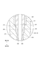
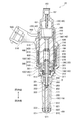
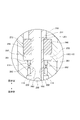
- FIG. 1 is a cross-sectional view showing the internal structure of the fuel injection valve according to the first embodiment.
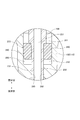
- FIG. 2 is an enlarged view showing the configuration of part A in FIG.
- FIG. 3 is a cross-sectional view showing the internal structure of the fuel injection valve according to the second embodiment.
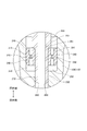
- FIG. 4 is an enlarged view showing the configuration of the portion B of FIG.
- FIG. 5 is a cross-sectional view showing a part of the internal structure of the fuel injection valve according to the third embodiment.
- FIG. 6 is a cross-sectional view showing a part of the internal structure of the fuel injection valve according to the fourth embodiment.
- FIG. 7 is a cross-sectional view showing a part of the internal structure of the fuel injection valve according to the fifth embodiment.
- the configuration of the fuel injection valve 10 according to the first embodiment will be described with reference to FIG.
- the fuel injection valve 10 is provided in an internal combustion engine (not shown) and is a device for injecting and supplying fuel to the internal combustion engine.
- As the fuel gaseous fuel, specifically hydrogen, is used in this embodiment.
- the fuel injection valve 10 includes a housing 100, a needle 200, a movable core 300, a fixed core 400, and a coil 600.
- the housing 100 is a member whose entire shape is formed as a substantially tubular container.
- FIG. 1 a state in which the housing 100 is oriented vertically along its longitudinal direction is depicted.
- the term "upper side” or the like may be used to indicate the upper side in FIG.
- a word such as “lower side” may be simply used to indicate the lower side in FIG.
- FIGS. 2 to 7 used in the following description.
- the fuel injected from the fuel injection valve 10 flows inside the housing 100 from the upper side to the lower side.
- the needle 200, the movable core 300, and the fixed core 400, which will be described later, are housed inside any of the housings 100.
- the housing 100 includes a first tubular member 110, a second tubular member 120, a third tubular member 130, a fourth tubular member 140, and a fifth tubular member 150. All of these are formed as substantially cylindrical members, and are arranged so that their central axes coincide with each other.
- the first tubular member 110 is a member of the housing 100 that is arranged at the most downstream position along the direction in which fuel flows.
- the first tubular member 110 is made of martensitic stainless steel and is subjected to a quenching treatment in order to increase its hardness.
- a space 111 is formed inside the first tubular member 110, and the needle 200 described later is housed in this space 111.
- the injection nozzle 500 is press-fitted inward and welded.
- the injection nozzle 500 forms a part of the housing 100, and has a cylindrical portion 520 and a closing portion 510.
- the cylindrical portion 520 is a portion formed in a cylindrical shape.
- the cylindrical portion 520 is fitted inside the first tubular member 110 with its central axis aligned with the central axis of the first tubular member 110.
- the inner peripheral surface 521 of the cylindrical portion 520 is a surface that slides in a state where the sliding contact portion 222 (described later) of the needle 200 is in contact with the inner peripheral surface 521.
- the closed portion 510 is a portion of the cylindrical portion 520 formed so as to close the lower end.
- a jet hole 511 is formed in the closed portion 510.
- the injection hole 511 is a through hole formed so as to penetrate the center of the closed portion 510 in the vertical direction of FIG.
- the injection hole 511 communicates the internal space 111 of the first tubular member 110 with the external space.
- the injection hole 511 is formed as an outlet for fuel injected from the fuel injection valve 10.
- a injection hole 511 for injecting fuel is formed at one end of the housing 100 in the longitudinal direction.
- a valve seat 512 is formed on the inner surface of the closed portion 510 so as to surround the periphery of the injection hole 511.
- the valve seat 512 is a portion that the seal portion 221 (described later) of the needle 200 abuts in order to close the injection hole 511.
- the entire injection nozzle 500 is made of martensitic stainless steel, and is subjected to quenching treatment in order to increase its hardness. Further, the portion of the injection nozzle 500 that the needle 200 abuts, that is, the valve seat 512 and the inner peripheral surface 521 is subjected to nitriding treatment. The inner peripheral surface 521 is further coated with a DLC coating for reducing the frictional force.
- the portion of the first tubular member 110 opposite to the injection nozzle 500, that is, the portion on the upper side is expanded in diameter, and the expanded cylindrical portion 112 is formed so as to extend further upward from the portion. ..
- the inner surface of the enlarged diameter cylindrical portion 112 is a portion that slides in a state where a part of the movable core 300 is in contact with the movable core 300, as will be described later. Therefore, the diameter-expanded cylindrical portion 112 is subjected to nitriding treatment.
- the lower end of the second tubular member 120 is connected to the upper end of the enlarged diameter cylindrical portion 112, that is, the upper end of the first tubular member 110.
- the second tubular member 120 is a cylindrical member of the housing 100 that is arranged at a position on the upstream side of the first tubular member 110 along the direction in which fuel flows.
- the inner diameter and outer diameter of the second tubular member 120 are equal to the inner diameter and outer diameter of the enlarged cylindrical portion 112, respectively.
- the second tubular member 120 is made of ferritic stainless steel, which is a magnetic material.
- the lower end of the third tubular member 130 is connected to the upper end of the second tubular member 120.
- the third tubular member 130 is a cylindrical member of the housing 100 that is arranged at a position on the upstream side of the second tubular member 120 along the direction in which fuel flows.
- the inner diameter and outer diameter of the third tubular member 130 are equal to the inner diameter and outer diameter of the second tubular member 120, respectively.
- the third tubular member 130 is made of austenitic stainless steel, which is a non-magnetic material.
- the lower end of the fourth tubular member 140 is connected to the upper end of the third tubular member 130.
- the fourth tubular member 140 is a cylindrical member of the housing 100 that is arranged at a position on the upstream side of the third tubular member 130 along the direction in which fuel flows.
- the inner diameter and outer diameter of the fourth tubular member 140 are equal to the inner diameter and outer diameter of the third tubular member 130, respectively.
- the fourth tubular member 140 is made of ferritic stainless steel, which is a magnetic material.
- the lower end portion of the fifth tubular member 150 is press-fitted inward and welded.
- the fifth tubular member 150 is a substantially cylindrical member arranged at a position on the most upstream side of the housing 100 along the direction in which fuel flows.
- the fifth tubular member 150 is made of austenitic stainless steel.
- An introduction port 153 is formed at the upper end of the fifth tubular member 150.
- the introduction port 153 is an opening formed as an inlet for fuel introduced from the outside.
- a filter 152 is provided at a position near the introduction port 153 in the space 151 formed inside the fifth tubular member 150.
- the filter 152 is for collecting foreign substances contained in the fuel introduced from the introduction port 153.
- the needle 200 is a rod-shaped member arranged inside the housing 100.
- the needle 200 is arranged so as to be movable along the longitudinal direction of the housing 100, that is, the vertical direction of FIG. 1 with its central axis moved to the central axis of the housing 100.
- the needle 200 is made of martensitic stainless steel and is quenched to increase its hardness.
- a seal portion 221 is formed at the end of the needle 200 on the injection nozzle 500 side.
- the needle 200 moves to the lowermost side of its movable range, the seal portion 221 comes into contact with the valve seat 512 as shown in FIG. 1, and the injection hole 511 is closed. As a result, the injection of fuel from the injection hole 511 is stopped. When the needle 200 moves upward and the seal portion 221 is separated from the valve seat 512, the injection hole 511 is opened. As a result, fuel is injected from the injection hole 511.
- the needle 200 is provided as a member for switching the opening and closing of the injection hole 511 by moving along the longitudinal direction inside the housing 100.
- the side in the direction in which the needle 200 moves so that the injection hole 511 is opened may also be referred to as a "valve opening side”.
- the side in the direction in which the needle 200 moves so that the injection hole 511 is closed that is, the lower side in FIG. 1, may also be referred to as a “valve closing side”.
- a plurality of sliding contact portions 222 protruding outward are formed at positions on the side surface of the needle 200 that are slightly closer to the valve opening side than the seal portion 221.
- the sliding contact portion 222 is a portion that slides in a state where the tip thereof is in contact with the inner peripheral surface 521 of the cylindrical portion 520.
- the plurality of sliding contact portions 222 are formed so as to be arranged along the circumferential direction of the needle 200.
- a recess is formed between the sliding contact portions 222 adjacent to each other as a path for fuel to pass through.
- the seal portion 221 and the sliding contact portion 222 are subjected to nitriding treatment.
- the sliding contact portion 222 is further coated with DLC. As a result, the frictional resistance between the sliding contact portion 222 and the inner peripheral surface 521 is reduced.
- the needle 200 is arranged in a state of penetrating the movable core 300 described later in the vertical direction.
- the upper end of the needle 200 is arranged further above the upper end of the movable core 300.
- a diameter-expanded portion 210 is formed on the side surface of the upper end portion of the needle 200 so as to project outward.
- the surface of the enlarged diameter portion 210 on the movable core 300 side, that is, the surface on the valve closing side is in contact with the end surface of the movable core 300.
- Space 201 is formed inside the needle 200.
- the space 201 is formed so as to extend from the valve opening side end portion of the enlarged diameter portion 210 of the needle 200 to a position closer to the valve closing side than the movable core 300.
- the space 201 is open to the outside.
- a plurality of through holes 202 are formed in the needle 200 at a position in the space 201 that is closer to the valve than the movable core 300.
- the space 201 and the space 111 are communicated with each other by the through hole 202.
- the movable core 300 is a member whose entire shape is formed into a substantially cylindrical shape.
- the movable core 300 is arranged in a state in which the central axis thereof is moved to the central axis of the housing 100 and is movable together with the needle 200 in the longitudinal direction of the housing 100, that is, in the vertical direction of FIG.
- the movable core 300 has a movable side high hardness portion 310 and a movable side low hardness portion 320.
- the movable side high hardness portion 310 is a substantially cylindrical portion arranged at a position where a part thereof is inside the movable side low hardness portion 320.
- the movable side high hardness portion 310 is made of martensitic stainless steel, which is a non-magnetic material and has a relatively high hardness.
- the movable side high hardness portion 310 is subjected to a quenching treatment in order to increase its hardness.
- a movable side through hole 313 is formed in the center of the movable side high hardness portion 310 so as to penetrate the movable side high hardness portion 310 in the vertical direction, that is, in the longitudinal direction of the housing 100.
- the needle 200 described above is inserted into the movable side through hole 313.
- the outer surface of the needle 200 is slidable in a state of being in contact with the inner surface of the movable side through hole 313.
- the inner surface of the movable side through hole 313 is subjected to nitriding treatment. Further, the outer surface of the needle 200 is also subjected to nitriding treatment and further DLC coated.
- the enlarged diameter portion 210 of the needle 200 is in contact with the end surface of the valve opening side of the movable side high hardness portion 310 from the upper side.
- a part of the end surface of the movable side high hardness portion 310 on the valve opening side is a portion that hits the fixed core 400 at the time of valve opening, as will be described later.
- nitriding treatment is applied to each of the portion where the enlarged diameter portion 210 of the needle 200 abuts and the portion where the fixed core 400 abuts. Further, the end face of the enlarged diameter portion 210 on the valve closing side is also subjected to nitriding treatment.
- the diameter of the valve closing side portion of the movable side high hardness portion 310 is expanded, and the diameter expanded portion 311 protruding toward the side is formed.
- the tip surface 312 of the diameter-expanded portion 311 is in contact with the inner surface of the diameter-expanded cylindrical portion 112 of the first tubular member 110.
- the tip surface 312 of the diameter-expanded portion 311 slides in contact with the inner surface of the diameter-expanded cylindrical portion 112.
- the tip surface 312 is nitrided and further DLC coated.
- the movable side low hardness portion 320 is a substantially cylindrical portion arranged at a position outside the movable side high hardness portion 310.
- the movable side low hardness portion 320 is fixed to the movable side high hardness portion 310 by so-called “driving" in a state where the inner surface thereof is in contact with the outer surface of the movable side high hardness portion 310.
- the valve closing side end face of the movable side low hardness portion 320 is in contact with the enlarged diameter portion 311 of the movable side high hardness portion 310.
- the movable side low hardness portion 320 is formed of ferritic stainless steel, which is a magnetic material. As a result, the movable side low hardness portion 320 has a lower hardness than the movable side high hardness portion 310.
- the position where the movable side low hardness portion 320 is arranged inside the housing 100 is a position substantially facing the second tubular member 120.
- the position of the valve opening side end face of the movable side low hardness portion 320 is slightly closer to the valve closing side than the position of the valve opening side end face of the movable side high hardness portion 310.
- the upper end surface of the movable side high hardness portion 310 protrudes slightly upward from the upper end surface of the movable side low hardness portion 320.
- the movable side high hardness portion 310 is formed so as to extend from the upper end portion of the movable core 300, which is one end portion along the longitudinal direction of the housing 100, to the lower end portion, which is the other end portion. Has been done.
- a plurality of through holes 301 are formed in the movable core 300 near the outer peripheral portion so as to penetrate the movable core 300 in the vertical direction.
- Each through hole 301 is formed so as to penetrate both the enlarged diameter portion 311 of the movable side high hardness portion 310 and the movable side low hardness portion 320. The function of the through hole 301 will be described later.
- the movable side low hardness portion 320 which is a part of the movable core 300, is formed of a magnetic material
- the movable side high hardness portion 310 which is another portion, is formed of a non-magnetic material. It is formed.
- the entire movable core 300 may be formed of a single material made of a magnetic material.
- the fixed core 400 is a member whose entire shape is formed in a substantially cylindrical shape.
- the fixed core 400 is fixed to the inside of the housing 100 in a state where the central axis thereof is moved to the central axis of the housing 100.
- the position where the fixed core 400 is provided is a position adjacent to the movable core 300 on the valve opening side.
- the fixed core 400 has a fixed side low hardness portion 420 and a fixed side high hardness portion 410.
- the fixed side low hardness portion 420 is a substantially cylindrical portion arranged at a position on the upper side of the movable core 300.
- the position where the fixed-side low hardness portion 420 is arranged inside the housing 100 is a position substantially opposite to the fourth tubular member 140.
- the outer surface of the low hardness portion 420 on the fixed side is fixed to the inner surface of the fourth tubular member 140 by welding.
- a through hole 421 is formed in the low hardness portion 420 on the fixed side so as to penetrate the low hardness portion 420 in the vertical direction.
- the fixed-side low-hardness portion 420 is formed of ferritic stainless steel, which is a magnetic material. As a result, the fixed-side low-hardness portion 420 has a lower hardness than the fixed-side high-hardness portion 410 described below.
- the fixed-side high-hardness portion 410 is a substantially cylindrical portion arranged at a position inside the fixed-side low-hardness portion 420, specifically, on the lower side of the through hole 421.
- the fixed-side high hardness portion 410 is made of martensitic stainless steel, which is a non-magnetic material and has a relatively high hardness.
- the high hardness portion 410 on the fixed side is subjected to a quenching treatment in order to increase its hardness.
- the end surface of the fixed-side high-hardness portion 410 on the movable core 300 side is a portion where the movable-side high-hardness portion 310 of the movable core 300 hits. Therefore, the end face is subjected to nitriding treatment.
- the fixed-side high-hardness portion 410 is fixed to the fixed-side low-hardness portion 420 by welding in a state where its outer surface is in contact with the inner surface of the fixed-side low-hardness portion 420.
- a fixed-side through hole 401 is formed in the center of the fixed-side high-hardness portion 410 so as to penetrate it in the vertical direction.
- the space 201 of the needle 200 described above is communicated with the space 151 of the fifth tubular member 150 via the fixed-side through hole 401 and the through hole 421.
- the enlarged diameter portion 210 of the needle 200 is inserted from below into the portion of the fixed-side through hole 401 on the movable core 300 side.
- the inner diameter of the fixed-side through hole 401 in the relevant portion is slightly larger than the inner diameter of the fixed-side through hole 401 in the other portion. Therefore, a gap is formed between the enlarged diameter portion 210 of the needle 200 and the inner surface of the fixed-side through hole 401.
- the position of the valve closing side end face of the fixed side low hardness portion 420 is slightly closer to the valve opening side than the position of the valve closing side end face of the fixed side high hardness portion 410.
- the lower end surface of the fixed side high hardness portion 410 projects slightly below the lower end surface of the fixed side low hardness portion 420, that is, toward the movable core 300 side.
- the entire lower end surface of the fixed side high hardness portion 410 faces the upper end surface of the movable side high hardness portion 310.
- the fixed-side low-hardness portion 420 which is a part of the fixed core 400, is formed of a magnetic material
- the fixed-side high-hardness portion 410 which is the other portion, is formed of a non-magnetic material. It is formed.
- the entire fixed core 400 may be formed of a single material made of a magnetic material.
- the coil 600 is supplied with an electric current to generate a magnetic force.
- the coil 600 is wound around the bobbin 610 and is arranged so as to cover the entire third tubular member 130 and a part of the fourth tubular member 140 of the housing 100 from the outside.
- a current is supplied to the coil 600, a magnetic circuit is formed so that magnetic flux passes through the fixed side low hardness portion 420, the movable side low hardness portion 320, the second tubular member 120, the fourth tubular member 140, and the like.
- a magnetic attraction is generated between the fixed core 400 and the movable core 300. Due to this magnetic attraction, the movable core 300 moves to the valve opening side together with the needle 200.
- the above magnetic attraction becomes zero.
- the movable core 300 moves to the valve closing side together with the needle 200 by the urging force of the spring 820 described later.
- the adjusting pipe 430 is press-fitted and fixed in the portion above the fixed-side high-hardness portion 410.
- the adjusting pipe 430 is a cylindrical member, and a through hole 431 that penetrates the adjusting pipe 430 in the vertical direction is formed inside the adjusting pipe 430.
- a spring 820 is arranged on the lower side of the adjusting pipe 430.
- the spring 820 is arranged substantially entirely inside the fixed-side through hole 401.
- the spring 820 is an elastic member whose expansion / contraction direction is along the vertical direction.
- One end of the spring 820 is in contact with the valve closing side end of the adjusting pipe 430.
- the other end of the spring 820 is in contact with the valve opening side end of the enlarged diameter portion 210 of the needle 200.
- the length of the spring 820 is shorter than the free length. Therefore, the enlarged diameter portion 210 of the needle 200 is pressed against the movable side high hardness portion 310 by the force from the spring 820. As a result, the spring 820 urges both the needle 200 and the movable core 300 to the valve closing side.
- a spring 810 is arranged on the lower side of the movable core 300.
- the spring 810 is an elastic member whose expansion / contraction direction is along the vertical direction.
- One end of the spring 810 is in contact with a stepped portion formed on the valve closing side end surface of the movable side high hardness portion 310.
- the other end of the spring 810 is in contact with a step portion of the first tubular member 110 formed near the end on the valve opening side. In this way, the spring 810 is arranged at a position between the movable core 300 and the housing 100.
- the length of the spring 810 is shorter than the free length. Therefore, the movable side high hardness portion 310 of the movable core 300 is pressed against the enlarged diameter portion 210 of the needle 200 by the force from the spring 810. As a result, the spring 810 urges both the needle 200 and the movable core 300 to the valve opening side. Since the spring 810 and the spring 820 are provided, the state in which the enlarged diameter portion 210 and the movable side high hardness portion 310 are in contact with each other is maintained.
- the urging force of the spring 820 is larger than the urging force of the spring 810. Therefore, when the supply of the current to the coil 600 is stopped and no magnetic attraction force is generated between the fixed core 400 and the movable core 300, the seal portion 221 of the needle 200 comes into contact with the valve seat 512. That is, the injection hole 511 is closed.
- a part of the coil 600, the fourth tubular member 140, and the fifth tubular member 150 is molded from the outside by the resin 900.
- a part of the resin 900 projects outward, and the protruding portion is formed as a connector 910.
- the connector 910 is a portion to which a wire for supplying a current to the coil 600 is connected.
- a power supply terminal 920 is arranged inside the connector 910.
- the power supply terminal 920 is a terminal provided at one end of a power supply line connected to the coil 600. The current is supplied to the coil 600 from the power supply terminal 920.
- a holder 700 is arranged outside the portion of the resin 900 in which the fourth tubular member 140 is molded.
- the holder 700 is a tubular member made of a magnetic material, and is formed so as to extend from a position outside the diameter-expanded cylindrical portion 112 to a position further on the valve opening side of the coil 600 on the valve opening side. ing.
- the cover 710 is arranged inside the holder 700 and at a position on the valve opening side of the coil 600.
- the cover 710 is a substantially circular tubular member made of a magnetic material, and is arranged so as to surround the fourth tubular member 140 from the outside.
- the portion of the cover 710 near the connector 910 is cut out to avoid interference with the connector 910. Therefore, in FIG. 1, the cross section of the cover 710 appears only at the position on the right side of the fourth tubular member 140.
- the holder 700 and the cover 710 form a part of a magnetic circuit through which the magnetic flux generated by the coil 600 passes.
- Fuel is supplied to the fifth tubular member 150 from the introduction port 153.
- the injection hole 511 is closed as described above. Therefore, the inside of the fuel injection valve 10 is in a state of being pressurized by the fuel.
- the fuel After flowing into the space 151 from the introduction port 153, the fuel passes through the through hole 431, the fixed side through hole 401, the space 201, the through hole 202, and the space 111 in this order, and is injected from the injection hole 511.
- the path through which the fuel passes is a path formed inside the housing 100, and corresponds to a "fuel passage" for guiding the fuel supplied from the outside to the injection hole 511.
- the circumference of the movable core 300 is filled with fuel.
- the fuel existing in the space on the valve opening side of the movable core 300 passes through the through hole 301 penetrating the movable core 300 and is closed more than the movable core 300.
- the space above and below the movable core 300 and the through hole 301 connecting them also correspond to a part of the fuel passage.
- the movable core 300 that started to move to the valve opening side then hits the fixed core 400 and stops.
- the upper end surface of the movable side high hardness portion 310 protrudes toward the fixed core 400 side
- the lower end surface of the fixed side high hardness portion 410 protrudes toward the movable core 300 side.
- the movable side high hardness portion 310 hits the fixed core 400
- the movable side low hardness portion 320 does not hit the fixed core 400.
- the movable core 300 hits the fixed side high hardness portion 410, but the movable core 300 does not hit the fixed side low hardness portion 420.
- the movable core 300 moves to the fixed core 400 side together with the needle 200 due to the generated magnetic attraction force, and the movable side has high hardness.
- the portion 310 is configured to hit the fixed side high hardness portion 410.
- the movable side high hardness portion 310 which is a relatively high hardness portion of the movable core 300
- the fixed side high hardness portion 410 which is a relatively hard portion of the fixed core 400
- the movable side low hardness portion 320 and the fixed side low hardness portion 420 which are the portions that contribute to the magnetic attraction force, are formed of a magnetic material having a relatively low hardness, but other members collide with them. It is configured not to.
- the fuel injection valve 10 has a configuration in which a magnetic material can be used to efficiently generate a magnetic attraction force, but the magnetic material is prevented from being damaged by collision.
- the magnetic attraction force does not work between the fixed core 400 and the movable core 300.
- the movable core 300 and the needle 200 move to the valve closing side by the urging force of the spring 820, and finally, the seal portion 221 is in contact with the valve seat 512, that is, the injection hole 511 is closed. .. As a result, the injection of fuel from the injection hole 511 is stopped.
- FIG. 2 is an enlarged view showing the configuration of part A in FIG.
- a first portion 231 and a second portion 232 are provided in a portion of the needle 200 below the enlarged diameter portion 210.
- the first portion 231 is a portion extending downward from the enlarged diameter portion 210, and has a relatively large outer diameter.
- the second portion 232 is a portion extending further downward from the lower end of the first portion 231 and whose outer diameter is smaller than the outer diameter of the first portion 231.
- the first part 231 corresponds to the "daikeibu" in the present embodiment.
- the second part 232 corresponds to the "small meridian part" in the present embodiment.
- the first portion 231 which is the large diameter portion and the second portion 232 which is the small diameter portion are provided so as to be arranged along the longitudinal direction of the housing 100 as described above.
- the vicinity of the lower end portion of the first portion 231 faces the inner peripheral surface of the first tubular member 110, and is supported by the inner peripheral surface in a slidable state.
- a portion where a part of the first portion 231 of the needle 200 and the inner peripheral surface of the first tubular member 110 face each other is hereinafter also referred to as a “sliding portion 271”.
- a gap of about several ⁇ m to several tens of ⁇ m is formed between the first portion 231 and the first tubular member 110.
- the needle 200 and the first tubular member 110 may be in contact with each other in a part thereof.
- a space is formed between the second portion 232 and the inner peripheral surface of the first tubular member 110. As will be described later, this space is a space that functions as a damper chamber 250 for attenuating the operating speed of the needle 200.
- the damper chamber 250 is a space formed around the second portion 232 in the vicinity of the upper end portion of the second portion 232 which is a small diameter portion.
- the portion below the damper chamber 250 protrudes toward the second portion 232 over the entire circumference.
- the portion that protrudes in this way is also referred to as a "protruding portion 260" below.
- the space 111 described above is a space below the protruding portion 260 in the inside of the first tubular member 110.
- the portion of the second portion 232 on the lower side of the damper chamber 250 faces the inner peripheral surface of the first tubular member 110, specifically, the inner peripheral surface of the protruding portion 260, and the inner circumference thereof. It is supported in a slidable state by the surface.
- Such a portion where a part of the second portion 232 of the needle 200 and the inner peripheral surface of the first tubular member 110 face each other is hereinafter also referred to as a “sliding portion 272”.
- a gap of about several ⁇ m to several tens of ⁇ m is formed between the second portion 232 and the protruding portion 260.
- the needle 200 and the first tubular member 110 may be in contact with each other in a part thereof.
- the protrusion 260 can also be said to be a wall for partitioning the lower end portion of the damper chamber 250.
- the through hole 202 described above is formed at a position on the needle 200 below the protrusion 260.
- the damper chamber 250 Since the damper chamber 250 is connected to the space 111 or the like which is a fuel passage, fuel flows in or out of the damper chamber 250. However, since the sliding portion 271 and the sliding portion 272 having a small gap are provided between the damper chamber 250 and the fuel passage, the inflow and outflow of fuel in the damper chamber 250 is restricted, and the damper chamber 250 is restricted. It is a semi-enclosed space.
- the needle 200 moves toward the valve opening side as described above. At that time, as the needle 200 moves, the volume of the damper chamber 250 increases, so that the fuel pressure in the damper chamber 250 decreases. Due to the pressure difference between the damper chamber 250 and the fuel passage, a force is applied to the needle 200 in the direction toward the valve closing side. As a result, a force that attenuates the operating speed in the same direction acts on the needle 200 and the movable core 300 that are moving in the direction toward the valve opening side. As a result, the collision energy when the needle 200 or the movable core 300, which is a movable member, collides with the fixed core 400, which is a fixed member, is reduced.
- the needle 200 moves toward the valve closing side as described above. At that time, as the needle 200 moves, the volume of the damper chamber 250 decreases, so that the fuel pressure in the damper chamber 250 increases. Due to the pressure difference between the damper chamber 250 and the fuel passage, a force is applied to the needle 200 in the direction toward the valve opening side. As a result, a force that attenuates the operating speed in the same direction acts on the needle 200 that is moving in the direction toward the valve closing side. As a result, the collision energy when the needle 200, which is a movable member, collides with the valve seat 512, which is a fixing member, is reduced even when the valve is closed.
- such a damper chamber 250 can be formed between the movable core 300 and the housing 100, specifically, at a position directly below the movable core 300, as in the conventional case.
- the spring constant of the spring 810 is not an appropriate value, resonance may occur inside the housing 100.
- the spring 810 is arranged at a portion of the inside of the housing 100 that can secure a relatively wide space, that is, at a position between the movable core 300 and the housing 100 as in the present embodiment.
- the damper chamber 250 for attenuating the operating speed of the needle 200 is located between the needle 200 and the housing 100, specifically, the second portion 232 and the first tubular member 110. It is formed in a position between them. Since it is not necessary to form a damper chamber at a position between the movable core 300 and the housing 100, a wide space for arranging the spring 810 can be secured at that position. As a result, it is possible to fully exert the effect of damping by the damper chamber 250 while securing a wide space for arranging the spring 810.
- the configuration of the fuel injection valve 10 as described above can also be adopted for the fuel injection valve for injecting liquid fuel.
- the viscosity of the fuel is small and the operating speed of the needle 200 or the like tends to be too high. Therefore, the effect of adopting the configuration of the present embodiment is great. ..
- each part of the fuel injection valve 10 tends to be brittle due to so-called hydrogen brittleness. If a movable member such as a needle 200 collides violently when hydrogen brittleness occurs, each part of the fuel injection valve 10 may be deformed due to wear or the like, and the operating characteristics of the fuel injection valve 10 may change in a short period of time. is there. Therefore, when hydrogen is used as the gaseous fuel, the effect of adopting the configuration of the fuel injection valve 10 as described above becomes particularly large.
- FIG. 3 shows the overall structure of the fuel injection valve 10 according to the present embodiment.
- FIG. 4 is an enlarged view of the configuration in part B of FIG.
- the fuel injection valve 10 according to the present embodiment is different from the first embodiment in the configuration of the portion shown in FIG.
- the diameter expanding member 240 is attached to the needle 200.
- the diameter-expanding member 240 is a member having a substantially cylindrical shape.
- the outer diameter of the diameter-expanding member 240 is larger than the outer diameter of the first portion 231.
- the inner diameter of the diameter-expanding member 240 is substantially equal to the outer diameter of the second portion 232.
- the second portion 232 of the needle 200 is inserted into the diameter-expanding member 240, and the upper end of the diameter-expanding member 240 is in contact with the lower end of the first portion 231.
- the diameter-expanding member 240 is fixed to the needle 200 at such a position by, for example, welding or press-fitting.
- the diameter expanding member 240 is a part of the needle 200.
- the diameter-expanding member 240 corresponds to the "large diameter portion" in the present embodiment.
- the outer diameter of the second portion 232 is smaller than the outer diameter of the diameter-expanding member 240, the second portion 232 corresponds to the "small warp portion" in the embodiment.
- the outer peripheral surface of the diameter-expanding member 240 faces the inner peripheral surface of the first tubular member 110, and is supported by the inner peripheral surface in a slidable state.
- the portion where the diameter-expanding member 240 of the needle 200 and the inner peripheral surface of the first tubular member 110 face each other in this way is also referred to as a "sliding portion 273" below.
- a gap of about several ⁇ m to several tens of ⁇ m is formed between the diameter-expanding member 240 and the first tubular member 110.
- the diameter-expanding member 240 and the first tubular member 110 may be in contact with each other in a part thereof.
- a space is formed between the second portion 232 and the inner peripheral surface of the first tubular member 110.
- the space is a space that functions as the damper chamber 250 in the present embodiment.
- the damper chamber 250 Since the damper chamber 250 is connected to the space 111 or the like which is a fuel passage, fuel flows in or out of the damper chamber 250. However, since the sliding portion 273 and the sliding portion 272 having a small gap are provided between the damper chamber 250 and the fuel passage, the inflow and outflow of fuel in the damper chamber 250 is restricted, and the damper chamber 250 is restricted. It is a semi-enclosed space.
- the damper chamber 250 is a space formed around the second portion 232 which is a small diameter portion.
- the upper portion of the damper chamber 250 is partitioned by the diameter expanding member 240, and the lower portion of the damper chamber 250 is partitioned by the protrusion 260. Even in such a configuration, the damper chamber 250 attenuates the operating speed of the movable core 300 and the needle 200.
- the area of the damper chamber 250 when viewed from above can be secured wider than in the case of the first embodiment. ing.
- the needle 200 in which the diameter-expanding member 240 is not provided is inserted into the movable side through hole 313 of the movable core 300 in advance, and then the diameter-expanding member 240 is attached to the needle 200. ..
- the area of the damper chamber 250 when viewed from above can be secured wider than the area of the movable side through hole 313.
- FIG. 5 is an enlarged view of a portion of the fuel injection valve 10 according to the present embodiment corresponding to the portion A in FIG.
- the present embodiment is different from the first embodiment in the configuration of the portion.
- a plurality of communication passages 233 are formed so as to penetrate the portion of the second portion 232 of the needle 200 adjacent to the damper chamber 250.
- the communication passage 233 is a through hole formed so as to communicate between the space 201 inside the needle 200, that is, the fuel passage and the damper chamber 250.
- the communication passage 233 is a passage that communicates between the fuel passage and the damper chamber 250, but is formed at a position different from the sliding portion 271 and the sliding portion 272, which can be said to be similar passages.
- FIG. 6 is an enlarged view of a portion of the fuel injection valve 10 according to the present embodiment, which corresponds to FIG. 4, that is, a portion corresponding to portion B of FIG.
- the present embodiment is different from the second embodiment in the configuration of the portion.
- a plurality of communication passages 241 are formed so as to vertically penetrate the portion of the diameter-expanding member 240 that protrudes outward from the first portion 231.
- the middle of each passage 241 is squeezed, and a squeezing portion 242 is formed.
- the communication passage 241 is a through hole formed so as to communicate between the space above the diameter-expanding member 240 in the fuel passage and the damper chamber 250.
- the communication passage 241 is a passage that communicates between the fuel passage and the damper chamber 250, but is formed at a position different from the sliding portion 273 and the sliding portion 272, which can be said to be similar passages.
- the needle 200 When the needle 200 operates, a part of the fuel passes through the communication passage 241 and moves back and forth between the damper chamber 250 and the space above the diameter-expanding member 240 in the fuel passage. Therefore, the formation of the communication passage 241 suppresses the function of the damper chamber 250, that is, the function of attenuating the operating speed of the needle 200.
- the operating speed of the needle 200 or the like is appropriately adjusted, and the needle 200 or the like is prevented from being decelerated too much. can do.
- FIG. 7 is an enlarged view of a portion of the fuel injection valve 10 according to the present embodiment, which corresponds to FIG. 4, that is, a portion corresponding to portion B of FIG.
- the present embodiment is different from the second embodiment in the configuration of the portion.
- a plurality of communication passages 261 are formed so as to penetrate the protrusion 260 up and down.
- the middle of each passage 261 is squeezed, and a squeezing portion 262 is formed.
- the communication passage 261 is a through hole formed so as to communicate between the space 111 below the protrusion 260 of the fuel passage and the damper chamber 250.
- the communication passage 261 is a passage that communicates between the fuel passage and the damper chamber 250, but is formed at a position different from the sliding portion 273 and the sliding portion 272, which can be said to be similar passages.
- the needle 200 When the needle 200 operates, a part of the fuel passes through the communication passage 261 and moves back and forth between the damper chamber 250 and the space 111 which is the fuel passage. Therefore, since the communication passage 261 is formed, the function of the damper chamber 250, that is, the function of attenuating the operating speed of the needle 200 is suppressed.
- the operating speed of the needle 200 or the like is appropriately adjusted to prevent the needle 200 or the like from being decelerated too much. can do.
Landscapes
- Engineering & Computer Science (AREA)
- Chemical & Material Sciences (AREA)
- Combustion & Propulsion (AREA)
- Mechanical Engineering (AREA)
- General Engineering & Computer Science (AREA)
- Chemical Kinetics & Catalysis (AREA)
- General Chemical & Material Sciences (AREA)
- Oil, Petroleum & Natural Gas (AREA)
- Analytical Chemistry (AREA)
- Physics & Mathematics (AREA)
- Electromagnetism (AREA)
- Fuel-Injection Apparatus (AREA)
Abstract
A fuel injection valve (10) comprises: a housing (100) in which an injection hole (511) for injecting fuel is formed at one end in the longitudinal direction; a needle (200) that switches the opening and closing of the injection hole by moving along the longitudinal direction inside the housing; a fixed core (400) that is at least partly formed of a magnetic material and is fixed inside the housing; a movable core (300) that is at least partly formed of a magnetic material and is arranged in a state of being movable with the needle along the longitudinal direction inside the housing; and a coil (600) that generates a magnetic attraction force between the fixed core and the movable core. A damper chamber (250) for attenuating the operating speed of the needle is formed between the needle and the housing.
Description
本出願は、2019年6月6日に出願された日本国特許出願2019-105868号に基づくものであって、その優先権の利益を主張するものであり、その特許出願の全ての内容が、参照により本明細書に組み込まれる。
This application is based on Japanese Patent Application No. 2019-105868 filed on June 6, 2019, claiming the benefit of its priority, and the entire contents of the patent application Incorporated herein by reference.
本開示は燃料噴射弁に関する。
This disclosure relates to a fuel injection valve.
内燃機関に設けられる燃料噴射弁として、磁気吸引力によって内部の可動コアをニードルと共に動作させることにより、燃料の出口である噴孔の開閉を切り換える構成のものが知られている。
As a fuel injection valve provided in an internal combustion engine, a fuel injection valve having a configuration in which an internal movable core is operated together with a needle by a magnetic attraction force to switch the opening and closing of a fuel injection hole, which is a fuel outlet, is known.
例えば下記特許文献1に記載の燃料噴射弁は、ハウジングの内部に固定された固定コアと、ハウジングの内部において移動可能な状態で配置された可動コアと、固定コアと可動コアとの間に磁気吸引力を発生させるコイルと、を備えている。燃料噴射弁から燃料が噴射される際には、コイルに電流が供給される。そのとき発生した磁気吸引力によって、可動コアがニードルと共に固定コア側に移動し、噴孔が開かれた状態となる。
For example, the fuel injection valve described in Patent Document 1 below has a fixed core fixed inside a housing, a movable core arranged in a movable state inside the housing, and magnetism between the fixed core and the movable core. It is equipped with a coil that generates suction force. When fuel is injected from the fuel injection valve, an electric current is supplied to the coil. Due to the magnetic attraction generated at that time, the movable core moves to the fixed core side together with the needle, and the injection hole is opened.
ニードル等の可動部材が動作する際において、その動作速度が大きいままハウジング等の固定部材に衝突すると、衝突箇所において部材の損傷や摩耗が生じ、燃料噴射弁の動作特性が変化してしまうことがある。これを防止するために、燃料噴射弁の内部には、可動部材の動作速度を減衰させるためのダンパー室が形成される。下記特許文献1には、可動コアの動作速度を減衰させるためのダンパー室を、ハウジングの内部、具体的には可動コアとハウジングとの間となる位置に形成した燃料噴射弁の例も記載されている。
When a movable member such as a needle operates, if it collides with a fixed member such as a housing while its operating speed is high, the member may be damaged or worn at the collision point, and the operating characteristics of the fuel injection valve may change. is there. In order to prevent this, a damper chamber for attenuating the operating speed of the movable member is formed inside the fuel injection valve. Patent Document 1 below also describes an example of a fuel injection valve in which a damper chamber for attenuating the operating speed of a movable core is formed inside a housing, specifically, at a position between the movable core and the housing. ing.
ハウジングの内部には、可動コアを、噴孔と反対側の方向に向けて付勢するためのバネが配置されることが多い。当該バネのばね定数が適切な値となっていない場合には、ハウジングの内部で共振が生じてしまうことがある。共振を確実に防止するためには、バネが配置される空間を比較的広く確保しておき、バネの設計自由度を高めておくことが好ましい。このため、上記のバネは、ハウジングの内部のうち比較的広い空間を確保し得る部分、具体的には、可動コアとハウジングとの間となる位置に配置することが好ましい。
Inside the housing, a spring is often placed to urge the movable core toward the direction opposite to the injection hole. If the spring constant of the spring is not an appropriate value, resonance may occur inside the housing. In order to surely prevent resonance, it is preferable to secure a relatively large space for arranging the spring and increase the degree of freedom in designing the spring. Therefore, it is preferable that the spring is arranged in a portion of the inside of the housing that can secure a relatively wide space, specifically, a position between the movable core and the housing.
しかしながら、上記特許文献1に記載されている例のように、可動コアとハウジングとの間となる位置にダンパー室を形成した場合には、バネを配置するための広い空間を同位置に確保することができなくなってしまう。このように、バネを配置するための空間を広く確保することと、ダンパー室による減衰の効果を十分に発揮することと、を両立させるような構成については、従来の燃料噴射弁では更なる改良の余地があった。
However, when the damper chamber is formed at a position between the movable core and the housing as in the example described in Patent Document 1, a wide space for arranging the spring is secured at the same position. You will not be able to do it. In this way, the conventional fuel injection valve has been further improved in terms of a configuration that achieves both a large space for arranging the spring and a sufficient damping effect of the damper chamber. There was room for.
本開示は、バネを配置するための空間を広く確保しながらも、ダンパー室による減衰の効果を十分に発揮することのできる燃料噴射弁、を提供することを目的とする。
An object of the present disclosure is to provide a fuel injection valve capable of fully exerting the damping effect of the damper chamber while ensuring a wide space for arranging the spring.
本開示に係る燃料噴射弁は、燃料を噴射するための噴孔が、長手方向における一端に形成されたハウジングと、ハウジングの内部において長手方向に沿って移動することにより、噴孔の開閉を切り換えるニードルと、少なくとも一部が磁性体によって形成された部材であって、ハウジングの内部に固定されている固定コアと、少なくとも一部が磁性体によって形成された部材であって、ハウジングの内部において、長手方向に沿ってニードルと共に移動可能な状態で配置されている可動コアと、固定コアと可動コアとの間に磁気吸引力を発生させるコイルと、を備える。ニードルとハウジングとの間には、ニードルの動作速度を減衰させるためのダンパー室が形成されている。
In the fuel injection valve according to the present disclosure, the injection hole for injecting fuel switches between opening and closing of the injection hole by moving along the longitudinal direction with a housing formed at one end in the longitudinal direction and inside the housing. In the needle, at least a member formed of a magnetic material and fixed core fixed inside the housing, and at least a part of a member formed of a magnetic material inside the housing. It includes a movable core that is arranged so as to be movable with a needle along the longitudinal direction, and a coil that generates a magnetic attraction force between the fixed core and the movable core. A damper chamber is formed between the needle and the housing to reduce the operating speed of the needle.
このような構成の燃料噴射弁では、ニードルの動作速度を減衰させるためのダンパー室が、ニードルとハウジングとの間となる位置に形成されている。可動コアとハウジングとの間となる位置にはダンパー室を形成する必要がないので、当該位置に、バネを配置するための空間を広く確保することができる。これにより、バネを配置するための空間を広く確保しながらも、ダンパー室による減衰の効果を十分に発揮することが可能となる。
In the fuel injection valve having such a configuration, a damper chamber for attenuating the operating speed of the needle is formed at a position between the needle and the housing. Since it is not necessary to form a damper chamber at a position between the movable core and the housing, a wide space for arranging the spring can be secured at that position. As a result, it is possible to fully exert the damping effect of the damper chamber while securing a large space for arranging the spring.
本開示によれば、バネを配置するための空間を広く確保しながらも、ダンパー室による減衰の効果を十分に発揮することのできる燃料噴射弁、が提供される。
According to the present disclosure, there is provided a fuel injection valve that can sufficiently exert the damping effect of the damper chamber while securing a large space for arranging the spring.
以下、添付図面を参照しながら本実施形態について説明する。説明の理解を容易にするため、各図面において同一の構成要素に対しては可能な限り同一の符号を付して、重複する説明は省略する。
Hereinafter, the present embodiment will be described with reference to the attached drawings. In order to facilitate understanding of the description, the same components are designated by the same reference numerals as much as possible in each drawing, and duplicate description is omitted.
第1実施形態に係る燃料噴射弁10の構成について、図1を参照しながら説明する。燃料噴射弁10は、不図示の内燃機関に設けられ、当該内燃機関に燃料を噴射し供給するための装置である。燃料としては、本実施形態では気体燃料、具体的には水素が用いられる。燃料噴射弁10は、ハウジング100と、ニードル200と、可動コア300と、固定コア400と、コイル600と、を備えている。
The configuration of the fuel injection valve 10 according to the first embodiment will be described with reference to FIG. The fuel injection valve 10 is provided in an internal combustion engine (not shown) and is a device for injecting and supplying fuel to the internal combustion engine. As the fuel, gaseous fuel, specifically hydrogen, is used in this embodiment. The fuel injection valve 10 includes a housing 100, a needle 200, a movable core 300, a fixed core 400, and a coil 600.
ハウジング100は、その全体が概ね筒状の容器として形成された部材である。図1では、ハウジング100がその長手方向を上下方向に沿わせた状態が描かれている。以下の説明においては、図1における上方側を示すものとして、単に「上方側」等の語を用いることがある。また、図1における下方側を示すものとして、単に「下方側」等の語を用いることがある。後の説明に用いる図2乃至図7においても同様である。
The housing 100 is a member whose entire shape is formed as a substantially tubular container. In FIG. 1, a state in which the housing 100 is oriented vertically along its longitudinal direction is depicted. In the following description, the term "upper side" or the like may be used to indicate the upper side in FIG. In addition, a word such as "lower side" may be simply used to indicate the lower side in FIG. The same applies to FIGS. 2 to 7 used in the following description.
後に説明するように、燃料噴射弁10から噴射される燃料は、ハウジング100の内部を上方側から下方側に向かって流れる。後述のニードル200、可動コア300、及び固定コア400は、いずれのハウジング100の内部に収容されている。
As will be described later, the fuel injected from the fuel injection valve 10 flows inside the housing 100 from the upper side to the lower side. The needle 200, the movable core 300, and the fixed core 400, which will be described later, are housed inside any of the housings 100.
ハウジング100は、第1筒状部材110と、第2筒状部材120と、第3筒状部材130と、第4筒状部材140と、第5筒状部材150と、を有している。これらはいずれも略円筒状の部材として形成されており、それぞれの中心軸を互いに一致させた状態で配置されている。
The housing 100 includes a first tubular member 110, a second tubular member 120, a third tubular member 130, a fourth tubular member 140, and a fifth tubular member 150. All of these are formed as substantially cylindrical members, and are arranged so that their central axes coincide with each other.
第1筒状部材110は、ハウジング100のうち、燃料の流れる方向に沿って最も下流側となる位置に配置された部材である。第1筒状部材110はマルテンサイト系ステンレスによって形成されており、その硬度を高めるために焼き入れ処理が施されている。第1筒状部材110の内部には空間111が形成されており、この空間111に後述のニードル200が収容されている。
The first tubular member 110 is a member of the housing 100 that is arranged at the most downstream position along the direction in which fuel flows. The first tubular member 110 is made of martensitic stainless steel and is subjected to a quenching treatment in order to increase its hardness. A space 111 is formed inside the first tubular member 110, and the needle 200 described later is housed in this space 111.
第1筒状部材110の下端部では、噴射ノズル500が内側に圧入され溶接されている。噴射ノズル500はハウジング100の一部をなすものであって、円筒部520と閉塞部510とを有している。円筒部520は円筒状に形成された部分である。円筒部520は、その中心軸を第1筒状部材110の中心軸と一致させた状態で、第1筒状部材110の内側に嵌め込まれている。円筒部520の内周面521は、ニードル200の摺接部222(後述)が当接した状態で摺動する面となっている。
At the lower end of the first tubular member 110, the injection nozzle 500 is press-fitted inward and welded. The injection nozzle 500 forms a part of the housing 100, and has a cylindrical portion 520 and a closing portion 510. The cylindrical portion 520 is a portion formed in a cylindrical shape. The cylindrical portion 520 is fitted inside the first tubular member 110 with its central axis aligned with the central axis of the first tubular member 110. The inner peripheral surface 521 of the cylindrical portion 520 is a surface that slides in a state where the sliding contact portion 222 (described later) of the needle 200 is in contact with the inner peripheral surface 521.
閉塞部510は、円筒部520のうち下方側の端部を塞ぐように形成された部分である。閉塞部510には噴孔511が形成されている。噴孔511は、閉塞部510の中心を図1の上下方向に貫くように形成された貫通穴である。噴孔511によって、第1筒状部材110の内部の空間111と外部空間とが連通されている。噴孔511は、燃料噴射弁10から噴射される燃料の出口として形成されている。このように、燃料噴射弁10では、燃料を噴射するための噴孔511が、ハウジング100の長手方向における一端に形成されている。
The closed portion 510 is a portion of the cylindrical portion 520 formed so as to close the lower end. A jet hole 511 is formed in the closed portion 510. The injection hole 511 is a through hole formed so as to penetrate the center of the closed portion 510 in the vertical direction of FIG. The injection hole 511 communicates the internal space 111 of the first tubular member 110 with the external space. The injection hole 511 is formed as an outlet for fuel injected from the fuel injection valve 10. As described above, in the fuel injection valve 10, a injection hole 511 for injecting fuel is formed at one end of the housing 100 in the longitudinal direction.
閉塞部510の内面には、噴孔511の周囲を囲むように弁座512が形成されている。弁座512は、噴孔511を塞ぐために、ニードル200のシール部221(後述)が当接する部分である。
A valve seat 512 is formed on the inner surface of the closed portion 510 so as to surround the periphery of the injection hole 511. The valve seat 512 is a portion that the seal portion 221 (described later) of the needle 200 abuts in order to close the injection hole 511.
噴射ノズル500は、その全体がマルテンサイト系ステンレスによって形成されており、その硬度を高めるために焼き入れ処理が施されている。また、噴射ノズル500のうちニードル200が当接する部分、すなわち弁座512と内周面521とには、窒化処理が施されている。内周面521には、摩擦力を低下させるためのDLCコートが更に施されている。
The entire injection nozzle 500 is made of martensitic stainless steel, and is subjected to quenching treatment in order to increase its hardness. Further, the portion of the injection nozzle 500 that the needle 200 abuts, that is, the valve seat 512 and the inner peripheral surface 521 is subjected to nitriding treatment. The inner peripheral surface 521 is further coated with a DLC coating for reducing the frictional force.
第1筒状部材110のうち噴射ノズル500とは反対側、つまり上方側の部分は拡径されており、当該部分から更に上方側に向かって伸びるように拡径円筒部112が形成されている。拡径円筒部112の内面は、後に説明するように可動コア300の一部が当接した状態で摺動する部分となっている。このため、拡径円筒部112には窒化処理が施されている。拡径円筒部112の上端、つまり第1筒状部材110の上端には、第2筒状部材120の下端が接続されている。
The portion of the first tubular member 110 opposite to the injection nozzle 500, that is, the portion on the upper side is expanded in diameter, and the expanded cylindrical portion 112 is formed so as to extend further upward from the portion. .. The inner surface of the enlarged diameter cylindrical portion 112 is a portion that slides in a state where a part of the movable core 300 is in contact with the movable core 300, as will be described later. Therefore, the diameter-expanded cylindrical portion 112 is subjected to nitriding treatment. The lower end of the second tubular member 120 is connected to the upper end of the enlarged diameter cylindrical portion 112, that is, the upper end of the first tubular member 110.
第2筒状部材120は、ハウジング100のうち、燃料の流れる方向に沿って第1筒状部材110の上流側となる位置に配置された円筒形状の部材である。第2筒状部材120の内径及び外径は、拡径円筒部112の内径及び外径とそれぞれ等しい。第2筒状部材120は、磁性体であるフェライト系ステンレスによって形成されている。第2筒状部材120の上端には、第3筒状部材130の下端が接続されている。
The second tubular member 120 is a cylindrical member of the housing 100 that is arranged at a position on the upstream side of the first tubular member 110 along the direction in which fuel flows. The inner diameter and outer diameter of the second tubular member 120 are equal to the inner diameter and outer diameter of the enlarged cylindrical portion 112, respectively. The second tubular member 120 is made of ferritic stainless steel, which is a magnetic material. The lower end of the third tubular member 130 is connected to the upper end of the second tubular member 120.
第3筒状部材130は、ハウジング100のうち、燃料の流れる方向に沿って第2筒状部材120の上流側となる位置に配置された円筒形状の部材である。第3筒状部材130の内径及び外径は、第2筒状部材120の内径及び外径とそれぞれ等しい。第3筒状部材130は、非磁性体であるオーステナイト系ステンレスによって形成されている。第3筒状部材130の上端には、第4筒状部材140の下端が接続されている。
The third tubular member 130 is a cylindrical member of the housing 100 that is arranged at a position on the upstream side of the second tubular member 120 along the direction in which fuel flows. The inner diameter and outer diameter of the third tubular member 130 are equal to the inner diameter and outer diameter of the second tubular member 120, respectively. The third tubular member 130 is made of austenitic stainless steel, which is a non-magnetic material. The lower end of the fourth tubular member 140 is connected to the upper end of the third tubular member 130.
第4筒状部材140は、ハウジング100のうち、燃料の流れる方向に沿って第3筒状部材130の上流側となる位置に配置された円筒形状の部材である。第4筒状部材140の内径及び外径は、第3筒状部材130の内径及び外径とそれぞれ等しい。第4筒状部材140は、磁性体であるフェライト系ステンレスによって形成されている。第4筒状部材140の上方側部分では、第5筒状部材150の下端部分が内側に圧入され溶接されている。
The fourth tubular member 140 is a cylindrical member of the housing 100 that is arranged at a position on the upstream side of the third tubular member 130 along the direction in which fuel flows. The inner diameter and outer diameter of the fourth tubular member 140 are equal to the inner diameter and outer diameter of the third tubular member 130, respectively. The fourth tubular member 140 is made of ferritic stainless steel, which is a magnetic material. In the upper portion of the fourth tubular member 140, the lower end portion of the fifth tubular member 150 is press-fitted inward and welded.
第5筒状部材150は、ハウジング100のうち、燃料の流れる方向に沿って最も上流側となる位置に配置された略円筒形状の部材である。第5筒状部材150はオーステナイト系ステンレスによって形成されている。第5筒状部材150の上端部には導入口153が形成されている。導入口153は、外部から導入される燃料の入口として形成された開口である。
The fifth tubular member 150 is a substantially cylindrical member arranged at a position on the most upstream side of the housing 100 along the direction in which fuel flows. The fifth tubular member 150 is made of austenitic stainless steel. An introduction port 153 is formed at the upper end of the fifth tubular member 150. The introduction port 153 is an opening formed as an inlet for fuel introduced from the outside.
第5筒状部材150の内部に形成された空間151のうち、導入口153の近傍となる位置には、フィルタ152が設けられている。フィルタ152は、導入口153から導入された燃料に含まれる異物を捕集するためのものである。
A filter 152 is provided at a position near the introduction port 153 in the space 151 formed inside the fifth tubular member 150. The filter 152 is for collecting foreign substances contained in the fuel introduced from the introduction port 153.
ニードル200は、ハウジング100の内部に配置された棒状の部材である。ニードル200は、その中心軸をハウジング100の中心軸に移動させた状態で、ハウジング100の長手方向、すなわち図1の上下方向に沿って移動可能な状態で配置されている。ニードル200はマルテンサイト系ステンレスによって形成されており、硬度を高めるために焼き入れ処理が施されている。ニードル200のうち噴射ノズル500側の端部には、シール部221が形成されている。
The needle 200 is a rod-shaped member arranged inside the housing 100. The needle 200 is arranged so as to be movable along the longitudinal direction of the housing 100, that is, the vertical direction of FIG. 1 with its central axis moved to the central axis of the housing 100. The needle 200 is made of martensitic stainless steel and is quenched to increase its hardness. A seal portion 221 is formed at the end of the needle 200 on the injection nozzle 500 side.
ニードル200が、その可動範囲のうち最も下方側まで移動すると、図1に示されるようにシール部221が弁座512に当接し、噴孔511が閉じられた状態となる。これにより、噴孔511からの燃料の噴射が停止される。ニードル200が上方側に移動し、シール部221が弁座512から離れると、噴孔511が開かれた状態となる。これにより、噴孔511からの燃料の噴射が行われる。このように、ニードル200は、ハウジング100の内部において長手方向に沿って移動することにより、噴孔511の開閉を切り換えるための部材として設けられている。
When the needle 200 moves to the lowermost side of its movable range, the seal portion 221 comes into contact with the valve seat 512 as shown in FIG. 1, and the injection hole 511 is closed. As a result, the injection of fuel from the injection hole 511 is stopped. When the needle 200 moves upward and the seal portion 221 is separated from the valve seat 512, the injection hole 511 is opened. As a result, fuel is injected from the injection hole 511. As described above, the needle 200 is provided as a member for switching the opening and closing of the injection hole 511 by moving along the longitudinal direction inside the housing 100.
以下の説明においては、噴孔511が開かれるようにニードル200が移動する方向の側、すなわち図1における上側のことを、「開弁側」とも称することがある。また、噴孔511が閉じられるようにニードル200が移動する方向の側、すなわち図1における下側のことを、「閉弁側」とも称することがある。
In the following description, the side in the direction in which the needle 200 moves so that the injection hole 511 is opened, that is, the upper side in FIG. 1, may also be referred to as a "valve opening side". Further, the side in the direction in which the needle 200 moves so that the injection hole 511 is closed, that is, the lower side in FIG. 1, may also be referred to as a “valve closing side”.
ニードル200の側面のうち、シール部221よりも僅かに開弁側となる位置には、外方に向けて突出する摺接部222が複数形成されている。摺接部222は、その先端を円筒部520の内周面521に当接させた状態で摺動する部分である。複数の摺接部222は、ニードル200の周方向に沿って並ぶように形成されている。互いに隣り合う摺接部222同士の間には、燃料が通るための経路として凹部が形成されている。ニードル200のうちシール部221及び摺接部222には、窒化処理が施されている。摺接部222には更にDLCコートが施されている。これにより、摺接部222と内周面521との間における摩擦抵抗が低下している。
A plurality of sliding contact portions 222 protruding outward are formed at positions on the side surface of the needle 200 that are slightly closer to the valve opening side than the seal portion 221. The sliding contact portion 222 is a portion that slides in a state where the tip thereof is in contact with the inner peripheral surface 521 of the cylindrical portion 520. The plurality of sliding contact portions 222 are formed so as to be arranged along the circumferential direction of the needle 200. A recess is formed between the sliding contact portions 222 adjacent to each other as a path for fuel to pass through. Of the needle 200, the seal portion 221 and the sliding contact portion 222 are subjected to nitriding treatment. The sliding contact portion 222 is further coated with DLC. As a result, the frictional resistance between the sliding contact portion 222 and the inner peripheral surface 521 is reduced.
ニードル200は、後に説明する可動コア300を上下方向に貫いた状態で配置されている。ニードル200の上端部は、可動コア300の上端よりも更に上方側に配置されている。ニードル200の上端部分における側面には、外方に向けて突出するように拡径部210が形成されている。拡径部210のうち可動コア300側の面、すなわち閉弁側の面は、可動コア300の端面に当接している。
The needle 200 is arranged in a state of penetrating the movable core 300 described later in the vertical direction. The upper end of the needle 200 is arranged further above the upper end of the movable core 300. A diameter-expanded portion 210 is formed on the side surface of the upper end portion of the needle 200 so as to project outward. The surface of the enlarged diameter portion 210 on the movable core 300 side, that is, the surface on the valve closing side is in contact with the end surface of the movable core 300.
ニードル200の内部には空間201が形成されている。空間201は、ニードル200のうち拡径部210の開弁側端部から、可動コア300よりも閉弁側となる位置まで伸びるように形成されている。ニードル200のうち開弁側の端部では、空間201が外部に開放されている。空間201のうち可動コア300よりも閉弁側となる位置では、ニードル200に貫通穴202が複数形成されている。この貫通穴202により、空間201と空間111とが連通されている。
Space 201 is formed inside the needle 200. The space 201 is formed so as to extend from the valve opening side end portion of the enlarged diameter portion 210 of the needle 200 to a position closer to the valve closing side than the movable core 300. At the end of the needle 200 on the valve opening side, the space 201 is open to the outside. A plurality of through holes 202 are formed in the needle 200 at a position in the space 201 that is closer to the valve than the movable core 300. The space 201 and the space 111 are communicated with each other by the through hole 202.
可動コア300は、その全体が略円筒形状に形成された部材である。可動コア300は、その中心軸をハウジング100の中心軸に移動させた状態で、ニードル200と共にハウジング100の長手方向、すなわち図1の上下方向に沿って移動可能な状態で配置されている。可動コア300は、可動側高硬度部310と可動側低硬度部320とを有している。
The movable core 300 is a member whose entire shape is formed into a substantially cylindrical shape. The movable core 300 is arranged in a state in which the central axis thereof is moved to the central axis of the housing 100 and is movable together with the needle 200 in the longitudinal direction of the housing 100, that is, in the vertical direction of FIG. The movable core 300 has a movable side high hardness portion 310 and a movable side low hardness portion 320.
可動側高硬度部310は、その一部が可動側低硬度部320よりも内側となる位置に配置された略円筒形状の部分である。可動側高硬度部310は、非磁性体であり且つ比較的硬度の高い材料であるマルテンサイト系ステンレスによって形成されている。可動側高硬度部310には、その硬度を高めるために焼き入れ処理が施されている。可動側高硬度部310の中央には、これを上下方向、すなわちハウジング100の長手方向に貫くように可動側貫通穴313が形成されている。先に説明したニードル200は、この可動側貫通穴313に挿通されている。ニードル200の外側面は、可動側貫通穴313の内面に当接した状態で摺動可能となっている。可動側貫通穴313の内面には窒化処理が施されている。また、ニードル200の外側面にも窒化処理が施されており、更にDLCコートが施されている。
The movable side high hardness portion 310 is a substantially cylindrical portion arranged at a position where a part thereof is inside the movable side low hardness portion 320. The movable side high hardness portion 310 is made of martensitic stainless steel, which is a non-magnetic material and has a relatively high hardness. The movable side high hardness portion 310 is subjected to a quenching treatment in order to increase its hardness. A movable side through hole 313 is formed in the center of the movable side high hardness portion 310 so as to penetrate the movable side high hardness portion 310 in the vertical direction, that is, in the longitudinal direction of the housing 100. The needle 200 described above is inserted into the movable side through hole 313. The outer surface of the needle 200 is slidable in a state of being in contact with the inner surface of the movable side through hole 313. The inner surface of the movable side through hole 313 is subjected to nitriding treatment. Further, the outer surface of the needle 200 is also subjected to nitriding treatment and further DLC coated.
可動側高硬度部310のうち開弁側の端面には、ニードル200の拡径部210が上方側から当接している。尚、可動側高硬度部310の開弁側の端面の一部は、後に説明するように、開弁時において固定コア400に当たる部分となっている。可動側高硬度部310の開弁側の端面では、ニードル200の拡径部210が当接する部分と、固定コア400に当たる部分と、のそれぞれに対して窒化処理が施されている。また、拡径部210のうち閉弁側の端面にも窒化処理が施されている。
The enlarged diameter portion 210 of the needle 200 is in contact with the end surface of the valve opening side of the movable side high hardness portion 310 from the upper side. A part of the end surface of the movable side high hardness portion 310 on the valve opening side is a portion that hits the fixed core 400 at the time of valve opening, as will be described later. On the valve opening side end surface of the movable side high hardness portion 310, nitriding treatment is applied to each of the portion where the enlarged diameter portion 210 of the needle 200 abuts and the portion where the fixed core 400 abuts. Further, the end face of the enlarged diameter portion 210 on the valve closing side is also subjected to nitriding treatment.
可動側高硬度部310のうち閉弁側の部分は拡径されており、側方に向けて突出する拡径部311が形成されている。拡径部311の先端面312は、第1筒状部材110のうち拡径円筒部112の内面に当接している。可動コア300が移動する際には、拡径部311の先端面312が拡径円筒部112の内面に当接した状態で摺動する。先端面312には窒化処理が施されており、更にDLCコートが施されている。
The diameter of the valve closing side portion of the movable side high hardness portion 310 is expanded, and the diameter expanded portion 311 protruding toward the side is formed. The tip surface 312 of the diameter-expanded portion 311 is in contact with the inner surface of the diameter-expanded cylindrical portion 112 of the first tubular member 110. When the movable core 300 moves, the tip surface 312 of the diameter-expanded portion 311 slides in contact with the inner surface of the diameter-expanded cylindrical portion 112. The tip surface 312 is nitrided and further DLC coated.
可動側低硬度部320は、可動側高硬度部310よりも外側となる位置に配置された略円筒形状の部分である。可動側低硬度部320は、その内面を可動側高硬度部310の外面に当接させた状態で、可動側高硬度部310に対し所謂「打ち込み」によって固定されている。可動側低硬度部320の閉弁側の端面は、可動側高硬度部310の拡径部311に当接している。
The movable side low hardness portion 320 is a substantially cylindrical portion arranged at a position outside the movable side high hardness portion 310. The movable side low hardness portion 320 is fixed to the movable side high hardness portion 310 by so-called "driving" in a state where the inner surface thereof is in contact with the outer surface of the movable side high hardness portion 310. The valve closing side end face of the movable side low hardness portion 320 is in contact with the enlarged diameter portion 311 of the movable side high hardness portion 310.
可動側低硬度部320は、磁性体であるフェライト系ステンレスによって形成されている。その結果、可動側低硬度部320は、可動側高硬度部310よりも硬度が低い部分となっている。ハウジング100の内部において可動側低硬度部320が配置されている位置は、第2筒状部材120と概ね対向する位置となっている。
The movable side low hardness portion 320 is formed of ferritic stainless steel, which is a magnetic material. As a result, the movable side low hardness portion 320 has a lower hardness than the movable side high hardness portion 310. The position where the movable side low hardness portion 320 is arranged inside the housing 100 is a position substantially facing the second tubular member 120.
可動側低硬度部320の開弁側の端面の位置は、可動側高硬度部310の開弁側の端面の位置よりも、僅かに閉弁側となっている。換言すれば、可動側高硬度部310の上端面は、可動側低硬度部320の上端面よりも僅かに上方側に向けて突出している。
The position of the valve opening side end face of the movable side low hardness portion 320 is slightly closer to the valve closing side than the position of the valve opening side end face of the movable side high hardness portion 310. In other words, the upper end surface of the movable side high hardness portion 310 protrudes slightly upward from the upper end surface of the movable side low hardness portion 320.
その結果、可動側高硬度部310は、可動コア300のうち、ハウジング100の長手方向に沿った一方側の端部である上端部から、他方側の端部である下端部まで伸びるように形成されている。
As a result, the movable side high hardness portion 310 is formed so as to extend from the upper end portion of the movable core 300, which is one end portion along the longitudinal direction of the housing 100, to the lower end portion, which is the other end portion. Has been done.
可動コア300のうち外周部近くとなる位置には、可動コア300を上下方向に沿って貫く貫通穴301が複数形成されている。それぞれの貫通穴301は、可動側高硬度部310の拡径部311と、可動側低硬度部320との両方を貫くように形成されている。貫通穴301の機能については後述する。
A plurality of through holes 301 are formed in the movable core 300 near the outer peripheral portion so as to penetrate the movable core 300 in the vertical direction. Each through hole 301 is formed so as to penetrate both the enlarged diameter portion 311 of the movable side high hardness portion 310 and the movable side low hardness portion 320. The function of the through hole 301 will be described later.
尚、本実施形態では上記のように、可動コア300の一部である可動側低硬度部320が磁性体によって形成されており、その他の部分である可動側高硬度部310が非磁性体によって形成されている。このような態様に替えて、可動コア300の全体が、磁性体からなる単一の材料によって形成されているような態様であってもよい。
In the present embodiment, as described above, the movable side low hardness portion 320, which is a part of the movable core 300, is formed of a magnetic material, and the movable side high hardness portion 310, which is another portion, is formed of a non-magnetic material. It is formed. Instead of such an embodiment, the entire movable core 300 may be formed of a single material made of a magnetic material.
固定コア400は、可動コア300と同様に、その全体が略円筒形状に形成された部材である。固定コア400は、その中心軸をハウジング100の中心軸に移動させた状態で、ハウジング100の内部に固定されている。固定コア400が設けられている位置は、開弁側において可動コア300と隣り合う位置である。図1のようにニードル200のシール部221が弁座512に当接しているときにおいては、固定コア400と可動コア300との間には隙間が形成されている。固定コア400は、固定側低硬度部420と固定側高硬度部410とを有している。
Like the movable core 300, the fixed core 400 is a member whose entire shape is formed in a substantially cylindrical shape. The fixed core 400 is fixed to the inside of the housing 100 in a state where the central axis thereof is moved to the central axis of the housing 100. The position where the fixed core 400 is provided is a position adjacent to the movable core 300 on the valve opening side. When the seal portion 221 of the needle 200 is in contact with the valve seat 512 as shown in FIG. 1, a gap is formed between the fixed core 400 and the movable core 300. The fixed core 400 has a fixed side low hardness portion 420 and a fixed side high hardness portion 410.
固定側低硬度部420は、可動コア300の上方側となる位置に配置された略円筒形状の部分である。ハウジング100の内部において固定側低硬度部420が配置されている位置は、第4筒状部材140と概ね対向する位置となっている。固定側低硬度部420の外側面は、第4筒状部材140の内面に対して溶接によって固定されている。
The fixed side low hardness portion 420 is a substantially cylindrical portion arranged at a position on the upper side of the movable core 300. The position where the fixed-side low hardness portion 420 is arranged inside the housing 100 is a position substantially opposite to the fourth tubular member 140. The outer surface of the low hardness portion 420 on the fixed side is fixed to the inner surface of the fourth tubular member 140 by welding.
固定側低硬度部420には、これを上下方向に沿って貫くように貫通穴421が形成されている。固定側低硬度部420は、磁性体であるフェライト系ステンレスによって形成されている。その結果、固定側低硬度部420は、次に述べる固定側高硬度部410よりも硬度が低い部分となっている。
A through hole 421 is formed in the low hardness portion 420 on the fixed side so as to penetrate the low hardness portion 420 in the vertical direction. The fixed-side low-hardness portion 420 is formed of ferritic stainless steel, which is a magnetic material. As a result, the fixed-side low-hardness portion 420 has a lower hardness than the fixed-side high-hardness portion 410 described below.
固定側高硬度部410は、固定側低硬度部420よりも内側となる位置、具体的には貫通穴421のうち下方側の部分に配置された略円筒形状の部分である。固定側高硬度部410は、非磁性体であり且つ比較的硬度の高い材料であるマルテンサイト系ステンレスによって形成されている。固定側高硬度部410には、その硬度を高めるために焼き入れ処理が施されている。固定側高硬度部410のうち可動コア300側の端面は、可動コア300の可動側高硬度部310が当たる部分となっている。このため、当該端面には窒化処理が施されている。固定側高硬度部410は、その外面を固定側低硬度部420の内面に当接させた状態で、固定側低硬度部420に対して溶接によって固定されている。
The fixed-side high-hardness portion 410 is a substantially cylindrical portion arranged at a position inside the fixed-side low-hardness portion 420, specifically, on the lower side of the through hole 421. The fixed-side high hardness portion 410 is made of martensitic stainless steel, which is a non-magnetic material and has a relatively high hardness. The high hardness portion 410 on the fixed side is subjected to a quenching treatment in order to increase its hardness. The end surface of the fixed-side high-hardness portion 410 on the movable core 300 side is a portion where the movable-side high-hardness portion 310 of the movable core 300 hits. Therefore, the end face is subjected to nitriding treatment. The fixed-side high-hardness portion 410 is fixed to the fixed-side low-hardness portion 420 by welding in a state where its outer surface is in contact with the inner surface of the fixed-side low-hardness portion 420.
固定側高硬度部410の中央には、これを上下方向に貫くように固定側貫通穴401が形成されている。先に説明したニードル200の空間201は、この固定側貫通穴401及び貫通穴421を介して第5筒状部材150の空間151に連通されている。
A fixed-side through hole 401 is formed in the center of the fixed-side high-hardness portion 410 so as to penetrate it in the vertical direction. The space 201 of the needle 200 described above is communicated with the space 151 of the fifth tubular member 150 via the fixed-side through hole 401 and the through hole 421.
固定側貫通穴401のうち可動コア300側の部分には、ニードル200の拡径部210が下方から挿通されている。当該部分における固定側貫通穴401の内径は、他の部分における固定側貫通穴401の内径よりも僅かに大きくなっている。このため、ニードル200の拡径部210と、固定側貫通穴401の内面との間には隙間が形成されている。
The enlarged diameter portion 210 of the needle 200 is inserted from below into the portion of the fixed-side through hole 401 on the movable core 300 side. The inner diameter of the fixed-side through hole 401 in the relevant portion is slightly larger than the inner diameter of the fixed-side through hole 401 in the other portion. Therefore, a gap is formed between the enlarged diameter portion 210 of the needle 200 and the inner surface of the fixed-side through hole 401.
固定側低硬度部420の閉弁側の端面の位置は、固定側高硬度部410の閉弁側の端面の位置よりも、僅かに開弁側となっている。換言すれば、固定側高硬度部410の下端面は、固定側低硬度部420の下端面よりも僅かに下方側、すなわち可動コア300側に向けて突出している。固定側高硬度部410の下端面は、その全体が、可動側高硬度部310の上端面に対向している。
The position of the valve closing side end face of the fixed side low hardness portion 420 is slightly closer to the valve opening side than the position of the valve closing side end face of the fixed side high hardness portion 410. In other words, the lower end surface of the fixed side high hardness portion 410 projects slightly below the lower end surface of the fixed side low hardness portion 420, that is, toward the movable core 300 side. The entire lower end surface of the fixed side high hardness portion 410 faces the upper end surface of the movable side high hardness portion 310.
尚、本実施形態では上記のように、固定コア400の一部である固定側低硬度部420が磁性体によって形成されており、その他の部分である固定側高硬度部410が非磁性体によって形成されている。このような態様に替えて、固定コア400の全体が、磁性体からなる単一の材料によって形成されているような態様であってもよい。
In the present embodiment, as described above, the fixed-side low-hardness portion 420, which is a part of the fixed core 400, is formed of a magnetic material, and the fixed-side high-hardness portion 410, which is the other portion, is formed of a non-magnetic material. It is formed. Instead of such an embodiment, the entire fixed core 400 may be formed of a single material made of a magnetic material.
コイル600は、電流の供給を受けて磁力を生じさせるものである。コイル600はボビン610に巻かれた状態で、ハウジング100のうち第3筒状部材130の全体と、第4筒状部材140の一部とを外側から覆うように配置されている。コイル600に電流が供給されると、固定側低硬度部420、可動側低硬度部320、第2筒状部材120、及び第4筒状部材140等を磁束が通るように磁気回路が形成される。その結果として、固定コア400と可動コア300との間に磁気吸引力が発生する。この磁気吸引力によって、可動コア300は、ニードル200と共に開弁側に移動する。コイル600に対する電流の供給が停止すると、上記の磁気吸引力は0となる。その際、可動コア300は、後述のバネ820の付勢力によって、ニードル200と共に閉弁側に移動する。
The coil 600 is supplied with an electric current to generate a magnetic force. The coil 600 is wound around the bobbin 610 and is arranged so as to cover the entire third tubular member 130 and a part of the fourth tubular member 140 of the housing 100 from the outside. When a current is supplied to the coil 600, a magnetic circuit is formed so that magnetic flux passes through the fixed side low hardness portion 420, the movable side low hardness portion 320, the second tubular member 120, the fourth tubular member 140, and the like. To. As a result, a magnetic attraction is generated between the fixed core 400 and the movable core 300. Due to this magnetic attraction, the movable core 300 moves to the valve opening side together with the needle 200. When the supply of current to the coil 600 is stopped, the above magnetic attraction becomes zero. At that time, the movable core 300 moves to the valve closing side together with the needle 200 by the urging force of the spring 820 described later.
燃料噴射弁10のその他の構成について説明する。固定側低硬度部420に形成された貫通穴421のうち、固定側高硬度部410よりもの上方側の部分には、アジャスティングパイプ430が圧入され固定されている。アジャスティングパイプ430は円筒形状の部材であって、その内側には、アジャスティングパイプ430を上下方向に貫く貫通穴431が形成されている。
Other configurations of the fuel injection valve 10 will be described. Of the through holes 421 formed in the fixed-side low-hardness portion 420, the adjusting pipe 430 is press-fitted and fixed in the portion above the fixed-side high-hardness portion 410. The adjusting pipe 430 is a cylindrical member, and a through hole 431 that penetrates the adjusting pipe 430 in the vertical direction is formed inside the adjusting pipe 430.
アジャスティングパイプ430の下方側には、バネ820が配置されている。バネ820は、その略全体が固定側貫通穴401の内側に配置されている。バネ820は、その伸縮方向が上下方向に沿っている弾性部材である。バネ820の一端は、アジャスティングパイプ430の閉弁側端部に当接している。バネ820の他端は、ニードル200のうち拡径部210の開弁側端部に当接している。バネ820は、その長さを自由長よりも短くした状態となっている。このため、ニードル200の拡径部210は、バネ820からの力によって可動側高硬度部310に対して押し付けられている。その結果、バネ820は、ニードル200と可動コア300との両方を閉弁側に付勢している。
A spring 820 is arranged on the lower side of the adjusting pipe 430. The spring 820 is arranged substantially entirely inside the fixed-side through hole 401. The spring 820 is an elastic member whose expansion / contraction direction is along the vertical direction. One end of the spring 820 is in contact with the valve closing side end of the adjusting pipe 430. The other end of the spring 820 is in contact with the valve opening side end of the enlarged diameter portion 210 of the needle 200. The length of the spring 820 is shorter than the free length. Therefore, the enlarged diameter portion 210 of the needle 200 is pressed against the movable side high hardness portion 310 by the force from the spring 820. As a result, the spring 820 urges both the needle 200 and the movable core 300 to the valve closing side.
可動コア300の下方側には、バネ810が配置されている。バネ810は、その伸縮方向が上下方向に沿っている弾性部材である。バネ810の一端は、可動側高硬度部310の閉弁側端面に形成された段差部に当接している。バネ810の他端は、第1筒状部材110のうち開弁側の端部近傍に形成された段差部に当接している。このように、バネ810は、可動コア300とハウジング100との間となる位置に配置されている。
A spring 810 is arranged on the lower side of the movable core 300. The spring 810 is an elastic member whose expansion / contraction direction is along the vertical direction. One end of the spring 810 is in contact with a stepped portion formed on the valve closing side end surface of the movable side high hardness portion 310. The other end of the spring 810 is in contact with a step portion of the first tubular member 110 formed near the end on the valve opening side. In this way, the spring 810 is arranged at a position between the movable core 300 and the housing 100.
バネ810は、その長さを自由長よりも短くした状態となっている。このため、可動コア300の可動側高硬度部310は、バネ810からの力によってニードル200の拡径部210に対して押し付けられている。その結果、バネ810は、ニードル200と可動コア300との両方を開弁側に付勢している。バネ810とバネ820とが設けられていることにより、拡径部210と可動側高硬度部310とが互いに当接している状態が維持されている。
The length of the spring 810 is shorter than the free length. Therefore, the movable side high hardness portion 310 of the movable core 300 is pressed against the enlarged diameter portion 210 of the needle 200 by the force from the spring 810. As a result, the spring 810 urges both the needle 200 and the movable core 300 to the valve opening side. Since the spring 810 and the spring 820 are provided, the state in which the enlarged diameter portion 210 and the movable side high hardness portion 310 are in contact with each other is maintained.
本実施形態では、バネ820の付勢力が、バネ810の付勢力よりも大きくなっている。このため、コイル600に対する電流の供給が停止しており、固定コア400と可動コア300との間に磁気吸引力が発生していないときには、ニードル200のシール部221が弁座512に当接した状態、すなわち噴孔511が塞がれた状態となる。
In this embodiment, the urging force of the spring 820 is larger than the urging force of the spring 810. Therefore, when the supply of the current to the coil 600 is stopped and no magnetic attraction force is generated between the fixed core 400 and the movable core 300, the seal portion 221 of the needle 200 comes into contact with the valve seat 512. That is, the injection hole 511 is closed.
コイル600、第4筒状部材140、及び第5筒状部材150の一部は、樹脂900によって外側からモールドされている。この樹脂900の一部は外側に向かって突出しており、この突出した部分がコネクタ910として形成されている。コネクタ910は、コイル600に対して電流を供給するための線が接続される部分である。コネクタ910の内側には給電端子920が配置されている。給電端子920は、コイル600に繋がる給電線の一端に設けられた端子である。コイル600への電流の供給はこの給電端子920から行われる。
A part of the coil 600, the fourth tubular member 140, and the fifth tubular member 150 is molded from the outside by the resin 900. A part of the resin 900 projects outward, and the protruding portion is formed as a connector 910. The connector 910 is a portion to which a wire for supplying a current to the coil 600 is connected. A power supply terminal 920 is arranged inside the connector 910. The power supply terminal 920 is a terminal provided at one end of a power supply line connected to the coil 600. The current is supplied to the coil 600 from the power supply terminal 920.
樹脂900のうち、第4筒状部材140をモールドしている部分の更に外側には、ホルダ700が配置されている。ホルダ700は磁性体からなる筒状の部材であって、拡径円筒部112の外側となる位置から、コイル600の開弁側端部よりも更に開弁側となる位置まで伸びるように形成されている。ホルダ700の内側であって、且つコイル600よりも開弁側となる位置にはカバー710が配置されている。カバー710は、磁性体からなる略円管状の部材であって、第4筒状部材140を外側から囲むように配置されている。カバー710のうちコネクタ910の近傍となる部分は、コネクタ910との干渉を避けるために切り欠かれている。このため、図1においては、第4筒状部材140の右側となる位置においてのみカバー710の断面が表れている。ホルダ700及びカバー710は、コイル600で発生した磁束が通る磁気回路の一部を成すものである。
A holder 700 is arranged outside the portion of the resin 900 in which the fourth tubular member 140 is molded. The holder 700 is a tubular member made of a magnetic material, and is formed so as to extend from a position outside the diameter-expanded cylindrical portion 112 to a position further on the valve opening side of the coil 600 on the valve opening side. ing. The cover 710 is arranged inside the holder 700 and at a position on the valve opening side of the coil 600. The cover 710 is a substantially circular tubular member made of a magnetic material, and is arranged so as to surround the fourth tubular member 140 from the outside. The portion of the cover 710 near the connector 910 is cut out to avoid interference with the connector 910. Therefore, in FIG. 1, the cross section of the cover 710 appears only at the position on the right side of the fourth tubular member 140. The holder 700 and the cover 710 form a part of a magnetic circuit through which the magnetic flux generated by the coil 600 passes.
燃料噴射弁10の動作について説明する。第5筒状部材150には、導入口153から燃料が供給されている。コイル600への電流供給が行われていないときには、既に述べたように噴孔511は閉じられている。このため、燃料噴射弁10の内部は燃料によって加圧された状態となっている。
The operation of the fuel injection valve 10 will be described. Fuel is supplied to the fifth tubular member 150 from the introduction port 153. When the current is not supplied to the coil 600, the injection hole 511 is closed as described above. Therefore, the inside of the fuel injection valve 10 is in a state of being pressurized by the fuel.
コイル600への電流供給が開始されると、固定コア400と可動コア300との間に磁気吸引力が発生し、可動コア300は開弁側に移動する。その際、ニードル200の拡径部210は可動コア300の可動側高硬度部310に当接しているので、可動コア300と共にニードル200も開弁側に移動する。ニードル200のシール部221が弁座512から離れて、噴孔511が開かれた状態になるので、噴孔511からの燃料の噴射が開始される。
When the current supply to the coil 600 is started, a magnetic attraction force is generated between the fixed core 400 and the movable core 300, and the movable core 300 moves to the valve opening side. At that time, since the enlarged diameter portion 210 of the needle 200 is in contact with the movable side high hardness portion 310 of the movable core 300, the needle 200 also moves to the valve opening side together with the movable core 300. Since the seal portion 221 of the needle 200 is separated from the valve seat 512 and the injection hole 511 is opened, the injection of fuel from the injection hole 511 is started.
燃料は、導入口153から空間151に流入した後、貫通穴431、固定側貫通穴401、空間201、貫通穴202、及び空間111を順に通り、噴孔511から噴射される。このように燃料が通る経路は、ハウジング100の内部に形成された経路であって、外部から供給された燃料を噴孔511に導くための「燃料通路」に該当する。
After flowing into the space 151 from the introduction port 153, the fuel passes through the through hole 431, the fixed side through hole 401, the space 201, the through hole 202, and the space 111 in this order, and is injected from the injection hole 511. The path through which the fuel passes is a path formed inside the housing 100, and corresponds to a "fuel passage" for guiding the fuel supplied from the outside to the injection hole 511.
尚、可動コア300の周囲は燃料で満たされた状態となっている。可動コア300が開弁側に移動する際には、可動コア300よりも開弁側の空間に存在していた燃料が、可動コア300を貫く貫通穴301を通って、可動コア300よりも閉弁側の空間に移動する。貫通穴301を通って燃料がスムーズに移動するので、可動コア300の移動が燃料によって妨げられてしまうことが無い。可動コア300が、その後閉弁側に移動する際においても同様である。可動コア300の上下の空間、及びこれらを繋ぐ貫通穴301も、燃料通路の一部に該当する。
The circumference of the movable core 300 is filled with fuel. When the movable core 300 moves to the valve opening side, the fuel existing in the space on the valve opening side of the movable core 300 passes through the through hole 301 penetrating the movable core 300 and is closed more than the movable core 300. Move to the space on the valve side. Since the fuel moves smoothly through the through hole 301, the movement of the movable core 300 is not hindered by the fuel. The same applies when the movable core 300 subsequently moves to the valve closing side. The space above and below the movable core 300 and the through hole 301 connecting them also correspond to a part of the fuel passage.
開弁側に移動し始めた可動コア300はその後、固定コア400に当たって止まる。本実施形態では既に述べたように、可動側高硬度部310の上端面が固定コア400側に向けて突出しており、固定側高硬度部410の下端面が可動コア300側に向けて突出している。このため、可動コア300は、可動側高硬度部310が固定コア400に当たる一方で、可動側低硬度部320は固定コア400には当たらない。また、固定コア400のうち固定側高硬度部410には可動コア300が当たるのであるが、固定側低硬度部420には可動コア300が当たらない。
The movable core 300 that started to move to the valve opening side then hits the fixed core 400 and stops. In the present embodiment, as already described, the upper end surface of the movable side high hardness portion 310 protrudes toward the fixed core 400 side, and the lower end surface of the fixed side high hardness portion 410 protrudes toward the movable core 300 side. There is. Therefore, in the movable core 300, the movable side high hardness portion 310 hits the fixed core 400, while the movable side low hardness portion 320 does not hit the fixed core 400. Further, of the fixed core 400, the movable core 300 hits the fixed side high hardness portion 410, but the movable core 300 does not hit the fixed side low hardness portion 420.
このように、本実施形態に係る燃料噴射弁10は、コイル600に電流が供給されると、発生した磁気吸引力によって可動コア300がニードル200と共に固定コア400側に移動し、可動側高硬度部310が固定側高硬度部410に当たるように構成されている。
As described above, in the fuel injection valve 10 according to the present embodiment, when a current is supplied to the coil 600, the movable core 300 moves to the fixed core 400 side together with the needle 200 due to the generated magnetic attraction force, and the movable side has high hardness. The portion 310 is configured to hit the fixed side high hardness portion 410.
本実施形態では、可動コア300のうち比較的硬度の高い部分である可動側高硬度部310と、固定コア400のうち比較的硬度の高い部分である固定側高硬度部410とが互いに衝突する。このため、固定コア及び可動コアのいずれにおいても、衝突による損傷の発生が抑制される。
In the present embodiment, the movable side high hardness portion 310, which is a relatively high hardness portion of the movable core 300, and the fixed side high hardness portion 410, which is a relatively hard portion of the fixed core 400, collide with each other. .. Therefore, the occurrence of damage due to collision is suppressed in both the fixed core and the movable core.
一方、磁気吸引力に寄与する部分である可動側低硬度部320及び固定側低硬度部420は、比較的硬度の低い磁性体によって形成されているのであるが、これらには他の部材が衝突しない構成となっている。燃料噴射弁10では、磁性体を用いて磁気吸引力を効率的に発生させ得る構成としながらも、磁性体が衝突によって損傷してしまうことが防止されている。
On the other hand, the movable side low hardness portion 320 and the fixed side low hardness portion 420, which are the portions that contribute to the magnetic attraction force, are formed of a magnetic material having a relatively low hardness, but other members collide with them. It is configured not to. The fuel injection valve 10 has a configuration in which a magnetic material can be used to efficiently generate a magnetic attraction force, but the magnetic material is prevented from being damaged by collision.
噴孔511が開かれている状態で、コイル600への電流供給が停止されると、固定コア400と可動コア300との間に磁気吸引力が働かなくなる。可動コア300及びニードル200は、バネ820の付勢力によって閉弁側に移動し、最終的にはシール部221が弁座512に当接した状態、すなわち噴孔511が塞がれた状態となる。これにより、噴孔511からの燃料の噴射が停止する。
If the current supply to the coil 600 is stopped while the injection hole 511 is open, the magnetic attraction force does not work between the fixed core 400 and the movable core 300. The movable core 300 and the needle 200 move to the valve closing side by the urging force of the spring 820, and finally, the seal portion 221 is in contact with the valve seat 512, that is, the injection hole 511 is closed. .. As a result, the injection of fuel from the injection hole 511 is stopped.
上記のように、燃料の噴射が開始される際には、可動コア300が開弁側に移動して固定コアに衝突する。また、燃料の噴射が停止される際には、ニードル200が閉弁側に移動して弁座512に衝突する。燃料噴射弁10を構成する各部材の摩耗や変形を抑制するためには、衝突時のエネルギーは小さい方が好ましい。衝突時のエネルギーを低減するための工夫点について、図2を参照しながら説明する。図2は、図1のA部における構成を拡大して示す図である。
As described above, when fuel injection is started, the movable core 300 moves to the valve opening side and collides with the fixed core. Further, when the fuel injection is stopped, the needle 200 moves to the valve closing side and collides with the valve seat 512. In order to suppress wear and deformation of each member constituting the fuel injection valve 10, it is preferable that the energy at the time of collision is small. The points to be devised for reducing the energy at the time of collision will be described with reference to FIG. FIG. 2 is an enlarged view showing the configuration of part A in FIG.
同図に示されるように、ニードル200のうち拡径部210よりも下方側の部分には、第1部分231と第2部分232とが設けられている。第1部分231は、拡径部210から下方側に向けて伸びている部分であって、その外径が比較的大きい部分である。第2部分232は、第1部分231の下端から更に下方側に向けて伸びている部分であって、その外径が、第1部分231の外径よりも小さくなっている部分である。第1部分231は、本実施形態における「大経部」に該当する。第2部分232は、本実施形態における「小経部」に該当する。大経部である第1部分231と、小径部である第2部分232とは、上記のように、ハウジング100の長手方向に沿って並ぶように設けられている。
As shown in the figure, a first portion 231 and a second portion 232 are provided in a portion of the needle 200 below the enlarged diameter portion 210. The first portion 231 is a portion extending downward from the enlarged diameter portion 210, and has a relatively large outer diameter. The second portion 232 is a portion extending further downward from the lower end of the first portion 231 and whose outer diameter is smaller than the outer diameter of the first portion 231. The first part 231 corresponds to the "daikeibu" in the present embodiment. The second part 232 corresponds to the "small meridian part" in the present embodiment. The first portion 231 which is the large diameter portion and the second portion 232 which is the small diameter portion are provided so as to be arranged along the longitudinal direction of the housing 100 as described above.
第1部分231の下端部近傍は、第1筒状部材110の内周面に対して対向しており、当該内周面によって摺動可能な状態で支持されている。このように、ニードル200の第1部分231の一部と、第1筒状部材110の内周面とが対向している部分のことを、以下では「摺動部271」とも称する。摺動部271では、第1部分231と第1筒状部材110との間に数μmから数十μm程度の隙間が形成されている。尚、摺動部271においては、一部においてニードル200と第1筒状部材110とが互いに当接していてもよい。
The vicinity of the lower end portion of the first portion 231 faces the inner peripheral surface of the first tubular member 110, and is supported by the inner peripheral surface in a slidable state. Such a portion where a part of the first portion 231 of the needle 200 and the inner peripheral surface of the first tubular member 110 face each other is hereinafter also referred to as a “sliding portion 271”. In the sliding portion 271, a gap of about several μm to several tens of μm is formed between the first portion 231 and the first tubular member 110. In the sliding portion 271, the needle 200 and the first tubular member 110 may be in contact with each other in a part thereof.
摺動部271よりも下方側では、第2部分232と第1筒状部材110の内周面との間に空間が形成されている。当該空間は、後に説明するように、ニードル200の動作速度を減衰させるためのダンパー室250として機能する空間である。ダンパー室250は、小径部である第2部分232の上端部近傍において、第2部分232の周りに形成された空間となっている。
On the lower side of the sliding portion 271, a space is formed between the second portion 232 and the inner peripheral surface of the first tubular member 110. As will be described later, this space is a space that functions as a damper chamber 250 for attenuating the operating speed of the needle 200. The damper chamber 250 is a space formed around the second portion 232 in the vicinity of the upper end portion of the second portion 232 which is a small diameter portion.
第1筒状部材110の内周面のうち、ダンパー室250よりも下方側の部分は、全周に亘って第2部分232に向かって突出している。このように突出している部分のことを、以下では「突出部260」とも称する。先に述べた空間111は、第1筒状部材110の内部のうち、この突出部260よりも下方側の空間となっている。
Of the inner peripheral surface of the first tubular member 110, the portion below the damper chamber 250 protrudes toward the second portion 232 over the entire circumference. The portion that protrudes in this way is also referred to as a "protruding portion 260" below. The space 111 described above is a space below the protruding portion 260 in the inside of the first tubular member 110.
第2部分232のうちダンパー室250よりも下方側の部分は、第1筒状部材110の内周面、具体的には突出部260の内周面に対して対向しており、当該内周面によって摺動可能な状態で支持されている。このように、ニードル200の第2部分232の一部と、第1筒状部材110の内周面とが対向している部分のことを、以下では「摺動部272」とも称する。摺動部272では、第2部分232と突出部260との間に数μmから数十μm程度の隙間が形成されている。尚、摺動部272においては、一部においてニードル200と第1筒状部材110とが互いに当接していてもよい。突出部260は、ダンパー室250の下端部分を区画するための壁、ということもできる。先に述べた貫通穴202は、ニードル200のうち突出部260よりも下方側となる位置に形成されている。
The portion of the second portion 232 on the lower side of the damper chamber 250 faces the inner peripheral surface of the first tubular member 110, specifically, the inner peripheral surface of the protruding portion 260, and the inner circumference thereof. It is supported in a slidable state by the surface. Such a portion where a part of the second portion 232 of the needle 200 and the inner peripheral surface of the first tubular member 110 face each other is hereinafter also referred to as a “sliding portion 272”. In the sliding portion 272, a gap of about several μm to several tens of μm is formed between the second portion 232 and the protruding portion 260. In the sliding portion 272, the needle 200 and the first tubular member 110 may be in contact with each other in a part thereof. The protrusion 260 can also be said to be a wall for partitioning the lower end portion of the damper chamber 250. The through hole 202 described above is formed at a position on the needle 200 below the protrusion 260.
ダンパー室250は、燃料通路である空間111等と繋がっているので、ダンパー室250には燃料が流入又は流出する。しかしながら、ダンパー室250と燃料通路との間には、隙間の小さい摺動部271や摺動部272が設けられているので、ダンパー室250における燃料の出入りは制限されており、ダンパー室250は準密閉空間となっている。
Since the damper chamber 250 is connected to the space 111 or the like which is a fuel passage, fuel flows in or out of the damper chamber 250. However, since the sliding portion 271 and the sliding portion 272 having a small gap are provided between the damper chamber 250 and the fuel passage, the inflow and outflow of fuel in the damper chamber 250 is restricted, and the damper chamber 250 is restricted. It is a semi-enclosed space.
燃料の噴射が開始される際には、先に述べたようにニードル200が開弁側に向かって移動する。その際、ニードル200の移動に伴って、ダンパー室250の容積は拡大するので、ダンパー室250における燃料の圧力は低下する。ダンパー室250と燃料通路との圧力差に起因して、ニードル200には閉弁側に向かう方向の力が加えられる。その結果、開弁側に向かう方向に移動しているニードル200及び可動コア300には、同方向への動作速度を減衰させるような力が働くこととなる。これにより、可動部材であるニードル200や可動コア300が、固定部材である固定コア400等に対して衝突する際の衝突エネルギーが低減される。
When fuel injection is started, the needle 200 moves toward the valve opening side as described above. At that time, as the needle 200 moves, the volume of the damper chamber 250 increases, so that the fuel pressure in the damper chamber 250 decreases. Due to the pressure difference between the damper chamber 250 and the fuel passage, a force is applied to the needle 200 in the direction toward the valve closing side. As a result, a force that attenuates the operating speed in the same direction acts on the needle 200 and the movable core 300 that are moving in the direction toward the valve opening side. As a result, the collision energy when the needle 200 or the movable core 300, which is a movable member, collides with the fixed core 400, which is a fixed member, is reduced.
燃料の噴射が停止される際には、先に述べたようにニードル200が閉弁側に向かって移動する。その際、ニードル200の移動に伴って、ダンパー室250の容積は縮小するので、ダンパー室250における燃料の圧力は増加する。ダンパー室250と燃料通路との圧力差に起因して、ニードル200には開弁側に向かう方向の力が加えられる。その結果、閉弁側に向かう方向に移動しているニードル200には、同方向への動作速度を減衰させるような力が働くこととなる。これにより、可動部材であるニードル200が、固定部材である弁座512等に対して衝突する際の衝突エネルギーが、閉弁時においても低減される。
When the fuel injection is stopped, the needle 200 moves toward the valve closing side as described above. At that time, as the needle 200 moves, the volume of the damper chamber 250 decreases, so that the fuel pressure in the damper chamber 250 increases. Due to the pressure difference between the damper chamber 250 and the fuel passage, a force is applied to the needle 200 in the direction toward the valve opening side. As a result, a force that attenuates the operating speed in the same direction acts on the needle 200 that is moving in the direction toward the valve closing side. As a result, the collision energy when the needle 200, which is a movable member, collides with the valve seat 512, which is a fixing member, is reduced even when the valve is closed.
尚、このようなダンパー室250は、従来のように、可動コア300とハウジング100との間、具体的には可動コア300の直下となる位置に形成することも可能である。しかしながら、そのような構成においては、同位置にバネ810を配置することが難しくなってしまう。ダンパー室250の機能を十分に発揮させるためには、ダンパー室250の容積を小さくする必要があるのであるが、これにより、同位置に配置されるバネ810の設計自由度が低下してしまうからである。
It should be noted that such a damper chamber 250 can be formed between the movable core 300 and the housing 100, specifically, at a position directly below the movable core 300, as in the conventional case. However, in such a configuration, it becomes difficult to arrange the spring 810 at the same position. In order to fully exert the function of the damper chamber 250, it is necessary to reduce the volume of the damper chamber 250, but this reduces the degree of freedom in designing the springs 810 arranged at the same position. Is.
バネ810のばね定数が適切な値となっていない場合には、ハウジング100の内部で共振が生じてしまうことがある。共振を確実に防止するためには、バネ810が配置される空間を比較的広く確保しておき、バネ810の設計自由度を高めておくことが好ましい。このため、バネ810は、ハウジング100の内部のうち比較的広い空間を確保し得る部分、すなわち、本実施形態のように可動コア300とハウジング100との間となる位置に配置することが好ましい。
If the spring constant of the spring 810 is not an appropriate value, resonance may occur inside the housing 100. In order to reliably prevent resonance, it is preferable to secure a relatively large space for arranging the spring 810 and increase the degree of freedom in designing the spring 810. Therefore, it is preferable that the spring 810 is arranged at a portion of the inside of the housing 100 that can secure a relatively wide space, that is, at a position between the movable core 300 and the housing 100 as in the present embodiment.
本実施形態では、ニードル200の動作速度を減衰させるためのダンパー室250が、ニードル200とハウジング100との間となる位置、具体的には、第2部分232と第1筒状部材110との間となる位置に形成されている。可動コア300とハウジング100との間となる位置にはダンパー室を形成する必要がないので、当該位置に、バネ810を配置するための空間を広く確保することができている。これにより、バネ810を配置するための空間を広く確保しながらも、ダンパー室250による減衰の効果を十分に発揮することが可能となっている。
In the present embodiment, the damper chamber 250 for attenuating the operating speed of the needle 200 is located between the needle 200 and the housing 100, specifically, the second portion 232 and the first tubular member 110. It is formed in a position between them. Since it is not necessary to form a damper chamber at a position between the movable core 300 and the housing 100, a wide space for arranging the spring 810 can be secured at that position. As a result, it is possible to fully exert the effect of damping by the damper chamber 250 while securing a wide space for arranging the spring 810.
以上に説明したような燃料噴射弁10の構成は、液体燃料を噴射するための燃料噴射弁にも採用することができる。しかしながら、気体燃料を噴射するための燃料噴射弁10においては、燃料の粘度が小さく、ニードル200等の動作速度が大きくなり過ぎる傾向が高いので、本実施形態の構成を採用することの効果が大きい。
The configuration of the fuel injection valve 10 as described above can also be adopted for the fuel injection valve for injecting liquid fuel. However, in the fuel injection valve 10 for injecting gaseous fuel, the viscosity of the fuel is small and the operating speed of the needle 200 or the like tends to be too high. Therefore, the effect of adopting the configuration of the present embodiment is great. ..
また、気体燃料として、本実施形態のように水素が用いられる場合には、燃料噴射弁10の各部を構成する材料が、所謂水素脆性によって脆くなる傾向がある。水素脆性が生じた際に、ニードル200等の可動部材が激しく衝突すると、燃料噴射弁10の各部が摩耗などによって変形し、燃料噴射弁10の動作特性が短期間で変化してしまう可能性がある。このため、気体燃料として水素が用いられる場合には、以上に説明したような燃料噴射弁10の構成を採用することの効果が特に大きくなる。
Further, when hydrogen is used as the gaseous fuel as in the present embodiment, the material constituting each part of the fuel injection valve 10 tends to be brittle due to so-called hydrogen brittleness. If a movable member such as a needle 200 collides violently when hydrogen brittleness occurs, each part of the fuel injection valve 10 may be deformed due to wear or the like, and the operating characteristics of the fuel injection valve 10 may change in a short period of time. is there. Therefore, when hydrogen is used as the gaseous fuel, the effect of adopting the configuration of the fuel injection valve 10 as described above becomes particularly large.
第2実施形態について説明する。以下では、第1実施形態と異なる点について主に説明し、第1実施形態と共通する点については適宜説明を省略する。図3には、本実施形態に係る燃料噴射弁10の全体構造が示されている。図4は、図3のB部における構成を拡大して示したものである。本実施形態に係る燃料噴射弁10は、図4に示される部分の構成において第1実施形態と異なっている。
The second embodiment will be described. In the following, the points different from the first embodiment will be mainly described, and the points common to the first embodiment will be omitted as appropriate. FIG. 3 shows the overall structure of the fuel injection valve 10 according to the present embodiment. FIG. 4 is an enlarged view of the configuration in part B of FIG. The fuel injection valve 10 according to the present embodiment is different from the first embodiment in the configuration of the portion shown in FIG.
図4に示されるように、本実施形態においては、ニードル200に拡径部材240が取り付けられている。拡径部材240は略円筒形状の部材である。拡径部材240の外径は、第1部分231の外径よりも大きい。拡径部材240の内径は、第2部分232の外径に概ね等しい。拡径部材240は、その内側にニードル200の第2部分232が挿通されており、拡径部材240の上端は第1部分231の下端に当接している。拡径部材240は、このような位置において、例えば溶接や圧入等によりニードル200に対して固定されている。その結果、拡径部材240はニードル200の一部となっている。拡径部材240は、本実施形態における「大経部」に該当する。また、第2部分232は、その外径が拡径部材240の外径よりも小さいので、実施形態における「小経部」に該当する。
As shown in FIG. 4, in the present embodiment, the diameter expanding member 240 is attached to the needle 200. The diameter-expanding member 240 is a member having a substantially cylindrical shape. The outer diameter of the diameter-expanding member 240 is larger than the outer diameter of the first portion 231. The inner diameter of the diameter-expanding member 240 is substantially equal to the outer diameter of the second portion 232. The second portion 232 of the needle 200 is inserted into the diameter-expanding member 240, and the upper end of the diameter-expanding member 240 is in contact with the lower end of the first portion 231. The diameter-expanding member 240 is fixed to the needle 200 at such a position by, for example, welding or press-fitting. As a result, the diameter expanding member 240 is a part of the needle 200. The diameter-expanding member 240 corresponds to the "large diameter portion" in the present embodiment. Further, since the outer diameter of the second portion 232 is smaller than the outer diameter of the diameter-expanding member 240, the second portion 232 corresponds to the "small warp portion" in the embodiment.
拡径部材240の外周面は、第1筒状部材110の内周面に対して対向しており、当該内周面によって摺動可能な状態で支持されている。このように、ニードル200の拡径部材240と、第1筒状部材110の内周面とが対向している部分のことを、以下では「摺動部273」とも称する。摺動部273では、拡径部材240と第1筒状部材110との間に数μmから数十μm程度の隙間が形成されている。尚、摺動部273においては、一部において拡径部材240と第1筒状部材110とが互いに当接していてもよい。
The outer peripheral surface of the diameter-expanding member 240 faces the inner peripheral surface of the first tubular member 110, and is supported by the inner peripheral surface in a slidable state. The portion where the diameter-expanding member 240 of the needle 200 and the inner peripheral surface of the first tubular member 110 face each other in this way is also referred to as a "sliding portion 273" below. In the sliding portion 273, a gap of about several μm to several tens of μm is formed between the diameter-expanding member 240 and the first tubular member 110. In the sliding portion 273, the diameter-expanding member 240 and the first tubular member 110 may be in contact with each other in a part thereof.
摺動部273よりも下方側では、第2部分232と第1筒状部材110の内周面との間に空間が形成されている。当該空間は、本実施形態におけるダンパー室250として機能する空間である。
On the lower side of the sliding portion 273, a space is formed between the second portion 232 and the inner peripheral surface of the first tubular member 110. The space is a space that functions as the damper chamber 250 in the present embodiment.
ダンパー室250は、燃料通路である空間111等と繋がっているので、ダンパー室250には燃料が流入又は流出する。しかしながら、ダンパー室250と燃料通路との間には、隙間の小さい摺動部273や摺動部272が設けられているので、ダンパー室250における燃料の出入りは制限されており、ダンパー室250は準密閉空間となっている。
Since the damper chamber 250 is connected to the space 111 or the like which is a fuel passage, fuel flows in or out of the damper chamber 250. However, since the sliding portion 273 and the sliding portion 272 having a small gap are provided between the damper chamber 250 and the fuel passage, the inflow and outflow of fuel in the damper chamber 250 is restricted, and the damper chamber 250 is restricted. It is a semi-enclosed space.
本実施形態でも、ダンパー室250は、小径部である第2部分232の周りに形成された空間となっている。ダンパー室250の上部は拡径部材240によって区画されており、ダンパー室250の下部は突出部260によって区画されている。このような構成においても、ダンパー室250は、可動コア300やニードル200の動作速度を減衰させる。
Also in this embodiment, the damper chamber 250 is a space formed around the second portion 232 which is a small diameter portion. The upper portion of the damper chamber 250 is partitioned by the diameter expanding member 240, and the lower portion of the damper chamber 250 is partitioned by the protrusion 260. Even in such a configuration, the damper chamber 250 attenuates the operating speed of the movable core 300 and the needle 200.
本実施形態では、ダンパー室250の上端が拡径部材240によって区画されているので、上方側から見た場合におけるダンパー室250の面積を、第1実施形態の場合よりも広く確保することができている。
In the present embodiment, since the upper end of the damper chamber 250 is partitioned by the diameter expanding member 240, the area of the damper chamber 250 when viewed from above can be secured wider than in the case of the first embodiment. ing.
本実施形態では、拡径部材240が設けられていない状態のニードル200を、可動コア300の可動側貫通穴313に予め挿通した後、拡径部材240をニードル200に取り付けることにより構成されている。これにより、上方側から見た場合におけるダンパー室250の面積を、可動側貫通穴313の面積よりも広く確保することができている。その結果、ダンパー室250による減衰の効果を大きく発揮させることが可能となっている。
In the present embodiment, the needle 200 in which the diameter-expanding member 240 is not provided is inserted into the movable side through hole 313 of the movable core 300 in advance, and then the diameter-expanding member 240 is attached to the needle 200. .. As a result, the area of the damper chamber 250 when viewed from above can be secured wider than the area of the movable side through hole 313. As a result, it is possible to greatly exert the effect of damping by the damper chamber 250.
第3実施形態について説明する。以下では、第1実施形態と異なる点について主に説明し、第1実施形態と共通する点については適宜説明を省略する。図5は、本実施形態に係る燃料噴射弁10のうち、図1のA部に対応する部分を拡大して示したものである。本実施形態では、当該部分の構成において第1実施形態と異なっている。
The third embodiment will be described. In the following, the points different from the first embodiment will be mainly described, and the points common to the first embodiment will be omitted as appropriate. FIG. 5 is an enlarged view of a portion of the fuel injection valve 10 according to the present embodiment corresponding to the portion A in FIG. The present embodiment is different from the first embodiment in the configuration of the portion.
本実施形態においては、ニードル200の第2部分232のうち、ダンパー室250と隣り合う部分を貫くように、複数の連通路233が形成されている。連通路233は、ニードル200の内側の空間201、すなわち燃料通路と、ダンパー室250との間を連通させるように形成された貫通穴である。連通路233は、燃料通路とダンパー室250との間を連通させる通路ではあるが、同様の通路といえる摺動部271や摺動部272とは異なる位置に形成されている。
In the present embodiment, a plurality of communication passages 233 are formed so as to penetrate the portion of the second portion 232 of the needle 200 adjacent to the damper chamber 250. The communication passage 233 is a through hole formed so as to communicate between the space 201 inside the needle 200, that is, the fuel passage and the damper chamber 250. The communication passage 233 is a passage that communicates between the fuel passage and the damper chamber 250, but is formed at a position different from the sliding portion 271 and the sliding portion 272, which can be said to be similar passages.
ニードル200が動作する際には、燃料の一部は連通路233を通って、ダンパー室250と空間201との間を行き来する。このため、連通路233が形成されていることで、ダンパー室250の機能、すなわちニードル200の動作速度を減衰させる機能は抑えられることとなる。本実施形態では、連通路233の内径や数を調整することで、ニードル200等の動作速度を適宜調整し、ニードル200等が減速され過ぎてしまうようなことを防止することが可能となっている。
When the needle 200 operates, a part of the fuel goes back and forth between the damper chamber 250 and the space 201 through the communication passage 233. Therefore, since the communication passage 233 is formed, the function of the damper chamber 250, that is, the function of attenuating the operating speed of the needle 200 is suppressed. In the present embodiment, by adjusting the inner diameter and the number of the communication passages 233, it is possible to appropriately adjust the operating speed of the needle 200 and the like and prevent the needle 200 and the like from being decelerated too much. There is.
第4実施形態について説明する。以下では、図4の第2実施形態と異なる点について主に説明し、第2実施形態と共通する点については適宜説明を省略する。図6は、本実施形態に係る燃料噴射弁10のうち、図4に対応する部分、すなわち図3のB部に対応する部分を拡大して示したものである。本実施形態では、当該部分の構成において第2実施形態と異なっている。
The fourth embodiment will be described. Hereinafter, the points different from the second embodiment of FIG. 4 will be mainly described, and the points common to the second embodiment will be omitted as appropriate. FIG. 6 is an enlarged view of a portion of the fuel injection valve 10 according to the present embodiment, which corresponds to FIG. 4, that is, a portion corresponding to portion B of FIG. The present embodiment is different from the second embodiment in the configuration of the portion.
本実施形態では、拡径部材240のうち、第1部分231よりも外側に突出している部分を上下に貫くように、複数の連通路241が形成されている。それぞれの連通路241の途中は絞られており、絞り部242が形成されている。
In the present embodiment, a plurality of communication passages 241 are formed so as to vertically penetrate the portion of the diameter-expanding member 240 that protrudes outward from the first portion 231. The middle of each passage 241 is squeezed, and a squeezing portion 242 is formed.
連通路241は、燃料通路のうち拡径部材240よりも上方側の空間と、ダンパー室250との間を連通させるように形成された貫通穴である。連通路241は、燃料通路とダンパー室250との間を連通させる通路ではあるが、同様の通路といえる摺動部273や摺動部272とは異なる位置に形成されている。
The communication passage 241 is a through hole formed so as to communicate between the space above the diameter-expanding member 240 in the fuel passage and the damper chamber 250. The communication passage 241 is a passage that communicates between the fuel passage and the damper chamber 250, but is formed at a position different from the sliding portion 273 and the sliding portion 272, which can be said to be similar passages.
ニードル200が動作する際には、燃料の一部は連通路241を通って、ダンパー室250と、燃料通路のうち拡径部材240よりも上方側の空間との間を行き来する。このため、連通路241が形成されていることで、ダンパー室250の機能、すなわちニードル200の動作速度を減衰させる機能は抑えられることとなる。本実施形態では、連通路241の内径や数、及び絞り部242の内径を調整することで、ニードル200等の動作速度を適宜調整し、ニードル200等が減速され過ぎてしまうようなことを防止することができる。
When the needle 200 operates, a part of the fuel passes through the communication passage 241 and moves back and forth between the damper chamber 250 and the space above the diameter-expanding member 240 in the fuel passage. Therefore, the formation of the communication passage 241 suppresses the function of the damper chamber 250, that is, the function of attenuating the operating speed of the needle 200. In the present embodiment, by adjusting the inner diameter and number of the communication passages 241 and the inner diameter of the throttle portion 242, the operating speed of the needle 200 or the like is appropriately adjusted, and the needle 200 or the like is prevented from being decelerated too much. can do.
第5実施形態について説明する。以下では、図4の第2実施形態と異なる点について主に説明し、第2実施形態と共通する点については適宜説明を省略する。図7は、本実施形態に係る燃料噴射弁10のうち、図4に対応する部分、すなわち図3のB部に対応する部分を拡大して示したものである。本実施形態では、当該部分の構成において第2実施形態と異なっている。
The fifth embodiment will be described. Hereinafter, the points different from the second embodiment of FIG. 4 will be mainly described, and the points common to the second embodiment will be omitted as appropriate. FIG. 7 is an enlarged view of a portion of the fuel injection valve 10 according to the present embodiment, which corresponds to FIG. 4, that is, a portion corresponding to portion B of FIG. The present embodiment is different from the second embodiment in the configuration of the portion.
本実施形態では、突出部260を上下に貫くように、複数の連通路261が形成されている。それぞれの連通路261の途中は絞られており、絞り部262が形成されている。
In the present embodiment, a plurality of communication passages 261 are formed so as to penetrate the protrusion 260 up and down. The middle of each passage 261 is squeezed, and a squeezing portion 262 is formed.
連通路261は、燃料通路のうち突出部260よりも下方側の空間111と、ダンパー室250との間を連通させるように形成された貫通穴である。連通路261は、燃料通路とダンパー室250との間を連通させる通路ではあるが、同様の通路といえる摺動部273や摺動部272とは異なる位置に形成されている。
The communication passage 261 is a through hole formed so as to communicate between the space 111 below the protrusion 260 of the fuel passage and the damper chamber 250. The communication passage 261 is a passage that communicates between the fuel passage and the damper chamber 250, but is formed at a position different from the sliding portion 273 and the sliding portion 272, which can be said to be similar passages.
ニードル200が動作する際には、燃料の一部は連通路261を通って、ダンパー室250と、燃料通路である空間111との間を行き来する。このため、連通路261が形成されていることで、ダンパー室250の機能、すなわちニードル200の動作速度を減衰させる機能は抑えられることとなる。本実施形態では、連通路261の内径や数、及び絞り部262の内径を調整することで、ニードル200等の動作速度を適宜調整し、ニードル200等が減速され過ぎてしまうようなことを防止することができる。
When the needle 200 operates, a part of the fuel passes through the communication passage 261 and moves back and forth between the damper chamber 250 and the space 111 which is the fuel passage. Therefore, since the communication passage 261 is formed, the function of the damper chamber 250, that is, the function of attenuating the operating speed of the needle 200 is suppressed. In the present embodiment, by adjusting the inner diameter and number of the communication passages 261 and the inner diameter of the throttle portion 262, the operating speed of the needle 200 or the like is appropriately adjusted to prevent the needle 200 or the like from being decelerated too much. can do.
以上、具体例を参照しつつ本実施形態について説明した。しかし、本開示はこれらの具体例に限定されるものではない。これら具体例に、当業者が適宜設計変更を加えたものも、本開示の特徴を備えている限り、本開示の範囲に包含される。前述した各具体例が備える各要素およびその配置、条件、形状などは、例示したものに限定されるわけではなく適宜変更することができる。前述した各具体例が備える各要素は、技術的な矛盾が生じない限り、適宜組み合わせを変えることができる。
The present embodiment has been described above with reference to specific examples. However, the present disclosure is not limited to these specific examples. Those skilled in the art with appropriate design changes to these specific examples are also included in the scope of the present disclosure as long as they have the features of the present disclosure. Each element included in each of the above-mentioned specific examples, its arrangement, conditions, shape, etc. is not limited to the illustrated one, and can be appropriately changed. The combinations of the elements included in each of the above-mentioned specific examples can be appropriately changed as long as there is no technical contradiction.
Claims (5)
- 燃料を噴射するための噴孔(511)が、長手方向における一端に形成されたハウジング(100)と、
前記ハウジングの内部において前記長手方向に沿って移動することにより、前記噴孔の開閉を切り換えるニードル(200)と、
少なくとも一部が磁性体によって形成された部材であって、前記ハウジングの内部に固定されている固定コア(400)と、
少なくとも一部が磁性体によって形成された部材であって、前記ハウジングの内部において、前記長手方向に沿って前記ニードルと共に移動可能な状態で配置されている可動コア(300)と、
前記固定コアと前記可動コアとの間に磁気吸引力を発生させるコイル(600)と、を備え、
前記ニードルと前記ハウジングとの間には、前記ニードルの動作速度を減衰させるためのダンパー室(250)が形成されている燃料噴射弁。 A housing (100) having a injection hole (511) for injecting fuel formed at one end in the longitudinal direction, and a housing (100).
A needle (200) that switches the opening and closing of the injection hole by moving along the longitudinal direction inside the housing.
A fixed core (400), which is at least partly formed of a magnetic material and is fixed inside the housing,
A movable core (300), which is at least a part formed of a magnetic material and is arranged in a state of being movable with the needle along the longitudinal direction inside the housing.
A coil (600) that generates a magnetic attraction force between the fixed core and the movable core is provided.
A fuel injection valve in which a damper chamber (250) for attenuating the operating speed of the needle is formed between the needle and the housing. - 前記ニードルには、
小径部(232)と、前記小径部よりも外径の大きな部分である大経部(231,240)とが、前記長手方向に沿って並ぶように設けられており、
前記ダンパー室は前記小径部の周りに形成されている、請求項1に記載の燃料噴射弁。 The needle
The small diameter portion (232) and the large diameter portion (231,240), which is a portion having a larger outer diameter than the small diameter portion, are provided so as to be lined up along the longitudinal direction.
The fuel injection valve according to claim 1, wherein the damper chamber is formed around the small diameter portion. - 前記ハウジングの内部には、外部から供給された燃料を前記噴孔に導くための燃料通路が形成されており、
前記ニードルと前記ハウジングとが互いに対向している摺動部(271,272,273)とは異なる位置に、前記ダンパー室と前記燃料通路との間を連通させる連通路(233,241,261)が形成されている、請求項1又は2に記載の燃料噴射弁。 Inside the housing, a fuel passage for guiding the fuel supplied from the outside to the injection hole is formed.
A communication passage (233,241,261) that communicates between the damper chamber and the fuel passage at a position different from the sliding portions (271,272,273) in which the needle and the housing face each other. The fuel injection valve according to claim 1 or 2, wherein the fuel injection valve is formed. - 燃料として気体燃料が用いられる、請求項1乃至3のいずれか1項に記載の燃料噴射弁。 The fuel injection valve according to any one of claims 1 to 3, wherein gas fuel is used as the fuel.
- 燃料として水素が用いられる、請求項4に記載の燃料噴射弁。 The fuel injection valve according to claim 4, wherein hydrogen is used as the fuel.
Priority Applications (1)
| Application Number | Priority Date | Filing Date | Title |
|---|---|---|---|
| DE112020002672.8T DE112020002672T5 (en) | 2019-06-06 | 2020-05-29 | fuel injector |
Applications Claiming Priority (2)
| Application Number | Priority Date | Filing Date | Title |
|---|---|---|---|
| JP2019105868A JP7352384B2 (en) | 2019-06-06 | 2019-06-06 | fuel injection valve |
| JP2019-105868 | 2019-06-06 |
Publications (1)
| Publication Number | Publication Date |
|---|---|
| WO2020246385A1 true WO2020246385A1 (en) | 2020-12-10 |
Family
ID=73653203
Family Applications (1)
| Application Number | Title | Priority Date | Filing Date |
|---|---|---|---|
| PCT/JP2020/021340 WO2020246385A1 (en) | 2019-06-06 | 2020-05-29 | Fuel injection valve |
Country Status (3)
| Country | Link |
|---|---|
| JP (1) | JP7352384B2 (en) |
| DE (1) | DE112020002672T5 (en) |
| WO (1) | WO2020246385A1 (en) |
Citations (3)
| Publication number | Priority date | Publication date | Assignee | Title |
|---|---|---|---|---|
| JP2015021470A (en) * | 2013-07-23 | 2015-02-02 | マツダ株式会社 | Fuel injection valve |
| JP2016505746A (en) * | 2012-11-02 | 2016-02-25 | マキャリスター テクノロジーズ、エルエルシー | Fuel injector with enhanced thrust |
| WO2017022163A1 (en) * | 2015-08-06 | 2017-02-09 | 株式会社デンソー | Fuel injection device |
Family Cites Families (4)
| Publication number | Priority date | Publication date | Assignee | Title |
|---|---|---|---|---|
| JP2007023965A (en) * | 2005-07-20 | 2007-02-01 | Denso Corp | Fuel injection valve |
| JP5482267B2 (en) * | 2010-02-11 | 2014-05-07 | 株式会社デンソー | Fuel injection valve |
| JP6836955B2 (en) * | 2017-04-28 | 2021-03-03 | 株式会社Soken | Fuel injection valve |
| JP2019105868A (en) | 2017-12-08 | 2019-06-27 | エヌ・ティ・ティ・コムウェア株式会社 | Input support apparatus, input support method and program |
-
2019
- 2019-06-06 JP JP2019105868A patent/JP7352384B2/en active Active
-
2020
- 2020-05-29 DE DE112020002672.8T patent/DE112020002672T5/en active Pending
- 2020-05-29 WO PCT/JP2020/021340 patent/WO2020246385A1/en active Application Filing
Patent Citations (3)
| Publication number | Priority date | Publication date | Assignee | Title |
|---|---|---|---|---|
| JP2016505746A (en) * | 2012-11-02 | 2016-02-25 | マキャリスター テクノロジーズ、エルエルシー | Fuel injector with enhanced thrust |
| JP2015021470A (en) * | 2013-07-23 | 2015-02-02 | マツダ株式会社 | Fuel injection valve |
| WO2017022163A1 (en) * | 2015-08-06 | 2017-02-09 | 株式会社デンソー | Fuel injection device |
Also Published As
| Publication number | Publication date |
|---|---|
| JP7352384B2 (en) | 2023-09-28 |
| JP2020200766A (en) | 2020-12-17 |
| DE112020002672T5 (en) | 2022-03-03 |
Similar Documents
| Publication | Publication Date | Title |
|---|---|---|
| WO2016163110A1 (en) | Fuel injection valve | |
| JP4483940B2 (en) | Fuel injection valve | |
| WO2018198592A1 (en) | Fuel injection valve | |
| JP5482267B2 (en) | Fuel injection valve | |
| JP6544416B2 (en) | Fuel injection valve | |
| US11346307B2 (en) | Fluid injector and needle for a fluid injector | |
| WO2020246385A1 (en) | Fuel injection valve | |
| CN114076052A (en) | Gas injector with multiple valve needles | |
| JP7311315B2 (en) | fuel injector | |
| EP3156638B1 (en) | Fuel injector | |
| JP7116609B2 (en) | fuel injector | |
| JP7152274B2 (en) | fuel injector | |
| JP7063741B2 (en) | Fuel injection valve | |
| JP7284063B2 (en) | fuel injector | |
| JP7323444B2 (en) | fuel injector | |
| JP6566077B2 (en) | Fuel injection valve and fuel injection valve manufacturing method | |
| CN110651116B (en) | Ejector | |
| JP7323445B2 (en) | fuel injector | |
| WO2019017097A1 (en) | Fuel injection valve | |
| JP7376337B2 (en) | fuel injection valve | |
| JP2019203406A (en) | Fuel injection valve | |
| WO2021044938A1 (en) | Injector | |
| JP2012225185A (en) | Fuel injection valve | |
| JP6090069B2 (en) | Fuel injection valve | |
| JP4191760B2 (en) | Fuel injection valve |
Legal Events
| Date | Code | Title | Description |
|---|---|---|---|
| 121 | Ep: the epo has been informed by wipo that ep was designated in this application |
Ref document number: 20819097 Country of ref document: EP Kind code of ref document: A1 |
|
| 122 | Ep: pct application non-entry in european phase |
Ref document number: 20819097 Country of ref document: EP Kind code of ref document: A1 |