WO2020246385A1 - Soupape d'injection de carburant - Google Patents
Soupape d'injection de carburant Download PDFInfo
- Publication number
- WO2020246385A1 WO2020246385A1 PCT/JP2020/021340 JP2020021340W WO2020246385A1 WO 2020246385 A1 WO2020246385 A1 WO 2020246385A1 JP 2020021340 W JP2020021340 W JP 2020021340W WO 2020246385 A1 WO2020246385 A1 WO 2020246385A1
- Authority
- WO
- WIPO (PCT)
- Prior art keywords
- needle
- fuel
- housing
- movable
- fixed
- Prior art date
Links
Images


Classifications
-
- F—MECHANICAL ENGINEERING; LIGHTING; HEATING; WEAPONS; BLASTING
- F02—COMBUSTION ENGINES; HOT-GAS OR COMBUSTION-PRODUCT ENGINE PLANTS
- F02M—SUPPLYING COMBUSTION ENGINES IN GENERAL WITH COMBUSTIBLE MIXTURES OR CONSTITUENTS THEREOF
- F02M21/00—Apparatus for supplying engines with non-liquid fuels, e.g. gaseous fuels stored in liquid form
- F02M21/02—Apparatus for supplying engines with non-liquid fuels, e.g. gaseous fuels stored in liquid form for gaseous fuels
- F02M21/0203—Apparatus for supplying engines with non-liquid fuels, e.g. gaseous fuels stored in liquid form for gaseous fuels characterised by the type of gaseous fuel
- F02M21/0206—Non-hydrocarbon fuels, e.g. hydrogen, ammonia or carbon monoxide
-
- F—MECHANICAL ENGINEERING; LIGHTING; HEATING; WEAPONS; BLASTING
- F02—COMBUSTION ENGINES; HOT-GAS OR COMBUSTION-PRODUCT ENGINE PLANTS
- F02M—SUPPLYING COMBUSTION ENGINES IN GENERAL WITH COMBUSTIBLE MIXTURES OR CONSTITUENTS THEREOF
- F02M21/00—Apparatus for supplying engines with non-liquid fuels, e.g. gaseous fuels stored in liquid form
- F02M21/02—Apparatus for supplying engines with non-liquid fuels, e.g. gaseous fuels stored in liquid form for gaseous fuels
- F02M21/0218—Details on the gaseous fuel supply system, e.g. tanks, valves, pipes, pumps, rails, injectors or mixers
- F02M21/0248—Injectors
- F02M21/0251—Details of actuators therefor
- F02M21/0254—Electric actuators, e.g. solenoid or piezoelectric
-
- F—MECHANICAL ENGINEERING; LIGHTING; HEATING; WEAPONS; BLASTING
- F02—COMBUSTION ENGINES; HOT-GAS OR COMBUSTION-PRODUCT ENGINE PLANTS
- F02M—SUPPLYING COMBUSTION ENGINES IN GENERAL WITH COMBUSTIBLE MIXTURES OR CONSTITUENTS THEREOF
- F02M21/00—Apparatus for supplying engines with non-liquid fuels, e.g. gaseous fuels stored in liquid form
- F02M21/02—Apparatus for supplying engines with non-liquid fuels, e.g. gaseous fuels stored in liquid form for gaseous fuels
- F02M21/0218—Details on the gaseous fuel supply system, e.g. tanks, valves, pipes, pumps, rails, injectors or mixers
- F02M21/0248—Injectors
- F02M21/0257—Details of the valve closing elements, e.g. valve seats, stems or arrangement of flow passages
- F02M21/026—Lift valves, i.e. stem operated valves
- F02M21/0263—Inwardly opening single or multi nozzle valves, e.g. needle valves
- F02M21/0266—Hollow stem valves; Piston valves; Stems having a spherical tip
-
- F—MECHANICAL ENGINEERING; LIGHTING; HEATING; WEAPONS; BLASTING
- F02—COMBUSTION ENGINES; HOT-GAS OR COMBUSTION-PRODUCT ENGINE PLANTS
- F02M—SUPPLYING COMBUSTION ENGINES IN GENERAL WITH COMBUSTIBLE MIXTURES OR CONSTITUENTS THEREOF
- F02M51/00—Fuel-injection apparatus characterised by being operated electrically
- F02M51/06—Injectors peculiar thereto with means directly operating the valve needle
- F02M51/061—Injectors peculiar thereto with means directly operating the valve needle using electromagnetic operating means
-
- F—MECHANICAL ENGINEERING; LIGHTING; HEATING; WEAPONS; BLASTING
- F02—COMBUSTION ENGINES; HOT-GAS OR COMBUSTION-PRODUCT ENGINE PLANTS
- F02M—SUPPLYING COMBUSTION ENGINES IN GENERAL WITH COMBUSTIBLE MIXTURES OR CONSTITUENTS THEREOF
- F02M2200/00—Details of fuel-injection apparatus, not otherwise provided for
- F02M2200/30—Fuel-injection apparatus having mechanical parts, the movement of which is damped
- F02M2200/304—Fuel-injection apparatus having mechanical parts, the movement of which is damped using hydraulic means
-
- Y—GENERAL TAGGING OF NEW TECHNOLOGICAL DEVELOPMENTS; GENERAL TAGGING OF CROSS-SECTIONAL TECHNOLOGIES SPANNING OVER SEVERAL SECTIONS OF THE IPC; TECHNICAL SUBJECTS COVERED BY FORMER USPC CROSS-REFERENCE ART COLLECTIONS [XRACs] AND DIGESTS
- Y02—TECHNOLOGIES OR APPLICATIONS FOR MITIGATION OR ADAPTATION AGAINST CLIMATE CHANGE
- Y02T—CLIMATE CHANGE MITIGATION TECHNOLOGIES RELATED TO TRANSPORTATION
- Y02T10/00—Road transport of goods or passengers
- Y02T10/10—Internal combustion engine [ICE] based vehicles
- Y02T10/30—Use of alternative fuels, e.g. biofuels
Definitions
- This disclosure relates to a fuel injection valve.
- a fuel injection valve As a fuel injection valve provided in an internal combustion engine, a fuel injection valve having a configuration in which an internal movable core is operated together with a needle by a magnetic attraction force to switch the opening and closing of a fuel injection hole, which is a fuel outlet, is known.
- the fuel injection valve described in Patent Document 1 below has a fixed core fixed inside a housing, a movable core arranged in a movable state inside the housing, and magnetism between the fixed core and the movable core. It is equipped with a coil that generates suction force. When fuel is injected from the fuel injection valve, an electric current is supplied to the coil. Due to the magnetic attraction generated at that time, the movable core moves to the fixed core side together with the needle, and the injection hole is opened.
- Patent Document 1 also describes an example of a fuel injection valve in which a damper chamber for attenuating the operating speed of a movable core is formed inside a housing, specifically, at a position between the movable core and the housing. ing.
- a spring is often placed to urge the movable core toward the direction opposite to the injection hole. If the spring constant of the spring is not an appropriate value, resonance may occur inside the housing. In order to surely prevent resonance, it is preferable to secure a relatively large space for arranging the spring and increase the degree of freedom in designing the spring. Therefore, it is preferable that the spring is arranged in a portion of the inside of the housing that can secure a relatively wide space, specifically, a position between the movable core and the housing.
- An object of the present disclosure is to provide a fuel injection valve capable of fully exerting the damping effect of the damper chamber while ensuring a wide space for arranging the spring.
- the injection hole for injecting fuel switches between opening and closing of the injection hole by moving along the longitudinal direction with a housing formed at one end in the longitudinal direction and inside the housing.
- the needle at least a member formed of a magnetic material and fixed core fixed inside the housing, and at least a part of a member formed of a magnetic material inside the housing. It includes a movable core that is arranged so as to be movable with a needle along the longitudinal direction, and a coil that generates a magnetic attraction force between the fixed core and the movable core.
- a damper chamber is formed between the needle and the housing to reduce the operating speed of the needle.
- a damper chamber for attenuating the operating speed of the needle is formed at a position between the needle and the housing. Since it is not necessary to form a damper chamber at a position between the movable core and the housing, a wide space for arranging the spring can be secured at that position. As a result, it is possible to fully exert the damping effect of the damper chamber while securing a large space for arranging the spring.
- a fuel injection valve that can sufficiently exert the damping effect of the damper chamber while securing a large space for arranging the spring.
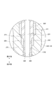
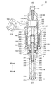
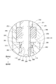
- FIG. 1 is a cross-sectional view showing the internal structure of the fuel injection valve according to the first embodiment.
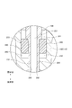
- FIG. 2 is an enlarged view showing the configuration of part A in FIG.
- FIG. 3 is a cross-sectional view showing the internal structure of the fuel injection valve according to the second embodiment.
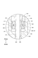
- FIG. 4 is an enlarged view showing the configuration of the portion B of FIG.
- FIG. 5 is a cross-sectional view showing a part of the internal structure of the fuel injection valve according to the third embodiment.
- FIG. 6 is a cross-sectional view showing a part of the internal structure of the fuel injection valve according to the fourth embodiment.
- FIG. 7 is a cross-sectional view showing a part of the internal structure of the fuel injection valve according to the fifth embodiment.
- the configuration of the fuel injection valve 10 according to the first embodiment will be described with reference to FIG.
- the fuel injection valve 10 is provided in an internal combustion engine (not shown) and is a device for injecting and supplying fuel to the internal combustion engine.
- As the fuel gaseous fuel, specifically hydrogen, is used in this embodiment.
- the fuel injection valve 10 includes a housing 100, a needle 200, a movable core 300, a fixed core 400, and a coil 600.
- the housing 100 is a member whose entire shape is formed as a substantially tubular container.
- FIG. 1 a state in which the housing 100 is oriented vertically along its longitudinal direction is depicted.
- the term "upper side” or the like may be used to indicate the upper side in FIG.
- a word such as “lower side” may be simply used to indicate the lower side in FIG.
- FIGS. 2 to 7 used in the following description.
- the fuel injected from the fuel injection valve 10 flows inside the housing 100 from the upper side to the lower side.
- the needle 200, the movable core 300, and the fixed core 400, which will be described later, are housed inside any of the housings 100.
- the housing 100 includes a first tubular member 110, a second tubular member 120, a third tubular member 130, a fourth tubular member 140, and a fifth tubular member 150. All of these are formed as substantially cylindrical members, and are arranged so that their central axes coincide with each other.
- the first tubular member 110 is a member of the housing 100 that is arranged at the most downstream position along the direction in which fuel flows.
- the first tubular member 110 is made of martensitic stainless steel and is subjected to a quenching treatment in order to increase its hardness.
- a space 111 is formed inside the first tubular member 110, and the needle 200 described later is housed in this space 111.
- the injection nozzle 500 is press-fitted inward and welded.
- the injection nozzle 500 forms a part of the housing 100, and has a cylindrical portion 520 and a closing portion 510.
- the cylindrical portion 520 is a portion formed in a cylindrical shape.
- the cylindrical portion 520 is fitted inside the first tubular member 110 with its central axis aligned with the central axis of the first tubular member 110.
- the inner peripheral surface 521 of the cylindrical portion 520 is a surface that slides in a state where the sliding contact portion 222 (described later) of the needle 200 is in contact with the inner peripheral surface 521.
- the closed portion 510 is a portion of the cylindrical portion 520 formed so as to close the lower end.
- a jet hole 511 is formed in the closed portion 510.
- the injection hole 511 is a through hole formed so as to penetrate the center of the closed portion 510 in the vertical direction of FIG.
- the injection hole 511 communicates the internal space 111 of the first tubular member 110 with the external space.
- the injection hole 511 is formed as an outlet for fuel injected from the fuel injection valve 10.
- a injection hole 511 for injecting fuel is formed at one end of the housing 100 in the longitudinal direction.
- a valve seat 512 is formed on the inner surface of the closed portion 510 so as to surround the periphery of the injection hole 511.
- the valve seat 512 is a portion that the seal portion 221 (described later) of the needle 200 abuts in order to close the injection hole 511.
- the entire injection nozzle 500 is made of martensitic stainless steel, and is subjected to quenching treatment in order to increase its hardness. Further, the portion of the injection nozzle 500 that the needle 200 abuts, that is, the valve seat 512 and the inner peripheral surface 521 is subjected to nitriding treatment. The inner peripheral surface 521 is further coated with a DLC coating for reducing the frictional force.
- the portion of the first tubular member 110 opposite to the injection nozzle 500, that is, the portion on the upper side is expanded in diameter, and the expanded cylindrical portion 112 is formed so as to extend further upward from the portion. ..
- the inner surface of the enlarged diameter cylindrical portion 112 is a portion that slides in a state where a part of the movable core 300 is in contact with the movable core 300, as will be described later. Therefore, the diameter-expanded cylindrical portion 112 is subjected to nitriding treatment.
- the lower end of the second tubular member 120 is connected to the upper end of the enlarged diameter cylindrical portion 112, that is, the upper end of the first tubular member 110.
- the second tubular member 120 is a cylindrical member of the housing 100 that is arranged at a position on the upstream side of the first tubular member 110 along the direction in which fuel flows.
- the inner diameter and outer diameter of the second tubular member 120 are equal to the inner diameter and outer diameter of the enlarged cylindrical portion 112, respectively.
- the second tubular member 120 is made of ferritic stainless steel, which is a magnetic material.
- the lower end of the third tubular member 130 is connected to the upper end of the second tubular member 120.
- the third tubular member 130 is a cylindrical member of the housing 100 that is arranged at a position on the upstream side of the second tubular member 120 along the direction in which fuel flows.
- the inner diameter and outer diameter of the third tubular member 130 are equal to the inner diameter and outer diameter of the second tubular member 120, respectively.
- the third tubular member 130 is made of austenitic stainless steel, which is a non-magnetic material.
- the lower end of the fourth tubular member 140 is connected to the upper end of the third tubular member 130.
- the fourth tubular member 140 is a cylindrical member of the housing 100 that is arranged at a position on the upstream side of the third tubular member 130 along the direction in which fuel flows.
- the inner diameter and outer diameter of the fourth tubular member 140 are equal to the inner diameter and outer diameter of the third tubular member 130, respectively.
- the fourth tubular member 140 is made of ferritic stainless steel, which is a magnetic material.
- the lower end portion of the fifth tubular member 150 is press-fitted inward and welded.
- the fifth tubular member 150 is a substantially cylindrical member arranged at a position on the most upstream side of the housing 100 along the direction in which fuel flows.
- the fifth tubular member 150 is made of austenitic stainless steel.
- An introduction port 153 is formed at the upper end of the fifth tubular member 150.
- the introduction port 153 is an opening formed as an inlet for fuel introduced from the outside.
- a filter 152 is provided at a position near the introduction port 153 in the space 151 formed inside the fifth tubular member 150.
- the filter 152 is for collecting foreign substances contained in the fuel introduced from the introduction port 153.
- the needle 200 is a rod-shaped member arranged inside the housing 100.
- the needle 200 is arranged so as to be movable along the longitudinal direction of the housing 100, that is, the vertical direction of FIG. 1 with its central axis moved to the central axis of the housing 100.
- the needle 200 is made of martensitic stainless steel and is quenched to increase its hardness.
- a seal portion 221 is formed at the end of the needle 200 on the injection nozzle 500 side.
- the needle 200 moves to the lowermost side of its movable range, the seal portion 221 comes into contact with the valve seat 512 as shown in FIG. 1, and the injection hole 511 is closed. As a result, the injection of fuel from the injection hole 511 is stopped. When the needle 200 moves upward and the seal portion 221 is separated from the valve seat 512, the injection hole 511 is opened. As a result, fuel is injected from the injection hole 511.
- the needle 200 is provided as a member for switching the opening and closing of the injection hole 511 by moving along the longitudinal direction inside the housing 100.
- the side in the direction in which the needle 200 moves so that the injection hole 511 is opened may also be referred to as a "valve opening side”.
- the side in the direction in which the needle 200 moves so that the injection hole 511 is closed that is, the lower side in FIG. 1, may also be referred to as a “valve closing side”.
- a plurality of sliding contact portions 222 protruding outward are formed at positions on the side surface of the needle 200 that are slightly closer to the valve opening side than the seal portion 221.
- the sliding contact portion 222 is a portion that slides in a state where the tip thereof is in contact with the inner peripheral surface 521 of the cylindrical portion 520.
- the plurality of sliding contact portions 222 are formed so as to be arranged along the circumferential direction of the needle 200.
- a recess is formed between the sliding contact portions 222 adjacent to each other as a path for fuel to pass through.
- the seal portion 221 and the sliding contact portion 222 are subjected to nitriding treatment.
- the sliding contact portion 222 is further coated with DLC. As a result, the frictional resistance between the sliding contact portion 222 and the inner peripheral surface 521 is reduced.
- the needle 200 is arranged in a state of penetrating the movable core 300 described later in the vertical direction.
- the upper end of the needle 200 is arranged further above the upper end of the movable core 300.
- a diameter-expanded portion 210 is formed on the side surface of the upper end portion of the needle 200 so as to project outward.
- the surface of the enlarged diameter portion 210 on the movable core 300 side, that is, the surface on the valve closing side is in contact with the end surface of the movable core 300.
- Space 201 is formed inside the needle 200.
- the space 201 is formed so as to extend from the valve opening side end portion of the enlarged diameter portion 210 of the needle 200 to a position closer to the valve closing side than the movable core 300.
- the space 201 is open to the outside.
- a plurality of through holes 202 are formed in the needle 200 at a position in the space 201 that is closer to the valve than the movable core 300.
- the space 201 and the space 111 are communicated with each other by the through hole 202.
- the movable core 300 is a member whose entire shape is formed into a substantially cylindrical shape.
- the movable core 300 is arranged in a state in which the central axis thereof is moved to the central axis of the housing 100 and is movable together with the needle 200 in the longitudinal direction of the housing 100, that is, in the vertical direction of FIG.
- the movable core 300 has a movable side high hardness portion 310 and a movable side low hardness portion 320.
- the movable side high hardness portion 310 is a substantially cylindrical portion arranged at a position where a part thereof is inside the movable side low hardness portion 320.
- the movable side high hardness portion 310 is made of martensitic stainless steel, which is a non-magnetic material and has a relatively high hardness.
- the movable side high hardness portion 310 is subjected to a quenching treatment in order to increase its hardness.
- a movable side through hole 313 is formed in the center of the movable side high hardness portion 310 so as to penetrate the movable side high hardness portion 310 in the vertical direction, that is, in the longitudinal direction of the housing 100.
- the needle 200 described above is inserted into the movable side through hole 313.
- the outer surface of the needle 200 is slidable in a state of being in contact with the inner surface of the movable side through hole 313.
- the inner surface of the movable side through hole 313 is subjected to nitriding treatment. Further, the outer surface of the needle 200 is also subjected to nitriding treatment and further DLC coated.
- the enlarged diameter portion 210 of the needle 200 is in contact with the end surface of the valve opening side of the movable side high hardness portion 310 from the upper side.
- a part of the end surface of the movable side high hardness portion 310 on the valve opening side is a portion that hits the fixed core 400 at the time of valve opening, as will be described later.
- nitriding treatment is applied to each of the portion where the enlarged diameter portion 210 of the needle 200 abuts and the portion where the fixed core 400 abuts. Further, the end face of the enlarged diameter portion 210 on the valve closing side is also subjected to nitriding treatment.
- the diameter of the valve closing side portion of the movable side high hardness portion 310 is expanded, and the diameter expanded portion 311 protruding toward the side is formed.
- the tip surface 312 of the diameter-expanded portion 311 is in contact with the inner surface of the diameter-expanded cylindrical portion 112 of the first tubular member 110.
- the tip surface 312 of the diameter-expanded portion 311 slides in contact with the inner surface of the diameter-expanded cylindrical portion 112.
- the tip surface 312 is nitrided and further DLC coated.
- the movable side low hardness portion 320 is a substantially cylindrical portion arranged at a position outside the movable side high hardness portion 310.
- the movable side low hardness portion 320 is fixed to the movable side high hardness portion 310 by so-called “driving" in a state where the inner surface thereof is in contact with the outer surface of the movable side high hardness portion 310.
- the valve closing side end face of the movable side low hardness portion 320 is in contact with the enlarged diameter portion 311 of the movable side high hardness portion 310.
- the movable side low hardness portion 320 is formed of ferritic stainless steel, which is a magnetic material. As a result, the movable side low hardness portion 320 has a lower hardness than the movable side high hardness portion 310.
- the position where the movable side low hardness portion 320 is arranged inside the housing 100 is a position substantially facing the second tubular member 120.
- the position of the valve opening side end face of the movable side low hardness portion 320 is slightly closer to the valve closing side than the position of the valve opening side end face of the movable side high hardness portion 310.
- the upper end surface of the movable side high hardness portion 310 protrudes slightly upward from the upper end surface of the movable side low hardness portion 320.
- the movable side high hardness portion 310 is formed so as to extend from the upper end portion of the movable core 300, which is one end portion along the longitudinal direction of the housing 100, to the lower end portion, which is the other end portion. Has been done.
- a plurality of through holes 301 are formed in the movable core 300 near the outer peripheral portion so as to penetrate the movable core 300 in the vertical direction.
- Each through hole 301 is formed so as to penetrate both the enlarged diameter portion 311 of the movable side high hardness portion 310 and the movable side low hardness portion 320. The function of the through hole 301 will be described later.
- the movable side low hardness portion 320 which is a part of the movable core 300, is formed of a magnetic material
- the movable side high hardness portion 310 which is another portion, is formed of a non-magnetic material. It is formed.
- the entire movable core 300 may be formed of a single material made of a magnetic material.
- the fixed core 400 is a member whose entire shape is formed in a substantially cylindrical shape.
- the fixed core 400 is fixed to the inside of the housing 100 in a state where the central axis thereof is moved to the central axis of the housing 100.
- the position where the fixed core 400 is provided is a position adjacent to the movable core 300 on the valve opening side.
- the fixed core 400 has a fixed side low hardness portion 420 and a fixed side high hardness portion 410.
- the fixed side low hardness portion 420 is a substantially cylindrical portion arranged at a position on the upper side of the movable core 300.
- the position where the fixed-side low hardness portion 420 is arranged inside the housing 100 is a position substantially opposite to the fourth tubular member 140.
- the outer surface of the low hardness portion 420 on the fixed side is fixed to the inner surface of the fourth tubular member 140 by welding.
- a through hole 421 is formed in the low hardness portion 420 on the fixed side so as to penetrate the low hardness portion 420 in the vertical direction.
- the fixed-side low-hardness portion 420 is formed of ferritic stainless steel, which is a magnetic material. As a result, the fixed-side low-hardness portion 420 has a lower hardness than the fixed-side high-hardness portion 410 described below.
- the fixed-side high-hardness portion 410 is a substantially cylindrical portion arranged at a position inside the fixed-side low-hardness portion 420, specifically, on the lower side of the through hole 421.
- the fixed-side high hardness portion 410 is made of martensitic stainless steel, which is a non-magnetic material and has a relatively high hardness.
- the high hardness portion 410 on the fixed side is subjected to a quenching treatment in order to increase its hardness.
- the end surface of the fixed-side high-hardness portion 410 on the movable core 300 side is a portion where the movable-side high-hardness portion 310 of the movable core 300 hits. Therefore, the end face is subjected to nitriding treatment.
- the fixed-side high-hardness portion 410 is fixed to the fixed-side low-hardness portion 420 by welding in a state where its outer surface is in contact with the inner surface of the fixed-side low-hardness portion 420.
- a fixed-side through hole 401 is formed in the center of the fixed-side high-hardness portion 410 so as to penetrate it in the vertical direction.
- the space 201 of the needle 200 described above is communicated with the space 151 of the fifth tubular member 150 via the fixed-side through hole 401 and the through hole 421.
- the enlarged diameter portion 210 of the needle 200 is inserted from below into the portion of the fixed-side through hole 401 on the movable core 300 side.
- the inner diameter of the fixed-side through hole 401 in the relevant portion is slightly larger than the inner diameter of the fixed-side through hole 401 in the other portion. Therefore, a gap is formed between the enlarged diameter portion 210 of the needle 200 and the inner surface of the fixed-side through hole 401.
- the position of the valve closing side end face of the fixed side low hardness portion 420 is slightly closer to the valve opening side than the position of the valve closing side end face of the fixed side high hardness portion 410.
- the lower end surface of the fixed side high hardness portion 410 projects slightly below the lower end surface of the fixed side low hardness portion 420, that is, toward the movable core 300 side.
- the entire lower end surface of the fixed side high hardness portion 410 faces the upper end surface of the movable side high hardness portion 310.
- the fixed-side low-hardness portion 420 which is a part of the fixed core 400, is formed of a magnetic material
- the fixed-side high-hardness portion 410 which is the other portion, is formed of a non-magnetic material. It is formed.
- the entire fixed core 400 may be formed of a single material made of a magnetic material.
- the coil 600 is supplied with an electric current to generate a magnetic force.
- the coil 600 is wound around the bobbin 610 and is arranged so as to cover the entire third tubular member 130 and a part of the fourth tubular member 140 of the housing 100 from the outside.
- a current is supplied to the coil 600, a magnetic circuit is formed so that magnetic flux passes through the fixed side low hardness portion 420, the movable side low hardness portion 320, the second tubular member 120, the fourth tubular member 140, and the like.
- a magnetic attraction is generated between the fixed core 400 and the movable core 300. Due to this magnetic attraction, the movable core 300 moves to the valve opening side together with the needle 200.
- the above magnetic attraction becomes zero.
- the movable core 300 moves to the valve closing side together with the needle 200 by the urging force of the spring 820 described later.
- the adjusting pipe 430 is press-fitted and fixed in the portion above the fixed-side high-hardness portion 410.
- the adjusting pipe 430 is a cylindrical member, and a through hole 431 that penetrates the adjusting pipe 430 in the vertical direction is formed inside the adjusting pipe 430.
- a spring 820 is arranged on the lower side of the adjusting pipe 430.
- the spring 820 is arranged substantially entirely inside the fixed-side through hole 401.
- the spring 820 is an elastic member whose expansion / contraction direction is along the vertical direction.
- One end of the spring 820 is in contact with the valve closing side end of the adjusting pipe 430.
- the other end of the spring 820 is in contact with the valve opening side end of the enlarged diameter portion 210 of the needle 200.
- the length of the spring 820 is shorter than the free length. Therefore, the enlarged diameter portion 210 of the needle 200 is pressed against the movable side high hardness portion 310 by the force from the spring 820. As a result, the spring 820 urges both the needle 200 and the movable core 300 to the valve closing side.
- a spring 810 is arranged on the lower side of the movable core 300.
- the spring 810 is an elastic member whose expansion / contraction direction is along the vertical direction.
- One end of the spring 810 is in contact with a stepped portion formed on the valve closing side end surface of the movable side high hardness portion 310.
- the other end of the spring 810 is in contact with a step portion of the first tubular member 110 formed near the end on the valve opening side. In this way, the spring 810 is arranged at a position between the movable core 300 and the housing 100.
- the length of the spring 810 is shorter than the free length. Therefore, the movable side high hardness portion 310 of the movable core 300 is pressed against the enlarged diameter portion 210 of the needle 200 by the force from the spring 810. As a result, the spring 810 urges both the needle 200 and the movable core 300 to the valve opening side. Since the spring 810 and the spring 820 are provided, the state in which the enlarged diameter portion 210 and the movable side high hardness portion 310 are in contact with each other is maintained.
- the urging force of the spring 820 is larger than the urging force of the spring 810. Therefore, when the supply of the current to the coil 600 is stopped and no magnetic attraction force is generated between the fixed core 400 and the movable core 300, the seal portion 221 of the needle 200 comes into contact with the valve seat 512. That is, the injection hole 511 is closed.
- a part of the coil 600, the fourth tubular member 140, and the fifth tubular member 150 is molded from the outside by the resin 900.
- a part of the resin 900 projects outward, and the protruding portion is formed as a connector 910.
- the connector 910 is a portion to which a wire for supplying a current to the coil 600 is connected.
- a power supply terminal 920 is arranged inside the connector 910.
- the power supply terminal 920 is a terminal provided at one end of a power supply line connected to the coil 600. The current is supplied to the coil 600 from the power supply terminal 920.
- a holder 700 is arranged outside the portion of the resin 900 in which the fourth tubular member 140 is molded.
- the holder 700 is a tubular member made of a magnetic material, and is formed so as to extend from a position outside the diameter-expanded cylindrical portion 112 to a position further on the valve opening side of the coil 600 on the valve opening side. ing.
- the cover 710 is arranged inside the holder 700 and at a position on the valve opening side of the coil 600.
- the cover 710 is a substantially circular tubular member made of a magnetic material, and is arranged so as to surround the fourth tubular member 140 from the outside.
- the portion of the cover 710 near the connector 910 is cut out to avoid interference with the connector 910. Therefore, in FIG. 1, the cross section of the cover 710 appears only at the position on the right side of the fourth tubular member 140.
- the holder 700 and the cover 710 form a part of a magnetic circuit through which the magnetic flux generated by the coil 600 passes.
- Fuel is supplied to the fifth tubular member 150 from the introduction port 153.
- the injection hole 511 is closed as described above. Therefore, the inside of the fuel injection valve 10 is in a state of being pressurized by the fuel.
- the fuel After flowing into the space 151 from the introduction port 153, the fuel passes through the through hole 431, the fixed side through hole 401, the space 201, the through hole 202, and the space 111 in this order, and is injected from the injection hole 511.
- the path through which the fuel passes is a path formed inside the housing 100, and corresponds to a "fuel passage" for guiding the fuel supplied from the outside to the injection hole 511.
- the circumference of the movable core 300 is filled with fuel.
- the fuel existing in the space on the valve opening side of the movable core 300 passes through the through hole 301 penetrating the movable core 300 and is closed more than the movable core 300.
- the space above and below the movable core 300 and the through hole 301 connecting them also correspond to a part of the fuel passage.
- the movable core 300 that started to move to the valve opening side then hits the fixed core 400 and stops.
- the upper end surface of the movable side high hardness portion 310 protrudes toward the fixed core 400 side
- the lower end surface of the fixed side high hardness portion 410 protrudes toward the movable core 300 side.
- the movable side high hardness portion 310 hits the fixed core 400
- the movable side low hardness portion 320 does not hit the fixed core 400.
- the movable core 300 hits the fixed side high hardness portion 410, but the movable core 300 does not hit the fixed side low hardness portion 420.
- the movable core 300 moves to the fixed core 400 side together with the needle 200 due to the generated magnetic attraction force, and the movable side has high hardness.
- the portion 310 is configured to hit the fixed side high hardness portion 410.
- the movable side high hardness portion 310 which is a relatively high hardness portion of the movable core 300
- the fixed side high hardness portion 410 which is a relatively hard portion of the fixed core 400
- the movable side low hardness portion 320 and the fixed side low hardness portion 420 which are the portions that contribute to the magnetic attraction force, are formed of a magnetic material having a relatively low hardness, but other members collide with them. It is configured not to.
- the fuel injection valve 10 has a configuration in which a magnetic material can be used to efficiently generate a magnetic attraction force, but the magnetic material is prevented from being damaged by collision.
- the magnetic attraction force does not work between the fixed core 400 and the movable core 300.
- the movable core 300 and the needle 200 move to the valve closing side by the urging force of the spring 820, and finally, the seal portion 221 is in contact with the valve seat 512, that is, the injection hole 511 is closed. .. As a result, the injection of fuel from the injection hole 511 is stopped.
- FIG. 2 is an enlarged view showing the configuration of part A in FIG.
- a first portion 231 and a second portion 232 are provided in a portion of the needle 200 below the enlarged diameter portion 210.
- the first portion 231 is a portion extending downward from the enlarged diameter portion 210, and has a relatively large outer diameter.
- the second portion 232 is a portion extending further downward from the lower end of the first portion 231 and whose outer diameter is smaller than the outer diameter of the first portion 231.
- the first part 231 corresponds to the "daikeibu" in the present embodiment.
- the second part 232 corresponds to the "small meridian part" in the present embodiment.
- the first portion 231 which is the large diameter portion and the second portion 232 which is the small diameter portion are provided so as to be arranged along the longitudinal direction of the housing 100 as described above.
- the vicinity of the lower end portion of the first portion 231 faces the inner peripheral surface of the first tubular member 110, and is supported by the inner peripheral surface in a slidable state.
- a portion where a part of the first portion 231 of the needle 200 and the inner peripheral surface of the first tubular member 110 face each other is hereinafter also referred to as a “sliding portion 271”.
- a gap of about several ⁇ m to several tens of ⁇ m is formed between the first portion 231 and the first tubular member 110.
- the needle 200 and the first tubular member 110 may be in contact with each other in a part thereof.
- a space is formed between the second portion 232 and the inner peripheral surface of the first tubular member 110. As will be described later, this space is a space that functions as a damper chamber 250 for attenuating the operating speed of the needle 200.
- the damper chamber 250 is a space formed around the second portion 232 in the vicinity of the upper end portion of the second portion 232 which is a small diameter portion.
- the portion below the damper chamber 250 protrudes toward the second portion 232 over the entire circumference.
- the portion that protrudes in this way is also referred to as a "protruding portion 260" below.
- the space 111 described above is a space below the protruding portion 260 in the inside of the first tubular member 110.
- the portion of the second portion 232 on the lower side of the damper chamber 250 faces the inner peripheral surface of the first tubular member 110, specifically, the inner peripheral surface of the protruding portion 260, and the inner circumference thereof. It is supported in a slidable state by the surface.
- Such a portion where a part of the second portion 232 of the needle 200 and the inner peripheral surface of the first tubular member 110 face each other is hereinafter also referred to as a “sliding portion 272”.
- a gap of about several ⁇ m to several tens of ⁇ m is formed between the second portion 232 and the protruding portion 260.
- the needle 200 and the first tubular member 110 may be in contact with each other in a part thereof.
- the protrusion 260 can also be said to be a wall for partitioning the lower end portion of the damper chamber 250.
- the through hole 202 described above is formed at a position on the needle 200 below the protrusion 260.
- the damper chamber 250 Since the damper chamber 250 is connected to the space 111 or the like which is a fuel passage, fuel flows in or out of the damper chamber 250. However, since the sliding portion 271 and the sliding portion 272 having a small gap are provided between the damper chamber 250 and the fuel passage, the inflow and outflow of fuel in the damper chamber 250 is restricted, and the damper chamber 250 is restricted. It is a semi-enclosed space.
- the needle 200 moves toward the valve opening side as described above. At that time, as the needle 200 moves, the volume of the damper chamber 250 increases, so that the fuel pressure in the damper chamber 250 decreases. Due to the pressure difference between the damper chamber 250 and the fuel passage, a force is applied to the needle 200 in the direction toward the valve closing side. As a result, a force that attenuates the operating speed in the same direction acts on the needle 200 and the movable core 300 that are moving in the direction toward the valve opening side. As a result, the collision energy when the needle 200 or the movable core 300, which is a movable member, collides with the fixed core 400, which is a fixed member, is reduced.
- the needle 200 moves toward the valve closing side as described above. At that time, as the needle 200 moves, the volume of the damper chamber 250 decreases, so that the fuel pressure in the damper chamber 250 increases. Due to the pressure difference between the damper chamber 250 and the fuel passage, a force is applied to the needle 200 in the direction toward the valve opening side. As a result, a force that attenuates the operating speed in the same direction acts on the needle 200 that is moving in the direction toward the valve closing side. As a result, the collision energy when the needle 200, which is a movable member, collides with the valve seat 512, which is a fixing member, is reduced even when the valve is closed.
- such a damper chamber 250 can be formed between the movable core 300 and the housing 100, specifically, at a position directly below the movable core 300, as in the conventional case.
- the spring constant of the spring 810 is not an appropriate value, resonance may occur inside the housing 100.
- the spring 810 is arranged at a portion of the inside of the housing 100 that can secure a relatively wide space, that is, at a position between the movable core 300 and the housing 100 as in the present embodiment.
- the damper chamber 250 for attenuating the operating speed of the needle 200 is located between the needle 200 and the housing 100, specifically, the second portion 232 and the first tubular member 110. It is formed in a position between them. Since it is not necessary to form a damper chamber at a position between the movable core 300 and the housing 100, a wide space for arranging the spring 810 can be secured at that position. As a result, it is possible to fully exert the effect of damping by the damper chamber 250 while securing a wide space for arranging the spring 810.
- the configuration of the fuel injection valve 10 as described above can also be adopted for the fuel injection valve for injecting liquid fuel.
- the viscosity of the fuel is small and the operating speed of the needle 200 or the like tends to be too high. Therefore, the effect of adopting the configuration of the present embodiment is great. ..
- each part of the fuel injection valve 10 tends to be brittle due to so-called hydrogen brittleness. If a movable member such as a needle 200 collides violently when hydrogen brittleness occurs, each part of the fuel injection valve 10 may be deformed due to wear or the like, and the operating characteristics of the fuel injection valve 10 may change in a short period of time. is there. Therefore, when hydrogen is used as the gaseous fuel, the effect of adopting the configuration of the fuel injection valve 10 as described above becomes particularly large.
- FIG. 3 shows the overall structure of the fuel injection valve 10 according to the present embodiment.
- FIG. 4 is an enlarged view of the configuration in part B of FIG.
- the fuel injection valve 10 according to the present embodiment is different from the first embodiment in the configuration of the portion shown in FIG.
- the diameter expanding member 240 is attached to the needle 200.
- the diameter-expanding member 240 is a member having a substantially cylindrical shape.
- the outer diameter of the diameter-expanding member 240 is larger than the outer diameter of the first portion 231.
- the inner diameter of the diameter-expanding member 240 is substantially equal to the outer diameter of the second portion 232.
- the second portion 232 of the needle 200 is inserted into the diameter-expanding member 240, and the upper end of the diameter-expanding member 240 is in contact with the lower end of the first portion 231.
- the diameter-expanding member 240 is fixed to the needle 200 at such a position by, for example, welding or press-fitting.
- the diameter expanding member 240 is a part of the needle 200.
- the diameter-expanding member 240 corresponds to the "large diameter portion" in the present embodiment.
- the outer diameter of the second portion 232 is smaller than the outer diameter of the diameter-expanding member 240, the second portion 232 corresponds to the "small warp portion" in the embodiment.
- the outer peripheral surface of the diameter-expanding member 240 faces the inner peripheral surface of the first tubular member 110, and is supported by the inner peripheral surface in a slidable state.
- the portion where the diameter-expanding member 240 of the needle 200 and the inner peripheral surface of the first tubular member 110 face each other in this way is also referred to as a "sliding portion 273" below.
- a gap of about several ⁇ m to several tens of ⁇ m is formed between the diameter-expanding member 240 and the first tubular member 110.
- the diameter-expanding member 240 and the first tubular member 110 may be in contact with each other in a part thereof.
- a space is formed between the second portion 232 and the inner peripheral surface of the first tubular member 110.
- the space is a space that functions as the damper chamber 250 in the present embodiment.
- the damper chamber 250 Since the damper chamber 250 is connected to the space 111 or the like which is a fuel passage, fuel flows in or out of the damper chamber 250. However, since the sliding portion 273 and the sliding portion 272 having a small gap are provided between the damper chamber 250 and the fuel passage, the inflow and outflow of fuel in the damper chamber 250 is restricted, and the damper chamber 250 is restricted. It is a semi-enclosed space.
- the damper chamber 250 is a space formed around the second portion 232 which is a small diameter portion.
- the upper portion of the damper chamber 250 is partitioned by the diameter expanding member 240, and the lower portion of the damper chamber 250 is partitioned by the protrusion 260. Even in such a configuration, the damper chamber 250 attenuates the operating speed of the movable core 300 and the needle 200.
- the area of the damper chamber 250 when viewed from above can be secured wider than in the case of the first embodiment. ing.
- the needle 200 in which the diameter-expanding member 240 is not provided is inserted into the movable side through hole 313 of the movable core 300 in advance, and then the diameter-expanding member 240 is attached to the needle 200. ..
- the area of the damper chamber 250 when viewed from above can be secured wider than the area of the movable side through hole 313.
- FIG. 5 is an enlarged view of a portion of the fuel injection valve 10 according to the present embodiment corresponding to the portion A in FIG.
- the present embodiment is different from the first embodiment in the configuration of the portion.
- a plurality of communication passages 233 are formed so as to penetrate the portion of the second portion 232 of the needle 200 adjacent to the damper chamber 250.
- the communication passage 233 is a through hole formed so as to communicate between the space 201 inside the needle 200, that is, the fuel passage and the damper chamber 250.
- the communication passage 233 is a passage that communicates between the fuel passage and the damper chamber 250, but is formed at a position different from the sliding portion 271 and the sliding portion 272, which can be said to be similar passages.
- FIG. 6 is an enlarged view of a portion of the fuel injection valve 10 according to the present embodiment, which corresponds to FIG. 4, that is, a portion corresponding to portion B of FIG.
- the present embodiment is different from the second embodiment in the configuration of the portion.
- a plurality of communication passages 241 are formed so as to vertically penetrate the portion of the diameter-expanding member 240 that protrudes outward from the first portion 231.
- the middle of each passage 241 is squeezed, and a squeezing portion 242 is formed.
- the communication passage 241 is a through hole formed so as to communicate between the space above the diameter-expanding member 240 in the fuel passage and the damper chamber 250.
- the communication passage 241 is a passage that communicates between the fuel passage and the damper chamber 250, but is formed at a position different from the sliding portion 273 and the sliding portion 272, which can be said to be similar passages.
- the needle 200 When the needle 200 operates, a part of the fuel passes through the communication passage 241 and moves back and forth between the damper chamber 250 and the space above the diameter-expanding member 240 in the fuel passage. Therefore, the formation of the communication passage 241 suppresses the function of the damper chamber 250, that is, the function of attenuating the operating speed of the needle 200.
- the operating speed of the needle 200 or the like is appropriately adjusted, and the needle 200 or the like is prevented from being decelerated too much. can do.
- FIG. 7 is an enlarged view of a portion of the fuel injection valve 10 according to the present embodiment, which corresponds to FIG. 4, that is, a portion corresponding to portion B of FIG.
- the present embodiment is different from the second embodiment in the configuration of the portion.
- a plurality of communication passages 261 are formed so as to penetrate the protrusion 260 up and down.
- the middle of each passage 261 is squeezed, and a squeezing portion 262 is formed.
- the communication passage 261 is a through hole formed so as to communicate between the space 111 below the protrusion 260 of the fuel passage and the damper chamber 250.
- the communication passage 261 is a passage that communicates between the fuel passage and the damper chamber 250, but is formed at a position different from the sliding portion 273 and the sliding portion 272, which can be said to be similar passages.
- the needle 200 When the needle 200 operates, a part of the fuel passes through the communication passage 261 and moves back and forth between the damper chamber 250 and the space 111 which is the fuel passage. Therefore, since the communication passage 261 is formed, the function of the damper chamber 250, that is, the function of attenuating the operating speed of the needle 200 is suppressed.
- the operating speed of the needle 200 or the like is appropriately adjusted to prevent the needle 200 or the like from being decelerated too much. can do.
Landscapes
- Engineering & Computer Science (AREA)
- Chemical & Material Sciences (AREA)
- Combustion & Propulsion (AREA)
- Mechanical Engineering (AREA)
- General Engineering & Computer Science (AREA)
- Chemical Kinetics & Catalysis (AREA)
- General Chemical & Material Sciences (AREA)
- Oil, Petroleum & Natural Gas (AREA)
- Analytical Chemistry (AREA)
- Physics & Mathematics (AREA)
- Electromagnetism (AREA)
- Fuel-Injection Apparatus (AREA)
Abstract
L'invention concerne une soupape d'injection de carburant (10) comprenant : un boîtier (100) dans lequel un trou d'injection (511) permettant d'injecter du carburant est formé à une extrémité dans la direction longitudinale ; une aiguille (200) qui commute l'ouverture et la fermeture du trou d'injection en se déplaçant dans la direction longitudinale à l'intérieur du boîtier ; un noyau fixe (400) qui est au moins partiellement formé d'un matériau magnétique et qui est fixé à l'intérieur du boîtier ; un noyau mobile (300) qui est au moins partiellement formé d'un matériau magnétique et qui est disposé dans un état pouvant se déplacer conjointement avec l'aiguille dans la direction longitudinale à l'intérieur du boîtier ; et une bobine (600) qui génère une force d'attraction magnétique entre le noyau fixe et le noyau mobile. Une chambre d'amortissement (250) servant à ralentir la vitesse de fonctionnement de l'aiguille est formée entre l'aiguille et le boîtier.
Priority Applications (1)
| Application Number | Priority Date | Filing Date | Title |
|---|---|---|---|
| DE112020002672.8T DE112020002672T5 (de) | 2019-06-06 | 2020-05-29 | Kraftstoffeinspritzventil |
Applications Claiming Priority (2)
| Application Number | Priority Date | Filing Date | Title |
|---|---|---|---|
| JP2019105868A JP7352384B2 (ja) | 2019-06-06 | 2019-06-06 | 燃料噴射弁 |
| JP2019-105868 | 2019-06-06 |
Publications (1)
| Publication Number | Publication Date |
|---|---|
| WO2020246385A1 true WO2020246385A1 (fr) | 2020-12-10 |
Family
ID=73653203
Family Applications (1)
| Application Number | Title | Priority Date | Filing Date |
|---|---|---|---|
| PCT/JP2020/021340 WO2020246385A1 (fr) | 2019-06-06 | 2020-05-29 | Soupape d'injection de carburant |
Country Status (3)
| Country | Link |
|---|---|
| JP (1) | JP7352384B2 (fr) |
| DE (1) | DE112020002672T5 (fr) |
| WO (1) | WO2020246385A1 (fr) |
Citations (3)
| Publication number | Priority date | Publication date | Assignee | Title |
|---|---|---|---|---|
| JP2015021470A (ja) * | 2013-07-23 | 2015-02-02 | マツダ株式会社 | 燃料噴射弁 |
| JP2016505746A (ja) * | 2012-11-02 | 2016-02-25 | マキャリスター テクノロジーズ、エルエルシー | 推力が増強された燃料噴射装置 |
| WO2017022163A1 (fr) * | 2015-08-06 | 2017-02-09 | 株式会社デンソー | Dispositif d'injection de carburant |
Family Cites Families (4)
| Publication number | Priority date | Publication date | Assignee | Title |
|---|---|---|---|---|
| JP2007023965A (ja) * | 2005-07-20 | 2007-02-01 | Denso Corp | 燃料噴射弁 |
| JP5482267B2 (ja) * | 2010-02-11 | 2014-05-07 | 株式会社デンソー | 燃料噴射弁 |
| JP6836955B2 (ja) * | 2017-04-28 | 2021-03-03 | 株式会社Soken | 燃料噴射弁 |
| JP2019105868A (ja) | 2017-12-08 | 2019-06-27 | エヌ・ティ・ティ・コムウェア株式会社 | 入力支援装置、入力支援方法、及びプログラム |
-
2019
- 2019-06-06 JP JP2019105868A patent/JP7352384B2/ja active Active
-
2020
- 2020-05-29 WO PCT/JP2020/021340 patent/WO2020246385A1/fr active Application Filing
- 2020-05-29 DE DE112020002672.8T patent/DE112020002672T5/de active Pending
Patent Citations (3)
| Publication number | Priority date | Publication date | Assignee | Title |
|---|---|---|---|---|
| JP2016505746A (ja) * | 2012-11-02 | 2016-02-25 | マキャリスター テクノロジーズ、エルエルシー | 推力が増強された燃料噴射装置 |
| JP2015021470A (ja) * | 2013-07-23 | 2015-02-02 | マツダ株式会社 | 燃料噴射弁 |
| WO2017022163A1 (fr) * | 2015-08-06 | 2017-02-09 | 株式会社デンソー | Dispositif d'injection de carburant |
Also Published As
| Publication number | Publication date |
|---|---|
| JP2020200766A (ja) | 2020-12-17 |
| JP7352384B2 (ja) | 2023-09-28 |
| DE112020002672T5 (de) | 2022-03-03 |
Similar Documents
| Publication | Publication Date | Title |
|---|---|---|
| WO2016163110A1 (fr) | Vanne d'injection de carburant | |
| JP4483940B2 (ja) | 燃料噴射弁 | |
| WO2018198592A1 (fr) | Soupape d'injection de combustible | |
| JP5482267B2 (ja) | 燃料噴射弁 | |
| JP6544416B2 (ja) | 燃料噴射弁 | |
| US11346307B2 (en) | Fluid injector and needle for a fluid injector | |
| WO2020246385A1 (fr) | Soupape d'injection de carburant | |
| CN114076052A (zh) | 具有多个阀针的气体喷射器 | |
| JP7311315B2 (ja) | 燃料噴射弁 | |
| EP3156638B1 (fr) | Injecteur de carburant | |
| JP7116609B2 (ja) | 燃料噴射弁 | |
| JP7152274B2 (ja) | 燃料噴射装置 | |
| JP7063741B2 (ja) | 燃料噴射弁 | |
| JP7284063B2 (ja) | 燃料噴射弁 | |
| JP7323444B2 (ja) | 燃料噴射弁 | |
| JP6566077B2 (ja) | 燃料噴射弁、及び、燃料噴射弁の製造方法 | |
| CN110651116B (zh) | 喷射器 | |
| JP7323445B2 (ja) | 燃料噴射弁 | |
| WO2019017097A1 (fr) | Vanne d'injection de carburant | |
| JP7376337B2 (ja) | 燃料噴射弁 | |
| JP2019203406A (ja) | 燃料噴射弁 | |
| WO2021044938A1 (fr) | Injecteur | |
| JP2012225185A (ja) | 燃料噴射弁 | |
| JP6090069B2 (ja) | 燃料噴射弁 | |
| JP4191760B2 (ja) | 燃料噴射弁 |
Legal Events
| Date | Code | Title | Description |
|---|---|---|---|
| 121 | Ep: the epo has been informed by wipo that ep was designated in this application |
Ref document number: 20819097 Country of ref document: EP Kind code of ref document: A1 |
|
| 122 | Ep: pct application non-entry in european phase |
Ref document number: 20819097 Country of ref document: EP Kind code of ref document: A1 |