WO2018193644A1 - 超音波除菌洗浄機 - Google Patents
超音波除菌洗浄機 Download PDFInfo
- Publication number
- WO2018193644A1 WO2018193644A1 PCT/JP2017/030240 JP2017030240W WO2018193644A1 WO 2018193644 A1 WO2018193644 A1 WO 2018193644A1 JP 2017030240 W JP2017030240 W JP 2017030240W WO 2018193644 A1 WO2018193644 A1 WO 2018193644A1
- Authority
- WO
- WIPO (PCT)
- Prior art keywords
- ultrasonic
- tank
- washing machine
- unit
- sterilized water
- Prior art date
- Legal status (The legal status is an assumption and is not a legal conclusion. Google has not performed a legal analysis and makes no representation as to the accuracy of the status listed.)
- Ceased
Links
Images




Classifications
-
- B—PERFORMING OPERATIONS; TRANSPORTING
- B08—CLEANING
- B08B—CLEANING IN GENERAL; PREVENTION OF FOULING IN GENERAL
- B08B3/00—Cleaning by methods involving the use or presence of liquid or steam
- B08B3/04—Cleaning involving contact with liquid
- B08B3/10—Cleaning involving contact with liquid with additional treatment of the liquid or of the object being cleaned, e.g. by heat, by electricity or by vibration
- B08B3/12—Cleaning involving contact with liquid with additional treatment of the liquid or of the object being cleaned, e.g. by heat, by electricity or by vibration by sonic or ultrasonic vibrations
Definitions
- the present invention relates to an ultrasonic sterilization washing machine.
- Patent Document 1 As cleaning machines using ultrasonic waves, cleaning machines described in Patent Document 1 and Patent Document 2 are known.
- Japanese Patent Publication Japanese Patent Laid-Open No. 2005-7215 (published on January 13, 2005)” Japanese Patent Publication “Japanese Laid-Open Patent Publication No. 2013-158768 (Released on August 19, 2013)”
- Patent Document 1 and Patent Document 2 have the following problems.
- the tank of the ultrasonic cleaner is filled with a cleaning agent.
- the cleaning agent contains sterilizing components such as chlorine.
- the sterilizing component volatilizes with time, and the sterilizing effect of the cleaning agent decreases with time. Therefore, in the ultrasonic cleaner of Patent Document 1, it is necessary to replace the old cleaning agent filled in the tank with a new cleaning agent in order to exert a sterilization effect. This has led to user effort and expense.
- the portable washer of Patent Document 2 can clean the object to be cleaned only in water.
- the present invention has been made in view of the above problems, and an object of the present invention is to realize an ultrasonic disinfection and washing machine with improved usability.
- an ultrasonic disinfecting and washing machine includes a disinfecting water generating unit that generates disinfecting water by electrolyzing a saline solution, and the disinfecting water includes An ultrasonic wave application unit that applies ultrasonic vibration to the supplied sterilization-cleaning object, and the sterilization water generation unit includes a first tank filled with the saline solution, and the first tank. A pair of electrodes provided in the interior of the sterilizer, wherein the sterilized water is generated by electrolyzing the saline with the pair of electrodes.
- generation part electrolyzes a salt solution, and is disinfecting water (it is less than a saline solution used as a raw material). Water with high chloric acid concentration). That is, the ultrasonic disinfecting / cleaning machine according to one aspect of the present invention only needs to electrolyze the saline solution to obtain the disinfecting water, and the cleaning agent is replaced each time the disinfecting / cleaning target is disinfected. Trouble and cost.
- the ultrasonic sterilization washing machine uses both the supply of the sterilized water to the sterilization cleaning target and the application of ultrasonic vibration to the sterilization cleaning target.
- the ultrasonic sterilization washing machine applies, for example, ultrasonic vibration to mold fungus that has settled in fine cracks such as wall caulking, and sterilizes the mold spores that have peeled off. It can be sterilized with water.
- the ultrasonic sterilization washing machine can improve the sterilization effect by the combined use of sterilized water and ultrasonic vibration.
- the ultrasonic disinfecting and washing machine according to one aspect of the present invention has an effect that usability can be improved.
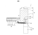
- FIG. 1 is a cross-sectional view of an ultrasonic sterilization washing machine 1 according to the first embodiment.
- the ultrasonic sterilization washing machine 1 sterilizes and cleans molds and the like attached to walls or clothes.
- the ultrasonic sterilization washing machine 1 includes a sterilized water generation unit 10, an ultrasonic application unit 20, a gripping unit 30, and a wiring arrangement unit 40.
- the sterilized water generation unit 10 generates water having a high hypochlorous acid concentration (hereinafter referred to as “sanitized water”) using saline as a raw material.
- Saline is a solution of sodium chloride in water.
- the ultrasonic sterilizer 1 mainly uses salt as a raw material, but may use a salt before purification as a raw material.
- the sterilized water generating unit 10 is attached to and detached from a first tank 11 filled with saline, a pair of electrodes 12 provided inside the first tank 11, and an opening 13 formed in the first tank 11. And a lid 14.
- the first tank 11 stores saline (or sterilized water).
- An opening 13 is formed in the first tank 11.
- a lid 14 is detachable from the opening 13.
- Saline as a raw material for the sterilized water is supplied into the first tank 11 from the opening 13.
- the opening 13 allows at least one of liquid (for example, tap water), gas (for example, hydrogen gas, oxygen gas, and chlorine gas generated during electrolysis), and solid (for example, salt) to pass therethrough.
- liquid for example, tap water
- gas for example, hydrogen gas, oxygen gas, and chlorine gas generated during electrolysis
- solid for example, salt
- the first tank 11 has a rectangular shape.
- the opening 13 is formed on the upper side of the first tank 11.
- a direction parallel to the direction of gravity is referred to as a horizontal direction.
- the first tank 11 has an opening 15 different from the opening 13.
- the sterilized water stored in the first tank 11 is supplied to the ultrasonic wave application unit 20 connected to the side surface of the sterilized water generation unit 10 through the opening 15.
- the opening 15 is formed on the side surface of the first tank 11.
- the first tank 11 is not limited to a specific shape and a specific material.
- the opening 13 is not limited to a specific size and a specific position.
- the pair of electrodes 12 includes a first electrode 12a and a second electrode 12b.
- the first electrode 12a and the second electrode 12b are metal electrodes, respectively.
- the 1st electrode 12a and the 2nd electrode 12b are provided by the non-diaphragm 1 tank type.
- One of the first electrode 12a and the second electrode 12b functions as an anode and the other functions as a cathode.
- the first electrode 12 a and the second electrode 12 b are provided on the lower surface of the first tank 11.
- the pair of electrodes 12 electrolyze the saline stored in the first tank 11. Chlorine gas is generated at the anode by electrolysis. Chlorine gas dissolves in water, producing hypochlorous acid. By adjusting the saline concentration, the hypochlorous acid concentration can be adjusted.
- the first electrode 12a and the second electrode 12b preferably have a structure that easily discharges oxygen gas and hydrogen gas generated by electrolysis.
- the first electrode 12a and the second electrode 12b may have a bar shape, a low-profile planar shape, a lath shape, a lattice shape, or the like.
- first electrode 12a and the second electrode 12b As a material of the first electrode 12a and the second electrode 12b, a metal that efficiently electrolyzes water, for example, any one metal (or an alloy thereof) of platinum, gold, palladium, rhodium, and iridium, Or it is preferable to use those oxides.
- electrodes having titanium surfaces coated with platinum are defined as first electrode 12a and second electrode 12b.
- the concentration of hypochlorite ions varies depending on the coating material that coats the metal constituting the anode.
- iridium oxide instead of platinum as a coating material, the amount of hypochlorous acid generated can be greatly increased even with the same current value.
- the pair of electrodes 12 may be arranged parallel to each other in the gravitational direction, may be arranged perpendicular to each other in the gravitational direction, and the installation position is not the lower surface of the first tank 11. Good.
- the pair of electrodes 12 may be a diaphragm electrolysis system.
- the ultrasonic wave application unit 20 applies ultrasonic vibration to the sterilization / cleaning object.
- the ultrasonic application unit 20 includes an ultrasonic element 21, an ultrasonic transmission unit 22, a sterilized water supply unit 23, a tube body 24, and a housing 25.
- the ultrasonic element 21 has a piezoelectric body that generates ultrasonic vibration when energized.
- the ultrasonic element 21 is electrically connected to the circuit unit 31 accommodated in the grip unit 30.
- a voltage is applied to the piezoelectric body of the ultrasonic element 21 from the battery 32 via the circuit unit 31.
- ultrasonic vibration having a predetermined frequency and a predetermined amplitude is generated.
- the ultrasonic application unit 20 is set so as to generate ultrasonic vibrations of 20 kHz to 40 kHz suitable for sterilization washing.
- the ultrasonic wave application unit 20 may generate ultrasonic vibration that is less than 20 kHz or greater than 40 kHz.
- the ultrasonic transmission unit 22 applies ultrasonic vibration to the sterilization / cleaning object.
- the ultrasonic transmission unit 22 is connected to the ultrasonic element 21 and transmits the ultrasonic vibration generated by the ultrasonic element 21 to the sterilization cleaning object.
- the ultrasonic transmission unit 22 is preferably formed from a metal material (aluminum, stainless steel, or the like).
- the ultrasonic transmission unit 22 extends in the horizontal direction from the ultrasonic element 21 to the end (or substantially end) of the housing 25.
- the ultrasonic transmission part 22 may be implement
- the sterilized water supply unit 23 supplies the sterilized water supplied from the first tank 11 to the sterilized cleaning object.
- the sterilized water supply unit 23 is provided around the ultrasonic transmission unit 22 that extends in the horizontal direction to the end surface of the ultrasonic transmission unit 22 that contacts the sterilization-cleaning target.
- the sterilized water supply unit 23 is formed of an organic material or an inorganic fiber material.
- organic materials include sponge materials (such as urethane sponge, melamine sponge, or cotton material) and fiber materials (such as non-woven fabric).
- fiber materials such as non-woven fabric.
- inorganic fiber materials include glass wool and steel wool. It is desirable that the sterilized water supply unit can be easily replaced by the user.
- the tube body 24 is disposed in parallel (or substantially in parallel) with the ultrasonic transmission unit 22.
- the tube body 24 extends from the opening 15 to the vicinity of the end face of the ultrasonic transmission unit 22.
- the sterilized water supplied to the tube body 24 through the opening 15 passes through the inside of the tube body 24 and is supplied to the vicinity of the end face of the ultrasonic transmission unit 22.
- the tube body 24 is formed of rubber or plastic.
- the tube body 24 may not be arranged in parallel (or substantially in parallel) with the ultrasonic transmission unit 22 as long as the sterilizing water is supplied near the end face of the ultrasonic transmission unit 22.
- the housing 25 accommodates the ultrasonic application unit 20, the ultrasonic element 21, the ultrasonic transmission unit 22, and the tube body 24 therein.
- the housing 25 is connected to the side surface of the first tank 11 of the ultrasonic wave application unit 20.
- An opening 15 is formed on the side surface of the first tank 11, and the sterilized water stored in the first tank 11 is supplied to the vicinity of the ultrasonic wave application unit via the opening 15 and the tube body 24.
- the sterilized water supplied into the housing 25 penetrates into the sterilized water supply unit 23.
- the sterilized water that has permeated the sterilized water supply unit 23 is supplied to the sterilized cleaning object.
- the gripping part 30 is a part where the user grips the ultrasonic sterilization washing machine 1 while using the ultrasonic sterilization washing machine 1.
- the gripping unit 30 is provided below the ultrasonic wave application unit 20.
- the grip portion 30 preferably has a shape suitable for the user to grip the ultrasonic sterilization washing machine 1.
- the grip part 30 includes a circuit part 31 and a battery 32 therein.
- the circuit unit 31 is a circuit that handles energization from the battery 32 to the pair of electrodes 12 and the ultrasonic element 21, and a known electric circuit may be used.
- the battery 32 is a power source that operates the pair of electrodes 12 and the ultrasonic element 21.
- a well-known power source can be used for the battery 32, but a direct current (DC) power source is more preferable.
- the battery specifications are determined by the required voltage level and the power consumption of the power supply. In the following description, the battery 32 is described as being a DC power source.
- the battery 32 may use a power supply method using a USB cable as a power source, or a removable battery (an alkaline battery, a nickel metal hydride battery). Since the charging method may be a conventional method, description thereof is omitted here.
- the wiring placement unit 40 includes wiring from the battery 32 to the pair of electrodes 12 and the ultrasonic element 21.
- the wiring arrangement unit 40 is provided between the circuit unit 31 and the sterilized water generation unit 10 and between the circuit unit 31 and the ultrasonic wave application unit 20.
- the first tank 11, the pair of electrodes 12 provided in the first tank 11, the circuit unit 31, and the battery 32 in a state where the user holds the grip unit 30. are sequentially arranged in the vertical direction.
- the first tank 11, the ultrasonic element 21, and the ultrasonic transmission unit 22 are sequentially arranged in the horizontal direction.
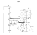
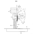
- FIG. 2 is a diagram for explaining a use situation of the ultrasonic sterilization washing machine 1.
- FIG. 3 is a flowchart for explaining a sterilization cleaning method using the ultrasonic sterilization cleaning machine 1.
- the user uses the ultrasonic sterilization washing machine 1 to sterilize and wash the mold 51 attached to the wall surface of the wall 50.
- the user grips the grip portion 30 of the ultrasonic sterilizer 1.
- the salt water used as the raw material of the sterilized water is stored in the first tank 11 (S10 in FIG. 3).
- Saline is prepared as follows.
- raw water is supplied to the first tank 11.
- Ordinary tap water can be used as the raw material water to be used.
- salt is added to the first tank 11.
- the amount of sodium chloride added is desirably 0.1% by weight or more and 3% by weight or less.
- a salt solution in which the amount of salt added is preset to 0.1 wt% or more and 3 wt% or less may be directly supplied to the first tank 11.
- the start switch (not shown) of the ultrasonic sterilizer 1 is turned on to start the ultrasonic sterilizer 1 (S20). Thereby, it supplies with electricity to a pair of electrode 12, and the electrolysis of salt solution starts in the disinfection water production
- the first electrode 12a is the anode and the second electrode 12b is the cathode of the pair of electrodes 12.
- energization of the ultrasonic element 21 is started after the electrolysis at the pair of electrodes 12 is completed. However, the energization of the ultrasonic element 21 may be performed simultaneously with the activation of the ultrasonic sterilization washing machine 1.
- the Cl 2 gas generated in the formula (2) easily dissolves in water and changes into hypochlorous acid and hypochlorite ions in the water as follows (formulas (3) and (4)).
- sterilized water having an increased concentration of hypochlorous acid is generated by electrolysis of the saline solution (S40, sterilized water generating step).
- the main sterilizing component of sterilized water is preferably sodium hypochlorite having an effective chlorine concentration of 5 ppm or more and 100 ppm or less. This is because the minimum concentration at which free spores such as fungi can be sterilized in a free state is 5 ppm, and when the concentration is 100 ppm or more, the user can easily feel a chlorine odor.
- a saline solution having an amount of raw material water of 100 mL and a salt addition amount of 1 g (1 wt%) is electrolyzed.
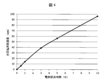
- FIG. 4 is a graph showing the relationship between electrolysis elapsed time and hypochlorous acid concentration.
- the horizontal axis represents electrolysis elapsed time (minutes), and the vertical axis represents hypochlorous acid concentration (ppm). Conditions such as the amount of salt added are as described above.
- energization to the pair of electrodes 12 is completed, and energization to the ultrasonic element 21 is started (S50).
- Whether the electrolysis is completed can be determined by several methods as follows. (1) It is considered that the electrolysis has been completed when a predetermined time has elapsed since the start switch was turned on. (2) A sensor (not shown) is installed in the first tank 11. The sensor detects hypochlorous acid concentration. The electrolysis is considered completed when the sensor detects that hypochlorous acid has reached a predetermined concentration.
- the ultrasonic transmission unit 22 is connected to the ultrasonic element 21 and transmits the ultrasonic vibration generated by the ultrasonic element 21 to the sterilization cleaning target (S70).
- the sterilization object to be cleaned is the mold 51 attached to the wall 50. The user presses the tip of the ultrasonic transmission unit 22 against the mold 51 and applies ultrasonic vibrations to the mold 51.
- sterilized water is supplied to the mold 51 (S80). Specifically, the sterilized water stored in the first tank 11 permeates through the opening 15 and the tube body 24 into the sterilized water supply unit 23 accommodated in the housing 25.
- the sterilized water supply unit 23 supplies sterilized water to the sterilized cleaning object.
- the sterilized water supply unit 23 is an inorganic fiber material (or an organic material)
- the dehumidified water penetrates into the inorganic fiber material through the opening 15 and the tube body 24. Therefore, the sterilized water can be supplied from the inorganic fiber material to the mold 51 by pressing the ultrasonic transmission unit 22 against the mold 51.
- the ultrasonic sterilization washing machine 1 performs sterilization washing of the mold 51 by using ultrasonic vibration and sterilized water together (S90, ultrasonic application step).
- the ultrasonic sterilization washing machine 1 applies ultrasonic vibration to the mold 51 that has settled in the fine cracks such as the caulking of the wall 50, and sterilizes the mold spores that have peeled off with sterilized water.
- the ultrasonic sterilization washing machine 1 can have the following effects by including the above-described configuration.
- the ultrasonic sterilization washing machine 1 uses saline as a raw material for sterilized water.
- the raw materials for saline are tap water and salt. Therefore, in the ultrasonic sterilization washing machine 1, the raw material of the sterilized water can be easily obtained and the operation cost can be suppressed.
- the ultrasonic sterilization washing machine 1 sterilized water (water having a high hypochlorous acid concentration) is obtained by electrolysis of water. Therefore, in the ultrasonic sterilization washing machine 1, the sterilized water can be easily generated, and the generation cost can be kept low. Furthermore, since the concentration of the saline solution can be easily adjusted, the concentration of hypochlorous acid can also be easily adjusted.
- the ultrasonic sterilization washing machine 1 is a problem of the conventional washing machine, that is, the problem that it is necessary to replace the old cleaning agent in the tank with a new cleaning agent in order to exert the sterilization effect. Can be solved. Moreover, since the ultrasonic sterilization washing machine 1 uses salt solution as a raw material, it has a specification that considers the health of the user as compared with a conventional washing machine that handles a cleaning agent.
- the ultrasonic sterilization washing machine 1 has the following effects. Specifically, in the ultrasonic sterilizer 1, the first tank 11, the pair of electrodes 12 provided in the first tank 11, the battery 32, and the circuit unit 31 in a state where the user holds the grip unit 30. Are sequentially arranged in the vertical direction. With this positional relationship, when the wall surface is sterilized and cleaned using the ultrasonic sterilizing and cleaning machine 1, the first tank 11 is placed at the highest position. Gases such as hydrogen, oxygen, and chlorine generated at the time of electrolysis or bubbles containing the gas move above the first tank 11 and are stored above the first tank 11 (see FIG. 2).
- the gas and / or bubbles are easily discharged from the first tank 11 when the lid 14 is opened and the saline solution, the raw material water or the salt solution is supplied to the first tank 11. Thereby, the influence which the said gas and / or foam has on the subsequent electrolysis can be suppressed. As a result, the usability of the ultrasonic sterilizer 1 is improved from the viewpoint of the safety of the ultrasonic sterilizer 1 and the sense of security felt by the user.
- the ultrasonic sterilization washing machine 1 is operated by the user holding the grip portion 30. Therefore, the ultrasonic sterilization and washing machine 1 can realize high operability with respect to the wall sterilization and cleaning object while improving safety. Moreover, since the concentration of hypochlorous acid contained in the sterilized water can be easily adjusted, the health of the user can be ensured. Therefore, for example, when disinfecting and cleaning caulking mold in the bathroom or dew mold in the window frame, the user can work for a long time.
- the ultrasonic sterilization washing machine 1 may use a rechargeable battery as the battery 32 and share a power source for energizing the pair of electrodes 12 and the ultrasonic element 21. With this configuration, the ultrasonic sterilizer 1 does not need a plurality of power supplies, and the ultrasonic sterilizer 1 can be downsized.
- the ultrasonic sterilization washing machine 1 may include a configuration in which the pair of electrodes 12 and the ultrasonic element 21 are energized at different timings.
- the design of the circuit unit 31 or (2) the electrical wiring from the battery 32 to the pair of electrodes 12 and the electrical wiring from the battery 32 to the ultrasonic element 21 are separated. It is feasible.
- the circuit configuration Simplification and downsizing of the machine can be realized at the same time.
- the ultrasonic sterilization washing machine 1 may have a configuration in which the polarity of the current flowing through the pair of electrodes 12 can be reversed.
- This configuration can be realized by designing the circuit unit 31.
- the effects of this configuration are as follows. Specifically, tap water that can be used as a raw material for saline contains a scale component (for example, calcium or magnesium).
- the circuit unit 31 reverses the polarity of the current. Thereby, the increase in the electrode resistance resulting from a scale component can be suppressed.
- the size of the ultrasonic sterilization washing machine 1 can be appropriately designed. Therefore, it becomes portable enough by making it small size. In that case, since the ultrasonic sterilization washing machine 1 improves portability, it is used in many scenes as compared with the case where it is used by being fixed in one place. As a result, the ultrasonic sterilization washing machine 1 can further improve usability.
- the ultrasonic sterilization washing machine 1 can exhibit various effects. This effect is the same also in the ultrasonic sterilization washing machine 2 etc. which are mentioned later.
- the ultrasonic sterilization washing machine 2 is the same as the ultrasonic sterilization washing machine 1 except that a trigger 45 (regulation unit) is provided.
- the trigger 45 regulates the supply of the sterilized water generated by the sterilized water generating unit 10 to the ultrasonic wave applying unit 20. This will be specifically described below.
- FIG. 5 is a cross-sectional view of the ultrasonic sterilization washing machine 2 according to the second embodiment.
- the trigger 45 is provided in the first tank 11, and the trigger 45 closes the opening 15 formed on the side surface of the first tank 11 when the trigger 45 is not operating. Thereby, the saline solution (or sterilized water) stored in the first tank 11 does not flow into the housing 25.
- the opening 15 is opened, and saline (or sterilized water) stored in the first tank 11 flows into the housing 25.
- the trigger 45 may operate through a user's manual operation, or may operate automatically when the ultrasonic sterilizer 1 is activated.
- the trigger 45 is electrolyzed. May operate automatically upon completion.
- trigger 45 may operate in various ways.
- the ultrasonic sterilizer 2 can easily adjust the amount of sterilized water and the amount of saline used as the raw material of the sterilized water according to the operation of the trigger 45.
- the usage amount of the saline solution decreases, the number of times of supplying the raw water or salt to the first tank 11 decreases. In this way, the labor of the user and the operating cost of the ultrasonic sterilization washing machine 2 can be suppressed.
- the trigger 45 may be appropriately designed in shape, material, or configuration as long as the above operation and effect are realized.
- an open / close valve may be used as an alternative to the trigger 45.
- the on / off valve can be opened and closed by pressing a switch (not shown) provided in the ultrasonic sterilizer 2.
- the on-off valve can achieve the same function as the trigger 45.
- the trigger 45 may be realized by a structure in which the trigger 45 is pulled to apply pressure to the sterilized water generation unit 10 side and the supply of the sterilized water to the tube body 24 is promoted.
- the shape of the tank for storing saline (or sterilized water) is different.
- the configuration is the same. Therefore, hereinafter, the first tank 16 and the water supply tank 17 of the ultrasonic sterilizer 3 will be described.
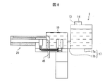
- FIG. 6 is a cross-sectional view of the ultrasonic sterilization washing machine 3 according to the third embodiment.
- the ultrasonic sterilization washing machine 3 includes a first tank 16 and a water supply tank 17.
- the first tank 16 and the water supply tank 17 are connected to each other and communicate with each other inside.
- the water supply tank 17 includes a water supply tank 17a and a water supply tank 17b.
- the water supply tank 17a and the water supply tank 17b are connected to each other and communicate with each other inside. Accordingly, the first tank 16, the water supply tank 17a, and the water supply tank 17b are connected to each other and communicated internally.
- the first tank 16 has a rectangular shape.
- the positional relationship among the ultrasonic wave application unit 20, the first tank 16, the water supply tank 17b, and the water supply tank 17a is arranged in the horizontal direction in that order.
- grip part 30, a pair of electrode 12, and the water supply tank 17 are arranged in a L-shaped direction, and the water supply tank 17 is located back seeing from the sterilization washing
- the water supply tank 17b is lower than the first tank 16 and the water supply tank 17a in the direction of gravity.
- the first tank 16 is lower than the water supply tank 17a.
- the first tank 16 may be higher than the water supply tank 17a or the same height.
- the first tank 16, the water supply tank 17a, and the water supply tank 17b store saline (or sterilized water).
- An opening 13 is formed in the water supply tank 17a.
- a lid 14 is detachable from the opening 13.
- Saline as a raw material for sterilized water is supplied to the water supply tank 17a through the opening 13, and stored in the first tank 16, the water supply tank 17a, and the water supply tank 17b.
- FIG. 7 is a diagram for explaining a use situation of the ultrasonic sterilizer 3.
- the ultrasonic sterilization washing machine 3 can sterilize the mold 62 of the clothes 61 placed on the floor 60.
- the user grips the grip portion 30 of the ultrasonic sterilization washing machine 3, presses the tip of the ultrasonic transmission portion 22 against the mold 62, and applies ultrasonic vibration to the mold 62.
- the ultrasonic application unit 20, the first tank 16, the water supply tank 17b, and the water supply tank 17a are arranged in the vertical direction in that order.
- the method for sterilizing and cleaning the mold 62 by the ultrasonic sterilizer 3 is performed in the same manner as described in the first and second embodiments, and thus the description thereof is omitted here.
- the ultrasonic sterilization washing machine 3 has the following effects by having the above configuration.
- the ultrasonic sterilization washing machine 3 When the ultrasonic sterilization washing machine 3 is used to sterilize the mold 62 of the clothes 61 placed on the floor 60, the ultrasonic application unit 20, the first tank 16, the water supply tank 17b, and the water supply tank 17a The positional relationship is as described above. With this positional relationship, the water supply tank 17a is positioned highest among the first tank 16, the water supply tank 17b, and the water supply tank 17a when the clothes 61 are sterilized and washed. Gases such as hydrogen, oxygen, and chlorine generated at the time of electrolysis or bubbles containing the gas move above the water supply tank 17a and are stored in the water supply tank 17a (see FIG. 7).
- This gas and / or foam is easily discharged from the water supply tank 17a when the lid 14 is opened to supply the saline to the water supply tank 17a. Thereby, the influence which the said gas and / or foam has on the subsequent electrolysis can be suppressed. As a result, the usability of the ultrasonic sterilization washing machine 3 is improved from the viewpoint of the safety of the ultrasonic sterilization washing machine 3 and the sense of security felt by the user.
- the clothes 61 are sterilized and washed in a state where there is an air reservoir in the first tank 16, the air in the first tank 16 moves to the water supply tank 17a side. The air is quickly discharged to the outside by opening the lid 14. Thus, the user feels secure from the viewpoint of improving safety.
- the ultrasonic sterilization washing machine 3 was placed on the floor or a desk or the like. Realizes high operability for sanitized objects such as cloth products. Moreover, since the concentration of hypochlorous acid contained in the sterilized water can be easily adjusted, the health of the user can be ensured. Therefore, for example, when disinfecting and cleaning black mold grown on a cloth product, the user can perform a long work.
- the first tank 16, the water supply tank 17a, and the water supply tank 17b have been described using different member names or member numbers. This is for convenience of explanation, and the first tank 16, the water supply tank 17a, and the water supply tank 17b may be collectively referred to as a first tank.
- Embodiment 4 The following description will discuss Embodiment 4 of the present invention with reference to FIGS. 8 and 9. For convenience of explanation, members having the same functions as those described in the above embodiment are denoted by the same reference numerals and description thereof is omitted.
- the shape of the tank for storing the saline solution (or sterilization water) is different.
- the configuration is the same. Therefore, hereinafter, the first tank 18 and the second tank 54 of the ultrasonic sterilization washing machine 4 will be described.
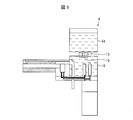
- FIG. 8 is a cross-sectional view of the ultrasonic sterilizer 4 according to the fourth embodiment.
- FIG. 9 is a diagram for explaining a use situation of the ultrasonic sterilization washing machine 4.
- the ultrasonic sterilization washing machine 4 includes a first tank 18 and a second tank 54. 8 and 9, the first tank 18 has a rectangular shape. An opening 13 is formed in the first tank 18. When the direction of gravity is the downward direction, the opening 13 is formed above the first tank 11 (upper surface in FIG. 8). The opening 13 is provided with a fitting portion 19 (described later).
- the second tank 54 is detachable from the first tank 18. Referring to FIG. 9, the second tank 54 has a rectangular shape.
- the 2nd tank 54 stores the salt solution used as the raw material of sanitization water.
- the second tank 54 includes a water stop valve 55.
- the water stop valve 55 is attached to one side surface of the second tank 54.
- the water stop valve 55 is detachable from the second tank 54.
- the user When supplying saline to the second tank 54, the user removes the water stop valve 55 from the second tank 54 and removes the water stop valve 55 from the opening obtained by removing the water stop valve 55 into the second tank 54. Feed water and salt).
- the user attaches the water stop valve 55 to the second tank 54.
- the water stop valve 55 Normally, the water stop valve 55 is closed so that the salt water stored in the second tank 54 does not leak.
- the water stop valve 55 opens the valve when connected to the corresponding fitting portion 19. More specific description will be given below.
- FIG. 8 shows a state in which the second tank 54 is attached to the first tank 18. Specifically, the surface of the second tank 54 on which the water stop valve 55 is provided faces downward. The water stop valve 55 of the second tank 54 is connected to the insertion portion 19 of the first tank 18. Thereby, the water stop valve 55 will be in the state which the valve opened.
- the saline solution stored in the second tank 54 is supplied into the first tank 18 through the water stop valve 55 and the filling portion 19.
- the water stop valve 55 is removed from the filling portion 19.
- the water stop valve 55 closes a valve.
- the filling portion 19 is normally closed and has a structure that opens when the water stop valve 55 is connected.
- the ultrasonic sterilization washing machine 4 has the following effects.
- the ultrasonic sterilization washing machine 4 can prepare the salt water used as the raw material of the sterilized water in the second tank 54 by providing the above configuration. Specifically, first, raw water and salt are supplied to the second tank 54. The salt is preferably supplied so as to be 0.1% by weight or more and 3% by weight or less. In this state, the second tank 54 is shaken. Thereby, salt can be easily dissolved and the salt solution concentration in the second tank 54 can be adjusted to be approximately the same as the salt concentration of the salt solution in the first tank 18. As a result, the saline concentration used for sterilization washing is stabilized. In this way, the ultrasonic sterilization washing machine 4 can easily adjust hypochlorous acid within a predetermined concentration range, thereby realizing stable sterilization washing.
- the 2nd tank 54, the filling part 19, and the water stop valve 55 may be implement
- FIG. 10 is a cross-sectional view of the ultrasonic sterilizer 5 according to the fifth embodiment.
- members having the same functions as those described in the above embodiment are denoted by the same reference numerals and description thereof is omitted.
- the ultrasonic sterilization washing machine 5 includes a sterilized water generation unit 10 a, an ultrasonic application unit 20, a gripping unit 30, and a wiring arrangement unit 40.
- a sterilized water generation unit 10 a when the gravity direction is a downward direction, the positional relationship among the gripping unit 30, the wiring placement unit 40, and the sterilized water generation unit 10 a is arranged in the order from top to bottom.
- the user of the ultrasonic sterilizer 5 may hold the sterilized water generator 10a (more specifically, the first tank 11a) when holding the ultrasonic sterilizer 5.
- the sterilized water generator 10a includes a pair of electrodes 12 and a first tank 11a.
- the pair of electrodes 12 includes a first electrode 12c and a second electrode 12d.
- the first electrode 12c and the second electrode 12d are fixed to the upper surface of the first tank 11a. Since the 1st electrode 12c and the 2nd electrode 12d may be the same as the 1st electrode 12a and the 2nd electrode 12b, those detailed explanation is omitted.
- the first tank 11a may be the same as the first tank 11 in material, shape, etc., and detailed description thereof is omitted.
- the ultrasonic sterilization washing machine 5 includes a tube body 24a.
- One end of the tube body 24 a is located inside the first tank 11 a, and the other end extends to the vicinity of the end face of the ultrasonic transmission unit 22 via the grip portion 30.
- the tube body 24 a may be disposed inside the grip portion 30, or may be provided so as to be exposed on the outer surface of the ultrasonic sterilizer 5.
- the ultrasonic sterilization washing machine 5 includes a trigger 45a and a pressurizing unit 46 connected to the trigger 45a.
- the trigger 45a and the pressurizing unit 46 operate as follows. Specifically, when the trigger 45a is pulled by the user, the pressurizing unit 46 connected to the trigger 45a pressurizes the air in the first tank 11a. When the air in the first tank 11a is pressurized, the supply of the sterilized water in the first tank 11a to the tube body 24a is promoted. The sterilized water is supplied to the sterilized water supply unit 23 through the inside of the tube body 24a.
- the trigger 45a and the pressure unit 46 may be realized by other configurations.
- a configuration may be adopted in which a push button (not shown) is provided and the above operation by the pressurizing unit 46 is realized by pressing the push button.
- the ultrasonic sterilization washing machine 5 has the following effects by having the above configuration.
- the first tank 11 a When the user uses the ultrasonic sterilizer 5, the first tank 11 a is normally located on the lower side and the gripping part 30 is located on the upper side. Accordingly, when the first tank 11a is sufficiently filled with saline (or sterilized water), the position of the center of gravity of the ultrasonic sterilization washing machine 5 is set higher than the position of the center of gravity of the ultrasonic sterilization washing machine 1. Can be lowered. Thereby, the rolling and the pitching at the time of operation of the ultrasonic sterilization washing machine 5 are reduced, and high operability of the ultrasonic sterilization washing machine 5 can be realized. In addition, when the amount of the saline solution is reduced, it becomes easy to add and use the solution on the way.
- one end of the tube body 24a is located near the lower surface of the first tank 11a.
- FIG. 11 is a cross-sectional view of the ultrasonic sterilization washing machine 6 according to the sixth embodiment.
- members having the same functions as those described in the above embodiment are denoted by the same reference numerals and description thereof is omitted.
- the position of the grip 30 is different, but the other configurations are the same. Therefore, the grip portion 30 of the ultrasonic sterilization washing machine 6 will be described below.
- the second tank 54, the first tank 18, and the grip portion 30 are arranged in the downward direction in that order.
- the gripping unit 30 is not disposed below the first tank 18 but is disposed on the side surface of the first tank 18.
- the ultrasonic application unit 20, the first tank 18, and the grip unit 30 are arranged in the horizontal direction in that order.
- the grip portion 30 may be disposed on the side surface of the first tank 18.
- the ultrasonic sterilization washing machine sterilizes molds and the like attached to walls or clothes. Since various cases are assumed for the location and position where mold or the like adheres, the shape of the ultrasonic sterilization washing machine may have various patterns accordingly.
- the ultrasonic application unit 20, the first tank 18, and the gripping unit 30 are arranged in the horizontal direction in that order.
- the second tank 54 is detachable from the first tank 18, and when the ultrasonic sterilizer 6 is used, the second tank 54 is replaced with the first tank 18. Can be removed from.
- ultrasonic sterilization washing machine 6 can be made into a horizontally long structure.
- a horizontally long structure means a structure in which the horizontal direction is longer than the vertical direction perpendicular to the horizontal direction.
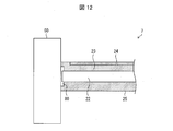
- FIG. 12 is a cross-sectional view of a main part of the ultrasonic sterilization washing machine 7 according to the seventh embodiment.
- members having the same functions as those described in the above embodiment are denoted by the same reference numerals and description thereof is omitted.
- the ultrasonic transmission unit 22 does not extend from the ultrasonic element 21 (not shown) to the end of the housing 25. This point is the ultrasonic transmission unit 22 of the ultrasonic sterilization washing machine 7, and the ultrasonic transmission unit 22 according to another ultrasonic sterilization washing machine that extends from the ultrasonic element 21 to the end of the housing 25. Is the difference.
- the sterilized water supply unit 23 is provided up to the end of the housing 25.
- the closed space portion 80 is formed between the wall 50 and the end surfaces of the sterilized water supply unit 23 and the ultrasonic transmission unit 22. Is done.
- the ultrasonic sterilization washing machine 7 When the ultrasonic sterilization washing machine 7 is used in this state, the sterilized water supplied from the sterilized water supply unit 23 is stored in the closed space unit 80, and the ultrasonic vibration of the ultrasonic transmission unit 22 is generated by the closed space unit 80. It is transmitted to the object to be sterilized and cleaned through the sterilized water stored in
- the ultrasonic sterilization washing machine 7 has the following effects by having the above configuration.
- an appropriate space can be provided between the end surface of the ultrasonic transmission unit 22 and the wall 50.
- the ultrasonic transmission part 22 can apply ultrasonic vibration with the distance which made the amplitude the maximum with respect to the wall 50 via the disinfection water which is a medium.
- the end surface of the ultrasonic transmission part 22 and the wall 50 do not contact
- the interval provided here (the interval between the end face of the ultrasonic transmission unit 22 and the wall 50) is preferably about 1 mm to 5 mm, and the amount of ultrasonic vibration generated is also taken into account in consideration of the amount of deformation of the sterilized water supply unit. It is preferred that the wall 50 is designed to lie in the abdominal part.
- the ultrasonic sterilization washing machine 7 transmits ultrasonic vibrations to the sterilization washing target object through the sterilization water. For this reason, the ultrasonic sterilization washing machine 7 effectively applies ultrasonic vibration to the mold 51 that has settled in the fine cracks such as caulking of the wall 50, and sterilized water against the mold spores that have peeled off. Can be sterilized.
- the ultrasonic sterilization washing machine 7 can increase the room for improving the sterilization washing efficiency by appropriately changing the shape and / or size of the closed space 80.
- the ultrasonic sterilization washing machine which concerns on aspect 1 of this invention is the sterilization water production
- the sterilized water generation unit is provided in a first tank filled with the saline and in the first tank.
- a pair of electrodes, and the sterilized water may be generated by the pair of electrodes electrolyzing the saline solution.
- the ultrasonic wave application unit includes an ultrasonic element that generates ultrasonic vibration when energized, and an ultrasonic vibration generated by the ultrasonic element. It is good also as a structure provided with the ultrasonic transmission part which transmits to the said sterilization washing
- the ultrasonic wave application unit further cleans the sterilized water generated in the sterilized water generation unit. It is good also as a structure provided with the disinfection water supply part supplied to a target object.
- the first tank includes one or a plurality of openings that allow at least one of liquid, gas, and solid to pass through. It is good also as a structure.
- the ultrasonic disinfection and washing machine includes the second tank that is attachable to and detachable from the first tank in the aspect 2 or 5, and the second tank is connected to the first tank.
- the inside may be configured to communicate with each other.
- the ultrasonic sterilization washing machine in any one of the above aspects 1 to 6, to the ultrasonic application unit of the sterilized water generated in the sterilized water generation unit. It is good also as a structure provided with the control part which controls supply of this.
- the ultrasonic disinfection and washing machine according to aspect 8 of the present invention is the ultrasonic disinfection washing machine according to any one of the above aspects 1 to 7, wherein the disinfection water generating unit and the ultrasonic wave application unit are energized from the same power source, and Alternatively, the power may be supplied at different timings.
- the ultrasonic disinfection washing machine which concerns on aspect 9 of this invention is the structure in which the said disinfection water production
- the ultrasonic sterilization washing machine may include a circuit unit that inverts the polarity of the current supplied to the sterilized water generating unit in any one of the first to ninth aspects. Good.
- the ultrasonic sterilization washing machine according to aspect 11 of the present invention may be configured such that in the above aspect 4, the sterilized water supply unit is provided around the ultrasonic transmission unit.
- the ultrasonic sterilization washing machine may have a configuration in which the sterilized water supply unit is formed of an inorganic fiber material in any one of the above aspects 4 or 11.
- the ultrasonic sterilization and washing machine according to the thirteenth aspect of the present invention may be configured to have a built-in rechargeable battery and be portable in any one of the above aspects 1 to 12.
- the ultrasonic sterilization washing machine supplies the closed space portion formed by the ultrasonic transmission unit, the sterilized water supply unit, and the sterilization / cleaning object in the above aspect 11. It is good also as a structure by which ultrasonic vibration is applied with respect to the said sterilization washing
- the ultrasonic sterilization cleaning method includes a sterilized water generation step of generating sterilized water by electrolyzing a saline solution, and the sterilization water generated in the sterilized water generation step.
- Ultrasonic sterilization washing machine 10 10a Bacteria-free water generation unit 11, 11a, 16, 18 First tank 12 Electrodes 12a, 12c First electrodes 12b, 12d Second electrodes 13, 15 Openings 17, 17a, 17b Water supply tank 19 Insertion unit 20 Ultrasonic application unit 21 Ultrasonic element 22 Ultrasonic transmission unit 23 Disinfecting water supply unit 24, 24a Tube body 25 Housing 30 Grasping unit 31 Circuit unit 32 Battery 40 Wiring arrangement unit 46 Pressurization Part 54 second tank 55 stop valve 80 closed space part
Landscapes
- Detail Structures Of Washing Machines And Dryers (AREA)
- Cleaning By Liquid Or Steam (AREA)
- Water Treatment By Electricity Or Magnetism (AREA)
- Apparatus For Disinfection Or Sterilisation (AREA)
- Detergent Compositions (AREA)
Abstract
使用性を改善した超音波除菌洗浄機(1)を実現する。食塩水を電気分解することにより除菌水を生成する除菌水生成部(10)と、上記除菌水が供給される除菌洗浄対象物に対して超音波振動を印加する超音波印加部(20)と、を備え、上記除菌水生成部(10)は、上記食塩水が充填される第1タンク(11)と、上記第1タンクの内部に設けられる一対の電極(12)と、を備え、上記除菌水は、上記一対の電極(12)が上記食塩水を電気分解することにより生成される。
Description
本発明は、超音波除菌洗浄機に関する。
超音波を用いた洗浄機として特許文献1、及び特許文献2に記載の洗浄機が知られている。
しかしながら、特許文献1、及び特許文献2の技術には以下の問題がある。
特許文献1の超音波クリーナが除菌目的で使用される場合、上記超音波クリーナのタンクに洗浄剤が充填される。その洗浄剤には塩素等の除菌成分が含まれる。当該除菌成分は時間の経過ともに揮発し、上記洗浄剤の除菌効果が時間の経過とともに低下する。そのため、特許文献1の超音波クリーナでは、除菌効果を発揮するために、上記タンク内に充填された古い洗浄剤を新しい洗浄剤に交換する必要がある。そのことがユーザに手間と費用をもたらしていた。
特許文献2の携帯用洗浄機は、水中のみでしか洗浄対象を洗浄することができない。
本発明は、上記の問題点に鑑みてなされたものであり、その目的は、使用性を改善した超音波除菌洗浄機を実現することにある。
上記の課題を解決するために、本発明の一態様に係る超音波除菌洗浄機は、食塩水を電気分解することにより除菌水を生成する除菌水生成部と、上記除菌水が供給される除菌洗浄対象物に対して超音波振動を印加する超音波印加部と、を備え、上記除菌水生成部は、上記食塩水が充填される第1タンクと、上記第1タンクの内部に設けられる一対の電極と、を備え、上記除菌水は、上記一対の電極が上記食塩水を電気分解することにより生成される構成である。
上記の構成によれば、本発明の一態様に係る超音波除菌洗浄機では、除菌水生成部が、食塩水を電気分解することにより除菌水(原料となる食塩水よりも次亜塩素酸濃度の高い水)を生成する。つまり、本発明の一態様に係る超音波除菌洗浄機は、除菌水を得るために食塩水を電気分解すればよく、上記除菌洗浄対象物を除菌洗浄するたびに洗浄剤を交換する手間、及び費用が発生しない。
加えて、本発明の一態様に係る超音波除菌洗浄機は、上記除菌洗浄対象物に対する上記除菌水の供給と、上記除菌洗浄対象物に対する超音波振動の印加とを併用する。これにより、本発明の一態様に係る超音波除菌洗浄機は、例えば、壁面のコーキングなどの微細割れに住み着いたカビ菌に対して超音波振動を印加し、剥がれ落ちたカビ胞子を除菌水により除菌することができる。
このように、上記の構成によれば、本発明の一態様に係る超音波除菌洗浄機は、除菌水及び超音波振動の併用により、除菌効果を改善することができる。
本発明の一態様に係る超音波除菌洗浄機は、使用性を改善することができるという効果を奏する。
〔実施形態1〕
実施形態1に係る超音波除菌洗浄機1を図1~図3により説明する。図1は、実施形態1に係る超音波除菌洗浄機1の断面図である。
実施形態1に係る超音波除菌洗浄機1を図1~図3により説明する。図1は、実施形態1に係る超音波除菌洗浄機1の断面図である。
〔超音波除菌洗浄機1の構成〕
超音波除菌洗浄機1は、壁または衣服等に付着したカビ等を除菌洗浄する。図1を参照して、超音波除菌洗浄機1は、除菌水生成部10と、超音波印加部20と、把持部30と、配線配置部40と、を備える。
超音波除菌洗浄機1は、壁または衣服等に付着したカビ等を除菌洗浄する。図1を参照して、超音波除菌洗浄機1は、除菌水生成部10と、超音波印加部20と、把持部30と、配線配置部40と、を備える。
<除菌水生成部10>
除菌水生成部10は、食塩水を原料として次亜塩素酸濃度の高い水(以降、「除菌水」と称する。)を生成する。食塩水とは、水に食塩を溶かした溶液のことである。超音波除菌洗浄機1は、主に食塩を原料として使用するが、精製前の塩を原料として使用してもよい。
除菌水生成部10は、食塩水を原料として次亜塩素酸濃度の高い水(以降、「除菌水」と称する。)を生成する。食塩水とは、水に食塩を溶かした溶液のことである。超音波除菌洗浄機1は、主に食塩を原料として使用するが、精製前の塩を原料として使用してもよい。
除菌水生成部10は、食塩水が充填される第1タンク11と、第1タンク11の内部に設けられる一対の電極12と、第1タンク11に形成された開口部13に脱着される蓋14と、を備える。
第1タンク11は、食塩水(又は、除菌水)を貯留する。第1タンク11には開口部13が形成されている。開口部13には蓋14が脱着可能である。除菌水の原料となる食塩水は、開口部13から第1タンク11内に供給される。開口部13は、液体(例えば、水道水)、気体(例えば、電気分解時に発生する水素ガス、酸素ガス、塩素ガス)、及び固体(例えば、食塩)の少なくとも何れか1つを通過させる。開口部13は、1または複数形成されていてよい。
第1タンク11は直方形状である。図1において重力方向を下側とした場合、開口部13は、第1タンク11の上側に形成されている。なお、以下の説明において、重力方向に平行な方向を水平方向と称する。
第1タンク11には、開口部13とは異なる開口部15が形成されている。第1タンク11に貯留された除菌水は、開口部15を介して、除菌水生成部10の側面に連結された超音波印加部20に供給される。図1では、開口部15は、第1タンク11の側面に形成されている。
なお、第1タンク11は、特定の形状、及び特定の材質に限定されない。開口部13は、特定の大きさ、及び特定の位置に限定されない。
一対の電極12は、第1電極12a、及び第2電極12bを含む。第1電極12a、及び第2電極12bは、それぞれ金属電極である。第1電極12a、及び第2電極12bは、無隔膜一槽式で設けられる。第1電極12a、及び第2電極12bは、一方が陽極、他方が陰極として機能する。第1電極12a、及び第2電極12bは、第1タンク11の下面に設けられている。
一対の電極12は、第1タンク11に貯留された食塩水を電気分解する。電気分解により陽極に塩素ガスが発生する。塩素ガスは水に溶け、次亜塩素酸が生成する。食塩水濃度を調整することで、次亜塩素酸濃度を調整することができる。第1電極12a、及び第2電極12bは、好ましくは、電気分解で発生する酸素ガス、及び水素ガスを排出しやすい構造を有する。第1電極12a、及び第2電極12bは、例えば、棒状、低背の平面状、ラス形状、又は格子形状等の形状であってよい。
第1電極12a、及び第2電極12bの材料としては、水を効率的に電気分解する金属、例えば、白金、金、パラジウム、ロジウム、及びイリジウムのうちいずれか1つの金属(またはその合金)、又はそれらの酸化物を使用することが好ましい。例えば、チタンからなる電極の表面を白金でコートした電極を第1電極12a、及び第2電極12bとする。次亜塩素酸イオンの濃度は、陽極を構成する金属をコートするコート素材によって異なる値を示す。白金の代わりに例えば酸化イリジウムをコート素材として使用することで、同じ電流値であっても次亜塩素酸の発生量を大幅に増加させることができる。
なお、一対の電極12は、重力方向に対して互いに平行に配置してもよいし、重力方向に対して互いに垂直に配置しても良く、設置位置が第1タンク11の下面でなくてもよい。また、一対の電極12は、有隔膜電解方式であってもよい。
続いて、第1タンク11の側面に連結された超音波印加部20について説明する。
<超音波印加部20>
超音波印加部20は、除菌洗浄対象物に対して超音波振動を印加する。超音波印加部20は、超音波素子21と、超音波伝達部22と、除菌水供給部23と、チューブ体24と、筐体25と、を備える。
超音波印加部20は、除菌洗浄対象物に対して超音波振動を印加する。超音波印加部20は、超音波素子21と、超音波伝達部22と、除菌水供給部23と、チューブ体24と、筐体25と、を備える。
超音波素子21は、通電により超音波振動を生じる圧電体を有する。超音波素子21は把持部30に収容された回路部31と電気的に接続されている。超音波素子21の上記圧電体は、回路部31を介して、バッテリ32から電圧が印加される。圧電体に電圧が印加されると、所定の周波数、及び所定の振幅の超音波振動が発生する。超音波除菌洗浄機1では、超音波印加部20は、除菌洗浄に適した20kHz以上40kHz以下の超音波振動が発生するように設定されている。ただし、超音波印加部20は、20kHz未満、又は40kHzよりも大きい超音波振動を発生してもよい。
超音波伝達部22は、除菌洗浄対象物に対して超音波振動を印加する。具体的に、超音波伝達部22は、超音波素子21に連結し、超音波素子21が発生させた超音波振動を除菌洗浄対象物に伝達する。超音波伝達部22は、好ましくは、金属材料(アルミニウム、又はステンレス等)から形成される。超音波伝達部22は、超音波素子21から筐体25の端部(又は、略端部)まで水平方向に延伸する。なお、超音波伝達部22は、超音波素子21が発生させた超音波振動を除菌洗浄対象物に伝達するのでれば、他の構成で実現されてもよい。
除菌水供給部23は、第1タンク11から供給された除菌水を除菌洗浄対象物に供給する。除菌水供給部23は、除菌洗浄対象物と接触する超音波伝達部22の端面まで、水平方向に延伸する超音波伝達部22の周囲に設けられている。
除菌水供給部23は、有機系素材、又は無機系繊維材で形成される。有機系素材の一例として、スポンジ材(ウレタンスポンジ、メラミンスポンジ、又はコットン材等)、繊維素材(不織布等)が挙げられる。無機系繊維材の一例として、グラスウール、又はスチールウール等が挙げられる。なお、上記除菌水供給部はユーザ自身が容易に交換可能であることが望ましい。
チューブ体24は、超音波伝達部22と平行(又は、略平行)に配設されている。チューブ体24は、開口部15から超音波伝達部22の端面付近まで伸びている。開口部15を介してチューブ体24に供給された除菌水は、チューブ体24の内部を通って、超音波伝達部22の端面付近に供給される。
チューブ体24は、ゴム、又はプラスチック等で形成されている。チューブ体24は、超音波伝達部22の端面付近に除菌水を供給するのであれば、超音波伝達部22と平行(又は、略平行)に配設されていなくてもよい。
筐体25は、超音波印加部20、超音波素子21、超音波伝達部22、及びチューブ体24を内部に収容する。筐体25は、超音波印加部20の第1タンク11の側面に連結する。第1タンク11の側面には開口部15が形成されており、第1タンク11に貯留された除菌水は、開口部15及びチューブ体24を介して、超音波印加部の近傍まで供給される。筐体25の内部に供給された除菌水は除菌水供給部23に浸透する。除菌水供給部23に浸透した除菌水は、除菌洗浄対象物に供給される。
<把持部30>
把持部30は、ユーザが、超音波除菌洗浄機1の使用中に超音波除菌洗浄機1を把持する部分である。把持部30は、超音波印加部20の下方に設けられる。把持部30は、好ましくは、ユーザが超音波除菌洗浄機1を把持するのに好適な形状を有する。把持部30は、その内部に、回路部31と、バッテリ32と、を備える。
把持部30は、ユーザが、超音波除菌洗浄機1の使用中に超音波除菌洗浄機1を把持する部分である。把持部30は、超音波印加部20の下方に設けられる。把持部30は、好ましくは、ユーザが超音波除菌洗浄機1を把持するのに好適な形状を有する。把持部30は、その内部に、回路部31と、バッテリ32と、を備える。
回路部31は、バッテリ32から一対の電極12、及び超音波素子21への通電を扱う回路であり、公知の電気回路が使用されてよい。
バッテリ32は、一対の電極12、及び超音波素子21を動作させる電源である。バッテリ32は、周知の電源を用いることができるが、直流(DC)電源とすることがより好ましい。電池の仕様は、必要な電圧レベルと電源の消費電力とによって決まる。以下の説明では、バッテリ32は直流電源であるものとして説明する。
なお、バッテリ32は、電源としてUSBケーブルに依る給電方式、又は取り外し可能な電池(アルカリ電池、ニッケル水素充電池)を使用してもよい。充電の方法は、従来の方法でよいため、ここでの説明は省略する。
<配線配置部40>
配線配置部40は、バッテリ32から一対の電極12、及び超音波素子21までの配線を含む。配線配置部40は、回路部31と除菌水生成部10との間、及び回路部31と超音波印加部20との間に設けられる。
配線配置部40は、バッテリ32から一対の電極12、及び超音波素子21までの配線を含む。配線配置部40は、回路部31と除菌水生成部10との間、及び回路部31と超音波印加部20との間に設けられる。
このように、超音波除菌洗浄機1では、ユーザが把持部30を把持した状態で、第1タンク11、第1タンク11内に設けられた一対の電極12、回路部31、及びバッテリ32が鉛直方向に順次配列する。また、超音波除菌洗浄機1では、第1タンク11、超音波素子21、及び超音波伝達部22が、水平方向に順次配列する。
〔超音波除菌洗浄機1の動作(使用方法)〕
超音波除菌洗浄機1の動作を図2、及び図3により説明する。図2は、超音波除菌洗浄機1の使用状況を説明するための図である。図3は、超音波除菌洗浄機1を用いた除菌洗浄方法を説明するフローチャートである。
超音波除菌洗浄機1の動作を図2、及び図3により説明する。図2は、超音波除菌洗浄機1の使用状況を説明するための図である。図3は、超音波除菌洗浄機1を用いた除菌洗浄方法を説明するフローチャートである。
ユーザは、壁50の壁面に付着したカビ51を除菌洗浄するために超音波除菌洗浄機1を使用する。ユーザは、超音波除菌洗浄機1の把持部30を把持する。
まず、第1タンク11に、除菌水の原料となる食塩水を貯留する(図3のS10)。食塩水は、次のように準備される。
最初に、第1タンク11に原料水を供給する。使用する原料水として、普通の水道水を用いることができる。一例として、日本国大阪府八尾市の水道水(pH=7.6、硬度45mg/L、初期次亜塩素酸濃度=0.1ppm)を用いることができる。次に、第1タンク11に食塩を添加する。食塩の添加量は、0.1重量%以上、3重量%以下とすることが望ましい。食塩の添加量が0.1重量%以上、3重量%以下に予め設定された食塩水を第1タンク11に直接供給してもよい。
続いて、超音波除菌洗浄機1の起動スイッチ(不図示)をONにして、超音波除菌洗浄機1を起動する(S20)。これにより、一対の電極12に通電し、除菌水生成部10において食塩水の電気分解が開始する(S30)。以下では、一対の電極12のうち、第1電極12aが陽極、第2電極12bが陰極であるものとして説明する。また、一対の電極12での電気分解が完了した後で、超音波素子21への通電が開始するものとする。ただし、超音波素子21への通電は、超音波除菌洗浄機1の起動と同時であってもよい。
除菌水生成部10において食塩水の電気分解が開始すると、陽極である第1電極12aでは水素イオン(H+)、酸素ガス、及び塩素ガスが発生する(式(1)及び、式(2))。


式(2)において発生するCl2ガスは容易に水に溶け、次のように水中において次亜塩素酸、及び次亜塩素酸イオンに変化する(式(3)及び、式(4))。


このように、食塩水の電気分解により、次亜塩素酸の濃度が増加した除菌水が生成される(S40。除菌水生成ステップ)。
除菌水の主要除菌成分は、有効塩素濃度で5ppm以上、100ppm以下の次亜塩素酸ナトリウムであることが望ましい。この理由として、カビ等の有胞子菌を遊離状態で除菌できる最低濃度が5ppmである点、及び、100ppm以上の濃度になるとユーザが塩素臭を感じやすくなる点が挙げられる。
一例として、原料水量100mL、食塩添加量1g(1wt%)の食塩水を電気分解する。電極サイズ:Φ1mm、L=30mmの白金コートチタン電極を陽極と陰極で対極させ、直流5Vで電気分解を行う(電流値=150mA~170mA)。この条件下では図4に示すように、1分程度の電気分解で約10ppm、3分程度の電気分解で約35ppmの次亜塩素酸ナトリウムが生成される。
図4は、電解経過時間と次亜塩素酸濃度との関係を示すグラフである。横軸が電解経過時間(分)、縦軸が次亜塩素酸濃度(ppm)である。食塩添加量等の条件は上述したとおりである。
上記電気分解が完了すると、一対の電極12への通電が終了し、超音波素子21への通電が開始する(S50)。上記電気分解が完了したかどうかは、次のように幾つかの方法により決めることができる。(1)上記起動スイッチをONにしてから所定時間が経過したことで、上記電気分解が完了したものとみなす。(2)第1タンク11内にセンサ(不図示)を設置する。上記センサは次亜塩素酸濃度を検知する。次亜塩素酸が所定濃度に達したことを上記センサが検知することで、上記電気分解は完了したものとみなされる。
超音波素子21に通電すると、設定された周波数、及び設定された振幅の超音波振動が発生する(S60)。超音波伝達部22は、超音波素子21に連結し、超音波素子21により発生した超音波振動を除菌洗浄対象物に伝達する(S70)。図2の例では、除菌洗浄対象物は壁50に付着したカビ51である。ユーザは、超音波伝達部22の先端部をカビ51に押し当て、カビ51に超音波振動を印加する。
このとき、カビ51には除菌水が供給される(S80)。具体的には、第1タンク11に貯留された除菌水は、開口部15及びチューブ体24を介して、筐体25の内部に収容された除菌水供給部23に浸透する。除菌水供給部23は、除菌水を除菌洗浄対象物に供給する。
なお、超音波除菌洗浄機1を起動しなくても、カビ51に対して除菌水を供給すること自体は可能である。具体的に、除菌水供給部23が無機系繊維材(または、有機系素材)である場合、開口部15及びチューブ体24を介して、その無機系繊維材に除湿水が浸透する。従って、超音波伝達部22をカビ51に押し当てることで、上記無機系繊維材からカビ51に対して除菌水を供給することができる。
このように、超音波除菌洗浄機1は、超音波振動及び除菌水を併用して、カビ51の除菌洗浄を行う(S90。超音波印加ステップ)。超音波除菌洗浄機1は、壁50のコーキングなどの微細割れに住み着いたカビ51に対して超音波振動を印加し、剥がれ落ちたカビ胞子に対して除菌水で除菌する。
超音波除菌洗浄機1は、上記構成を備えることで、以下の効果を奏することができる。
超音波除菌洗浄機1は、除菌水の原料として食塩水を使用する。食塩水の原料は、水道水、及び食塩である。したがって、超音波除菌洗浄機1では、除菌水の原料は容易に入手でき、かつ、運転コストを抑えることができる。
超音波除菌洗浄機1では、水の電気分解によって除菌水(次亜塩素酸濃度の高い水)を得る。したがって、超音波除菌洗浄機1では、除菌水も容易に生成でき、かつ、その生成コストも低く抑えられる。さらに、食塩水の濃度は容易に調整できるため、次亜塩素酸濃度も容易に調整できる。
これにより、超音波除菌洗浄機1は、従来の洗浄機の課題、つまり、除菌効果を発揮するために、タンク内の古い洗浄剤を新しい洗浄剤に交換する必要があった、という課題を解決することができる。また、超音波除菌洗浄機1は食塩水を原料とするため、洗浄剤を扱う従来の洗浄機と比べて、ユーザの健康に配慮した仕様となっている。
さらに、超音波除菌洗浄機1は、次の効果を奏する。具体的に、超音波除菌洗浄機1では、ユーザが把持部30を把持した状態で、第1タンク11、第1タンク11内に設けられた一対の電極12、バッテリ32、及び回路部31が鉛直方向に順次配列する。この位置関係とすることにより、超音波除菌洗浄機1を用いて壁面を除菌洗浄するときに、第1タンク11が最も高い位置に置かれる。電気分解時に発生する水素、酸素、及び塩素等のガス、又はそのガスを含む泡は、第1タンク11の上方に移動し、第1タンク11の上方に貯まる(図2参照)。このガス及び/又は泡は、蓋14を開放して食塩水、又は、原料水もしくは食塩を第1タンク11に供給する際に、第1タンク11から容易に排出される。これにより、上記ガス及び/又は泡がその後の電気分解に与える影響を抑制することができる。その結果、超音波除菌洗浄機1の安全性、及びユーザが感じる安心感という観点でも、超音波除菌洗浄機1の使用性は改善する。
さらに、超音波除菌洗浄機1は、ユーザが把持部30を握って操作する。したがって、超音波除菌洗浄機1は、安全性を高めつつ、壁面の除菌洗浄対象物に対して高い操作性を実現することができる。また、除菌水に含まれる次亜塩素酸の濃度を容易に調整できるため、ユーザの健康を担保することもできる。そのため、例えばバスルームのコーキングカビ、又は窓枠の結露カビの除菌洗浄を行う場合、ユーザは長時間の作業が可能である。
超音波除菌洗浄機1は、バッテリ32として充電池を使用し、一対の電極12、及び超音波素子21に通電するための電源を共有化してよい。この構成により、超音波除菌洗浄機1は、複数の電源を必要とせず、超音波除菌洗浄機1の小型化を実現することができる。
また、超音波除菌洗浄機1は、一対の電極12、及び超音波素子21に互いに異なるタイミングで通電する構成を備えていてよい。この構成は、(1)回路部31の設計、又は、(2)バッテリ32から一対の電極12への電気配線、及びバッテリ32から超音波素子21への電気配線を別系統とする、ことで実現可能である。このとき、バッテリ32から一対の電極12への電気配線、及びバッテリ32から超音波素子21への電気配線を一部共通化(例えば、直流5V配線の一部共有化)することで、回路構成の簡略化、及び自機の小型化を同時に実現することができる。
また、超音波除菌洗浄機1では、一対の電極12に通電する電流の極性が反転可能な構成を備えていてよい。この構成は、回路部31の設計により実現可能である。この構成による効果は次のとおりである。具体的に、食塩水の原料として使用可能な水道水にはスケール成分(例えば、カルシウム、又はマグネシウム等)が含まれる。この点、上記の構成によれば、超音波除菌洗浄機1では、一対の電極12の一方の電極にスケール成分が付着した場合、回路部31が電流の極性を反転させる。これにより、スケール成分に起因する電極抵抗の増加を抑制することができる。
また、超音波除菌洗浄機1は、そのサイズを適宜設計することができる。したがって、小型サイズとすることにより、十分に携帯可能となる。その場合、超音波除菌洗浄機1は、ポータブル性が向上するため、一か所に固定して使用される場合と比べて、多くのシーンで使用されることになる。その結果、超音波除菌洗浄機1は、さらに使用性を高めることができる。
このように、超音波除菌洗浄機1は、種々の効果を奏することができる。この効果は、後述する超音波除菌洗浄機2等においても同様である。
〔実施形態2〕
本発明の実施形態2について、図5に基づいて説明すれば、以下のとおりである。なお、説明の便宜上、上記実施形態にて説明した部材と同じ機能を有する部材については、同じ符号を付記し、その説明を省略する。
本発明の実施形態2について、図5に基づいて説明すれば、以下のとおりである。なお、説明の便宜上、上記実施形態にて説明した部材と同じ機能を有する部材については、同じ符号を付記し、その説明を省略する。
実施形態2に係る超音波除菌洗浄機2は、引き金45(規制部)が設けられた点を除き、超音波除菌洗浄機1と同一である。引き金45は、除菌水生成部10にて生成された除菌水の超音波印加部20への供給を規制する。以下、具体的に説明する。
図5は、実施形態2に係る超音波除菌洗浄機2の断面図である。引き金45は、第1タンク11に設けられており、引き金45の非動作時、引き金45は、第1タンク11の側面に形成された開口部15を塞いでいる。これにより、第1タンク11に貯留された食塩水(又は除菌水)は筐体25の内部に流入しない。一方、ユーザが引き金45を引くと、開口部15が開放され、第1タンク11に貯留された食塩水(又は除菌水)が筐体25の内部へ流入する。
引き金45は、ユーザのマニュアル操作を介して動作してもよいし、超音波除菌洗浄機1が起動したときに自動的に動作してもよい。電気分解が完了すると一対の電極12への通電が終了し、超音波素子21への通電が開始するように超音波除菌洗浄機2が設計されている場合には、引き金45は、電気分解の完了と共に自動的に動作してもよい。このように、引き金45は、様々な態様で動作してよい。
上記の構成によれば、超音波除菌洗浄機2は、除菌水、及び除菌水の原料となる食塩水の使用量を引き金45の動作に応じて容易に調整することができる。食塩水の使用量が減る場合には、第1タンク11への原料水又は食塩の供給回数が減る。このようにして、ユーザの手間、及び超音波除菌洗浄機2の運転コストを抑制することができる。
引き金45は、上記の動作、及び効果を実現するのであれば、その形状、材質、又は構成は適宜設計されてよい。たとえば、引き金45の代替として開閉弁を使用することもできる。この場合、超音波除菌洗浄機2に設けられたスイッチ(不図示)を押すことで、上記開閉弁のバルブ開閉を可能する。このように、上記開閉弁は、引き金45と同様の機能を実現することができる。また、引き金45は、引き金45が引かれることで除菌水生成部10側に加圧が施され、チューブ体24への除菌水の供給が促進される構造で実現されてもよい。
〔実施形態3〕
本発明の実施形態3について、図6、図7に基づいて説明すれば、以下のとおりである。なお、説明の便宜上、上記実施形態にて説明した部材と同じ機能を有する部材については、同じ符号を付記し、その説明を省略する。
本発明の実施形態3について、図6、図7に基づいて説明すれば、以下のとおりである。なお、説明の便宜上、上記実施形態にて説明した部材と同じ機能を有する部材については、同じ符号を付記し、その説明を省略する。
実施形態3に係る超音波除菌洗浄機3と実施形態2に係る超音波除菌洗浄機2とを比較すると、食塩水(または、除菌水)を貯留するタンクの形状が異なるが、他の構成は同一である。そこで、以下、超音波除菌洗浄機3の第1タンク16、及び給水タンク17について説明する。
図6は、実施形態3に係る超音波除菌洗浄機3の断面図である。
超音波除菌洗浄機3は、第1タンク16と給水タンク17とを備える。第1タンク16と給水タンク17とは、互いに連結し、内部で連通する。給水タンク17は、給水タンク17aと給水タンク17bとを含む。給水タンク17aと給水タンク17bとは、互いに連結し、内部で連通する。したがって、第1タンク16、給水タンク17a、及び給水タンク17bは、互いに連結し、内部で連通する。
図6を参照して、超音波除菌洗浄機3では、第1タンク16は直方形状である。重力方向を下方向とした場合、超音波印加部20、第1タンク16、給水タンク17b、及び給水タンク17aの位置関係は、その順序で水平方向に並んでいる。これにより、把持部30、一対の電極12、及び給水タンク17がL字方向に配列され、除菌洗浄対象物から見て給水タンク17が後方に位置する。
図6では、重力方向において、給水タンク17bは、第1タンク16および給水タンク17aよりも低い。また、第1タンク16は、給水タンク17aよりも低い。しかしながら、第1タンク16は、給水タンク17aよりも高くてもよいし、同じ高さであってもよい。
第1タンク16、給水タンク17a、及び給水タンク17bは、食塩水(又は、除菌水)を貯留する。給水タンク17aには開口部13が形成されている。開口部13には蓋14が脱着可能である。除菌水の原料となる食塩水は、開口部13を介して給水タンク17aに供給され、第1タンク16、給水タンク17a、及び給水タンク17bに貯留される。
続いて、超音波除菌洗浄機3の動作を図7により説明する。図7は、超音波除菌洗浄機3の使用状況を説明するための図である。
超音波除菌洗浄機3は、床60に置かれた服61のカビ62を除菌することが可能である。ユーザは、超音波除菌洗浄機3の把持部30を把持し、超音波伝達部22の先端部をカビ62に押し当て、カビ62に超音波振動を印加する。このとき、超音波印加部20、第1タンク16、給水タンク17b、及び給水タンク17aは、その順序で鉛直方向に並ぶ。超音波除菌洗浄機3がカビ62を除菌洗浄する方法は、実施形態1、及び実施形態2で説明したのと同じ方法で行われるため、ここでの説明は省略する。
上記の構成を備えることで、超音波除菌洗浄機3は以下の効果を奏する。
床60に置かれた服61のカビ62を除菌するために超音波除菌洗浄機3が使用される場合、超音波印加部20、第1タンク16、給水タンク17b、及び給水タンク17aの位置関係は上述したとおりである。この位置関係とすることにより、服61の除菌洗浄時において、第1タンク16、給水タンク17b、及び給水タンク17aのうち給水タンク17aが最も高く位置する。電気分解時に発生する水素、酸素、及び塩素等のガス、又はそのガスを含む泡は、給水タンク17aの上方に移動し、給水タンク17aに貯まる(図7参照)。このガス及び/又は泡は、蓋14を開放して食塩水を給水タンク17aに供給する際に、給水タンク17aから容易に排出される。これにより、上記ガス及び/又は泡がその後の電気分解に与える影響を抑制することができる。その結果、超音波除菌洗浄機3の安全性、及びユーザが感じる安心感という観点でも、超音波除菌洗浄機3の使用性は改善する。
また、第1タンク16に空気溜まりが存在する状態で服61の除菌洗浄をする場合、第1タンク16内の空気は給水タンク17a側に移動する。その空気は、蓋14を開放することで、速やかに外部に排出される。これにより、安全性向上の観点でユーザは安心感を覚える。
さらに、超音波除菌洗浄機3は、超音波印加部20、第1タンク16、給水タンク17b、及び給水タンク17aの位置関係が上述したとおりであるため、床、又は机等に置かれた布製品等の除菌洗浄対象物に対して高い操作性を実現する。また、除菌水に含まれる次亜塩素酸の濃度を容易に調整できるため、ユーザの健康を担保することもできる。そのため、例えば布製品に生えた黒カビの除菌洗浄を行う場合、ユーザは長時間の作業が可能である。
なお、第1タンク16、給水タンク17a、及び給水タンク17bについて、それぞれ別の部材名、または部材番号を用いて説明した。これは説明の便宜のためであって、第1タンク16、給水タンク17a、及び給水タンク17bを纏めて第1タンクと称してもよい。
〔実施形態4〕
本発明の実施形態4について、図8、図9に基づいて説明すれば、以下のとおりである。なお、説明の便宜上、上記実施形態にて説明した部材と同じ機能を有する部材については、同じ符号を付記し、その説明を省略する。
本発明の実施形態4について、図8、図9に基づいて説明すれば、以下のとおりである。なお、説明の便宜上、上記実施形態にて説明した部材と同じ機能を有する部材については、同じ符号を付記し、その説明を省略する。
実施形態1に係る超音波除菌洗浄機1と実施形態4に係る超音波除菌洗浄機4とを比較すると、食塩水(または、除菌水)を貯留するタンクの形状が異なるが、他の構成は同一である。そこで、以下、超音波除菌洗浄機4の第1タンク18、及び第2タンク54について説明する。
図8は、実施形態4に係る超音波除菌洗浄機4の断面図である。図9は、超音波除菌洗浄機4の使用状況を説明するための図である。
超音波除菌洗浄機4は、第1タンク18と第2タンク54とを備える。図8、及び図9を参照して、第1タンク18は直方形状である。第1タンク18には開口部13が形成されている。重力方向を下方向とした場合、開口部13は、第1タンク11の上側(図8では上面)に形成されている。開口部13には填め込み部19(後述)が設けられている。
第2タンク54は、第1タンク18に対して着脱可能である。図9を参照して、第2タンク54は直方形状である。第2タンク54は、除菌水の原料となる食塩水を貯留する。第2タンク54は、止水弁55を備える。止水弁55は、第2タンク54の一つの側面に取り付けられる。
止水弁55は、第2タンク54に対して脱着可能である。第2タンク54に食塩水を供給する際、ユーザは、第2タンク54から止水弁55を外し、止水弁55を取り外すことで得られた開口から第2タンク54内へ食塩水(または、原料水および食塩)を供給する。ユーザは、第2タンク54内への食塩水の供給が終わると、第2タンク54に止水弁55を装着する。
通常、止水弁55は、第2タンク54に貯留された食塩水が漏洩しないよう、弁が閉じられている。止水弁55は、対応する填め込み部19に接続された場合に弁を開ける。以下、より具体的に説明する。
図8は、第2タンク54が第1タンク18に取り付けられた様子を示す。具体的に、第2タンク54は、止水弁55が設けられた面を下方向に向けている。第2タンク54の止水弁55は、第1タンク18の填め込み部19に接続されている。これにより、止水弁55は、弁が開いた状態となる。第2タンク54に貯留された食塩水は、止水弁55及び填め込み部19を通って第1タンク18内へ供給される。なお、第2タンク54を第1タンク18から取り外した場合には、止水弁55は填め込み部19から外される。これにより、止水弁55は弁を閉じる。填め込み部19は、通常は閉まっており、止水弁55が接続した時に開放する構造である。
上記の構成を備えることで、超音波除菌洗浄機4は以下の効果を奏する。
超音波除菌洗浄機4は、上記構成を備えることにより、除菌水の原料となる食塩水を第2タンク54で調製することができる。具体的に、最初に、第2タンク54に原料水と食塩を供給する。食塩は、好ましくは、0.1重量%以上、3重量%以下となるように供給される。その状態で第2タンク54を振盪する。これにより、食塩を容易に溶解させて、第2タンク54内の食塩水濃度を第1タンク18内の食塩水の食塩濃度とほぼ同一に調整することができる。その結果、除菌洗浄に用いる食塩水濃度は安定する。こうして、超音波除菌洗浄機4は所定の濃度範囲に収まった次亜塩素酸を容易に調整でき、安定した除菌洗浄が実現する。
なお、超音波除菌洗浄機4において、第2タンク54、填め込み部19、及び止水弁55は、上述した機能を備えるのであれば、どのような仕様で実現されてもよい。
〔実施形態5〕
本発明の実施形態5について、図10に基づいて説明すれば、以下のとおりである。図10は、実施形態5に係る超音波除菌洗浄機5の断面図である。なお、説明の便宜上、上記実施形態にて説明した部材と同じ機能を有する部材については、同じ符号を付記し、その説明を省略する。
本発明の実施形態5について、図10に基づいて説明すれば、以下のとおりである。図10は、実施形態5に係る超音波除菌洗浄機5の断面図である。なお、説明の便宜上、上記実施形態にて説明した部材と同じ機能を有する部材については、同じ符号を付記し、その説明を省略する。
超音波除菌洗浄機5は、除菌水生成部10aと、超音波印加部20と、把持部30と、配線配置部40と、を備える。図10において、重力方向を下方向とした場合、把持部30、配線配置部40、及び除菌水生成部10aの位置関係は、その順序で上から下方向に向かって並んでいる。超音波除菌洗浄機5のユーザは、超音波除菌洗浄機5を把持する際に、除菌水生成部10a(より詳細には、第1タンク11a)を把持してよい。
除菌水生成部10aは、一対の電極12と第1タンク11aとを備える。一対の電極12は、第1電極12c、及び第2電極12dを含む。第1電極12c、及び第2電極12dは、第1タンク11aの上面に固定されている。第1電極12c、及び第2電極12dは、第1電極12a、及び第2電極12bと同一であってよいため、それらの詳細な説明は省略する。
第1タンク11aは、素材、形状等が第1タンク11と同一であってよいため、詳細な説明は省略する。
超音波除菌洗浄機5は、チューブ体24aを備える。チューブ体24aは、一端が第1タンク11aの内部に位置し、把持部30を介して、他端が超音波伝達部22の端面付近にまで伸びている。チューブ体24aは、把持部30の内部に配設されていてもよいし、超音波除菌洗浄機5の外面に露出するように設けられてもよい。
超音波除菌洗浄機5は、引き金45aと、引き金45aに接続された加圧部46とを備える。引き金45a及び加圧部46は次のように動作する。具体的に、引き金45aがユーザにより引かれると、引き金45aに接続された加圧部46が第1タンク11a内の空気を加圧する。第1タンク11a内の空気が加圧されると、第1タンク11a内の除菌水のチューブ体24aへの供給が促進される。除菌水は、チューブ体24aの内部を通って、除菌水供給部23に供給される。
以上の動作を実現するのであれば、引き金45a及び加圧部46は他の構成により実現されてもよい。例えば、押しボタン(不図示)を設け、その押しボタンを押すことで加圧部46による上記動作を実現する構成であってもよい。
超音波除菌洗浄機5は、上記の構成を備えることにより、以下の効果を奏する。
ユーザが超音波除菌洗浄機5を使用する際、通常、第1タンク11aが下側、把持部30が上側に位置する。従って、第1タンク11aに食塩水(又は、除菌水)が十分に充填されている場合には、超音波除菌洗浄機5の重心位置を超音波除菌洗浄機1の重心位置よりも低くすることができる。これにより、超音波除菌洗浄機5の操作時の横揺れ、縦揺れが軽減し、超音波除菌洗浄機5の高い操作性を実現することができる。また、食塩水が少なくなってきた場合において、途中で継ぎ足して使用する際も容易となる。
また、超音波除菌洗浄機5では、チューブ体24aの一端が第1タンク11aの下面近傍に位置する。これにより、第1タンク11aに貯留した除菌水をほぼ使い切ることができ、第1タンク11aへの食塩水の補充回数を軽減することができる。その結果、ユーザの負担は軽減される。
〔実施形態6〕
本発明の実施形態6について、図11に基づいて説明すれば、以下のとおりである。図11は、実施形態6に係る超音波除菌洗浄機6の断面図である。なお、説明の便宜上、上記実施形態にて説明した部材と同じ機能を有する部材については、同じ符号を付記し、その説明を省略する。
本発明の実施形態6について、図11に基づいて説明すれば、以下のとおりである。図11は、実施形態6に係る超音波除菌洗浄機6の断面図である。なお、説明の便宜上、上記実施形態にて説明した部材と同じ機能を有する部材については、同じ符号を付記し、その説明を省略する。
超音波除菌洗浄機6と実施形態4に係る超音波除菌洗浄機4とを比較すると、把持部30の位置が相違するが、他の構成は同一である。そこで、以下、超音波除菌洗浄機6の把持部30について説明する。
超音波除菌洗浄機4では、重力方向を下方向とした場合、第2タンク54、第1タンク18、把持部30がその順序で下方向に向かって配置している。
これに対して、超音波除菌洗浄機6では、把持部30は、第1タンク18の下方に配置しておらず、第1タンク18の側面に配置する。具体的に、超音波除菌洗浄機6では、超音波印加部20、第1タンク18、把持部30がその順序で水平方向に配置している。このように、把持部30は、第1タンク18の側面に配置されてもよい。
上述したように、各実施形態に係る超音波除菌洗浄機は、壁または衣服等に付着したカビ等を除菌洗浄する。カビ等の付着する場所、及び位置等は様々なケースが想定されることから、それに応じて、超音波除菌洗浄機の形状も様々なパターンがあってよい。
例えば、超音波除菌洗浄機6では、超音波印加部20、第1タンク18、把持部30がその順序で水平方向に配置されている。また、超音波除菌洗浄機6では、第2タンク54は第1タンク18に対して着脱可能であり、超音波除菌洗浄機6を使用する際には第2タンク54を第1タンク18から取り外すことができる。これにより、超音波除菌洗浄機6を横長な構造とすることができる。横長な構造とは、水平方向が、水平方向に対して垂直な縦方向よりも長い構造をいう。この構造であれば、縦方向に狭く、かつ、奥深い箇所に存在する除菌洗浄対象物を除菌洗浄する際に、超音波除菌洗浄機6を奥深い箇所にまで挿入し、当該除菌洗浄対象物を好適に除菌洗浄することができる。
〔実施形態7〕
本発明の実施形態7について、図12に基づいて説明すれば、以下のとおりである。図12は、実施形態7に係る超音波除菌洗浄機7の要部断面図である。なお、説明の便宜上、上記実施形態にて説明した部材と同じ機能を有する部材については、同じ符号を付記し、その説明を省略する。
本発明の実施形態7について、図12に基づいて説明すれば、以下のとおりである。図12は、実施形態7に係る超音波除菌洗浄機7の要部断面図である。なお、説明の便宜上、上記実施形態にて説明した部材と同じ機能を有する部材については、同じ符号を付記し、その説明を省略する。
超音波除菌洗浄機7では、超音波伝達部22は、超音波素子21(不図示)から筐体25の端部までは延伸していない。この点が、超音波除菌洗浄機7の超音波伝達部22と、超音波素子21から筐体25の端部まで延伸する、他の超音波除菌洗浄機に係る超音波伝達部22との相違点である。除菌水供給部23は、筐体25の端部まで設けられている。
上記構成によると、筐体25の端部が壁50の壁面に押し当てられた場合、壁50と除菌水供給部23及び超音波伝達部22の端面との間に閉空間部80が形成される。この状態で超音波除菌洗浄機7を使用すると、除菌水供給部23から供給された除菌水が閉空間部80に貯まり、超音波伝達部22の超音波振動が、閉空間部80に貯まった除菌水を介して、除菌洗浄対象物に伝達される。
超音波除菌洗浄機7は、上記の構成を備えることにより、以下の効果を奏する。
超音波除菌洗浄機7では、超音波伝達部22の端面は、壁50との間に適切な空間を設けることができる。これにより、超音波伝達部22は、媒体である除菌水を介して、壁50に対して振幅を最大にした距離で超音波振動を当てることができる。また、超音波伝達部22の端面と壁50とは当接することがないため、超音波伝達部22の端面の摩耗を抑制することができる、という効果も奏する。なお、ここで設ける間隔(超音波伝達部22の端面と壁50との間隔)は1mm~5mm程度が好適であり、除菌水供給部の変形量なども加味し、発生する超音波振動の腹の部分に壁50が位置するよう設計されることが好ましい。
また、超音波除菌洗浄機7は、除菌水を介して、超音波振動を除菌洗浄対象物に伝達する。このため、超音波除菌洗浄機7は、壁50のコーキングなどの微細割れに住み着いたカビ51に対して、効果的に超音波振動を印加し、剥がれ落ちたカビ胞子に対して除菌水で除菌することができる。
また、超音波除菌洗浄機7は、閉空間部80の形状、及び/又はサイズを適宜変更することにより、除菌洗浄の効率改善の余地を高めることができる。
〔まとめ〕
本発明の態様1に係る超音波除菌洗浄機は、食塩水を電気分解することにより除菌水を生成する除菌水生成部と、上記除菌水が供給される除菌洗浄対象物に対して超音波振動を印加する超音波印加部と、を備える構成である。
本発明の態様1に係る超音波除菌洗浄機は、食塩水を電気分解することにより除菌水を生成する除菌水生成部と、上記除菌水が供給される除菌洗浄対象物に対して超音波振動を印加する超音波印加部と、を備える構成である。
本発明の態様2に係る超音波除菌洗浄機は、上記の態様1において、上記除菌水生成部は、上記食塩水が充填される第1タンクと、上記第1タンクの内部に設けられる一対の電極と、を備え、上記除菌水は、上記一対の電極が上記食塩水を電気分解することにより生成される構成としてもよい。
本発明の態様3に係る超音波除菌洗浄機は、上記の態様1または2において、上記超音波印加部は、通電により超音波振動を生じる超音波素子と、上記超音波素子による超音波振動を上記除菌洗浄対象物に伝達する超音波伝達部と、を備える構成としてもよい。
本発明の態様4に係る超音波除菌洗浄機は、上記の態様3において、上記超音波印加部は、さらに、上記除菌水生成部にて生成された上記除菌水を上記除菌洗浄対象物に供給する除菌水供給部を備える構成としてもよい。
本発明の態様5に係る超音波除菌洗浄機は、上記の態様2において、上記第1タンクは、液体、気体、及び固体の少なくとも何れか1つを通過させる1または複数の開口部を備える構成としてもよい。
本発明の態様6に係る超音波除菌洗浄機は、上記の態様2または5において、上記第1タンクに対して着脱可能な第2タンクを備え、上記第2タンクは、上記第1タンクと内部が互いに連通する構成としてもよい。
本発明の態様7に係る超音波除菌洗浄機は、上記の態様1から6の何れか1つにおいて、上記除菌水生成部にて生成された上記除菌水の上記超音波印加部への供給を規制する規制部を備える構成としてもよい。
本発明の態様8に係る超音波除菌洗浄機は、上記の態様1から7の何れか1つにおいて、上記除菌水生成部及び上記超音波印加部は、同一の電源から通電され、かつ、互いに異なるタイミングで通電される構成としてもよい。
本発明の態様9に係る超音波除菌洗浄機は、上記の態様1から8の何れか1つにおいて、上記除菌水生成部及び上記超音波印加部は、同一の電源から通電される構成としてもよい。
本発明の態様10に係る超音波除菌洗浄機は、上記の態様1から9の何れか1つにおいて、上記除菌水生成部に通電する電流の極性を反転させる回路部を備える構成としてもよい。
本発明の態様11に係る超音波除菌洗浄機は、上記の態様4において、上記除菌水供給部は、上記超音波伝達部の周囲に設けられている構成としてもよい。
本発明の態様12に係る超音波除菌洗浄機は、上記の態様4または11の何れか1つにおいて、上記除菌水供給部は、無機系繊維素材により形成されている構成としてもよい。
本発明の態様13に係る超音波除菌洗浄機は、上記の態様1から12の何れか1つにおいて、充電池を内蔵し、携帯可能である構成としてもよい。
本発明の態様14に係る超音波除菌洗浄機は、上記の態様11において、上記超音波伝達部、上記除菌水供給部、及び上記除菌洗浄対象物により形成された閉空間部に供給された上記除菌水を介して、上記除菌洗浄対象物に対して超音波振動が印加される構成としてよい。
本発明の態様15に係る超音波除菌洗浄方法は、食塩水を電気分解することによって除菌水を生成する除菌水生成ステップと、上記除菌水生成ステップにて生成された上記除菌水が供給される除菌洗浄対象物に対して超音波振動を印加する超音波印加ステップと、を含む方法である。
本発明は上述した各実施形態に限定されるものではなく、請求項に示した範囲で種々の変更が可能であり、異なる実施形態にそれぞれ開示された技術的手段を適宜組み合わせて得られる実施形態についても本発明の技術的範囲に含まれる。さらに、各実施形態にそれぞれ開示された技術的手段を組み合わせることにより、新しい技術的特徴を形成することができる。
1~7 超音波除菌洗浄機
10、10a 除菌水生成部
11、11a、16、18 第1タンク
12 電極
12a、12c 第1電極
12b、12d 第2電極
13、15 開口部
17、17a、17b 給水タンク
19 填め込み部
20 超音波印加部
21 超音波素子
22 超音波伝達部
23 除菌水供給部
24、24a チューブ体
25 筐体
30 把持部
31 回路部
32 バッテリ
40 配線配置部
46 加圧部
54 第2タンク
55 止水弁
80 閉空間部
10、10a 除菌水生成部
11、11a、16、18 第1タンク
12 電極
12a、12c 第1電極
12b、12d 第2電極
13、15 開口部
17、17a、17b 給水タンク
19 填め込み部
20 超音波印加部
21 超音波素子
22 超音波伝達部
23 除菌水供給部
24、24a チューブ体
25 筐体
30 把持部
31 回路部
32 バッテリ
40 配線配置部
46 加圧部
54 第2タンク
55 止水弁
80 閉空間部
Claims (6)
- 食塩水を電気分解することにより除菌水を生成する除菌水生成部と、
上記除菌水が供給される除菌洗浄対象物に対して超音波振動を印加する超音波印加部と、を備え、
上記除菌水生成部は、
上記食塩水が充填される第1タンクと、
上記第1タンクの内部に設けられる一対の電極と、を備え、
上記除菌水は、上記一対の電極が上記食塩水を電気分解することにより生成されることを特徴とする超音波除菌洗浄機。 - 上記超音波印加部は、
通電により超音波振動を生じる超音波素子と、
上記超音波素子による超音波振動を上記除菌洗浄対象物に伝達する超音波伝達部と、を備えることを特徴とする請求項1に記載の超音波除菌洗浄機。 - 上記除菌水生成部にて生成された上記除菌水の上記超音波印加部への供給を規制する規制部を備えることを特徴とする請求項1または2に記載の超音波除菌洗浄機。
- 上記除菌水生成部及び上記超音波印加部は、同一の電源から通電され、かつ、互いに異なるタイミングで通電されることを特徴とする請求項1から3の何れか1項に記載の超音波除菌洗浄機。
- 上記超音波印加部は、さらに、上記除菌水生成部にて生成された上記除菌水を上記除菌洗浄対象物に供給する除菌水供給部が上記超音波伝達部の周囲に設けられていることを特徴とする請求項2に記載の超音波除菌洗浄機。
- 上記超音波伝達部、上記除菌水供給部、及び上記除菌洗浄対象物により形成された閉空間部に供給された上記除菌水を介して、上記除菌洗浄対象物に対して超音波振動が印加されることを特徴とする請求項5に記載の超音波除菌洗浄機。
Priority Applications (2)
| Application Number | Priority Date | Filing Date | Title |
|---|---|---|---|
| CN201780089628.5A CN110520225A (zh) | 2017-04-17 | 2017-08-24 | 超音波除菌洗净机 |
| JP2019513212A JPWO2018193644A1 (ja) | 2017-04-17 | 2017-08-24 | 超音波除菌洗浄機 |
Applications Claiming Priority (2)
| Application Number | Priority Date | Filing Date | Title |
|---|---|---|---|
| JP2017-081584 | 2017-04-17 | ||
| JP2017081584 | 2017-04-17 |
Publications (1)
| Publication Number | Publication Date |
|---|---|
| WO2018193644A1 true WO2018193644A1 (ja) | 2018-10-25 |
Family
ID=63855668
Family Applications (1)
| Application Number | Title | Priority Date | Filing Date |
|---|---|---|---|
| PCT/JP2017/030240 Ceased WO2018193644A1 (ja) | 2017-04-17 | 2017-08-24 | 超音波除菌洗浄機 |
Country Status (4)
| Country | Link |
|---|---|
| JP (1) | JPWO2018193644A1 (ja) |
| CN (1) | CN110520225A (ja) |
| TW (1) | TWI658843B (ja) |
| WO (1) | WO2018193644A1 (ja) |
Cited By (1)
| Publication number | Priority date | Publication date | Assignee | Title |
|---|---|---|---|---|
| CN116122407A (zh) * | 2021-11-12 | 2023-05-16 | Toto株式会社 | 除菌系统 |
Citations (6)
| Publication number | Priority date | Publication date | Assignee | Title |
|---|---|---|---|---|
| JP2000116261A (ja) * | 1998-10-13 | 2000-04-25 | Morinaga Milk Ind Co Ltd | 乳頭洗浄用カップ及び乳頭洗浄装置 |
| JP2001029309A (ja) * | 1999-07-21 | 2001-02-06 | Toto Ltd | 浴室清掃機 |
| JP2001310094A (ja) * | 2000-04-28 | 2001-11-06 | Kao Corp | 超音波洗浄装置 |
| JP2003181394A (ja) * | 2001-12-14 | 2003-07-02 | Honda Electronic Co Ltd | 超音波洗浄方法及びその装置 |
| JP2003320324A (ja) * | 2002-04-26 | 2003-11-11 | Mitsubishi Electric Corp | 洗浄装置およびその洗浄装置を利用した家電機器 |
| JP2005007215A (ja) * | 2003-06-16 | 2005-01-13 | Kumazaki Aim Corp | 超音波クリーナ |
Family Cites Families (9)
| Publication number | Priority date | Publication date | Assignee | Title |
|---|---|---|---|---|
| DE60126857T2 (de) * | 2000-04-28 | 2007-10-31 | Kao Corp. | Horn für eine Vorrichtung zur Ultraschallreinigung |
| JP2006192359A (ja) * | 2005-01-12 | 2006-07-27 | Sharp Corp | ウェット処理装置 |
| CN102657301B (zh) * | 2012-03-20 | 2014-02-26 | 朱蕾 | 一种高效食品净化系统 |
| JP6080657B2 (ja) * | 2013-04-04 | 2017-02-15 | 有限会社ガリュー | 流体噴出ガン |
| CN103357612B (zh) * | 2013-07-25 | 2016-03-16 | 中国科学院声学研究所 | 一种变幅杆式的超声清洗枪 |
| CN203763530U (zh) * | 2014-03-07 | 2014-08-13 | 中山市中健医疗设备有限公司 | 一种小型消毒水发生器 |
| JP2016065036A (ja) * | 2014-09-17 | 2016-04-28 | 株式会社理研テクノシステム | ウィルス防除用組成物およびウィルスの防除方法 |
| CN204401114U (zh) * | 2014-12-22 | 2015-06-17 | 曹楠 | 消毒液发生器 |
| TWM536542U (zh) * | 2016-07-27 | 2017-02-11 | 林信湧 | 保健氣體產生系統 |
-
2017
- 2017-08-24 WO PCT/JP2017/030240 patent/WO2018193644A1/ja not_active Ceased
- 2017-08-24 JP JP2019513212A patent/JPWO2018193644A1/ja active Pending
- 2017-08-24 CN CN201780089628.5A patent/CN110520225A/zh active Pending
- 2017-09-29 TW TW106133823A patent/TWI658843B/zh not_active IP Right Cessation
Patent Citations (6)
| Publication number | Priority date | Publication date | Assignee | Title |
|---|---|---|---|---|
| JP2000116261A (ja) * | 1998-10-13 | 2000-04-25 | Morinaga Milk Ind Co Ltd | 乳頭洗浄用カップ及び乳頭洗浄装置 |
| JP2001029309A (ja) * | 1999-07-21 | 2001-02-06 | Toto Ltd | 浴室清掃機 |
| JP2001310094A (ja) * | 2000-04-28 | 2001-11-06 | Kao Corp | 超音波洗浄装置 |
| JP2003181394A (ja) * | 2001-12-14 | 2003-07-02 | Honda Electronic Co Ltd | 超音波洗浄方法及びその装置 |
| JP2003320324A (ja) * | 2002-04-26 | 2003-11-11 | Mitsubishi Electric Corp | 洗浄装置およびその洗浄装置を利用した家電機器 |
| JP2005007215A (ja) * | 2003-06-16 | 2005-01-13 | Kumazaki Aim Corp | 超音波クリーナ |
Cited By (3)
| Publication number | Priority date | Publication date | Assignee | Title |
|---|---|---|---|---|
| CN116122407A (zh) * | 2021-11-12 | 2023-05-16 | Toto株式会社 | 除菌系统 |
| JP2023072465A (ja) * | 2021-11-12 | 2023-05-24 | Toto株式会社 | 除菌システム |
| JP7713158B2 (ja) | 2021-11-12 | 2025-07-25 | Toto株式会社 | 除菌システム |
Also Published As
| Publication number | Publication date |
|---|---|
| TW201838659A (zh) | 2018-11-01 |
| TWI658843B (zh) | 2019-05-11 |
| JPWO2018193644A1 (ja) | 2020-05-14 |
| CN110520225A (zh) | 2019-11-29 |
Similar Documents
| Publication | Publication Date | Title |
|---|---|---|
| JP4848581B2 (ja) | 脱臭・殺菌・除菌・防カビ装置 | |
| KR101576189B1 (ko) | 전해세척수 생성장치가 구비된 물걸레 청소기 | |
| KR101653189B1 (ko) | 수소수를 이용한 휴대용 미세먼지 제거 살균 스프레이건 | |
| JP2006518666A (ja) | 表面殺菌及び現場殺菌用の電解槽 | |
| KR20090123297A (ko) | 손 소독기 | |
| JP2003266073A (ja) | 電解水生成装置 | |
| TW201927344A (zh) | 攜帶用電解水噴霧器 | |
| BRPI0707585B1 (pt) | Dispositivo de limpeza de superfície móvel, e, método de limpeza de superfície | |
| KR20130003469A (ko) | 살균 모듈을 구비한 비데 및 변좌 | |
| KR101124208B1 (ko) | 세정장치 및 세정수의 소취방법 | |
| KR20170075554A (ko) | 물걸레 청소기 | |
| US20160097132A1 (en) | Reusable spray bottle with integrated dispenser | |
| JPWO2006134819A1 (ja) | 炭酸ガス溶解液製造方法、製造装置および炭酸水 | |
| JP2020007806A (ja) | トイレ清浄化装置、トイレの清浄化ユニット、およびトイレ | |
| WO2018193644A1 (ja) | 超音波除菌洗浄機 | |
| US20140190820A1 (en) | Reusable apparatus with sparingly soluble solid for cleaning and/or disinfecting | |
| JP2019111474A (ja) | 携帯用電解水噴霧器 | |
| KR20160012732A (ko) | 살균수를 이용하여 피부 각질 필링을 수행할 수 있는 복합 케어 장치 | |
| JP4467354B2 (ja) | 洗浄装置及び除菌装置 | |
| JP2005313096A (ja) | 携帯用電解水生成器 | |
| JP2000107252A (ja) | 携帯用洗浄装置 | |
| JP2001029435A (ja) | 電解水を用いた消毒・殺菌方法および装置 | |
| KR100697546B1 (ko) | 휴대용 콘택트 렌즈의 세척기 | |
| JPH10137762A (ja) | 酸性電解水生成装置 | |
| JP4263135B2 (ja) | 除菌装置 |
Legal Events
| Date | Code | Title | Description |
|---|---|---|---|
| 121 | Ep: the epo has been informed by wipo that ep was designated in this application |
Ref document number: 17906620 Country of ref document: EP Kind code of ref document: A1 |
|
| ENP | Entry into the national phase |
Ref document number: 2019513212 Country of ref document: JP Kind code of ref document: A |
|
| NENP | Non-entry into the national phase |
Ref country code: DE |
|
| 122 | Ep: pct application non-entry in european phase |
Ref document number: 17906620 Country of ref document: EP Kind code of ref document: A1 |