WO2018186422A1 - Endoscope à ultrasons - Google Patents
Endoscope à ultrasons Download PDFInfo
- Publication number
- WO2018186422A1 WO2018186422A1 PCT/JP2018/014328 JP2018014328W WO2018186422A1 WO 2018186422 A1 WO2018186422 A1 WO 2018186422A1 JP 2018014328 W JP2018014328 W JP 2018014328W WO 2018186422 A1 WO2018186422 A1 WO 2018186422A1
- Authority
- WO
- WIPO (PCT)
- Prior art keywords
- ultrasonic
- flexible substrate
- connecting portion
- connection
- ultrasonic endoscope
- Prior art date
Links
- 238000002604 ultrasonography Methods 0.000 title claims abstract description 6
- 238000003780 insertion Methods 0.000 claims abstract description 44
- 230000037431 insertion Effects 0.000 claims abstract description 44
- 238000003384 imaging method Methods 0.000 claims abstract description 11
- 230000000007 visual effect Effects 0.000 claims abstract description 7
- 239000000758 substrate Substances 0.000 claims description 130
- 238000005452 bending Methods 0.000 claims description 23
- 239000002184 metal Substances 0.000 claims description 3
- 239000002131 composite material Substances 0.000 abstract 1
- 239000002905 metal composite material Substances 0.000 abstract 1
- 238000010586 diagram Methods 0.000 description 19
- 238000012986 modification Methods 0.000 description 19
- 230000004048 modification Effects 0.000 description 19
- 230000003287 optical effect Effects 0.000 description 15
- 238000004891 communication Methods 0.000 description 10
- 238000011161 development Methods 0.000 description 6
- 238000005286 illumination Methods 0.000 description 6
- 239000000463 material Substances 0.000 description 5
- 230000005540 biological transmission Effects 0.000 description 4
- XLYOFNOQVPJJNP-UHFFFAOYSA-N water Substances O XLYOFNOQVPJJNP-UHFFFAOYSA-N 0.000 description 4
- 239000012530 fluid Substances 0.000 description 3
- 239000007788 liquid Substances 0.000 description 3
- 239000013307 optical fiber Substances 0.000 description 3
- 210000000056 organ Anatomy 0.000 description 3
- 229910000679 solder Inorganic materials 0.000 description 3
- 230000001154 acute effect Effects 0.000 description 2
- 239000000853 adhesive Substances 0.000 description 2
- 230000001070 adhesive effect Effects 0.000 description 2
- 238000005401 electroluminescence Methods 0.000 description 2
- 238000009413 insulation Methods 0.000 description 2
- 238000000034 method Methods 0.000 description 2
- 230000002093 peripheral effect Effects 0.000 description 2
- 230000001681 protective effect Effects 0.000 description 2
- 230000000241 respiratory effect Effects 0.000 description 2
- 230000001629 suppression Effects 0.000 description 2
- 210000000013 bile duct Anatomy 0.000 description 1
- 230000015572 biosynthetic process Effects 0.000 description 1
- 210000004204 blood vessel Anatomy 0.000 description 1
- 210000000621 bronchi Anatomy 0.000 description 1
- 230000015556 catabolic process Effects 0.000 description 1
- 239000004020 conductor Substances 0.000 description 1
- 239000000470 constituent Substances 0.000 description 1
- 238000002425 crystallisation Methods 0.000 description 1
- 230000008025 crystallization Effects 0.000 description 1
- 238000006731 degradation reaction Methods 0.000 description 1
- 238000003745 diagnosis Methods 0.000 description 1
- 210000001198 duodenum Anatomy 0.000 description 1
- 238000002592 echocardiography Methods 0.000 description 1
- 210000003238 esophagus Anatomy 0.000 description 1
- 239000011888 foil Substances 0.000 description 1
- 210000000232 gallbladder Anatomy 0.000 description 1
- 210000001035 gastrointestinal tract Anatomy 0.000 description 1
- 238000002347 injection Methods 0.000 description 1
- 239000007924 injection Substances 0.000 description 1
- 239000011810 insulating material Substances 0.000 description 1
- 210000002429 large intestine Anatomy 0.000 description 1
- 239000004973 liquid crystal related substance Substances 0.000 description 1
- 210000001165 lymph node Anatomy 0.000 description 1
- 238000012423 maintenance Methods 0.000 description 1
- 238000004519 manufacturing process Methods 0.000 description 1
- 210000001370 mediastinum Anatomy 0.000 description 1
- 238000012634 optical imaging Methods 0.000 description 1
- 210000000496 pancreas Anatomy 0.000 description 1
- 210000000277 pancreatic duct Anatomy 0.000 description 1
- 229920001296 polysiloxane Polymers 0.000 description 1
- 238000012545 processing Methods 0.000 description 1
- 239000000523 sample Substances 0.000 description 1
- 210000002784 stomach Anatomy 0.000 description 1
- 210000001519 tissue Anatomy 0.000 description 1
- 210000003437 trachea Anatomy 0.000 description 1
Images


Classifications
-
- A—HUMAN NECESSITIES
- A61—MEDICAL OR VETERINARY SCIENCE; HYGIENE
- A61B—DIAGNOSIS; SURGERY; IDENTIFICATION
- A61B8/00—Diagnosis using ultrasonic, sonic or infrasonic waves
- A61B8/12—Diagnosis using ultrasonic, sonic or infrasonic waves in body cavities or body tracts, e.g. by using catheters
-
- A—HUMAN NECESSITIES
- A61—MEDICAL OR VETERINARY SCIENCE; HYGIENE
- A61B—DIAGNOSIS; SURGERY; IDENTIFICATION
- A61B8/00—Diagnosis using ultrasonic, sonic or infrasonic waves
- A61B8/44—Constructional features of the ultrasonic, sonic or infrasonic diagnostic device
- A61B8/4444—Constructional features of the ultrasonic, sonic or infrasonic diagnostic device related to the probe
- A61B8/445—Details of catheter construction
-
- A—HUMAN NECESSITIES
- A61—MEDICAL OR VETERINARY SCIENCE; HYGIENE
- A61B—DIAGNOSIS; SURGERY; IDENTIFICATION
- A61B8/00—Diagnosis using ultrasonic, sonic or infrasonic waves
- A61B8/44—Constructional features of the ultrasonic, sonic or infrasonic diagnostic device
- A61B8/4483—Constructional features of the ultrasonic, sonic or infrasonic diagnostic device characterised by features of the ultrasound transducer
- A61B8/4494—Constructional features of the ultrasonic, sonic or infrasonic diagnostic device characterised by features of the ultrasound transducer characterised by the arrangement of the transducer elements
-
- B—PERFORMING OPERATIONS; TRANSPORTING
- B06—GENERATING OR TRANSMITTING MECHANICAL VIBRATIONS IN GENERAL
- B06B—METHODS OR APPARATUS FOR GENERATING OR TRANSMITTING MECHANICAL VIBRATIONS OF INFRASONIC, SONIC, OR ULTRASONIC FREQUENCY, e.g. FOR PERFORMING MECHANICAL WORK IN GENERAL
- B06B1/00—Methods or apparatus for generating mechanical vibrations of infrasonic, sonic, or ultrasonic frequency
- B06B1/02—Methods or apparatus for generating mechanical vibrations of infrasonic, sonic, or ultrasonic frequency making use of electrical energy
- B06B1/0207—Driving circuits
- B06B1/0215—Driving circuits for generating pulses, e.g. bursts of oscillations, envelopes
-
- B—PERFORMING OPERATIONS; TRANSPORTING
- B06—GENERATING OR TRANSMITTING MECHANICAL VIBRATIONS IN GENERAL
- B06B—METHODS OR APPARATUS FOR GENERATING OR TRANSMITTING MECHANICAL VIBRATIONS OF INFRASONIC, SONIC, OR ULTRASONIC FREQUENCY, e.g. FOR PERFORMING MECHANICAL WORK IN GENERAL
- B06B1/00—Methods or apparatus for generating mechanical vibrations of infrasonic, sonic, or ultrasonic frequency
- B06B1/02—Methods or apparatus for generating mechanical vibrations of infrasonic, sonic, or ultrasonic frequency making use of electrical energy
- B06B1/06—Methods or apparatus for generating mechanical vibrations of infrasonic, sonic, or ultrasonic frequency making use of electrical energy operating with piezoelectric effect or with electrostriction
- B06B1/0607—Methods or apparatus for generating mechanical vibrations of infrasonic, sonic, or ultrasonic frequency making use of electrical energy operating with piezoelectric effect or with electrostriction using multiple elements
- B06B1/0622—Methods or apparatus for generating mechanical vibrations of infrasonic, sonic, or ultrasonic frequency making use of electrical energy operating with piezoelectric effect or with electrostriction using multiple elements on one surface
- B06B1/0625—Annular array
-
- B—PERFORMING OPERATIONS; TRANSPORTING
- B06—GENERATING OR TRANSMITTING MECHANICAL VIBRATIONS IN GENERAL
- B06B—METHODS OR APPARATUS FOR GENERATING OR TRANSMITTING MECHANICAL VIBRATIONS OF INFRASONIC, SONIC, OR ULTRASONIC FREQUENCY, e.g. FOR PERFORMING MECHANICAL WORK IN GENERAL
- B06B1/00—Methods or apparatus for generating mechanical vibrations of infrasonic, sonic, or ultrasonic frequency
- B06B1/02—Methods or apparatus for generating mechanical vibrations of infrasonic, sonic, or ultrasonic frequency making use of electrical energy
- B06B1/06—Methods or apparatus for generating mechanical vibrations of infrasonic, sonic, or ultrasonic frequency making use of electrical energy operating with piezoelectric effect or with electrostriction
- B06B1/0607—Methods or apparatus for generating mechanical vibrations of infrasonic, sonic, or ultrasonic frequency making use of electrical energy operating with piezoelectric effect or with electrostriction using multiple elements
- B06B1/0622—Methods or apparatus for generating mechanical vibrations of infrasonic, sonic, or ultrasonic frequency making use of electrical energy operating with piezoelectric effect or with electrostriction using multiple elements on one surface
- B06B1/0633—Cylindrical array
-
- B—PERFORMING OPERATIONS; TRANSPORTING
- B06—GENERATING OR TRANSMITTING MECHANICAL VIBRATIONS IN GENERAL
- B06B—METHODS OR APPARATUS FOR GENERATING OR TRANSMITTING MECHANICAL VIBRATIONS OF INFRASONIC, SONIC, OR ULTRASONIC FREQUENCY, e.g. FOR PERFORMING MECHANICAL WORK IN GENERAL
- B06B2201/00—Indexing scheme associated with B06B1/0207 for details covered by B06B1/0207 but not provided for in any of its subgroups
- B06B2201/70—Specific application
- B06B2201/76—Medical, dental
Definitions
- the present invention emits ultrasonic waves to an observation target, receives a ultrasonic echo reflected from the observation target, converts it into an echo signal, and outputs it, and observes the inside of the subject.
- the present invention relates to an ultrasonic endoscope provided with an optical system.
- Ultrasound may be applied to observe the characteristics of the biological tissue or material that is the object of observation.
- the ultrasonic observation apparatus can acquire information on the characteristics of the observation target by performing predetermined signal processing on the ultrasonic echo received from the ultrasonic transducer that transmits and receives ultrasonic waves. .
- the ultrasonic transducer converts an electrical pulse signal into an ultrasonic pulse (acoustic pulse) and irradiates the observation target, and converts an ultrasonic echo reflected from the observation target into an electrical echo signal for output.
- a plurality of piezoelectric elements For example, an ultrasonic echo is acquired from an observation target by arranging a plurality of piezoelectric elements along a predetermined direction and electronically switching elements involved in transmission / reception or delaying transmission / reception of each element.
- ultrasonic transducers such as a convex type, a linear type, and a radial type, which have different ultrasonic scanning ranges.
- a radial type ultrasonic transducer a plurality of piezoelectric elements are arranged around a predetermined axis and emit an ultrasonic beam in a radial direction perpendicular to the axis.
- Patent Document 1 a front-side optical system for observing the inside of a subject having a radial ultrasonic transducer at the tip, a treatment tool protruding from the tip, a liquid in the subject, An ultrasonic endoscope having an insertion portion into which a channel for sucking fluid such as gas is inserted is disclosed.
- a flexible substrate on which a wiring pattern is formed is provided around a front vision optical system and a channel. The flexible substrate extends from the proximal end side of the ultrasonic transducer to the bending portion, and is connected to the ultrasonic cable at the distal end of the flexible tube portion connected to the proximal end side of the bending portion.
- the present invention has been made in view of the above, and in a configuration including a radial ultrasonic transducer, a forward-viewing optical system, and a channel, noise is reduced and the diameter of the insertion portion is increased.
- An object of the present invention is to provide an ultrasonic endoscope capable of suppressing the above.
- an ultrasonic endoscope is connected to a hard distal end hard portion and a proximal end side of the distal end hard portion in at least one direction.
- An insertion portion having a bendable bending portion, a flexible tube portion connected to the proximal end side of the bending portion and having flexibility, and a plurality of piezoelectric elements capable of transmitting and receiving ultrasonic waves are provided on the distal end hard portion.
- An ultrasonic transducer that is arranged in a ring along the circumferential direction and irradiates the ultrasonic wave in a direction perpendicular to the longitudinal direction of the insertion portion, and is provided at the distal end hard portion and forward in the longitudinal direction of the insertion portion
- An imaging unit that captures an image of the field of view, a channel that is inserted into the insertion unit and has an opening at the distal end in the longitudinal direction of the distal end hard portion, and the plurality of piezoelectric elements, respectively.
- a plurality of coaxial wires and a metal covering the plurality of coaxial wires An insulating jacket that covers the combined shield and the overall shield, and the jacket covers the plurality of coaxial lines from the flexible tube portion through the curved portion to the proximal end of the distal end hard portion And an ultrasonic cable fixed to the proximal end side of the distal end hard portion and closer to the outer periphery.
- the ultrasonic endoscope according to the present invention is characterized in that, in the above invention, the plurality of piezoelectric elements and the plurality of coaxial lines are electrically connected via a flexible substrate.
- the flexible board is curved in an annular shape and electrically connected to the plurality of piezoelectric elements, and the first connection part It has an annular shape that is curved on the same side as the bending mode, and connects the first connection portion and the second connection portion that is electrically connected to the plurality of coaxial lines, and the first connection portion and the second connection portion.
- a connecting portion that has a length extending along a circumferential direction of the first connecting portion and the second connecting portion is smaller than a circumferential length of the second connecting portion. It is characterized by.
- the ultrasonic endoscope according to the present invention is characterized in that, in the above invention, the circumferential length of the second connecting portion is smaller than the circumferential length of the first connecting portion.
- the ultrasonic endoscope according to the present invention is characterized in that, in the above invention, the circumferential length of the second connecting portion is larger than the circumferential length of the first connecting portion.
- the flexible substrate includes a first flexible substrate and a second flexible substrate each having the first connecting portion, the second connecting portion, and the connecting portion. And a part of each connecting portion of the first flexible substrate and the second flexible substrate overlap each other.
- the second connection portion of the first flexible substrate and the second connection portion of the second flexible substrate are along the longitudinal direction. It is characterized by being lined up.
- the ultrasonic endoscope according to the present invention is characterized in that, in the above-mentioned invention, the second connecting portion has a zigzag shape along the longitudinal direction.
- the second connection portion includes a plurality of electrodes respectively connected to the plurality of coaxial lines, and the plurality of electrodes are the flexible substrate. It is formed in one side of this.
- the second connection portion includes a plurality of electrodes respectively connected to the plurality of coaxial lines, and the plurality of electrodes are the flexible substrate. It is characterized by being formed on both sides.
- the flexible substrate includes a plurality of first electrodes electrically connected to the plurality of piezoelectric elements, the first electrode, and the plurality of coaxials.
- a plurality of second electrodes that are electrically connected to the wires, and each second electrode has a longitudinal direction of a connection surface inclined along a direction in which the core wire of the coaxial line enters.
- the ultrasonic endoscope according to the present invention is the straight line passing through the center of the ultrasonic cable and the center of the channel in the cross section passing through the end of the jacket in the hard tip portion. Pass through the central axis of the insertion part.
- the ultrasonic endoscope according to the present invention is characterized in that, in the above invention, the straight line is parallel to a direction corresponding to a vertical direction of an image captured by the imaging unit.
- the present invention in the configuration including the radial ultrasonic transducer, the forward viewing optical system, and the channel, it is possible to reduce noise and suppress the increase in the diameter of the insertion portion. Play.
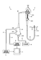
- FIG. 1 is a diagram schematically showing an ultrasonic endoscope system according to Embodiment 1 of the present invention.
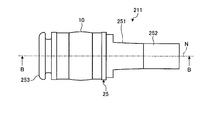
- FIG. 2 is a side view schematically showing the distal end configuration of the insertion portion of the ultrasonic endoscope according to the first embodiment of the present invention.
- FIG. 3 is a perspective view schematically showing the distal end configuration of the insertion portion of the ultrasonic endoscope according to the first embodiment of the present invention.
- 4 is a cross-sectional view taken along line AA shown in FIG. 5 is a cross-sectional view taken along line BB shown in FIG.
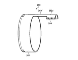
- FIG. 6 is a schematic diagram for explaining the configuration of the flexible substrate included in the ultrasonic endoscope according to the first embodiment of the present invention.
- FIG. 1 is a diagram schematically showing an ultrasonic endoscope system according to Embodiment 1 of the present invention.
- FIG. 2 is a side view schematically showing the distal end configuration of the insertion portion of the ultrasonic endoscope according to the first
- FIG. 7 is a development view of the flexible substrate shown in FIG.
- FIG. 8 is a cross-sectional view schematically showing the distal end configuration of the insertion portion of the ultrasonic endoscope according to the second embodiment of the present invention.
- FIG. 9 is a schematic diagram illustrating a configuration of a flexible substrate included in the ultrasonic endoscope according to the second embodiment of the present invention.
- FIG. 10 is a development view of the flexible substrate shown in FIG.
- FIG. 11 is a schematic diagram illustrating a configuration of a flexible substrate included in the ultrasonic endoscope according to the first modification of the second embodiment of the present invention.
- FIG. 12 is a schematic diagram illustrating a configuration of a flexible substrate included in the ultrasonic endoscope according to the second modification of the second embodiment of the present invention.
- FIG. 13 is a development view of the flexible substrate shown in FIG.
- FIG. 14 is a schematic diagram illustrating a configuration of a flexible substrate included in the ultrasonic endoscope according to the third embodiment of the present invention.
- FIG. 15 is a plan view in the direction of arrow C in FIG.
- FIG. 16 is a schematic diagram illustrating a configuration of a flexible substrate included in the ultrasonic endoscope according to the fourth embodiment of the present invention.
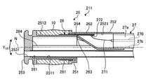
- FIG. 17 is a cross-sectional view schematically showing the distal end configuration of the insertion portion of the ultrasonic endoscope according to the fifth embodiment of the present invention.
- FIG. 18 is a schematic diagram for explaining a connection mode between a cable and a flexible board included in the ultrasonic endoscope according to the fifth embodiment of the present invention.
- FIG. 19 is a schematic diagram for explaining another example of the configuration of the flexible substrate included in the ultrasonic endoscope according to the embodiment of the present invention.
- FIG. 1 is a diagram schematically showing an ultrasonic endoscope system according to Embodiment 1 of the present invention.
- the endoscope system 1 is a system that performs ultrasonic diagnosis in a subject such as a person using an ultrasonic endoscope.
- the ultrasonic endoscope system 1 includes an ultrasonic endoscope 2, an ultrasonic observation device 3, an endoscope observation device 4, a display device 5, and a light source device 6. Prepare.
- the ultrasonic endoscope 2 is a combination of an observation optical system composed of a lens or the like and an endoscope observation unit having an imaging element and an ultrasonic probe, and has an endoscope observation function and an ultrasonic observation function. .
- the ultrasonic endoscope 2 converts an electrical pulse signal transmitted from the ultrasonic observation device 3 into an ultrasonic pulse (acoustic pulse) at the tip of the ultrasonic endoscope 2 and irradiates the subject, and is reflected by the subject.
- an ultrasonic transducer that converts the ultrasonic echo into an electrical echo signal expressed by a voltage change and outputs the electrical echo signal. The configuration of the ultrasonic transducer will be described later.
- the ultrasonic endoscope 2 includes an imaging optical system and an imaging element, and is inserted into a subject's digestive tract (esophagus, stomach, duodenum, large intestine) or respiratory organ (trachea, bronchus). Respiratory imaging can be performed.
- surrounding organs pancreas, gallbladder, bile duct, pancreatic duct, lymph node, organ in the mediastinum, blood vessels, etc.
- the ultrasonic endoscope 2 has a light guide that guides illumination light to be irradiated onto a subject during optical imaging.
- the light guide has a distal end reaching the distal end of the insertion portion of the ultrasonic endoscope 2 into the subject, and a proximal end portion connected to the light source device 6 that generates illumination light.
- the ultrasonic endoscope 2 includes an insertion unit 21, an operation unit 22, a universal cord 23, and a connector 24.
- the insertion part 21 is a part inserted into the subject.
- the insertion portion 21 includes a distal end hard portion 211 having an ultrasonic transducer 10 provided on the distal end side, and a bending portion 212 that is connected to the proximal end side of the distal end hard portion 211 and can be bent. And a flexible tube portion 213 connected to the proximal end side of the bending portion 212 and having flexibility.
- a light guide that transmits illumination light supplied from the light source device 6 and a plurality of signal cables that transmit various signals are inserted into the insertion portion 21.
- a channel (a treatment instrument channel described later) that forms a treatment instrument insertion passage for inserting the treatment instrument is inserted.
- the tip configuration of the insertion portion 21 will be described later.
- the operation unit 22 is a part that is connected to the proximal end side of the insertion unit 21 and receives various operations from a doctor or the like. As shown in FIG. 1, the operation unit 22 includes a bending knob 221 for performing a bending operation on the bending unit 212 and a plurality of operation members 222 for performing various operations.
- the operation section 22 is formed with a treatment instrument insertion port 223 that communicates with the treatment instrument channel and allows the treatment instrument to be inserted into the treatment instrument insertion path.
- the universal cord 23 is a cable that extends from the operation unit 22 and includes a plurality of signal cables that transmit various signals and an optical fiber that transmits illumination light supplied from the light source device 6.
- the connector 24 is provided at the tip of the universal cord 23.
- the connector 24 includes first to third connector portions 241 to 243 to which the ultrasonic cable 31, the video cable 41, and the light source device 6 are connected.
- the ultrasonic observation apparatus 3 is electrically connected to the ultrasonic endoscope 2 via the ultrasonic cable 31 (see FIG. 1), and outputs a pulse signal to the ultrasonic endoscope 2 via the ultrasonic cable 31.
- a pulse signal is input from the ultrasonic endoscope 2.
- the ultrasonic observation device 3 performs a predetermined process on the echo signal to generate an ultrasonic image.
- the endoscope observation apparatus 4 is electrically connected to the ultrasonic endoscope 2 via a video cable 41 (see FIG. 1), and an image signal from the ultrasonic endoscope 2 is input via the video cable 41. Is done. Then, the endoscope observation apparatus 4 performs a predetermined process on the image signal to generate an endoscope image.
- the display device 5 is configured using liquid crystal, organic EL (Electro Luminescence), or the like, and an ultrasonic image generated by the ultrasonic observation device 3 or an endoscope image generated by the endoscope observation device 4. Etc. are displayed.
- the light source device 6 supplies illumination light to the ultrasonic endoscope 2 through the optical fiber cable 61.
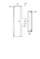
- FIG. 2 is a side view schematically showing the distal end configuration of the insertion portion of the ultrasonic endoscope according to the first embodiment of the present invention.
- FIG. 3 is a perspective view schematically showing the distal end configuration of the insertion portion of the ultrasonic endoscope according to the first embodiment of the present invention.
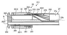
- 4 is a cross-sectional view taken along line AA in FIG. 5 is a cross-sectional view taken along line BB shown in FIG. 2 and 3 show the configuration of only the ultrasonic transducer 10 and the distal end hard portion 211 for explanation.
- the distal end hard portion 211 includes a hard member 25 formed using a hard material, a flexible substrate 26 provided at least partially inside the hard member 25, and the ultrasonic transducer 10 described above.
- the distal end hard portion 211 has an outer surface composed of the ultrasonic transducer 10 and the hard member 25 and has rigidity.
- the rigid member 25 includes a functional unit 251 that holds the ultrasonic transducer 10 on the side, and an ultrasonic wave that extends from the proximal end side of the functional unit 251 and is electrically connected to the ultrasonic transducer 10 via the flexible substrate 26. And a holding portion 252 that holds the cable 27.
- the rigid member 25 is formed with balloon locking portions that can lock one end and the other end of a balloon that can be filled with an ultrasonic medium on the distal end side and the proximal end side with respect to the ultrasonic transducer 10. ing.
- the function part 251 has a first hole part 2511, a part of the outer peripheral surface of the function part 251, a concave part 2512 to which the ultrasonic transducer 10 is attached, and a holding part that communicates with the first hole part 2511. Holes 2531 to 2534 are formed.
- the functional unit 251 communicates with the treatment instrument insertion passage formed in the insertion unit 21 to project the treatment tool from the distal end of the insertion unit 21 or to suck fluid such as liquid or gas in the subject.
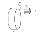
- a front-field optical unit that includes a treatment instrument channel 281, a light guide 282 that guides illumination light, one or a plurality of lenses, an image sensor, and the like, and receives observation light for generating a front-field image in the subject.
- the front visual field optical unit 283 corresponds to an imaging unit.
- the rigid member 25 has a holding hole 2531 for holding the end of the treatment instrument channel 281, a holding hole 2532 for holding the end of the light guide 282, and the front visual field optical part 283.
- a holding hole 2533 for holding the optical member to be held and a holding hole 2534 for holding the end portion of the air / water supply pipe 284 are formed.
- the treatment instrument channel 281, the light guide 282, the front visual field optical unit 283, and the air / water supply tube 284 are each held in a watertight manner in the holding holes 2531 to 2534.
- the treatment instrument channel 281 has an opening at the distal end in the longitudinal direction, and the opening communicates with the holding hole 2531.
- the holding part 252 is formed with a second hole part 2521 capable of holding the ultrasonic cable 27.
- the second hole portion 2521 has a hole shape that gradually increases in diameter from the distal end side toward the proximal end side and then extends with a uniform diameter.
- the maximum diameter among the outer diameters of the holding part 252 is smaller than the diameter of the first hole part 2511 of the functional part 251.
- the concave portion 2512 of the functional portion 251 and the second hole portion 2521 of the holding portion 252 communicate with each other via the communication portion 254.
- the ultrasonic transducer 10 irradiates ultrasonic waves in a direction perpendicular to the longitudinal direction around the axis parallel to the longitudinal direction of the insertion portion 21 (for example, the central axis N direction of the rigid member 211).
- the radial vibrator that scans the The ultrasonic transducer 10 is electronically scanned by arranging a plurality of piezoelectric elements along the circumferential direction and electronically switching the piezoelectric elements involved in transmission / reception or delaying transmission / reception of each piezoelectric element. Let The ultrasonic transducer 10 irradiates the observation target with ultrasonic waves when the piezoelectric element vibrates by the input of the pulse signal.
- ultrasonic waves reflected from the observation target are transmitted to the piezoelectric element.
- the piezoelectric element is vibrated by the transmitted ultrasonic wave, the piezoelectric element converts the vibration into an electrical signal, and is output as an echo signal to the ultrasonic observation apparatus 3 via the flexible substrate 26, the ultrasonic cable 27, and the like. To do.
- the ultrasonic transducer 10 sequentially vibrates each piezoelectric element, sequentially irradiates ultrasonic waves in the circumferential direction, and receives ultrasonic echoes reflected from the observation target. That is, the ultrasonic transducer 10 receives an ultrasonic echo that forms a cross-sectional image of an annular scanning surface around the ultrasonic transducer 10. Further, the ultrasonic transducer 10 has an outer surface in which the central portion of the ultrasonic transducer 10 along the longitudinal direction of the insertion portion 21 is in a direction perpendicular to the longitudinal direction as compared to both end portions of the longitudinal direction. It protrudes. In the ultrasonic transducer 10, for example, an acoustic lens forms the outer surface.
- the acoustic lens has a function of converging an ultrasonic wave in a convex shape toward the center, and emits an ultrasonic wave transmitted from the piezoelectric element to the outside or takes in an ultrasonic echo from the outside.
- the acoustic lens of the ultrasonic transducer 10 is described as having a convex shape in the case of using a material whose sound velocity is slower than that of the observation target, such as silicone.
- a concave acoustic lens material it is possible to use a concave acoustic lens material.
- the ultrasonic transducer 10 is connected to the flexible substrate 26.
- One end side of the flexible substrate 26 in the central axis N direction is connected to the ultrasonic transducer 10, and the other end side enters the second hole portion 2521 of the holding portion 252 through the communication portion 254.
- an electrode connected to each piezoelectric element of the ultrasonic transducer 10 and a wiring pattern formed on the flexible substrate 26 are fixed by a conductive fixing member such as solder.
- the flexible substrate 26 is connected to the ultrasonic cable 27 in the second hole portion 2521.
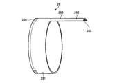
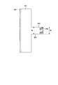
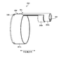
- FIG. 6 is a schematic diagram for explaining the configuration of the flexible substrate provided in the ultrasonic endoscope according to the first embodiment of the present invention.
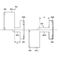
- FIG. 7 is a development view of the flexible substrate shown in FIG.
- the flexible substrate 26 includes a first connection portion 261 connected to the ultrasonic transducer 10, a second connection portion 262 connected to each core wire 271 of the ultrasonic cable 27, and a first connection portion 261.
- the connection part 263 which connects the center part of the circumferential direction of this and the 2nd connection part 262 is provided.
- the first connection portion 261 is curved so that the same main surface faces each other, and has a ring shape in which a part in the circumferential direction is cut.
- electrodes a plurality of electrodes 264 in FIG. 7 connected to the respective electrodes of the ultrasonic transducer 10 are formed along the circumferential direction.
- the main surface here refers to the surface having the largest area.
- the second connection part 262 is curved on the same side as the first connection part 261.
- Each of the second connection portions 262 is an electrode connected to one of the electrodes (electrodes 264) formed on the first connection portion 262 by a wiring pattern (not shown), and the core wire of the ultrasonic cable 27 (see FIG. 5 (electrode 265 in FIG. 7) connected to the core wire 271) shown in FIG.
- the connecting portion 263 passes the above-described wiring pattern.
- the connecting portion 263 penetrates the communicating portion 254 in a state where the connecting portion 263 is disposed on the rigid member 25 (see FIG. 5).
- the width of the second connection portion 262 (width w 1 in FIG. 7) and the width of the connection portion 263 (width w 2 in FIG. 7) are: The same.
- the ultrasonic cable 27 is configured by covering a plurality of coaxial wires 270 provided according to the number of piezoelectric elements to be connected with an insulating jacket 27a.
- the jacket 27a covers a plurality of coaxial wires 270 collected in a bundle.
- a comprehensive shield 27b is provided on the inner periphery of the jacket 27a.
- a circle indicated by a broken line in FIG. 4 indicates the outer diameter of the jacket 27a.
- the coaxial wire 270 includes a conductive core wire (core wire 271), a dielectric layer (not shown) that covers the core wire 271, a shield (not shown) that covers the dielectric layer, and an insulating material that covers the shield. It consists of a protective film (not shown).
- FIG. 5 shows an example in which only one core wire 271 extends and is connected to the flexible substrate 26 by solder 272 for the sake of explanation, but in reality, the number of core wires (coaxial wire 270) is equal to the number of piezoelectric elements to be connected. Exists.
- the ultrasonic cable 27 is held by the holding portion 252 in a state where the jacket 27 a is inserted from the proximal end side of the holding portion 252. At this time, the jacket 27a is press-fitted into the holding portion 252 or fixed to the second hole 2521 of the holding portion 252 with an adhesive or the like.
- Each coaxial wire 270 is inserted into the insertion portion 21 in a state of being covered with the jacket 270 up to the holding portion 252, and the core wire 271 is exposed in the second hole portion 2521 of the holding portion 252.
- each coaxial line 270 is covered with the jacket 27a while being fixed from the flexible tube portion 213 through the bending portion 212 to the proximal end side of the distal end hard portion 211, and is fixed to the holding portion 252 while ensuring insulation. ing.
- the holding unit 252 is located near the outer periphery of the functional unit 251.
- the ultrasonic cable 27 held by the holding unit 252 is also located near the outer periphery of the functional unit 251. That is, in the first embodiment, the ultrasonic cable 27 is located near the outer periphery of the rigid member 25 in the radial direction orthogonal to the central axis N direction (see FIG. 4).
- the straight line L passing through the central axis N and orthogonal to the central axis N in the cross section passing through the end of the jacket 27 a in the distal end hard portion 211 is the center of the ultrasonic cable 27. And the center of the channel 281.
- the ultrasonic cable 27 and the channel 281 have a larger outer diameter than other contents. For this reason, the ultrasonic cable 27 and the channel 281 are disposed along the straight line L that passes through the central axis N and is orthogonal to the central axis N, thereby minimizing the diameter of the distal end hard portion 211. be able to.
- the straight line L is a bending direction of the bending portion 212, by a parallel to the curve direction Y UD corresponding to the vertical direction of the image to be imaged (see FIGS. 4 and 5), the Y UD direction when the curved, it is possible to suppress the vibration in the lateral direction Y LR orthogonal to the bending direction Y UD.
- the ultrasonic cable 27 formed by covering the plurality of coaxial wires 270 with the insulating jacket 27a is connected to the insulating hard member 25 positioned at the tip of the bending portion 212, In this rigid member 25, the core wire 271 is exposed and connected to the flexible substrate 26.
- the ultrasonic cable 27 is inserted into the bending portion 212 in a state where a plurality of coaxial lines are bundled by the jacket 27a and the comprehensive shield 27b disposed inside the jacket 27a, the coaxial line It is possible to reduce noise superimposed on and noise radiated from the coaxial line.
- the ultrasonic cable 27 in which a plurality of coaxial wires 270 are bundled passes through the bending portion 212, the area occupied by the ultrasonic cable 27 in the insertion portion 21 is smaller than that in the case of using a flexible substrate. Thus, the increase in diameter can be suppressed.
- the front visual field optical unit 283, and the channel 281 noise can be reduced and the increase in diameter of the insertion unit can be suppressed.
- the conventional configuration in which the coaxial line is connected to the flexible substrate on the proximal end side of the curved portion and the flexible substrate is inserted through the curved portion is easily affected by noise and is resistant to noise. It is difficult to reduce the diameter of the flexible substrate because it is necessary to increase the thickness of the flexible substrate.
- the ultrasonic cable 27 is secured to the rigid member 25 while ensuring insulation. Can be easily connected.
- the ultrasonic cable 27 is arranged in the bending portion 212 in a state where the coaxial line 270 is covered with the jacket 27a, the coaxial line is hardly broken.
- the jacket 27a covering the plurality of coaxial wires 270 and the holding portion 252 holding the jacket 27a ultrasonic waves with high electrical safety are provided. It can be an endoscope.
- FIG. 8 is a cross-sectional view schematically showing the distal end configuration of the insertion portion of the ultrasonic endoscope according to the second embodiment of the present invention.
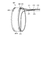
- FIG. 9 is a schematic diagram illustrating a configuration of a flexible substrate included in the ultrasonic endoscope according to the second embodiment of the present invention.
- FIG. 10 is a development view of the flexible substrate shown in FIG.
- the distal end hard portion 211 of the ultrasonic endoscope 2 according to the second embodiment includes a flexible substrate 26A instead of the flexible substrate 26 in the configuration diagram of the first embodiment described above.
- the configuration is the same as that of the first embodiment described above except that the flexible substrate is changed.
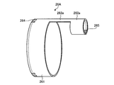
- the flexible substrate 26 ⁇ / b> A has an annular shape in which a part in the circumferential direction is cut, and has a first connection part 261 connected to the ultrasonic transducer 10, an annular shape in which a part in the circumferential direction is cut, and each of the ultrasonic cables 27. It has the 2nd connection part 262a connected with the core wire 271, and the connection part 263a which connects the center parts of the circumferential direction of the 1st connection part 261 and the 2nd connection part 262a.
- Each of the second connecting portions 262a is an electrode connected to one of the electrodes formed on the first connecting portion 262 by a wiring pattern (not shown), and is a core wire of the ultrasonic cable 27 (the core wire shown in FIG. 8). 271) and electrodes (electrodes 265 in FIG. 10) are formed.
- the ground lines of the coaxial lines 270 are not shown, the ground lines are gathered together in the vicinity of the end portion of the jacket 27a on the base end side, and the electrodes on the ground side (outer peripheral surface side) of the piezoelectric element are flexible. They are connected via a dedicated pattern provided on the board 26A, or are connected via a connection cable provided separately.
- the wiring pattern described above passes through the connecting portion 263a.
- the connecting portion 263 a penetrates the communicating portion 254 in a state where it is disposed on the rigid member 25.
- the width of the first connecting portion 261 (width w 3 in FIG. 10), the width of the second connecting portion 262a (width w 4 in FIG. 10), and the width of the connecting portion 263a (in FIG. 10).
- the width w 5 has a relationship of w 5 ⁇ w 3 and w 5 ⁇ w 4 .
- the width of the first connecting portion 261 (width w 3 in FIG. 10), the width of the second connecting portion 262a (width w 4 in FIG. 10), and the width of the connecting portion 263a (
- the ultrasonic transducer 10 and the ultrasonic cable 27 are electrically connected by using a flexible substrate 26A having a relationship of w 5 ⁇ w 4 ⁇ w 3 with the width w 5 ) in FIG.
- a flexible substrate 26A having a relationship of w 5 ⁇ w 4 ⁇ w 3 with the width w 5
- interference between the adjacent core wires 271 can be more reliably suppressed, and workability when the core wire 271 is connected to the electrode 265 during manufacturing can be improved.
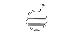
- the second connection portion 262a connected to each core wire 271 of the ultrasonic cable 27 does not have to be annular, and can be spiral or folded.
- the second connecting portion 262a and the spiral it is possible to increase the width w 4 capable of performing a connection with the cable.
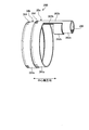
- FIG. 11 is a schematic diagram illustrating a configuration of a flexible substrate included in the ultrasonic endoscope according to the first modification of the second embodiment of the present invention.
- the flexible substrate 26B according to the first modification is formed by overlapping a part of two flexible substrates (first flexible substrate 26a and second flexible substrate 26b).
- the first flexible substrate 26a has an annular shape with a part cut in the circumferential direction, the first connecting portion 261a connected to the ultrasonic transducer 10, the annular shape with a part cut in the circumferential direction, and the ultrasonic cable 27.
- a second connecting portion 262b connected to each of the core wires 271 and a connecting portion 263b connecting the circumferential central portions of the first connecting portion 261a and the second connecting portion 262b.
- the second flexible substrate 26b has the same configuration as the first flexible substrate 26a.
- the second flexible substrate 26b includes a first connection part 261a, a second connection part 262b, and a connection part 263b.
- electrodes 264 connected to the respective electrodes of the ultrasonic transducer 10 are formed along the circumferential direction.
- a plurality of electrodes 264 that are respectively connected to the piezoelectric elements of the ultrasonic transducer 10 are formed on the first connection portions 261a of the first flexible substrate 26a and the second flexible substrate 26b.
- Each of the second connection portions 262b of the first flexible substrate 26a and the second flexible substrate 26b is an electrode that is connected to one of the electrodes formed on the first connection portion 262a by a wiring pattern (not shown). Electrodes 265 connected to the core wire of the ultrasonic cable 27 (core wire 271 shown in FIG. 8) are respectively formed.
- all the electrodes 264 formed in the first connection portion 261 according to the second embodiment are arranged separately in the first connection portions 261a of the first flexible substrate 26a and the second flexible substrate 26b. Is done.
- all the electrodes 264 formed on the second connection portion 262a according to the second embodiment are arranged separately on the second connection portions 261b of the first flexible substrate 26a and the second flexible substrate 26b. For this reason, the number of electrodes 264 and 265 formed on each first connection portion 261a and each second connection portion 262b is formed on the first connection portion 261 and the second connection portion 262a according to Embodiment 2 described above. It can be about half of the number of electrodes.
- the wiring pattern described above passes through the connecting portion 263b.
- the width of the first connecting portion 261a, the width of the second connecting portion 262b, and the width of the connecting portion 263b are the same as the width relationship (w 5 ⁇ w 4 ⁇ w 3 ) of the second embodiment described above. Have a relationship.
- the first flexible substrate 26a and the second flexible substrate 26b are hard because the first connection portion 261a and the second connection portion 262b are adjacent to each other in the central axis N direction, and a part of the connection portions 263c and 263d overlap each other. It is disposed on the member 25.
- the overlapping connecting portion 263b passes through the communication portion 254.
- the flexible substrate 26B formed by overlapping the first flexible substrate 26a and the second flexible substrate 26b is formed.
- the number of the electrodes 264 and 265 formed in one first connection portion 261a and second connection portion 262b can be halved.
- the wiring density of the wiring patterns formed on the first flexible substrate 26a and the second flexible substrate 26b can be reduced, and it is possible to cope with the increase in the number of elements.
- connection part 263b since the connection part 263b is piled up and the communication part 254 is penetrated, it arrange
- the second connecting portions 262b of the first flexible substrate 26a and the second flexible substrate 26b are described as being adjacent to each other in the central axis N direction, but may be partially overlapped.
- FIG. 12 is a schematic diagram illustrating a configuration of a flexible substrate included in the ultrasonic endoscope according to the second modification of the second embodiment of the present invention.
- FIG. 13 is a development view of the flexible substrate shown in FIG.
- the flexible substrate 26C according to the second modification is formed by overlapping a part of two flexible substrates (a first flexible substrate 26c and a second flexible substrate 26d).
- the first flexible substrate 26c extends in an arc shape, forms a first connection portion 261b that connects to the ultrasonic transducer 10, and a ring that is partially cut in the circumferential direction, and is connected to each core wire 271 of the ultrasonic cable 27.
- the second connection part 262b, and a connecting part 263c that connects one end in the circumferential direction of the first connection part 261b and the central part in the circumferential direction of the second connection part 262b.
- the wiring pattern described above passes through the connecting portion 263c.
- the connecting portion 263 c penetrates the communicating portion 254 in a state where it is disposed on the rigid member 25.
- the second flexible substrate 26d extends in an arc shape that curves in a direction opposite to the first connection portion 261b, and has a first connection portion 261c that is connected to the ultrasonic transducer 10 and an annular shape that is partially cut off in the circumferential direction. None, a second connecting portion 262b connected to each core wire 271 of the ultrasonic cable 27, a connecting portion 263d connecting one end in the circumferential direction of the first connecting portion 261c and a central portion in the circumferential direction of the second connecting portion 262b, Have.
- the wiring pattern described above passes through the connecting portion 263d.
- the connecting portion 263 c penetrates the communicating portion 254 in a state where it is disposed on the rigid member 25.
- the second flexible substrate 26 d, the length d 2 between the first connecting portion 261c and the second connecting portion 262b by connecting the connecting portion 263d is in the first flexible substrate 26c, the first connection by connecting the connecting portion 263c It is larger than the length d 1 between the part 261b and the second connection part 262b.
- the first flexible substrate 26c and the second flexible substrate 26d are disposed on the rigid member 25 such that the second connection portions 262b are adjacent to each other and a part of the connection portion 263b overlaps. Overlapping connecting portions 263c and 263d pass through the communication portion 254. At this time, the first connection portions 261 b and 261 c extend in an arc shape on the opposite sides to form an intermittent cylinder having an inner diameter along the surface of the recess 2512.
- the wiring density of the wiring pattern can be reduced, and it is possible to cope with the increase in the number of elements.
- the piezoelectric element and the two flexible substrates 26c and 26d can be connected at the base end side end portion of the piezoelectric element, and the connection between the piezoelectric element and the flexible substrate is easier. It becomes.
- the width of the second connection portion 262b is increased from the first connection portion 261b, so that the pitch of the electrodes 265 to be connected to the cable is set as described in the second embodiment. Therefore, the positioning of the flexible board and the cable is facilitated, and the wiring work is facilitated.
- FIG. 14 is a schematic diagram illustrating a configuration of a flexible substrate included in the ultrasonic endoscope according to the third embodiment of the present invention.
- FIG. 15 is a plan view in the direction of arrow C in FIG. 14 and is a plan view showing the configuration of the second connection portion 262D.
- the distal end hard portion 211 of the ultrasonic endoscope 2 according to the third embodiment includes a flexible substrate 26D instead of the flexible substrate 26 having the configuration of the first embodiment described above (see FIG. 2).
- the configuration is the same as that of the first embodiment described above except that the flexible substrate is changed.
- the flexible substrate 26 ⁇ / b> D has an annular shape with a part cut in the circumferential direction, and has a first connection part 261 connected to the ultrasonic transducer 10, an annular shape with a part cut in the circumferential direction, and each of the ultrasonic cables 27. It has the 2nd connection part 262c connected with the core wire 271, and the connection part 263e which connects the 1st connection part 261 and the 2nd connection part 262c.
- the second connection part 262c has a zigzag shape in which the extending direction is reversed along the longitudinal direction.
- Each of the second connection portions 262c is an electrode connected to any one of the electrodes formed on the first connection portion 261 by a wiring pattern (not shown), and is connected to the core wire 271 of the ultrasonic cable 27 ( For example, electrodes 265) are formed respectively.
- the circle circumscribing the second connection portion 262 c is smaller than the inner diameter of the second hole portion 2521.
- the longitudinal direction of the band-shaped constituent part constituting the second connecting part 262c is orthogonal to the above-described central axis N direction.
- the second connecting portion 262c may be formed by using a zigzag band-shaped component along the longitudinal direction parallel to the central axis N direction described above.
- the wiring pattern described above passes through the connecting portion 263e.
- the connecting portion 263 e penetrates the communicating portion 254 in a state where it is disposed on the rigid member 25.
- the ultrasonic transducer 10 and the ultrasonic cable 27 are electrically connected using the flexible substrate 26D having the second connection portion 262c having a zigzag shape.
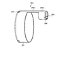
- FIG. 16 is a schematic diagram illustrating a configuration of a flexible substrate included in the ultrasonic endoscope according to the fourth embodiment of the present invention.
- the distal end hard portion 211 of the ultrasonic endoscope 2 according to the fourth embodiment includes a flexible substrate 26E instead of the flexible substrate 26 having the configuration of the first embodiment described above (see FIG. 2).
- the configuration is the same as that of the first embodiment described above except that the flexible substrate is changed.
- the flexible substrate 26 ⁇ / b> E has an annular shape in which a part in the circumferential direction is cut, and has a first connection part 261 connected to the ultrasonic transducer 10, an annular shape in which a part in the circumferential direction is cut, and each of the ultrasonic cables 27. It has the 2nd connection part 262d connected with the core wire 271, and the connection part 263f which connects the center parts of the circumferential direction of the 1st connection part 261 and the 2nd connection part 262d.
- Each of the second connection portions 262d is an electrode connected to one of the electrodes formed on the first connection portion 262 with a wiring pattern (not shown), and is connected to the core wire 271 of the ultrasonic cable 27. Are formed respectively.
- the electrode 265 is formed on the same side as the side on which the electrode 264 of the first connection portion 261 is formed, and the longitudinal direction is parallel to the width direction. Each electrode 265 is formed along the direction perpendicular to the width direction on the surface of the second connection portion 262d. Further, the second connection portion 262d has a width larger than that of the connecting portion 263f.
- the wiring pattern described above passes through the connecting portion 263f.
- the connecting portion 263 f penetrates the communicating portion 254 in a state where the connecting portion 263 f is disposed on the rigid member 25.
- each electrode 265 is formed along the direction perpendicular to the width direction on the surface of the second connection portion 262d. Even in such a configuration, it is possible to reduce the wiring density of the wiring pattern as described above, and it is possible to cope with the increase in the number of elements.
- the electrode 265 has been described as having the longitudinal direction parallel to the width direction.
- the longitudinal direction may be parallel to the width direction
- the longitudinal direction may be parallel to the width direction.
- And may be inclined (for example, making an acute angle).
- FIG. 17 is a cross-sectional view schematically showing the distal end configuration of the insertion portion of the ultrasonic endoscope according to the fifth embodiment of the present invention.
- FIG. 18 is a schematic diagram for explaining a connection mode between a cable and a flexible board included in the ultrasonic endoscope according to the fifth embodiment of the present invention.
- the distal end hard portion 211 of the ultrasonic endoscope 2 according to the fifth embodiment includes a flexible substrate 26F instead of the flexible substrate 26 in the configuration diagram of the first embodiment described above.
- the connecting portion that connects the first connecting portion and the second connecting portion in the flexible substrate has been described as passing through the communicating portion. Part of the through hole penetrates the communication part 254.
- the flexible substrate 26F has an annular shape with a part cut in the circumferential direction, and includes a main body portion 261d connected to the ultrasonic transducer 10 at one end side and connected to each core wire 271 of the ultrasonic cable 27 at the other end side.
- the main body 261d has an annular shape in which a part in the circumferential direction is cut.
- electrodes 264 connected to the respective electrodes of the ultrasonic transducer 10 are formed along the circumferential direction, and each of the electrodes formed on the first connection portion 261 by a wiring pattern (not shown).
- An electrode 265 that is connected to any one of the electrodes 265 and connected to the core wire 271 of the ultrasonic cable 27 is formed along the circumferential direction.
- the coaxial wire 270 extends from the second hole portion 2521 to the communication portion 254 in a state where the core wire 271 is covered with the protective film 274 and passes through the communication portion 254, so that the shield 273 is exposed.
- Each coaxial wire 270 circulates along the flexible substrate 26 ⁇ / b> F with the core wire 271 (or insulating layer) exposed in the recess 2512, and is connected to the connection target electrode 265 by the solder 272.
- the electrode 265 is inclined with respect to the central axis N as it is away from the communication portion 254. That is, the longitudinal direction of the connection surface of the electrode 265 is inclined along the direction in which the core wire 271 of the coaxial line 270 to be connected enters.
- the coaxial wire 270 passes through the communication portion 254, and the electrode 265 inclined along the direction in which the core wire 271 enters and the core wire 271 are connected. Even in such a configuration, it is possible to reduce the wiring density of the wiring pattern as described above, and it is possible to cope with the increase in the number of elements. Further, since the longitudinal direction of the electrode 265 is aligned with the core wire 271, the stress applied to the core wire 271 connected to the electrode 265 can be reduced.
- the coaxial line 270 and the piezoelectric element may be directly connected without using the flexible substrate 26F.
- the electrode 265 is described as having the longitudinal direction parallel to the width direction.
- the longitudinal direction may be parallel to the width direction, or the longitudinal direction may be parallel to the width direction. And may be inclined (for example, inclined so that the longitudinal direction and the width direction form an acute angle).
- the electrodes 264 and 265 are provided on one surface of the flexible substrate.
- the electrode formation surface may be the opposite surface, for example, As shown in the flexible substrate 26G shown in FIG. 19, the electrodes 265 may be formed on both surfaces.
- the plurality of electrodes are arranged in a line along the circumferential direction
- these electrodes may be arranged in a plurality of lines along the circumferential direction.
- the ultrasonic endoscope according to the present invention has a configuration including a radial ultrasonic transducer, a front-view optical system, and a channel, which reduces noise and has a large diameter insertion portion. It is useful for suppressing crystallization.
Landscapes
- Health & Medical Sciences (AREA)
- Life Sciences & Earth Sciences (AREA)
- Engineering & Computer Science (AREA)
- Medical Informatics (AREA)
- Surgery (AREA)
- Pathology (AREA)
- Radiology & Medical Imaging (AREA)
- Biophysics (AREA)
- Biomedical Technology (AREA)
- Heart & Thoracic Surgery (AREA)
- Physics & Mathematics (AREA)
- Molecular Biology (AREA)
- Nuclear Medicine, Radiotherapy & Molecular Imaging (AREA)
- Animal Behavior & Ethology (AREA)
- General Health & Medical Sciences (AREA)
- Public Health (AREA)
- Veterinary Medicine (AREA)
- Mechanical Engineering (AREA)
- Gynecology & Obstetrics (AREA)
- Ultra Sonic Daignosis Equipment (AREA)
Abstract
Cet endoscope à ultrasons est pourvu des éléments suivants : une partie d'insertion ayant une partie de pointe dure, une partie incurvée, et un tube flexible ; un transducteur ultrasonore radial ; une unité d'imagerie qui capture des images d'un champ visuel à l'avant de la partie d'insertion dans la direction longitudinale ; un canal dont une extrémité a une ouverture au niveau de la pointe de direction longitudinale de la partie de pointe dure ; une pluralité de lignes coaxiales qui sont électriquement connectées à une pluralité d'éléments piézoélectriques, respectivement ; et un câble à ultrasons ayant un blindage composite métallique qui recouvre la pluralité de lignes coaxiales, et une chemise isolante qui recouvre le blindage composite, la chemise s'étendant de la partie de tube flexible, au-delà de la partie incurvée, et à l'extrémité de base de la partie de pointe dure dans un état de recouvrement de la pluralité de lignes coaxiales, et étant fixée à l'extrémité de base de la partie de pointe dure et à proximité du côté circonférentiel externe de celle-ci.
Priority Applications (2)
| Application Number | Priority Date | Filing Date | Title |
|---|---|---|---|
| CN201880023883.4A CN110494084B (zh) | 2017-04-03 | 2018-04-03 | 超声波内窥镜 |
| US16/591,709 US20200037989A1 (en) | 2017-04-03 | 2019-10-03 | Ultrasound endoscope |
Applications Claiming Priority (2)
| Application Number | Priority Date | Filing Date | Title |
|---|---|---|---|
| JP2017073879A JP6791799B2 (ja) | 2017-04-03 | 2017-04-03 | 超音波内視鏡 |
| JP2017-073879 | 2017-04-03 |
Related Child Applications (1)
| Application Number | Title | Priority Date | Filing Date |
|---|---|---|---|
| US16/591,709 Continuation US20200037989A1 (en) | 2017-04-03 | 2019-10-03 | Ultrasound endoscope |
Publications (1)
| Publication Number | Publication Date |
|---|---|
| WO2018186422A1 true WO2018186422A1 (fr) | 2018-10-11 |
Family
ID=63713092
Family Applications (1)
| Application Number | Title | Priority Date | Filing Date |
|---|---|---|---|
| PCT/JP2018/014328 WO2018186422A1 (fr) | 2017-04-03 | 2018-04-03 | Endoscope à ultrasons |
Country Status (4)
| Country | Link |
|---|---|
| US (1) | US20200037989A1 (fr) |
| JP (1) | JP6791799B2 (fr) |
| CN (1) | CN110494084B (fr) |
| WO (1) | WO2018186422A1 (fr) |
Families Citing this family (1)
| Publication number | Priority date | Publication date | Assignee | Title |
|---|---|---|---|---|
| CN110809432B (zh) * | 2017-06-29 | 2023-07-25 | 泰尔茂株式会社 | 图像诊断用导管 |
Citations (6)
| Publication number | Priority date | Publication date | Assignee | Title |
|---|---|---|---|---|
| JPH0542146A (ja) * | 1991-08-14 | 1993-02-23 | Olympus Optical Co Ltd | 超音波プローブ |
| JP2000245734A (ja) * | 1999-03-01 | 2000-09-12 | Olympus Optical Co Ltd | 超音波内視鏡診断装置 |
| JP2002153469A (ja) * | 2000-11-21 | 2002-05-28 | Asahi Optical Co Ltd | 超音波内視鏡 |
| JP2004298240A (ja) * | 2003-03-28 | 2004-10-28 | Olympus Corp | 超音波内視鏡 |
| JP2006034743A (ja) * | 2004-07-29 | 2006-02-09 | Fujinon Corp | 超音波内視鏡 |
| JP2008237842A (ja) * | 2007-03-29 | 2008-10-09 | Fujinon Corp | 超音波内視鏡 |
Family Cites Families (9)
| Publication number | Priority date | Publication date | Assignee | Title |
|---|---|---|---|---|
| JP3009722B2 (ja) * | 1990-10-16 | 2000-02-14 | 日本電波工業株式会社 | 超音波探触子 |
| JP2847575B2 (ja) * | 1990-10-30 | 1999-01-20 | 日本電波工業株式会社 | 超音波深触子 |
| JP3619424B2 (ja) * | 2000-05-10 | 2005-02-09 | ペンタックス株式会社 | ラジアル走査前方視型超音波内視鏡 |
| US6468221B2 (en) * | 2000-11-21 | 2002-10-22 | Asahi Kogaku Kogyo Kabushiki Kaisha | Ultrasonic endoscope |
| US6582371B2 (en) * | 2001-07-31 | 2003-06-24 | Koninklijke Philips Electronics N.V. | Ultrasound probe wiring method and apparatus |
| JP2008099036A (ja) * | 2006-10-12 | 2008-04-24 | Olympus Medical Systems Corp | 超音波トランスデューサ、超音波探触子及び超音波診断装置 |
| US9788813B2 (en) * | 2010-10-13 | 2017-10-17 | Maui Imaging, Inc. | Multiple aperture probe internal apparatus and cable assemblies |
| WO2012132883A1 (fr) * | 2011-03-25 | 2012-10-04 | オリンパスメディカルシステムズ株式会社 | Endoscope |
| JP6242126B2 (ja) * | 2013-09-04 | 2017-12-06 | オリンパス株式会社 | 内視鏡 |
-
2017
- 2017-04-03 JP JP2017073879A patent/JP6791799B2/ja active Active
-
2018
- 2018-04-03 CN CN201880023883.4A patent/CN110494084B/zh active Active
- 2018-04-03 WO PCT/JP2018/014328 patent/WO2018186422A1/fr active Application Filing
-
2019
- 2019-10-03 US US16/591,709 patent/US20200037989A1/en not_active Abandoned
Patent Citations (6)
| Publication number | Priority date | Publication date | Assignee | Title |
|---|---|---|---|---|
| JPH0542146A (ja) * | 1991-08-14 | 1993-02-23 | Olympus Optical Co Ltd | 超音波プローブ |
| JP2000245734A (ja) * | 1999-03-01 | 2000-09-12 | Olympus Optical Co Ltd | 超音波内視鏡診断装置 |
| JP2002153469A (ja) * | 2000-11-21 | 2002-05-28 | Asahi Optical Co Ltd | 超音波内視鏡 |
| JP2004298240A (ja) * | 2003-03-28 | 2004-10-28 | Olympus Corp | 超音波内視鏡 |
| JP2006034743A (ja) * | 2004-07-29 | 2006-02-09 | Fujinon Corp | 超音波内視鏡 |
| JP2008237842A (ja) * | 2007-03-29 | 2008-10-09 | Fujinon Corp | 超音波内視鏡 |
Also Published As
| Publication number | Publication date |
|---|---|
| JP2018174983A (ja) | 2018-11-15 |
| CN110494084A (zh) | 2019-11-22 |
| CN110494084B (zh) | 2022-05-27 |
| US20200037989A1 (en) | 2020-02-06 |
| JP6791799B2 (ja) | 2020-11-25 |
Similar Documents
| Publication | Publication Date | Title |
|---|---|---|
| CN109152567B (zh) | 超声波内窥镜 | |
| JP6741637B2 (ja) | 超音波内視鏡 | |
| JP2022044905A (ja) | 超音波気管支鏡 | |
| WO2018186422A1 (fr) | Endoscope à ultrasons | |
| JP6133001B1 (ja) | 超音波振動子モジュールおよび超音波内視鏡 | |
| JPWO2016009689A1 (ja) | 超音波内視鏡 | |
| JP2006280407A (ja) | 超音波内視鏡 | |
| US20190117188A1 (en) | Ultrasonic transducer module, ultrasonic endoscope and processing method of ultrasonic transducer module | |
| CN107708573B (zh) | 超声波内窥镜 | |
| JP6697962B2 (ja) | 超音波振動子および超音波内視鏡 | |
| WO2022074776A1 (fr) | Unité de connexion de câblage de transmission de signal, endoscope, procédé de fabrication d'unité de connexion de câblage de transmission de signal, et module oscillateur à ultrasons | |
| JP7324181B2 (ja) | 超音波内視鏡 | |
| WO2019039384A1 (fr) | Endoscope à ultrasons | |
| JP7395277B2 (ja) | 信号伝送配線接続ユニット、内視鏡、信号伝送配線接続ユニットの製造方法および超音波振動子モジュール | |
| JP7324180B2 (ja) | 超音波内視鏡 | |
| JP6952533B2 (ja) | 超音波内視鏡 | |
| US11944496B2 (en) | Ultrasound endoscope | |
| JP2017074231A (ja) | 超音波内視鏡の製造方法および超音波内視鏡 | |
| JP6581302B2 (ja) | 超音波振動子モジュールおよび超音波内視鏡 | |
| WO2020202358A1 (fr) | Transducteur à ultrasons, endoscope à ultrason et procédé de fabrication d'un transducteur à ultrasons | |
| WO2017150461A1 (fr) | Unité de sonde à ultrasons, endoscope à ultrasons, et procédé de fabrication d'unité de sonde à ultrasons |
Legal Events
| Date | Code | Title | Description |
|---|---|---|---|
| 121 | Ep: the epo has been informed by wipo that ep was designated in this application |
Ref document number: 18781654 Country of ref document: EP Kind code of ref document: A1 |
|
| NENP | Non-entry into the national phase |
Ref country code: DE |
|
| 122 | Ep: pct application non-entry in european phase |
Ref document number: 18781654 Country of ref document: EP Kind code of ref document: A1 |