WO2018186422A1 - Ultrasound endoscope - Google Patents
Ultrasound endoscope Download PDFInfo
- Publication number
- WO2018186422A1 WO2018186422A1 PCT/JP2018/014328 JP2018014328W WO2018186422A1 WO 2018186422 A1 WO2018186422 A1 WO 2018186422A1 JP 2018014328 W JP2018014328 W JP 2018014328W WO 2018186422 A1 WO2018186422 A1 WO 2018186422A1
- Authority
- WO
- WIPO (PCT)
- Prior art keywords
- ultrasonic
- flexible substrate
- connecting portion
- connection
- ultrasonic endoscope
- Prior art date
Links
- 238000002604 ultrasonography Methods 0.000 title claims abstract description 6
- 238000003780 insertion Methods 0.000 claims abstract description 44
- 230000037431 insertion Effects 0.000 claims abstract description 44
- 238000003384 imaging method Methods 0.000 claims abstract description 11
- 230000000007 visual effect Effects 0.000 claims abstract description 7
- 239000000758 substrate Substances 0.000 claims description 130
- 238000005452 bending Methods 0.000 claims description 23
- 239000002184 metal Substances 0.000 claims description 3
- 239000002131 composite material Substances 0.000 abstract 1
- 239000002905 metal composite material Substances 0.000 abstract 1
- 238000010586 diagram Methods 0.000 description 19
- 238000012986 modification Methods 0.000 description 19
- 230000004048 modification Effects 0.000 description 19
- 230000003287 optical effect Effects 0.000 description 15
- 238000004891 communication Methods 0.000 description 10
- 238000011161 development Methods 0.000 description 6
- 238000005286 illumination Methods 0.000 description 6
- 239000000463 material Substances 0.000 description 5
- 230000005540 biological transmission Effects 0.000 description 4
- XLYOFNOQVPJJNP-UHFFFAOYSA-N water Substances O XLYOFNOQVPJJNP-UHFFFAOYSA-N 0.000 description 4
- 239000012530 fluid Substances 0.000 description 3
- 239000007788 liquid Substances 0.000 description 3
- 239000013307 optical fiber Substances 0.000 description 3
- 210000000056 organ Anatomy 0.000 description 3
- 229910000679 solder Inorganic materials 0.000 description 3
- 230000001154 acute effect Effects 0.000 description 2
- 239000000853 adhesive Substances 0.000 description 2
- 230000001070 adhesive effect Effects 0.000 description 2
- 238000005401 electroluminescence Methods 0.000 description 2
- 238000009413 insulation Methods 0.000 description 2
- 238000000034 method Methods 0.000 description 2
- 230000002093 peripheral effect Effects 0.000 description 2
- 230000001681 protective effect Effects 0.000 description 2
- 230000000241 respiratory effect Effects 0.000 description 2
- 230000001629 suppression Effects 0.000 description 2
- 210000000013 bile duct Anatomy 0.000 description 1
- 230000015572 biosynthetic process Effects 0.000 description 1
- 210000004204 blood vessel Anatomy 0.000 description 1
- 210000000621 bronchi Anatomy 0.000 description 1
- 230000015556 catabolic process Effects 0.000 description 1
- 239000004020 conductor Substances 0.000 description 1
- 239000000470 constituent Substances 0.000 description 1
- 238000002425 crystallisation Methods 0.000 description 1
- 230000008025 crystallization Effects 0.000 description 1
- 238000006731 degradation reaction Methods 0.000 description 1
- 238000003745 diagnosis Methods 0.000 description 1
- 210000001198 duodenum Anatomy 0.000 description 1
- 238000002592 echocardiography Methods 0.000 description 1
- 210000003238 esophagus Anatomy 0.000 description 1
- 239000011888 foil Substances 0.000 description 1
- 210000000232 gallbladder Anatomy 0.000 description 1
- 210000001035 gastrointestinal tract Anatomy 0.000 description 1
- 238000002347 injection Methods 0.000 description 1
- 239000007924 injection Substances 0.000 description 1
- 239000011810 insulating material Substances 0.000 description 1
- 210000002429 large intestine Anatomy 0.000 description 1
- 239000004973 liquid crystal related substance Substances 0.000 description 1
- 210000001165 lymph node Anatomy 0.000 description 1
- 238000012423 maintenance Methods 0.000 description 1
- 238000004519 manufacturing process Methods 0.000 description 1
- 210000001370 mediastinum Anatomy 0.000 description 1
- 238000012634 optical imaging Methods 0.000 description 1
- 210000000496 pancreas Anatomy 0.000 description 1
- 210000000277 pancreatic duct Anatomy 0.000 description 1
- 229920001296 polysiloxane Polymers 0.000 description 1
- 238000012545 processing Methods 0.000 description 1
- 239000000523 sample Substances 0.000 description 1
- 210000002784 stomach Anatomy 0.000 description 1
- 210000001519 tissue Anatomy 0.000 description 1
- 210000003437 trachea Anatomy 0.000 description 1
Images


Classifications
-
- A—HUMAN NECESSITIES
- A61—MEDICAL OR VETERINARY SCIENCE; HYGIENE
- A61B—DIAGNOSIS; SURGERY; IDENTIFICATION
- A61B8/00—Diagnosis using ultrasonic, sonic or infrasonic waves
- A61B8/12—Diagnosis using ultrasonic, sonic or infrasonic waves in body cavities or body tracts, e.g. by using catheters
-
- A—HUMAN NECESSITIES
- A61—MEDICAL OR VETERINARY SCIENCE; HYGIENE
- A61B—DIAGNOSIS; SURGERY; IDENTIFICATION
- A61B8/00—Diagnosis using ultrasonic, sonic or infrasonic waves
- A61B8/44—Constructional features of the ultrasonic, sonic or infrasonic diagnostic device
- A61B8/4444—Constructional features of the ultrasonic, sonic or infrasonic diagnostic device related to the probe
- A61B8/445—Details of catheter construction
-
- A—HUMAN NECESSITIES
- A61—MEDICAL OR VETERINARY SCIENCE; HYGIENE
- A61B—DIAGNOSIS; SURGERY; IDENTIFICATION
- A61B8/00—Diagnosis using ultrasonic, sonic or infrasonic waves
- A61B8/44—Constructional features of the ultrasonic, sonic or infrasonic diagnostic device
- A61B8/4483—Constructional features of the ultrasonic, sonic or infrasonic diagnostic device characterised by features of the ultrasound transducer
- A61B8/4494—Constructional features of the ultrasonic, sonic or infrasonic diagnostic device characterised by features of the ultrasound transducer characterised by the arrangement of the transducer elements
-
- B—PERFORMING OPERATIONS; TRANSPORTING
- B06—GENERATING OR TRANSMITTING MECHANICAL VIBRATIONS IN GENERAL
- B06B—METHODS OR APPARATUS FOR GENERATING OR TRANSMITTING MECHANICAL VIBRATIONS OF INFRASONIC, SONIC, OR ULTRASONIC FREQUENCY, e.g. FOR PERFORMING MECHANICAL WORK IN GENERAL
- B06B1/00—Methods or apparatus for generating mechanical vibrations of infrasonic, sonic, or ultrasonic frequency
- B06B1/02—Methods or apparatus for generating mechanical vibrations of infrasonic, sonic, or ultrasonic frequency making use of electrical energy
- B06B1/0207—Driving circuits
- B06B1/0215—Driving circuits for generating pulses, e.g. bursts of oscillations, envelopes
-
- B—PERFORMING OPERATIONS; TRANSPORTING
- B06—GENERATING OR TRANSMITTING MECHANICAL VIBRATIONS IN GENERAL
- B06B—METHODS OR APPARATUS FOR GENERATING OR TRANSMITTING MECHANICAL VIBRATIONS OF INFRASONIC, SONIC, OR ULTRASONIC FREQUENCY, e.g. FOR PERFORMING MECHANICAL WORK IN GENERAL
- B06B1/00—Methods or apparatus for generating mechanical vibrations of infrasonic, sonic, or ultrasonic frequency
- B06B1/02—Methods or apparatus for generating mechanical vibrations of infrasonic, sonic, or ultrasonic frequency making use of electrical energy
- B06B1/06—Methods or apparatus for generating mechanical vibrations of infrasonic, sonic, or ultrasonic frequency making use of electrical energy operating with piezoelectric effect or with electrostriction
- B06B1/0607—Methods or apparatus for generating mechanical vibrations of infrasonic, sonic, or ultrasonic frequency making use of electrical energy operating with piezoelectric effect or with electrostriction using multiple elements
- B06B1/0622—Methods or apparatus for generating mechanical vibrations of infrasonic, sonic, or ultrasonic frequency making use of electrical energy operating with piezoelectric effect or with electrostriction using multiple elements on one surface
- B06B1/0625—Annular array
-
- B—PERFORMING OPERATIONS; TRANSPORTING
- B06—GENERATING OR TRANSMITTING MECHANICAL VIBRATIONS IN GENERAL
- B06B—METHODS OR APPARATUS FOR GENERATING OR TRANSMITTING MECHANICAL VIBRATIONS OF INFRASONIC, SONIC, OR ULTRASONIC FREQUENCY, e.g. FOR PERFORMING MECHANICAL WORK IN GENERAL
- B06B1/00—Methods or apparatus for generating mechanical vibrations of infrasonic, sonic, or ultrasonic frequency
- B06B1/02—Methods or apparatus for generating mechanical vibrations of infrasonic, sonic, or ultrasonic frequency making use of electrical energy
- B06B1/06—Methods or apparatus for generating mechanical vibrations of infrasonic, sonic, or ultrasonic frequency making use of electrical energy operating with piezoelectric effect or with electrostriction
- B06B1/0607—Methods or apparatus for generating mechanical vibrations of infrasonic, sonic, or ultrasonic frequency making use of electrical energy operating with piezoelectric effect or with electrostriction using multiple elements
- B06B1/0622—Methods or apparatus for generating mechanical vibrations of infrasonic, sonic, or ultrasonic frequency making use of electrical energy operating with piezoelectric effect or with electrostriction using multiple elements on one surface
- B06B1/0633—Cylindrical array
-
- B—PERFORMING OPERATIONS; TRANSPORTING
- B06—GENERATING OR TRANSMITTING MECHANICAL VIBRATIONS IN GENERAL
- B06B—METHODS OR APPARATUS FOR GENERATING OR TRANSMITTING MECHANICAL VIBRATIONS OF INFRASONIC, SONIC, OR ULTRASONIC FREQUENCY, e.g. FOR PERFORMING MECHANICAL WORK IN GENERAL
- B06B2201/00—Indexing scheme associated with B06B1/0207 for details covered by B06B1/0207 but not provided for in any of its subgroups
- B06B2201/70—Specific application
- B06B2201/76—Medical, dental
Definitions
- the present invention emits ultrasonic waves to an observation target, receives a ultrasonic echo reflected from the observation target, converts it into an echo signal, and outputs it, and observes the inside of the subject.
- the present invention relates to an ultrasonic endoscope provided with an optical system.
- Ultrasound may be applied to observe the characteristics of the biological tissue or material that is the object of observation.
- the ultrasonic observation apparatus can acquire information on the characteristics of the observation target by performing predetermined signal processing on the ultrasonic echo received from the ultrasonic transducer that transmits and receives ultrasonic waves. .
- the ultrasonic transducer converts an electrical pulse signal into an ultrasonic pulse (acoustic pulse) and irradiates the observation target, and converts an ultrasonic echo reflected from the observation target into an electrical echo signal for output.
- a plurality of piezoelectric elements For example, an ultrasonic echo is acquired from an observation target by arranging a plurality of piezoelectric elements along a predetermined direction and electronically switching elements involved in transmission / reception or delaying transmission / reception of each element.
- ultrasonic transducers such as a convex type, a linear type, and a radial type, which have different ultrasonic scanning ranges.
- a radial type ultrasonic transducer a plurality of piezoelectric elements are arranged around a predetermined axis and emit an ultrasonic beam in a radial direction perpendicular to the axis.
- Patent Document 1 a front-side optical system for observing the inside of a subject having a radial ultrasonic transducer at the tip, a treatment tool protruding from the tip, a liquid in the subject, An ultrasonic endoscope having an insertion portion into which a channel for sucking fluid such as gas is inserted is disclosed.
- a flexible substrate on which a wiring pattern is formed is provided around a front vision optical system and a channel. The flexible substrate extends from the proximal end side of the ultrasonic transducer to the bending portion, and is connected to the ultrasonic cable at the distal end of the flexible tube portion connected to the proximal end side of the bending portion.
- the present invention has been made in view of the above, and in a configuration including a radial ultrasonic transducer, a forward-viewing optical system, and a channel, noise is reduced and the diameter of the insertion portion is increased.
- An object of the present invention is to provide an ultrasonic endoscope capable of suppressing the above.
- an ultrasonic endoscope is connected to a hard distal end hard portion and a proximal end side of the distal end hard portion in at least one direction.
- An insertion portion having a bendable bending portion, a flexible tube portion connected to the proximal end side of the bending portion and having flexibility, and a plurality of piezoelectric elements capable of transmitting and receiving ultrasonic waves are provided on the distal end hard portion.
- An ultrasonic transducer that is arranged in a ring along the circumferential direction and irradiates the ultrasonic wave in a direction perpendicular to the longitudinal direction of the insertion portion, and is provided at the distal end hard portion and forward in the longitudinal direction of the insertion portion
- An imaging unit that captures an image of the field of view, a channel that is inserted into the insertion unit and has an opening at the distal end in the longitudinal direction of the distal end hard portion, and the plurality of piezoelectric elements, respectively.
- a plurality of coaxial wires and a metal covering the plurality of coaxial wires An insulating jacket that covers the combined shield and the overall shield, and the jacket covers the plurality of coaxial lines from the flexible tube portion through the curved portion to the proximal end of the distal end hard portion And an ultrasonic cable fixed to the proximal end side of the distal end hard portion and closer to the outer periphery.
- the ultrasonic endoscope according to the present invention is characterized in that, in the above invention, the plurality of piezoelectric elements and the plurality of coaxial lines are electrically connected via a flexible substrate.
- the flexible board is curved in an annular shape and electrically connected to the plurality of piezoelectric elements, and the first connection part It has an annular shape that is curved on the same side as the bending mode, and connects the first connection portion and the second connection portion that is electrically connected to the plurality of coaxial lines, and the first connection portion and the second connection portion.
- a connecting portion that has a length extending along a circumferential direction of the first connecting portion and the second connecting portion is smaller than a circumferential length of the second connecting portion. It is characterized by.
- the ultrasonic endoscope according to the present invention is characterized in that, in the above invention, the circumferential length of the second connecting portion is smaller than the circumferential length of the first connecting portion.
- the ultrasonic endoscope according to the present invention is characterized in that, in the above invention, the circumferential length of the second connecting portion is larger than the circumferential length of the first connecting portion.
- the flexible substrate includes a first flexible substrate and a second flexible substrate each having the first connecting portion, the second connecting portion, and the connecting portion. And a part of each connecting portion of the first flexible substrate and the second flexible substrate overlap each other.
- the second connection portion of the first flexible substrate and the second connection portion of the second flexible substrate are along the longitudinal direction. It is characterized by being lined up.
- the ultrasonic endoscope according to the present invention is characterized in that, in the above-mentioned invention, the second connecting portion has a zigzag shape along the longitudinal direction.
- the second connection portion includes a plurality of electrodes respectively connected to the plurality of coaxial lines, and the plurality of electrodes are the flexible substrate. It is formed in one side of this.
- the second connection portion includes a plurality of electrodes respectively connected to the plurality of coaxial lines, and the plurality of electrodes are the flexible substrate. It is characterized by being formed on both sides.
- the flexible substrate includes a plurality of first electrodes electrically connected to the plurality of piezoelectric elements, the first electrode, and the plurality of coaxials.
- a plurality of second electrodes that are electrically connected to the wires, and each second electrode has a longitudinal direction of a connection surface inclined along a direction in which the core wire of the coaxial line enters.
- the ultrasonic endoscope according to the present invention is the straight line passing through the center of the ultrasonic cable and the center of the channel in the cross section passing through the end of the jacket in the hard tip portion. Pass through the central axis of the insertion part.
- the ultrasonic endoscope according to the present invention is characterized in that, in the above invention, the straight line is parallel to a direction corresponding to a vertical direction of an image captured by the imaging unit.
- the present invention in the configuration including the radial ultrasonic transducer, the forward viewing optical system, and the channel, it is possible to reduce noise and suppress the increase in the diameter of the insertion portion. Play.
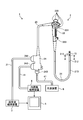
- FIG. 1 is a diagram schematically showing an ultrasonic endoscope system according to Embodiment 1 of the present invention.
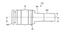
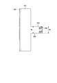
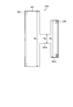
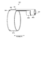
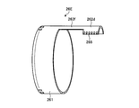
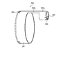
- FIG. 2 is a side view schematically showing the distal end configuration of the insertion portion of the ultrasonic endoscope according to the first embodiment of the present invention.
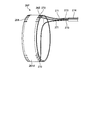
- FIG. 3 is a perspective view schematically showing the distal end configuration of the insertion portion of the ultrasonic endoscope according to the first embodiment of the present invention.
- 4 is a cross-sectional view taken along line AA shown in FIG. 5 is a cross-sectional view taken along line BB shown in FIG.
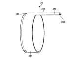
- FIG. 6 is a schematic diagram for explaining the configuration of the flexible substrate included in the ultrasonic endoscope according to the first embodiment of the present invention.
- FIG. 1 is a diagram schematically showing an ultrasonic endoscope system according to Embodiment 1 of the present invention.
- FIG. 2 is a side view schematically showing the distal end configuration of the insertion portion of the ultrasonic endoscope according to the first
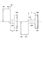
- FIG. 7 is a development view of the flexible substrate shown in FIG.
- FIG. 8 is a cross-sectional view schematically showing the distal end configuration of the insertion portion of the ultrasonic endoscope according to the second embodiment of the present invention.
- FIG. 9 is a schematic diagram illustrating a configuration of a flexible substrate included in the ultrasonic endoscope according to the second embodiment of the present invention.
- FIG. 10 is a development view of the flexible substrate shown in FIG.
- FIG. 11 is a schematic diagram illustrating a configuration of a flexible substrate included in the ultrasonic endoscope according to the first modification of the second embodiment of the present invention.
- FIG. 12 is a schematic diagram illustrating a configuration of a flexible substrate included in the ultrasonic endoscope according to the second modification of the second embodiment of the present invention.
- FIG. 13 is a development view of the flexible substrate shown in FIG.
- FIG. 14 is a schematic diagram illustrating a configuration of a flexible substrate included in the ultrasonic endoscope according to the third embodiment of the present invention.
- FIG. 15 is a plan view in the direction of arrow C in FIG.
- FIG. 16 is a schematic diagram illustrating a configuration of a flexible substrate included in the ultrasonic endoscope according to the fourth embodiment of the present invention.
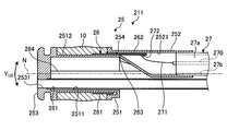
- FIG. 17 is a cross-sectional view schematically showing the distal end configuration of the insertion portion of the ultrasonic endoscope according to the fifth embodiment of the present invention.
- FIG. 18 is a schematic diagram for explaining a connection mode between a cable and a flexible board included in the ultrasonic endoscope according to the fifth embodiment of the present invention.
- FIG. 19 is a schematic diagram for explaining another example of the configuration of the flexible substrate included in the ultrasonic endoscope according to the embodiment of the present invention.
- FIG. 1 is a diagram schematically showing an ultrasonic endoscope system according to Embodiment 1 of the present invention.
- the endoscope system 1 is a system that performs ultrasonic diagnosis in a subject such as a person using an ultrasonic endoscope.
- the ultrasonic endoscope system 1 includes an ultrasonic endoscope 2, an ultrasonic observation device 3, an endoscope observation device 4, a display device 5, and a light source device 6. Prepare.
- the ultrasonic endoscope 2 is a combination of an observation optical system composed of a lens or the like and an endoscope observation unit having an imaging element and an ultrasonic probe, and has an endoscope observation function and an ultrasonic observation function. .
- the ultrasonic endoscope 2 converts an electrical pulse signal transmitted from the ultrasonic observation device 3 into an ultrasonic pulse (acoustic pulse) at the tip of the ultrasonic endoscope 2 and irradiates the subject, and is reflected by the subject.
- an ultrasonic transducer that converts the ultrasonic echo into an electrical echo signal expressed by a voltage change and outputs the electrical echo signal. The configuration of the ultrasonic transducer will be described later.
- the ultrasonic endoscope 2 includes an imaging optical system and an imaging element, and is inserted into a subject's digestive tract (esophagus, stomach, duodenum, large intestine) or respiratory organ (trachea, bronchus). Respiratory imaging can be performed.
- surrounding organs pancreas, gallbladder, bile duct, pancreatic duct, lymph node, organ in the mediastinum, blood vessels, etc.
- the ultrasonic endoscope 2 has a light guide that guides illumination light to be irradiated onto a subject during optical imaging.
- the light guide has a distal end reaching the distal end of the insertion portion of the ultrasonic endoscope 2 into the subject, and a proximal end portion connected to the light source device 6 that generates illumination light.
- the ultrasonic endoscope 2 includes an insertion unit 21, an operation unit 22, a universal cord 23, and a connector 24.
- the insertion part 21 is a part inserted into the subject.
- the insertion portion 21 includes a distal end hard portion 211 having an ultrasonic transducer 10 provided on the distal end side, and a bending portion 212 that is connected to the proximal end side of the distal end hard portion 211 and can be bent. And a flexible tube portion 213 connected to the proximal end side of the bending portion 212 and having flexibility.
- a light guide that transmits illumination light supplied from the light source device 6 and a plurality of signal cables that transmit various signals are inserted into the insertion portion 21.
- a channel (a treatment instrument channel described later) that forms a treatment instrument insertion passage for inserting the treatment instrument is inserted.
- the tip configuration of the insertion portion 21 will be described later.
- the operation unit 22 is a part that is connected to the proximal end side of the insertion unit 21 and receives various operations from a doctor or the like. As shown in FIG. 1, the operation unit 22 includes a bending knob 221 for performing a bending operation on the bending unit 212 and a plurality of operation members 222 for performing various operations.
- the operation section 22 is formed with a treatment instrument insertion port 223 that communicates with the treatment instrument channel and allows the treatment instrument to be inserted into the treatment instrument insertion path.
- the universal cord 23 is a cable that extends from the operation unit 22 and includes a plurality of signal cables that transmit various signals and an optical fiber that transmits illumination light supplied from the light source device 6.
- the connector 24 is provided at the tip of the universal cord 23.
- the connector 24 includes first to third connector portions 241 to 243 to which the ultrasonic cable 31, the video cable 41, and the light source device 6 are connected.
- the ultrasonic observation apparatus 3 is electrically connected to the ultrasonic endoscope 2 via the ultrasonic cable 31 (see FIG. 1), and outputs a pulse signal to the ultrasonic endoscope 2 via the ultrasonic cable 31.
- a pulse signal is input from the ultrasonic endoscope 2.
- the ultrasonic observation device 3 performs a predetermined process on the echo signal to generate an ultrasonic image.
- the endoscope observation apparatus 4 is electrically connected to the ultrasonic endoscope 2 via a video cable 41 (see FIG. 1), and an image signal from the ultrasonic endoscope 2 is input via the video cable 41. Is done. Then, the endoscope observation apparatus 4 performs a predetermined process on the image signal to generate an endoscope image.
- the display device 5 is configured using liquid crystal, organic EL (Electro Luminescence), or the like, and an ultrasonic image generated by the ultrasonic observation device 3 or an endoscope image generated by the endoscope observation device 4. Etc. are displayed.
- the light source device 6 supplies illumination light to the ultrasonic endoscope 2 through the optical fiber cable 61.
- FIG. 2 is a side view schematically showing the distal end configuration of the insertion portion of the ultrasonic endoscope according to the first embodiment of the present invention.
- FIG. 3 is a perspective view schematically showing the distal end configuration of the insertion portion of the ultrasonic endoscope according to the first embodiment of the present invention.
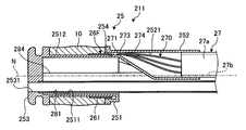
- 4 is a cross-sectional view taken along line AA in FIG. 5 is a cross-sectional view taken along line BB shown in FIG. 2 and 3 show the configuration of only the ultrasonic transducer 10 and the distal end hard portion 211 for explanation.
- the distal end hard portion 211 includes a hard member 25 formed using a hard material, a flexible substrate 26 provided at least partially inside the hard member 25, and the ultrasonic transducer 10 described above.
- the distal end hard portion 211 has an outer surface composed of the ultrasonic transducer 10 and the hard member 25 and has rigidity.
- the rigid member 25 includes a functional unit 251 that holds the ultrasonic transducer 10 on the side, and an ultrasonic wave that extends from the proximal end side of the functional unit 251 and is electrically connected to the ultrasonic transducer 10 via the flexible substrate 26. And a holding portion 252 that holds the cable 27.
- the rigid member 25 is formed with balloon locking portions that can lock one end and the other end of a balloon that can be filled with an ultrasonic medium on the distal end side and the proximal end side with respect to the ultrasonic transducer 10. ing.
- the function part 251 has a first hole part 2511, a part of the outer peripheral surface of the function part 251, a concave part 2512 to which the ultrasonic transducer 10 is attached, and a holding part that communicates with the first hole part 2511. Holes 2531 to 2534 are formed.
- the functional unit 251 communicates with the treatment instrument insertion passage formed in the insertion unit 21 to project the treatment tool from the distal end of the insertion unit 21 or to suck fluid such as liquid or gas in the subject.
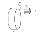
- a front-field optical unit that includes a treatment instrument channel 281, a light guide 282 that guides illumination light, one or a plurality of lenses, an image sensor, and the like, and receives observation light for generating a front-field image in the subject.
- the front visual field optical unit 283 corresponds to an imaging unit.
- the rigid member 25 has a holding hole 2531 for holding the end of the treatment instrument channel 281, a holding hole 2532 for holding the end of the light guide 282, and the front visual field optical part 283.
- a holding hole 2533 for holding the optical member to be held and a holding hole 2534 for holding the end portion of the air / water supply pipe 284 are formed.
- the treatment instrument channel 281, the light guide 282, the front visual field optical unit 283, and the air / water supply tube 284 are each held in a watertight manner in the holding holes 2531 to 2534.
- the treatment instrument channel 281 has an opening at the distal end in the longitudinal direction, and the opening communicates with the holding hole 2531.
- the holding part 252 is formed with a second hole part 2521 capable of holding the ultrasonic cable 27.
- the second hole portion 2521 has a hole shape that gradually increases in diameter from the distal end side toward the proximal end side and then extends with a uniform diameter.
- the maximum diameter among the outer diameters of the holding part 252 is smaller than the diameter of the first hole part 2511 of the functional part 251.
- the concave portion 2512 of the functional portion 251 and the second hole portion 2521 of the holding portion 252 communicate with each other via the communication portion 254.
- the ultrasonic transducer 10 irradiates ultrasonic waves in a direction perpendicular to the longitudinal direction around the axis parallel to the longitudinal direction of the insertion portion 21 (for example, the central axis N direction of the rigid member 211).
- the radial vibrator that scans the The ultrasonic transducer 10 is electronically scanned by arranging a plurality of piezoelectric elements along the circumferential direction and electronically switching the piezoelectric elements involved in transmission / reception or delaying transmission / reception of each piezoelectric element. Let The ultrasonic transducer 10 irradiates the observation target with ultrasonic waves when the piezoelectric element vibrates by the input of the pulse signal.
- ultrasonic waves reflected from the observation target are transmitted to the piezoelectric element.
- the piezoelectric element is vibrated by the transmitted ultrasonic wave, the piezoelectric element converts the vibration into an electrical signal, and is output as an echo signal to the ultrasonic observation apparatus 3 via the flexible substrate 26, the ultrasonic cable 27, and the like. To do.
- the ultrasonic transducer 10 sequentially vibrates each piezoelectric element, sequentially irradiates ultrasonic waves in the circumferential direction, and receives ultrasonic echoes reflected from the observation target. That is, the ultrasonic transducer 10 receives an ultrasonic echo that forms a cross-sectional image of an annular scanning surface around the ultrasonic transducer 10. Further, the ultrasonic transducer 10 has an outer surface in which the central portion of the ultrasonic transducer 10 along the longitudinal direction of the insertion portion 21 is in a direction perpendicular to the longitudinal direction as compared to both end portions of the longitudinal direction. It protrudes. In the ultrasonic transducer 10, for example, an acoustic lens forms the outer surface.
- the acoustic lens has a function of converging an ultrasonic wave in a convex shape toward the center, and emits an ultrasonic wave transmitted from the piezoelectric element to the outside or takes in an ultrasonic echo from the outside.
- the acoustic lens of the ultrasonic transducer 10 is described as having a convex shape in the case of using a material whose sound velocity is slower than that of the observation target, such as silicone.
- a concave acoustic lens material it is possible to use a concave acoustic lens material.
- the ultrasonic transducer 10 is connected to the flexible substrate 26.
- One end side of the flexible substrate 26 in the central axis N direction is connected to the ultrasonic transducer 10, and the other end side enters the second hole portion 2521 of the holding portion 252 through the communication portion 254.
- an electrode connected to each piezoelectric element of the ultrasonic transducer 10 and a wiring pattern formed on the flexible substrate 26 are fixed by a conductive fixing member such as solder.
- the flexible substrate 26 is connected to the ultrasonic cable 27 in the second hole portion 2521.
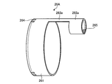
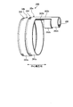
- FIG. 6 is a schematic diagram for explaining the configuration of the flexible substrate provided in the ultrasonic endoscope according to the first embodiment of the present invention.
- FIG. 7 is a development view of the flexible substrate shown in FIG.
- the flexible substrate 26 includes a first connection portion 261 connected to the ultrasonic transducer 10, a second connection portion 262 connected to each core wire 271 of the ultrasonic cable 27, and a first connection portion 261.
- the connection part 263 which connects the center part of the circumferential direction of this and the 2nd connection part 262 is provided.
- the first connection portion 261 is curved so that the same main surface faces each other, and has a ring shape in which a part in the circumferential direction is cut.
- electrodes a plurality of electrodes 264 in FIG. 7 connected to the respective electrodes of the ultrasonic transducer 10 are formed along the circumferential direction.
- the main surface here refers to the surface having the largest area.
- the second connection part 262 is curved on the same side as the first connection part 261.
- Each of the second connection portions 262 is an electrode connected to one of the electrodes (electrodes 264) formed on the first connection portion 262 by a wiring pattern (not shown), and the core wire of the ultrasonic cable 27 (see FIG. 5 (electrode 265 in FIG. 7) connected to the core wire 271) shown in FIG.
- the connecting portion 263 passes the above-described wiring pattern.
- the connecting portion 263 penetrates the communicating portion 254 in a state where the connecting portion 263 is disposed on the rigid member 25 (see FIG. 5).
- the width of the second connection portion 262 (width w 1 in FIG. 7) and the width of the connection portion 263 (width w 2 in FIG. 7) are: The same.
- the ultrasonic cable 27 is configured by covering a plurality of coaxial wires 270 provided according to the number of piezoelectric elements to be connected with an insulating jacket 27a.
- the jacket 27a covers a plurality of coaxial wires 270 collected in a bundle.
- a comprehensive shield 27b is provided on the inner periphery of the jacket 27a.
- a circle indicated by a broken line in FIG. 4 indicates the outer diameter of the jacket 27a.
- the coaxial wire 270 includes a conductive core wire (core wire 271), a dielectric layer (not shown) that covers the core wire 271, a shield (not shown) that covers the dielectric layer, and an insulating material that covers the shield. It consists of a protective film (not shown).
- FIG. 5 shows an example in which only one core wire 271 extends and is connected to the flexible substrate 26 by solder 272 for the sake of explanation, but in reality, the number of core wires (coaxial wire 270) is equal to the number of piezoelectric elements to be connected. Exists.
- the ultrasonic cable 27 is held by the holding portion 252 in a state where the jacket 27 a is inserted from the proximal end side of the holding portion 252. At this time, the jacket 27a is press-fitted into the holding portion 252 or fixed to the second hole 2521 of the holding portion 252 with an adhesive or the like.
- Each coaxial wire 270 is inserted into the insertion portion 21 in a state of being covered with the jacket 270 up to the holding portion 252, and the core wire 271 is exposed in the second hole portion 2521 of the holding portion 252.
- each coaxial line 270 is covered with the jacket 27a while being fixed from the flexible tube portion 213 through the bending portion 212 to the proximal end side of the distal end hard portion 211, and is fixed to the holding portion 252 while ensuring insulation. ing.
- the holding unit 252 is located near the outer periphery of the functional unit 251.
- the ultrasonic cable 27 held by the holding unit 252 is also located near the outer periphery of the functional unit 251. That is, in the first embodiment, the ultrasonic cable 27 is located near the outer periphery of the rigid member 25 in the radial direction orthogonal to the central axis N direction (see FIG. 4).
- the straight line L passing through the central axis N and orthogonal to the central axis N in the cross section passing through the end of the jacket 27 a in the distal end hard portion 211 is the center of the ultrasonic cable 27. And the center of the channel 281.
- the ultrasonic cable 27 and the channel 281 have a larger outer diameter than other contents. For this reason, the ultrasonic cable 27 and the channel 281 are disposed along the straight line L that passes through the central axis N and is orthogonal to the central axis N, thereby minimizing the diameter of the distal end hard portion 211. be able to.
- the straight line L is a bending direction of the bending portion 212, by a parallel to the curve direction Y UD corresponding to the vertical direction of the image to be imaged (see FIGS. 4 and 5), the Y UD direction when the curved, it is possible to suppress the vibration in the lateral direction Y LR orthogonal to the bending direction Y UD.
- the ultrasonic cable 27 formed by covering the plurality of coaxial wires 270 with the insulating jacket 27a is connected to the insulating hard member 25 positioned at the tip of the bending portion 212, In this rigid member 25, the core wire 271 is exposed and connected to the flexible substrate 26.
- the ultrasonic cable 27 is inserted into the bending portion 212 in a state where a plurality of coaxial lines are bundled by the jacket 27a and the comprehensive shield 27b disposed inside the jacket 27a, the coaxial line It is possible to reduce noise superimposed on and noise radiated from the coaxial line.
- the ultrasonic cable 27 in which a plurality of coaxial wires 270 are bundled passes through the bending portion 212, the area occupied by the ultrasonic cable 27 in the insertion portion 21 is smaller than that in the case of using a flexible substrate. Thus, the increase in diameter can be suppressed.
- the front visual field optical unit 283, and the channel 281 noise can be reduced and the increase in diameter of the insertion unit can be suppressed.
- the conventional configuration in which the coaxial line is connected to the flexible substrate on the proximal end side of the curved portion and the flexible substrate is inserted through the curved portion is easily affected by noise and is resistant to noise. It is difficult to reduce the diameter of the flexible substrate because it is necessary to increase the thickness of the flexible substrate.
- the ultrasonic cable 27 is secured to the rigid member 25 while ensuring insulation. Can be easily connected.
- the ultrasonic cable 27 is arranged in the bending portion 212 in a state where the coaxial line 270 is covered with the jacket 27a, the coaxial line is hardly broken.
- the jacket 27a covering the plurality of coaxial wires 270 and the holding portion 252 holding the jacket 27a ultrasonic waves with high electrical safety are provided. It can be an endoscope.
- FIG. 8 is a cross-sectional view schematically showing the distal end configuration of the insertion portion of the ultrasonic endoscope according to the second embodiment of the present invention.
- FIG. 9 is a schematic diagram illustrating a configuration of a flexible substrate included in the ultrasonic endoscope according to the second embodiment of the present invention.
- FIG. 10 is a development view of the flexible substrate shown in FIG.
- the distal end hard portion 211 of the ultrasonic endoscope 2 according to the second embodiment includes a flexible substrate 26A instead of the flexible substrate 26 in the configuration diagram of the first embodiment described above.
- the configuration is the same as that of the first embodiment described above except that the flexible substrate is changed.
- the flexible substrate 26 ⁇ / b> A has an annular shape in which a part in the circumferential direction is cut, and has a first connection part 261 connected to the ultrasonic transducer 10, an annular shape in which a part in the circumferential direction is cut, and each of the ultrasonic cables 27. It has the 2nd connection part 262a connected with the core wire 271, and the connection part 263a which connects the center parts of the circumferential direction of the 1st connection part 261 and the 2nd connection part 262a.
- Each of the second connecting portions 262a is an electrode connected to one of the electrodes formed on the first connecting portion 262 by a wiring pattern (not shown), and is a core wire of the ultrasonic cable 27 (the core wire shown in FIG. 8). 271) and electrodes (electrodes 265 in FIG. 10) are formed.
- the ground lines of the coaxial lines 270 are not shown, the ground lines are gathered together in the vicinity of the end portion of the jacket 27a on the base end side, and the electrodes on the ground side (outer peripheral surface side) of the piezoelectric element are flexible. They are connected via a dedicated pattern provided on the board 26A, or are connected via a connection cable provided separately.
- the wiring pattern described above passes through the connecting portion 263a.
- the connecting portion 263 a penetrates the communicating portion 254 in a state where it is disposed on the rigid member 25.
- the width of the first connecting portion 261 (width w 3 in FIG. 10), the width of the second connecting portion 262a (width w 4 in FIG. 10), and the width of the connecting portion 263a (in FIG. 10).
- the width w 5 has a relationship of w 5 ⁇ w 3 and w 5 ⁇ w 4 .
- the width of the first connecting portion 261 (width w 3 in FIG. 10), the width of the second connecting portion 262a (width w 4 in FIG. 10), and the width of the connecting portion 263a (
- the ultrasonic transducer 10 and the ultrasonic cable 27 are electrically connected by using a flexible substrate 26A having a relationship of w 5 ⁇ w 4 ⁇ w 3 with the width w 5 ) in FIG.
- a flexible substrate 26A having a relationship of w 5 ⁇ w 4 ⁇ w 3 with the width w 5
- interference between the adjacent core wires 271 can be more reliably suppressed, and workability when the core wire 271 is connected to the electrode 265 during manufacturing can be improved.
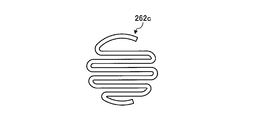
- the second connection portion 262a connected to each core wire 271 of the ultrasonic cable 27 does not have to be annular, and can be spiral or folded.
- the second connecting portion 262a and the spiral it is possible to increase the width w 4 capable of performing a connection with the cable.
- FIG. 11 is a schematic diagram illustrating a configuration of a flexible substrate included in the ultrasonic endoscope according to the first modification of the second embodiment of the present invention.
- the flexible substrate 26B according to the first modification is formed by overlapping a part of two flexible substrates (first flexible substrate 26a and second flexible substrate 26b).
- the first flexible substrate 26a has an annular shape with a part cut in the circumferential direction, the first connecting portion 261a connected to the ultrasonic transducer 10, the annular shape with a part cut in the circumferential direction, and the ultrasonic cable 27.
- a second connecting portion 262b connected to each of the core wires 271 and a connecting portion 263b connecting the circumferential central portions of the first connecting portion 261a and the second connecting portion 262b.
- the second flexible substrate 26b has the same configuration as the first flexible substrate 26a.
- the second flexible substrate 26b includes a first connection part 261a, a second connection part 262b, and a connection part 263b.
- electrodes 264 connected to the respective electrodes of the ultrasonic transducer 10 are formed along the circumferential direction.
- a plurality of electrodes 264 that are respectively connected to the piezoelectric elements of the ultrasonic transducer 10 are formed on the first connection portions 261a of the first flexible substrate 26a and the second flexible substrate 26b.
- Each of the second connection portions 262b of the first flexible substrate 26a and the second flexible substrate 26b is an electrode that is connected to one of the electrodes formed on the first connection portion 262a by a wiring pattern (not shown). Electrodes 265 connected to the core wire of the ultrasonic cable 27 (core wire 271 shown in FIG. 8) are respectively formed.
- all the electrodes 264 formed in the first connection portion 261 according to the second embodiment are arranged separately in the first connection portions 261a of the first flexible substrate 26a and the second flexible substrate 26b. Is done.
- all the electrodes 264 formed on the second connection portion 262a according to the second embodiment are arranged separately on the second connection portions 261b of the first flexible substrate 26a and the second flexible substrate 26b. For this reason, the number of electrodes 264 and 265 formed on each first connection portion 261a and each second connection portion 262b is formed on the first connection portion 261 and the second connection portion 262a according to Embodiment 2 described above. It can be about half of the number of electrodes.
- the wiring pattern described above passes through the connecting portion 263b.
- the width of the first connecting portion 261a, the width of the second connecting portion 262b, and the width of the connecting portion 263b are the same as the width relationship (w 5 ⁇ w 4 ⁇ w 3 ) of the second embodiment described above. Have a relationship.
- the first flexible substrate 26a and the second flexible substrate 26b are hard because the first connection portion 261a and the second connection portion 262b are adjacent to each other in the central axis N direction, and a part of the connection portions 263c and 263d overlap each other. It is disposed on the member 25.
- the overlapping connecting portion 263b passes through the communication portion 254.
- the flexible substrate 26B formed by overlapping the first flexible substrate 26a and the second flexible substrate 26b is formed.
- the number of the electrodes 264 and 265 formed in one first connection portion 261a and second connection portion 262b can be halved.
- the wiring density of the wiring patterns formed on the first flexible substrate 26a and the second flexible substrate 26b can be reduced, and it is possible to cope with the increase in the number of elements.
- connection part 263b since the connection part 263b is piled up and the communication part 254 is penetrated, it arrange
- the second connecting portions 262b of the first flexible substrate 26a and the second flexible substrate 26b are described as being adjacent to each other in the central axis N direction, but may be partially overlapped.
- FIG. 12 is a schematic diagram illustrating a configuration of a flexible substrate included in the ultrasonic endoscope according to the second modification of the second embodiment of the present invention.
- FIG. 13 is a development view of the flexible substrate shown in FIG.
- the flexible substrate 26C according to the second modification is formed by overlapping a part of two flexible substrates (a first flexible substrate 26c and a second flexible substrate 26d).
- the first flexible substrate 26c extends in an arc shape, forms a first connection portion 261b that connects to the ultrasonic transducer 10, and a ring that is partially cut in the circumferential direction, and is connected to each core wire 271 of the ultrasonic cable 27.
- the second connection part 262b, and a connecting part 263c that connects one end in the circumferential direction of the first connection part 261b and the central part in the circumferential direction of the second connection part 262b.
- the wiring pattern described above passes through the connecting portion 263c.
- the connecting portion 263 c penetrates the communicating portion 254 in a state where it is disposed on the rigid member 25.
- the second flexible substrate 26d extends in an arc shape that curves in a direction opposite to the first connection portion 261b, and has a first connection portion 261c that is connected to the ultrasonic transducer 10 and an annular shape that is partially cut off in the circumferential direction. None, a second connecting portion 262b connected to each core wire 271 of the ultrasonic cable 27, a connecting portion 263d connecting one end in the circumferential direction of the first connecting portion 261c and a central portion in the circumferential direction of the second connecting portion 262b, Have.
- the wiring pattern described above passes through the connecting portion 263d.
- the connecting portion 263 c penetrates the communicating portion 254 in a state where it is disposed on the rigid member 25.
- the second flexible substrate 26 d, the length d 2 between the first connecting portion 261c and the second connecting portion 262b by connecting the connecting portion 263d is in the first flexible substrate 26c, the first connection by connecting the connecting portion 263c It is larger than the length d 1 between the part 261b and the second connection part 262b.
- the first flexible substrate 26c and the second flexible substrate 26d are disposed on the rigid member 25 such that the second connection portions 262b are adjacent to each other and a part of the connection portion 263b overlaps. Overlapping connecting portions 263c and 263d pass through the communication portion 254. At this time, the first connection portions 261 b and 261 c extend in an arc shape on the opposite sides to form an intermittent cylinder having an inner diameter along the surface of the recess 2512.
- the wiring density of the wiring pattern can be reduced, and it is possible to cope with the increase in the number of elements.
- the piezoelectric element and the two flexible substrates 26c and 26d can be connected at the base end side end portion of the piezoelectric element, and the connection between the piezoelectric element and the flexible substrate is easier. It becomes.
- the width of the second connection portion 262b is increased from the first connection portion 261b, so that the pitch of the electrodes 265 to be connected to the cable is set as described in the second embodiment. Therefore, the positioning of the flexible board and the cable is facilitated, and the wiring work is facilitated.
- FIG. 14 is a schematic diagram illustrating a configuration of a flexible substrate included in the ultrasonic endoscope according to the third embodiment of the present invention.
- FIG. 15 is a plan view in the direction of arrow C in FIG. 14 and is a plan view showing the configuration of the second connection portion 262D.
- the distal end hard portion 211 of the ultrasonic endoscope 2 according to the third embodiment includes a flexible substrate 26D instead of the flexible substrate 26 having the configuration of the first embodiment described above (see FIG. 2).
- the configuration is the same as that of the first embodiment described above except that the flexible substrate is changed.
- the flexible substrate 26 ⁇ / b> D has an annular shape with a part cut in the circumferential direction, and has a first connection part 261 connected to the ultrasonic transducer 10, an annular shape with a part cut in the circumferential direction, and each of the ultrasonic cables 27. It has the 2nd connection part 262c connected with the core wire 271, and the connection part 263e which connects the 1st connection part 261 and the 2nd connection part 262c.
- the second connection part 262c has a zigzag shape in which the extending direction is reversed along the longitudinal direction.
- Each of the second connection portions 262c is an electrode connected to any one of the electrodes formed on the first connection portion 261 by a wiring pattern (not shown), and is connected to the core wire 271 of the ultrasonic cable 27 ( For example, electrodes 265) are formed respectively.
- the circle circumscribing the second connection portion 262 c is smaller than the inner diameter of the second hole portion 2521.
- the longitudinal direction of the band-shaped constituent part constituting the second connecting part 262c is orthogonal to the above-described central axis N direction.
- the second connecting portion 262c may be formed by using a zigzag band-shaped component along the longitudinal direction parallel to the central axis N direction described above.
- the wiring pattern described above passes through the connecting portion 263e.
- the connecting portion 263 e penetrates the communicating portion 254 in a state where it is disposed on the rigid member 25.
- the ultrasonic transducer 10 and the ultrasonic cable 27 are electrically connected using the flexible substrate 26D having the second connection portion 262c having a zigzag shape.
- FIG. 16 is a schematic diagram illustrating a configuration of a flexible substrate included in the ultrasonic endoscope according to the fourth embodiment of the present invention.
- the distal end hard portion 211 of the ultrasonic endoscope 2 according to the fourth embodiment includes a flexible substrate 26E instead of the flexible substrate 26 having the configuration of the first embodiment described above (see FIG. 2).
- the configuration is the same as that of the first embodiment described above except that the flexible substrate is changed.
- the flexible substrate 26 ⁇ / b> E has an annular shape in which a part in the circumferential direction is cut, and has a first connection part 261 connected to the ultrasonic transducer 10, an annular shape in which a part in the circumferential direction is cut, and each of the ultrasonic cables 27. It has the 2nd connection part 262d connected with the core wire 271, and the connection part 263f which connects the center parts of the circumferential direction of the 1st connection part 261 and the 2nd connection part 262d.
- Each of the second connection portions 262d is an electrode connected to one of the electrodes formed on the first connection portion 262 with a wiring pattern (not shown), and is connected to the core wire 271 of the ultrasonic cable 27. Are formed respectively.
- the electrode 265 is formed on the same side as the side on which the electrode 264 of the first connection portion 261 is formed, and the longitudinal direction is parallel to the width direction. Each electrode 265 is formed along the direction perpendicular to the width direction on the surface of the second connection portion 262d. Further, the second connection portion 262d has a width larger than that of the connecting portion 263f.
- the wiring pattern described above passes through the connecting portion 263f.
- the connecting portion 263 f penetrates the communicating portion 254 in a state where the connecting portion 263 f is disposed on the rigid member 25.
- each electrode 265 is formed along the direction perpendicular to the width direction on the surface of the second connection portion 262d. Even in such a configuration, it is possible to reduce the wiring density of the wiring pattern as described above, and it is possible to cope with the increase in the number of elements.
- the electrode 265 has been described as having the longitudinal direction parallel to the width direction.
- the longitudinal direction may be parallel to the width direction
- the longitudinal direction may be parallel to the width direction.
- And may be inclined (for example, making an acute angle).
- FIG. 17 is a cross-sectional view schematically showing the distal end configuration of the insertion portion of the ultrasonic endoscope according to the fifth embodiment of the present invention.
- FIG. 18 is a schematic diagram for explaining a connection mode between a cable and a flexible board included in the ultrasonic endoscope according to the fifth embodiment of the present invention.
- the distal end hard portion 211 of the ultrasonic endoscope 2 according to the fifth embodiment includes a flexible substrate 26F instead of the flexible substrate 26 in the configuration diagram of the first embodiment described above.
- the connecting portion that connects the first connecting portion and the second connecting portion in the flexible substrate has been described as passing through the communicating portion. Part of the through hole penetrates the communication part 254.
- the flexible substrate 26F has an annular shape with a part cut in the circumferential direction, and includes a main body portion 261d connected to the ultrasonic transducer 10 at one end side and connected to each core wire 271 of the ultrasonic cable 27 at the other end side.
- the main body 261d has an annular shape in which a part in the circumferential direction is cut.
- electrodes 264 connected to the respective electrodes of the ultrasonic transducer 10 are formed along the circumferential direction, and each of the electrodes formed on the first connection portion 261 by a wiring pattern (not shown).
- An electrode 265 that is connected to any one of the electrodes 265 and connected to the core wire 271 of the ultrasonic cable 27 is formed along the circumferential direction.
- the coaxial wire 270 extends from the second hole portion 2521 to the communication portion 254 in a state where the core wire 271 is covered with the protective film 274 and passes through the communication portion 254, so that the shield 273 is exposed.
- Each coaxial wire 270 circulates along the flexible substrate 26 ⁇ / b> F with the core wire 271 (or insulating layer) exposed in the recess 2512, and is connected to the connection target electrode 265 by the solder 272.
- the electrode 265 is inclined with respect to the central axis N as it is away from the communication portion 254. That is, the longitudinal direction of the connection surface of the electrode 265 is inclined along the direction in which the core wire 271 of the coaxial line 270 to be connected enters.
- the coaxial wire 270 passes through the communication portion 254, and the electrode 265 inclined along the direction in which the core wire 271 enters and the core wire 271 are connected. Even in such a configuration, it is possible to reduce the wiring density of the wiring pattern as described above, and it is possible to cope with the increase in the number of elements. Further, since the longitudinal direction of the electrode 265 is aligned with the core wire 271, the stress applied to the core wire 271 connected to the electrode 265 can be reduced.
- the coaxial line 270 and the piezoelectric element may be directly connected without using the flexible substrate 26F.
- the electrode 265 is described as having the longitudinal direction parallel to the width direction.
- the longitudinal direction may be parallel to the width direction, or the longitudinal direction may be parallel to the width direction. And may be inclined (for example, inclined so that the longitudinal direction and the width direction form an acute angle).
- the electrodes 264 and 265 are provided on one surface of the flexible substrate.
- the electrode formation surface may be the opposite surface, for example, As shown in the flexible substrate 26G shown in FIG. 19, the electrodes 265 may be formed on both surfaces.
- the plurality of electrodes are arranged in a line along the circumferential direction
- these electrodes may be arranged in a plurality of lines along the circumferential direction.
- the ultrasonic endoscope according to the present invention has a configuration including a radial ultrasonic transducer, a front-view optical system, and a channel, which reduces noise and has a large diameter insertion portion. It is useful for suppressing crystallization.
Abstract
This ultrasound endoscope is provided with the following: an insertion part having a hard tip portion, a curved portion, and a flexible tube; a radial ultrasonic transducer; an imaging unit that captures images of a visual field to the front of the insertion part in the longitudinal direction; a channel one end of which has an opening at the longitudinal-direction tip of the hard tip portion; a plurality of coaxial lines that are electrically connected to a plurality of piezoelectric elements, respectively; and an ultrasound cable having a metal composite shield that covers the plurality of coaxial lines, and an insulating jacket that covers the composite shield, the jacket reaching from the flexible tube portion, past the curved portion, and to the base end of the hard tip portion in a state of covering the plurality of coaxial lines, and being fixed to the base end of the hard tip portion and near the outer circumferential side thereof.
Description
本発明は、超音波を観測対象へ出射するとともに、観測対象で反射された超音波エコーを受信してエコー信号に変換して出力するラジアル型の超音波振動子と、被検体内を観察する光学系とを備えた超音波内視鏡に関する。
The present invention emits ultrasonic waves to an observation target, receives a ultrasonic echo reflected from the observation target, converts it into an echo signal, and outputs it, and observes the inside of the subject. The present invention relates to an ultrasonic endoscope provided with an optical system.
観測対象である生体組織または材料の特性を観測するために、超音波を適用することがある。具体的には、超音波観測装置が、超音波を送受信する超音波振動子から受信した超音波エコーに対して所定の信号処理を施すことにより、観測対象の特性に関する情報を取得することができる。
∙ Ultrasound may be applied to observe the characteristics of the biological tissue or material that is the object of observation. Specifically, the ultrasonic observation apparatus can acquire information on the characteristics of the observation target by performing predetermined signal processing on the ultrasonic echo received from the ultrasonic transducer that transmits and receives ultrasonic waves. .
超音波振動子は、電気的なパルス信号を超音波パルス(音響パルス)に変換して観測対象へ照射するとともに、観測対象で反射された超音波エコーを電気的なエコー信号に変換して出力する複数の圧電素子を備える。例えば、複数の圧電素子を所定の方向に沿って並べて、送受信にかかわる素子を電子的に切り替えたり、各素子の送受信に遅延をかけたりすることで、観測対象から超音波エコーを取得する。
The ultrasonic transducer converts an electrical pulse signal into an ultrasonic pulse (acoustic pulse) and irradiates the observation target, and converts an ultrasonic echo reflected from the observation target into an electrical echo signal for output. A plurality of piezoelectric elements. For example, an ultrasonic echo is acquired from an observation target by arranging a plurality of piezoelectric elements along a predetermined direction and electronically switching elements involved in transmission / reception or delaying transmission / reception of each element.
超音波振動子には、コンベックス型、リニア型、ラジアル型等、超音波による走査範囲が異なる複数の種別があることが知られている。このうち、ラジアル型の超音波振動子は、複数の圧電素子が、所定の軸のまわりに周回して配列され、超音波ビームをこの軸と直交する径方向に出射する。例えば、特許文献1には、ラジアル型の超音波振動子を先端に有し、被検体内を観察するための前方視光学系と、先端から処置具を突出させたり、被検体内の液体または気体などの流体を吸引したりするチャンネルとが挿通されている挿入部を備えた超音波内視鏡が開示されている。特許文献1が開示する超音波内視鏡は、配線パターンが形成されたフレキシブル基板が、前方視光学系やチャンネルの周囲に設けられている。フレキシブル基板は、超音波振動子の基端側から湾曲部に延び、湾曲部の基端側に連なる可撓管部の先端において超音波ケーブルに接続されている。
It is known that there are a plurality of types of ultrasonic transducers, such as a convex type, a linear type, and a radial type, which have different ultrasonic scanning ranges. Among these, in the radial type ultrasonic transducer, a plurality of piezoelectric elements are arranged around a predetermined axis and emit an ultrasonic beam in a radial direction perpendicular to the axis. For example, in Patent Document 1, a front-side optical system for observing the inside of a subject having a radial ultrasonic transducer at the tip, a treatment tool protruding from the tip, a liquid in the subject, An ultrasonic endoscope having an insertion portion into which a channel for sucking fluid such as gas is inserted is disclosed. In the ultrasonic endoscope disclosed in Patent Document 1, a flexible substrate on which a wiring pattern is formed is provided around a front vision optical system and a channel. The flexible substrate extends from the proximal end side of the ultrasonic transducer to the bending portion, and is connected to the ultrasonic cable at the distal end of the flexible tube portion connected to the proximal end side of the bending portion.
特許文献1が開示する超音波内視鏡では、フレキシブル基板を伝送する信号にノイズが重畳し、得られる画像の画質が劣化することがあった。ノイズを抑えるには、例えば、フレキシブル基板の外周に金属箔などの導電性材料によるシールドを設ければよいが、この場合には、フレキシブル基板を配設するためのスペースが増大して挿入部の太径化を招く。このように、ノイズによる画質劣化の抑制と、挿入部の太径化の抑制とはトレードオフの関係があった。
In the ultrasonic endoscope disclosed in Patent Document 1, noise is superimposed on a signal transmitted through a flexible substrate, and the quality of an obtained image may be deteriorated. In order to suppress the noise, for example, a shield made of a conductive material such as a metal foil may be provided on the outer periphery of the flexible substrate. In this case, however, the space for disposing the flexible substrate increases, Increases diameter. Thus, there was a trade-off relationship between the suppression of image quality degradation due to noise and the suppression of the increase in diameter of the insertion portion.
本発明は、上記に鑑みてなされたものであって、ラジアル型の超音波振動子と、前方視光学系と、チャンネルとを備えた構成において、ノイズを低減し、かつ挿入部の太径化を抑制することができる超音波内視鏡を提供することを目的とする。
The present invention has been made in view of the above, and in a configuration including a radial ultrasonic transducer, a forward-viewing optical system, and a channel, noise is reduced and the diameter of the insertion portion is increased. An object of the present invention is to provide an ultrasonic endoscope capable of suppressing the above.
上述した課題を解決し、目的を達成するために、本発明に係る超音波内視鏡は、硬質性の先端硬質部と、前記先端硬質部の基端側に連結され、少なくとも一つの方向に湾曲自在な湾曲部と、前記湾曲部の基端側に連結され、可撓性を有する可撓管部とを有する挿入部と、超音波を送受信可能な複数の圧電素子が前記先端硬質部の周方向に沿って環状に並んでおり、前記挿入部の長手方向と垂直な方向に前記超音波を照射する超音波振動子と、前記先端硬質部に設けられ、前記挿入部の長手方向の前方の視野の画像を撮像する撮像部と、前記挿入部の内部に挿通され、一端が前記先端硬質部の長手方向の先端に開口を有するチャンネルと、前記複数の圧電素子とそれぞれ電気的に接続する複数の同軸線と、該複数の同軸線を被覆する金属製の総合シールド、および前記総合シールドを被覆する絶縁性のジャケットを有し、前記ジャケットが、前記複数の同軸線を被覆した状態で前記可撓管部から前記湾曲部を経て前記先端硬質部の基端側に達するとともに、前記先端硬質部の基端側かつ外周寄りに固定されている超音波ケーブルと、を備えることを特徴とする。
In order to solve the above-described problems and achieve the object, an ultrasonic endoscope according to the present invention is connected to a hard distal end hard portion and a proximal end side of the distal end hard portion in at least one direction. An insertion portion having a bendable bending portion, a flexible tube portion connected to the proximal end side of the bending portion and having flexibility, and a plurality of piezoelectric elements capable of transmitting and receiving ultrasonic waves are provided on the distal end hard portion. An ultrasonic transducer that is arranged in a ring along the circumferential direction and irradiates the ultrasonic wave in a direction perpendicular to the longitudinal direction of the insertion portion, and is provided at the distal end hard portion and forward in the longitudinal direction of the insertion portion An imaging unit that captures an image of the field of view, a channel that is inserted into the insertion unit and has an opening at the distal end in the longitudinal direction of the distal end hard portion, and the plurality of piezoelectric elements, respectively. A plurality of coaxial wires and a metal covering the plurality of coaxial wires An insulating jacket that covers the combined shield and the overall shield, and the jacket covers the plurality of coaxial lines from the flexible tube portion through the curved portion to the proximal end of the distal end hard portion And an ultrasonic cable fixed to the proximal end side of the distal end hard portion and closer to the outer periphery.
また、本発明に係る超音波内視鏡は、上記発明において、前記複数の圧電素子と前記複数の同軸線とは、フレキシブル基板を介して電気的に接続されることを特徴とする。
The ultrasonic endoscope according to the present invention is characterized in that, in the above invention, the plurality of piezoelectric elements and the plurality of coaxial lines are electrically connected via a flexible substrate.
また、本発明に係る超音波内視鏡は、上記発明において、前記フレキシブル基板は、環状に湾曲し、前記複数の圧電素子と電気的に接続する第1接続部と、前記第1接続部の湾曲態様と同じ側に湾曲した環状をなしており、前記第1接続部および前記複数の同軸線と電気的に接続する第2接続部と、前記第1接続部および前記第2接続部を連結する連結部と、を有し、前記連結部は、前記第1接続部および前記第2接続部の周方向に沿って延びる長さが、前記第2接続部における周方向の長さよりも小さいことを特徴とする。
In the ultrasonic endoscope according to the present invention, in the above invention, the flexible board is curved in an annular shape and electrically connected to the plurality of piezoelectric elements, and the first connection part It has an annular shape that is curved on the same side as the bending mode, and connects the first connection portion and the second connection portion that is electrically connected to the plurality of coaxial lines, and the first connection portion and the second connection portion. A connecting portion that has a length extending along a circumferential direction of the first connecting portion and the second connecting portion is smaller than a circumferential length of the second connecting portion. It is characterized by.
また、本発明に係る超音波内視鏡は、上記発明において、前記第2接続部における周方向の長さは、前記第1接続部における周方向の長さよりも小さいことを特徴とする。
The ultrasonic endoscope according to the present invention is characterized in that, in the above invention, the circumferential length of the second connecting portion is smaller than the circumferential length of the first connecting portion.
また、本発明に係る超音波内視鏡は、上記発明において、前記第2接続部における周方向の長さは、前記第1接続部における周方向の長さよりも大きいことを特徴とする。
The ultrasonic endoscope according to the present invention is characterized in that, in the above invention, the circumferential length of the second connecting portion is larger than the circumferential length of the first connecting portion.
また、本発明に係る超音波内視鏡は、上記発明において、前記フレキシブル基板は、各々が前記第1接続部、前記第2接続部および前記連結部を有する第1フレキシブル基板および第2フレキシブル基板を有し、前記第1フレキシブル基板および前記第2フレキシブル基板の各連結部の一部が重なっていることを特徴とする。
In the ultrasonic endoscope according to the present invention, in the above invention, the flexible substrate includes a first flexible substrate and a second flexible substrate each having the first connecting portion, the second connecting portion, and the connecting portion. And a part of each connecting portion of the first flexible substrate and the second flexible substrate overlap each other.
また、本発明に係る超音波内視鏡は、上記発明において、前記第1フレキシブル基板の前記第2接続部と、前記第2フレキシブル基板の前記第2接続部とは、前記長手方向に沿って並んでいることを特徴とする。
In the ultrasonic endoscope according to the present invention, in the above invention, the second connection portion of the first flexible substrate and the second connection portion of the second flexible substrate are along the longitudinal direction. It is characterized by being lined up.
また、本発明に係る超音波内視鏡は、上記発明において、前記第2接続部は、長手方向に沿ってジグザグ状をなすことを特徴とする。
Also, the ultrasonic endoscope according to the present invention is characterized in that, in the above-mentioned invention, the second connecting portion has a zigzag shape along the longitudinal direction.
また、本発明に係る超音波内視鏡は、上記発明において、前記第2接続部には、前記複数の同軸線とそれぞれ接続する複数の電極を有し、前記複数の電極は、前記フレキシブル基板の一方の面に形成されることを特徴とする。
In the ultrasonic endoscope according to the present invention, in the above invention, the second connection portion includes a plurality of electrodes respectively connected to the plurality of coaxial lines, and the plurality of electrodes are the flexible substrate. It is formed in one side of this.
また、本発明に係る超音波内視鏡は、上記発明において、前記第2接続部には、前記複数の同軸線とそれぞれ接続する複数の電極を有し、前記複数の電極は、前記フレキシブル基板の両面に形成されることを特徴とする。
In the ultrasonic endoscope according to the present invention, in the above invention, the second connection portion includes a plurality of electrodes respectively connected to the plurality of coaxial lines, and the plurality of electrodes are the flexible substrate. It is characterized by being formed on both sides.
また、本発明に係る超音波内視鏡は、上記発明において、前記フレキシブル基板は、前記複数の圧電素子とそれぞれ電気的に接続する複数の第1電極と、前記第1電極および前記複数の同軸線とそれぞれ電気的に接続する複数の第2電極とを有し、各第2電極は、接続面の長手方向が、前記同軸線の芯線が進入する方向に沿って傾斜していることを特徴とする。
In the ultrasonic endoscope according to the present invention, in the above invention, the flexible substrate includes a plurality of first electrodes electrically connected to the plurality of piezoelectric elements, the first electrode, and the plurality of coaxials. A plurality of second electrodes that are electrically connected to the wires, and each second electrode has a longitudinal direction of a connection surface inclined along a direction in which the core wire of the coaxial line enters. And
また、本発明に係る超音波内視鏡は、上記発明において、前記先端硬質部における前記ジャケットの端部を通過する断面において、前記超音波ケーブルの中心と、前記チャンネルの中心とを通過する直線は、前記挿入部の中心軸を通過することを特徴とする。
The ultrasonic endoscope according to the present invention is the straight line passing through the center of the ultrasonic cable and the center of the channel in the cross section passing through the end of the jacket in the hard tip portion. Pass through the central axis of the insertion part.
また、本発明に係る超音波内視鏡は、上記発明において、前記直線は、前記撮像部により撮像される画像の上下方向に相当する方向と平行であることを特徴とする。
The ultrasonic endoscope according to the present invention is characterized in that, in the above invention, the straight line is parallel to a direction corresponding to a vertical direction of an image captured by the imaging unit.
本発明によれば、ラジアル型の超音波振動子と、前方視光学系と、チャンネルとを備えた構成において、ノイズを低減し、かつ挿入部の太径化を抑制することができるという効果を奏する。
According to the present invention, in the configuration including the radial ultrasonic transducer, the forward viewing optical system, and the channel, it is possible to reduce noise and suppress the increase in the diameter of the insertion portion. Play.
以下に、図面を参照して、本発明を実施するための形態(以下、実施の形態)について説明する。なお、以下に説明する実施の形態によって本発明が限定されるものではない。さらに、図面の記載において、同一の部分には同一の符号を付している。
DETAILED DESCRIPTION Hereinafter, modes for carrying out the present invention (hereinafter referred to as embodiments) will be described with reference to the drawings. The present invention is not limited to the embodiments described below. Furthermore, the same code | symbol is attached | subjected to the same part in description of drawing.
(実施の形態1)
図1は、本発明の実施の形態1に係る超音波内視鏡システムを模式的に示す図である。内視鏡システム1は、超音波内視鏡を用いて人等の被検体内の超音波診断を行うシステムである。この超音波内視鏡システム1は、図1に示すように、超音波内視鏡2と、超音波観測装置3と、内視鏡観察装置4と、表示装置5と、光源装置6とを備える。 (Embodiment 1)
FIG. 1 is a diagram schematically showing an ultrasonic endoscope system according toEmbodiment 1 of the present invention. The endoscope system 1 is a system that performs ultrasonic diagnosis in a subject such as a person using an ultrasonic endoscope. As shown in FIG. 1, the ultrasonic endoscope system 1 includes an ultrasonic endoscope 2, an ultrasonic observation device 3, an endoscope observation device 4, a display device 5, and a light source device 6. Prepare.
図1は、本発明の実施の形態1に係る超音波内視鏡システムを模式的に示す図である。内視鏡システム1は、超音波内視鏡を用いて人等の被検体内の超音波診断を行うシステムである。この超音波内視鏡システム1は、図1に示すように、超音波内視鏡2と、超音波観測装置3と、内視鏡観察装置4と、表示装置5と、光源装置6とを備える。 (Embodiment 1)
FIG. 1 is a diagram schematically showing an ultrasonic endoscope system according to
超音波内視鏡2は、レンズ等で構成される観察光学系及び撮像素子を有する内視鏡観察部に超音波プローブを組み合わせたものであり、内視鏡観察機能及び超音波観測機能を有する。超音波内視鏡2は、その先端に、超音波観測装置3から送信された電気的なパルス信号を超音波パルス(音響パルス)に変換して被検体へ照射するとともに、被検体で反射された超音波エコーを電圧変化で表現する電気的なエコー信号に変換して出力する超音波振動子を有する。超音波振動子の構成については、後述する。
The ultrasonic endoscope 2 is a combination of an observation optical system composed of a lens or the like and an endoscope observation unit having an imaging element and an ultrasonic probe, and has an endoscope observation function and an ultrasonic observation function. . The ultrasonic endoscope 2 converts an electrical pulse signal transmitted from the ultrasonic observation device 3 into an ultrasonic pulse (acoustic pulse) at the tip of the ultrasonic endoscope 2 and irradiates the subject, and is reflected by the subject. And an ultrasonic transducer that converts the ultrasonic echo into an electrical echo signal expressed by a voltage change and outputs the electrical echo signal. The configuration of the ultrasonic transducer will be described later.
超音波内視鏡2は、撮像光学系および撮像素子を有しており、被検体の消化管(食道、胃、十二指腸、大腸)、または呼吸器(気管、気管支)へ挿入され、消化管や、呼吸器の撮像を行うことが可能である。また、その周囲臓器(膵臓、胆嚢、胆管、膵管、リンパ節、縦隔内の臓器、血管等)を、超音波を用いて撮像することが可能である。また、超音波内視鏡2は、光学撮像時に被検体へ照射する照明光を導くライトガイドを有する。このライトガイドは、先端が超音波内視鏡2の被検体への挿入部の先端まで達している一方、基端部が照明光を発生する光源装置6に接続されている。
The ultrasonic endoscope 2 includes an imaging optical system and an imaging element, and is inserted into a subject's digestive tract (esophagus, stomach, duodenum, large intestine) or respiratory organ (trachea, bronchus). Respiratory imaging can be performed. In addition, surrounding organs (pancreas, gallbladder, bile duct, pancreatic duct, lymph node, organ in the mediastinum, blood vessels, etc.) can be imaged using ultrasound. In addition, the ultrasonic endoscope 2 has a light guide that guides illumination light to be irradiated onto a subject during optical imaging. The light guide has a distal end reaching the distal end of the insertion portion of the ultrasonic endoscope 2 into the subject, and a proximal end portion connected to the light source device 6 that generates illumination light.
超音波内視鏡2は、図1に示すように、挿入部21と、操作部22と、ユニバーサルコード23と、コネクタ24とを備える。挿入部21は、被検体内に挿入される部分である。この挿入部21は、図1に示すように、先端側に設けられる超音波振動子10を有する先端硬質部211と、先端硬質部211の基端側に連結され湾曲可能とする湾曲部212と、湾曲部212の基端側に連結され可撓性を有する可撓管部213とを備える。ここで、挿入部21の内部には、具体的な図示は省略したが、光源装置6から供給された照明光を伝送するライトガイド、各種信号を伝送する複数の信号ケーブルが挿通されているとともに、処置具を挿通するための処置具用挿通路を形成するチャンネル(後述する処置具チャンネル)が挿通されている。挿入部21の先端構成については、後述する。
As shown in FIG. 1, the ultrasonic endoscope 2 includes an insertion unit 21, an operation unit 22, a universal cord 23, and a connector 24. The insertion part 21 is a part inserted into the subject. As shown in FIG. 1, the insertion portion 21 includes a distal end hard portion 211 having an ultrasonic transducer 10 provided on the distal end side, and a bending portion 212 that is connected to the proximal end side of the distal end hard portion 211 and can be bent. And a flexible tube portion 213 connected to the proximal end side of the bending portion 212 and having flexibility. Here, although not specifically shown in the drawing, a light guide that transmits illumination light supplied from the light source device 6 and a plurality of signal cables that transmit various signals are inserted into the insertion portion 21. A channel (a treatment instrument channel described later) that forms a treatment instrument insertion passage for inserting the treatment instrument is inserted. The tip configuration of the insertion portion 21 will be described later.
操作部22は、挿入部21の基端側に連結され、医師等からの各種操作を受け付ける部分である。この操作部22は、図1に示すように、湾曲部212を湾曲操作するための湾曲ノブ221と、各種操作を行うための複数の操作部材222とを備える。また、操作部22には、処置具チャンネルに連通し、当該処置具用挿通路に処置具を挿通するための処置具挿入口223が形成されている。
The operation unit 22 is a part that is connected to the proximal end side of the insertion unit 21 and receives various operations from a doctor or the like. As shown in FIG. 1, the operation unit 22 includes a bending knob 221 for performing a bending operation on the bending unit 212 and a plurality of operation members 222 for performing various operations. The operation section 22 is formed with a treatment instrument insertion port 223 that communicates with the treatment instrument channel and allows the treatment instrument to be inserted into the treatment instrument insertion path.
ユニバーサルコード23は、操作部22から延在し、各種信号を伝送する複数の信号ケーブル、および光源装置6から供給された照明光を伝送する光ファイバ等が配設されたケーブルである。
The universal cord 23 is a cable that extends from the operation unit 22 and includes a plurality of signal cables that transmit various signals and an optical fiber that transmits illumination light supplied from the light source device 6.
コネクタ24は、ユニバーサルコード23の先端に設けられている。そして、コネクタ24は、超音波ケーブル31、ビデオケーブル41、および光源装置6がそれぞれ接続される第1~第3コネクタ部241~243を備える。
The connector 24 is provided at the tip of the universal cord 23. The connector 24 includes first to third connector portions 241 to 243 to which the ultrasonic cable 31, the video cable 41, and the light source device 6 are connected.
超音波観測装置3は、超音波ケーブル31(図1参照)を介して超音波内視鏡2に電気的に接続し、超音波ケーブル31を介して超音波内視鏡2にパルス信号を出力するとともに超音波内視鏡2からエコー信号が入力される。そして、超音波観測装置3は、当該エコー信号に所定の処理を施して超音波画像を生成する。
The ultrasonic observation apparatus 3 is electrically connected to the ultrasonic endoscope 2 via the ultrasonic cable 31 (see FIG. 1), and outputs a pulse signal to the ultrasonic endoscope 2 via the ultrasonic cable 31. In addition, an echo signal is input from the ultrasonic endoscope 2. Then, the ultrasonic observation device 3 performs a predetermined process on the echo signal to generate an ultrasonic image.
内視鏡観察装置4は、ビデオケーブル41(図1参照)を介して超音波内視鏡2に電気的に接続し、ビデオケーブル41を介して超音波内視鏡2からの画像信号が入力される。そして、内視鏡観察装置4は、当該画像信号に所定の処理を施して内視鏡画像を生成する。
The endoscope observation apparatus 4 is electrically connected to the ultrasonic endoscope 2 via a video cable 41 (see FIG. 1), and an image signal from the ultrasonic endoscope 2 is input via the video cable 41. Is done. Then, the endoscope observation apparatus 4 performs a predetermined process on the image signal to generate an endoscope image.
表示装置5は、液晶または有機EL(Electro Luminescence)などを用いて構成され、超音波観測装置3にて生成された超音波画像や、内視鏡観察装置4にて生成された内視鏡画像等を表示する。
The display device 5 is configured using liquid crystal, organic EL (Electro Luminescence), or the like, and an ultrasonic image generated by the ultrasonic observation device 3 or an endoscope image generated by the endoscope observation device 4. Etc. are displayed.
光源装置6は、光ファイバケーブル61を介して照明光を超音波内視鏡2に供給する。
The light source device 6 supplies illumination light to the ultrasonic endoscope 2 through the optical fiber cable 61.
図2は、本発明の実施の形態1に係る超音波内視鏡の挿入部の先端構成を模式的に示す側面図である。図3は、本発明の実施の形態1に係る超音波内視鏡の挿入部の先端構成を模式的に示す斜視図である。図4は、図1のA-A線断面図である。図5は、図2に示すB-B線断面図である。図2および図3は、説明のため、超音波振動子10および先端硬質部211のみの構成を示している。
FIG. 2 is a side view schematically showing the distal end configuration of the insertion portion of the ultrasonic endoscope according to the first embodiment of the present invention. FIG. 3 is a perspective view schematically showing the distal end configuration of the insertion portion of the ultrasonic endoscope according to the first embodiment of the present invention. 4 is a cross-sectional view taken along line AA in FIG. 5 is a cross-sectional view taken along line BB shown in FIG. 2 and 3 show the configuration of only the ultrasonic transducer 10 and the distal end hard portion 211 for explanation.
先端硬質部211は、硬質性の材料を用いて形成される硬性部材25と、少なくとも一部が硬質部材25の内部に設けられるフレキシブル基板26と、上述した超音波振動子10とを有する。先端硬質部211は、外表面が、超音波振動子10と硬質部材25とにより構成され、硬質性を有している。硬性部材25は、側部において超音波振動子10を保持する機能部251と、機能部251の基端側から延び、フレキシブル基板26を介して超音波振動子10と電気的に接続する超音波ケーブル27を保持する保持部252とを有する。また、硬性部材25には、超音波媒体を充填可能なバルーンの一端および他端を係止可能なバルーン係止部が、超音波振動子10に対して先端側と基端側にそれぞれ形成されている。
The distal end hard portion 211 includes a hard member 25 formed using a hard material, a flexible substrate 26 provided at least partially inside the hard member 25, and the ultrasonic transducer 10 described above. The distal end hard portion 211 has an outer surface composed of the ultrasonic transducer 10 and the hard member 25 and has rigidity. The rigid member 25 includes a functional unit 251 that holds the ultrasonic transducer 10 on the side, and an ultrasonic wave that extends from the proximal end side of the functional unit 251 and is electrically connected to the ultrasonic transducer 10 via the flexible substrate 26. And a holding portion 252 that holds the cable 27. In addition, the rigid member 25 is formed with balloon locking portions that can lock one end and the other end of a balloon that can be filled with an ultrasonic medium on the distal end side and the proximal end side with respect to the ultrasonic transducer 10. ing.
機能部251には、第1孔部2511と、機能部251の外周面の一部をなし、超音波振動子10が取り付けられる凹部2512と、各々が第1孔部2511に連通している保持孔2531~2534とが形成されている。機能部251は、挿入部21内に形成された処置具用挿通路に連通し、挿入部21の先端から処置具を突出させたり、被検体内の液体または気体などの流体を吸引したりする処置具チャンネル281、照明光を導光するライトガイド282、一つまたは複数のレンズ、撮像素子等により構成され、被検体内の前方視野画像を生成するための観察光が入射する前方視野光学部283、および、先端にノズルが配置され被検体内に液体または気体などの流体を送り込む送気送水管284が設けられている。第1孔部2511には、処置具チャンネル281、ライトガイド282および送気送水管284や、前方視野光学部283の撮像素子に接続するケーブルが貫通する。前方視野光学部283は、撮像部に相当する。
The function part 251 has a first hole part 2511, a part of the outer peripheral surface of the function part 251, a concave part 2512 to which the ultrasonic transducer 10 is attached, and a holding part that communicates with the first hole part 2511. Holes 2531 to 2534 are formed. The functional unit 251 communicates with the treatment instrument insertion passage formed in the insertion unit 21 to project the treatment tool from the distal end of the insertion unit 21 or to suck fluid such as liquid or gas in the subject. A front-field optical unit that includes a treatment instrument channel 281, a light guide 282 that guides illumination light, one or a plurality of lenses, an image sensor, and the like, and receives observation light for generating a front-field image in the subject. 283, and an air / water supply tube 284 for supplying a fluid such as liquid or gas into the subject with a nozzle disposed at the tip. The first hole 2511 is penetrated by a cable connected to the treatment instrument channel 281, the light guide 282, the air / water supply pipe 284, and the imaging device of the front visual field optical part 283. The front visual field optical unit 283 corresponds to an imaging unit.
硬性部材25には、図4に示すように、処置具チャンネル281の端部を保持する保持孔2531や、ライトガイド282の端部を保持する保持孔2532、前方視野光学部283の先端に位置する光学部材を保持する保持孔2533、送気送水管284の端部を保持する保持孔2534が形成されている。処置具チャンネル281、ライトガイド282、前方視野光学部283、送気送水管284は、各々が、保持孔2531~2534に水密に保持されている。処置具チャンネル281は、長手方向の先端に開口を有し、その開口は、保持孔2531に連通している。
As shown in FIG. 4, the rigid member 25 has a holding hole 2531 for holding the end of the treatment instrument channel 281, a holding hole 2532 for holding the end of the light guide 282, and the front visual field optical part 283. A holding hole 2533 for holding the optical member to be held and a holding hole 2534 for holding the end portion of the air / water supply pipe 284 are formed. The treatment instrument channel 281, the light guide 282, the front visual field optical unit 283, and the air / water supply tube 284 are each held in a watertight manner in the holding holes 2531 to 2534. The treatment instrument channel 281 has an opening at the distal end in the longitudinal direction, and the opening communicates with the holding hole 2531.
他方、保持部252は、超音波ケーブル27を保持可能な第2孔部2521が形成されている。第2孔部2521は、先端側から基端側にいくにしたがって順次拡径した後、一様な径をなして延びる孔形状をなす。保持部252の外径のうちの最大径は、機能部251の第1孔部2511の径と比して小さい。
On the other hand, the holding part 252 is formed with a second hole part 2521 capable of holding the ultrasonic cable 27. The second hole portion 2521 has a hole shape that gradually increases in diameter from the distal end side toward the proximal end side and then extends with a uniform diameter. The maximum diameter among the outer diameters of the holding part 252 is smaller than the diameter of the first hole part 2511 of the functional part 251.
硬性部材25において、機能部251の凹部2512と保持部252の第2孔部2521とは、連通部254を介して連通している。
In the rigid member 25, the concave portion 2512 of the functional portion 251 and the second hole portion 2521 of the holding portion 252 communicate with each other via the communication portion 254.
超音波振動子10は、超音波の照射位置を挿入部21の長手方向(例えば硬性部材211の中心軸N方向)と平行な軸のまわりに、長手方向と垂直な方向に超音波を照射して走査するラジアル振動子である。超音波振動子10は、複数の圧電素子が周方向に沿って配列され、送受信にかかわる圧電素子を電子的に切り替えたり、各圧電素子の送受信に遅延をかけたりすることで、電子的に走査させる。超音波振動子10は、パルス信号の入力によって圧電素子が振動することで観測対象に超音波を照射する。また、観測対象から反射された超音波が圧電素子に伝えられる。伝達された超音波により圧電素子が振動し、圧電素子が該振動を電気的な信号に変換して、エコー信号として、フレキシブル基板26や超音波ケーブル27等を介して超音波観測装置3に出力する。
The ultrasonic transducer 10 irradiates ultrasonic waves in a direction perpendicular to the longitudinal direction around the axis parallel to the longitudinal direction of the insertion portion 21 (for example, the central axis N direction of the rigid member 211). The radial vibrator that scans the The ultrasonic transducer 10 is electronically scanned by arranging a plurality of piezoelectric elements along the circumferential direction and electronically switching the piezoelectric elements involved in transmission / reception or delaying transmission / reception of each piezoelectric element. Let The ultrasonic transducer 10 irradiates the observation target with ultrasonic waves when the piezoelectric element vibrates by the input of the pulse signal. In addition, ultrasonic waves reflected from the observation target are transmitted to the piezoelectric element. The piezoelectric element is vibrated by the transmitted ultrasonic wave, the piezoelectric element converts the vibration into an electrical signal, and is output as an echo signal to the ultrasonic observation apparatus 3 via the flexible substrate 26, the ultrasonic cable 27, and the like. To do.
超音波振動子10は、各圧電素子を順次振動させて、周方向に順次超音波を照射し、観測対象で反射した超音波エコーを受信する。すなわち、超音波振動子10は、当該超音波振動子10のまわりの円環状の走査面の断面像を形成する超音波エコーを受信する。また、超音波振動子10は、外表面において、挿入部21の長手方向に沿った当該超音波振動子10の中央部が、該長手方向の両端部と比して長手方向と垂直な方向に突出している。超音波振動子10は、例えば音響レンズが外表面をなしている。音響レンズは、中央部に向けて凸状をなして超音波を絞る機能を有し、圧電素子が送信した超音波を外部に出射する、または外部からの超音波エコーを取り込む。なお、本実施の形態1では、超音波振動子10の音響レンズがシリコーンのように観測対象より音速が遅い材料を利用した場合の凸状をなしているものとして説明するが、観測対象より音速が早い音響レンズ材料を利用し凹状をなすものであってもよい。
The ultrasonic transducer 10 sequentially vibrates each piezoelectric element, sequentially irradiates ultrasonic waves in the circumferential direction, and receives ultrasonic echoes reflected from the observation target. That is, the ultrasonic transducer 10 receives an ultrasonic echo that forms a cross-sectional image of an annular scanning surface around the ultrasonic transducer 10. Further, the ultrasonic transducer 10 has an outer surface in which the central portion of the ultrasonic transducer 10 along the longitudinal direction of the insertion portion 21 is in a direction perpendicular to the longitudinal direction as compared to both end portions of the longitudinal direction. It protrudes. In the ultrasonic transducer 10, for example, an acoustic lens forms the outer surface. The acoustic lens has a function of converging an ultrasonic wave in a convex shape toward the center, and emits an ultrasonic wave transmitted from the piezoelectric element to the outside or takes in an ultrasonic echo from the outside. In the first embodiment, the acoustic lens of the ultrasonic transducer 10 is described as having a convex shape in the case of using a material whose sound velocity is slower than that of the observation target, such as silicone. However, it is possible to use a concave acoustic lens material.
超音波振動子10は、フレキシブル基板26と接続している。フレキシブル基板26は、中心軸N方向の一端側が超音波振動子10に接続され、他端側が連通部254を経て保持部252の第2孔部2521に進入している。フレキシブル基板26の一方において、超音波振動子10の各圧電素子につながる電極と、フレキシブル基板26に形成される配線パターンとが、半田等の導電性の固定部材によって固定されている。他方、フレキシブル基板26は、この第2孔部2521において、超音波ケーブル27と接続する。
The ultrasonic transducer 10 is connected to the flexible substrate 26. One end side of the flexible substrate 26 in the central axis N direction is connected to the ultrasonic transducer 10, and the other end side enters the second hole portion 2521 of the holding portion 252 through the communication portion 254. On one side of the flexible substrate 26, an electrode connected to each piezoelectric element of the ultrasonic transducer 10 and a wiring pattern formed on the flexible substrate 26 are fixed by a conductive fixing member such as solder. On the other hand, the flexible substrate 26 is connected to the ultrasonic cable 27 in the second hole portion 2521.
図6は、本発明の実施の形態1に係る超音波内視鏡が備えるフレキシブル基板の構成を説明する模式図である。図7は、図6に示すフレキシブル基板の展開図である。フレキシブル基板26は、図6に示すように、超音波振動子10と接続する第1接続部261と、超音波ケーブル27の各芯線271と接続する第2接続部262と、第1接続部261の周方向の中央部と第2接続部262とを連結する連結部263と、を有する。
FIG. 6 is a schematic diagram for explaining the configuration of the flexible substrate provided in the ultrasonic endoscope according to the first embodiment of the present invention. FIG. 7 is a development view of the flexible substrate shown in FIG. As shown in FIG. 6, the flexible substrate 26 includes a first connection portion 261 connected to the ultrasonic transducer 10, a second connection portion 262 connected to each core wire 271 of the ultrasonic cable 27, and a first connection portion 261. The connection part 263 which connects the center part of the circumferential direction of this and the 2nd connection part 262 is provided.
第1接続部261は、同一の主面が向かい合うように湾曲し、周方向の一部が切れた環状をなしている。第1接続部261には、超音波振動子10の各電極と接続される電極(図7の複数の電極264)が周方向に沿って形成される。ここでいう主面とは、最も大きい面積を有する面をさす。
The first connection portion 261 is curved so that the same main surface faces each other, and has a ring shape in which a part in the circumferential direction is cut. In the first connection portion 261, electrodes (a plurality of electrodes 264 in FIG. 7) connected to the respective electrodes of the ultrasonic transducer 10 are formed along the circumferential direction. The main surface here refers to the surface having the largest area.
第2接続部262は、第1接続部261と同じ側に湾曲している。第2接続部262には、各々が、図示しない配線パターンにより第1接続部262に形成される電極(電極264)のいずれかと接続している電極であって、超音波ケーブル27の芯線(図5に示す芯線271)と接続する電極(図7の電極265)がそれぞれ形成される。
The second connection part 262 is curved on the same side as the first connection part 261. Each of the second connection portions 262 is an electrode connected to one of the electrodes (electrodes 264) formed on the first connection portion 262 by a wiring pattern (not shown), and the core wire of the ultrasonic cable 27 (see FIG. 5 (electrode 265 in FIG. 7) connected to the core wire 271) shown in FIG.
連結部263は、上述した配線パターンが通過する。連結部263は、硬性部材25に配設された状態(図5参照)において、連通部254を貫通している。
The connecting portion 263 passes the above-described wiring pattern. The connecting portion 263 penetrates the communicating portion 254 in a state where the connecting portion 263 is disposed on the rigid member 25 (see FIG. 5).
また、フレキシブル基板26において、周方向の長さを幅としたとき、第2接続部262の幅(図7の幅w1)と、連結部263の幅(図7の幅w2)とは、同じである。
Moreover, in the flexible substrate 26, when the length in the circumferential direction is a width, the width of the second connection portion 262 (width w 1 in FIG. 7) and the width of the connection portion 263 (width w 2 in FIG. 7) are: The same.
超音波ケーブル27は、接続する圧電素子の数に応じて設けられる複数の同軸線270を絶縁性のジャケット27aにより被覆することにより構成されている。ジャケット27aは、一束にまとめた複数の同軸線270を被覆している。また、ジャケット27aの内周には、総合シールド27bが設けられている。図4の破線で示す円は、このジャケット27aの外径を示している。同軸線270は、導電性の芯線(芯線271)と、この芯線271を被覆する誘電層(図示せず)と、誘電層を被覆するシールド(図示せず)と、シールドを被覆する絶縁性の保護皮膜(図示せず)とからなる。図5では、説明のため一つの芯線271のみが延出し、半田272によってフレキシブル基板26に接続されている例を示しているが、実際には接続する圧電素子の数の芯線(同軸線270)が存在する。
The ultrasonic cable 27 is configured by covering a plurality of coaxial wires 270 provided according to the number of piezoelectric elements to be connected with an insulating jacket 27a. The jacket 27a covers a plurality of coaxial wires 270 collected in a bundle. A comprehensive shield 27b is provided on the inner periphery of the jacket 27a. A circle indicated by a broken line in FIG. 4 indicates the outer diameter of the jacket 27a. The coaxial wire 270 includes a conductive core wire (core wire 271), a dielectric layer (not shown) that covers the core wire 271, a shield (not shown) that covers the dielectric layer, and an insulating material that covers the shield. It consists of a protective film (not shown). FIG. 5 shows an example in which only one core wire 271 extends and is connected to the flexible substrate 26 by solder 272 for the sake of explanation, but in reality, the number of core wires (coaxial wire 270) is equal to the number of piezoelectric elements to be connected. Exists.
超音波ケーブル27は、ジャケット27aを保持部252の基端側から挿入された状態で保持部252に保持されている。この際、ジャケット27aは、保持部252に圧入されるか、または接着材等により保持部252の第2孔部2521に固着される。各同軸線270は、保持部252までジャケット270に被覆された状態で挿入部21に挿通され、保持部252の第2孔部2521において芯線271が露出する。すなわち、各同軸線270は、可撓管部213から湾曲部212を経て先端硬質部211の基端側に達する間、ジャケット27aにより被覆され、絶縁性を確保した状態で保持部252に固定されている。
The ultrasonic cable 27 is held by the holding portion 252 in a state where the jacket 27 a is inserted from the proximal end side of the holding portion 252. At this time, the jacket 27a is press-fitted into the holding portion 252 or fixed to the second hole 2521 of the holding portion 252 with an adhesive or the like. Each coaxial wire 270 is inserted into the insertion portion 21 in a state of being covered with the jacket 270 up to the holding portion 252, and the core wire 271 is exposed in the second hole portion 2521 of the holding portion 252. That is, each coaxial line 270 is covered with the jacket 27a while being fixed from the flexible tube portion 213 through the bending portion 212 to the proximal end side of the distal end hard portion 211, and is fixed to the holding portion 252 while ensuring insulation. ing.
ここで、保持部252は、機能部251の外周寄りに位置している。このため、保持部252に保持される超音波ケーブル27も、機能部251の外周寄りに位置する。すなわち、本実施の形態1では、超音波ケーブル27は、中心軸N方向と直交する径方向において、硬性部材25の外周寄りに位置している(図4参照)。また、本実施の形態1では、先端硬質部211におけるジャケット27aの端部を通過する断面において、中心軸Nを通過し、かつこの中心軸Nと直交する直線Lが、超音波ケーブル27の中心と、チャンネル281の中心とを通過する。硬性部材25において、超音波ケーブル27とチャンネル281とは、他の内容物と比して外径が大きい。このため、超音波ケーブル27とチャンネル281とが、中心軸Nを通過し、かつこの中心軸Nと直交する直線Lに沿って配置されることにより、先端硬質部211の径を最小限に抑えることができる。さらに、この直線Lが、湾曲部212の湾曲方向であって、撮像される画像の上下方向に相当する湾曲方向YUD(図4および図5参照)と平行とすることによって、YUD方向に湾曲させた際に、湾曲方向YUDと直行する左右方向YLRのブレを抑制できる。
Here, the holding unit 252 is located near the outer periphery of the functional unit 251. For this reason, the ultrasonic cable 27 held by the holding unit 252 is also located near the outer periphery of the functional unit 251. That is, in the first embodiment, the ultrasonic cable 27 is located near the outer periphery of the rigid member 25 in the radial direction orthogonal to the central axis N direction (see FIG. 4). In the first embodiment, the straight line L passing through the central axis N and orthogonal to the central axis N in the cross section passing through the end of the jacket 27 a in the distal end hard portion 211 is the center of the ultrasonic cable 27. And the center of the channel 281. In the rigid member 25, the ultrasonic cable 27 and the channel 281 have a larger outer diameter than other contents. For this reason, the ultrasonic cable 27 and the channel 281 are disposed along the straight line L that passes through the central axis N and is orthogonal to the central axis N, thereby minimizing the diameter of the distal end hard portion 211. be able to. Further, the straight line L is a bending direction of the bending portion 212, by a parallel to the curve direction Y UD corresponding to the vertical direction of the image to be imaged (see FIGS. 4 and 5), the Y UD direction when the curved, it is possible to suppress the vibration in the lateral direction Y LR orthogonal to the bending direction Y UD.
以上説明した本実施の形態1では、複数の同軸線270を絶縁性のジャケット27aにより被覆してなる超音波ケーブル27を、湾曲部212の先端に位置する絶縁性の硬性部材25において接続し、この硬性部材25において芯線271を露出させてフレキシブル基板26と接続するようにした。本実施の形態1によれば、ジャケット27aとその内側に配置された総合シールド27bとにより複数の同軸線を一束にした状態で、超音波ケーブル27を湾曲部212に挿通するため、同軸線に重畳されるノイズおよび同軸線から放射されるノイズを低減することが可能である。また、複数の同軸線270を一束にまとめた超音波ケーブル27が湾曲部212を通過するため、挿入部21において超音波ケーブル27が占有する領域が、フレキシブル基板を用いる場合と比して小さくなり、太径化を抑制することができる。これにより、ラジアル型の超音波振動子10と、前方視野光学部283と、チャンネル281とを備えた構成において、ノイズを低減し、かつ挿入部の太径化を抑制することができる。これに対して、従来のような湾曲部の基端側において同軸線とフレキシブル基板とを接続し、このフレキシブル基板を湾曲部に挿通させる構成では、ノイズの影響を受けやすく、また、ノイズの耐性を確保するためにはフレキシブル基板の厚さを厚くする必要があるために細径化が難しい。
In the first embodiment described above, the ultrasonic cable 27 formed by covering the plurality of coaxial wires 270 with the insulating jacket 27a is connected to the insulating hard member 25 positioned at the tip of the bending portion 212, In this rigid member 25, the core wire 271 is exposed and connected to the flexible substrate 26. According to the first embodiment, since the ultrasonic cable 27 is inserted into the bending portion 212 in a state where a plurality of coaxial lines are bundled by the jacket 27a and the comprehensive shield 27b disposed inside the jacket 27a, the coaxial line It is possible to reduce noise superimposed on and noise radiated from the coaxial line. Further, since the ultrasonic cable 27 in which a plurality of coaxial wires 270 are bundled passes through the bending portion 212, the area occupied by the ultrasonic cable 27 in the insertion portion 21 is smaller than that in the case of using a flexible substrate. Thus, the increase in diameter can be suppressed. Thus, in the configuration including the radial ultrasonic transducer 10, the front visual field optical unit 283, and the channel 281, noise can be reduced and the increase in diameter of the insertion unit can be suppressed. In contrast, the conventional configuration in which the coaxial line is connected to the flexible substrate on the proximal end side of the curved portion and the flexible substrate is inserted through the curved portion is easily affected by noise and is resistant to noise. It is difficult to reduce the diameter of the flexible substrate because it is necessary to increase the thickness of the flexible substrate.
また、上述した実施の形態1によれば、保持部252と超音波ケーブル27とは、圧入や接着材により接続が可能であるため、絶縁性を確保しつつ、超音波ケーブル27を硬性部材25に簡易に接続することができる。
Moreover, according to Embodiment 1 mentioned above, since the holding | maintenance part 252 and the ultrasonic cable 27 can be connected by press injection or an adhesive material, the ultrasonic cable 27 is secured to the rigid member 25 while ensuring insulation. Can be easily connected.
また、上述した実施の形態1によれば、超音波ケーブル27が、湾曲部212内に、ジャケット27aで同軸線270を被覆した状態で配置されるため、同軸線の断線が起こりにくい。また、複数の同軸線270を被覆するジャケット27aと、そのジャケット27aを保持する保持部252とによって、複数の同軸線270の耐電圧性能を確保することで、電気的な安全性が高い超音波内視鏡とすることができる。
Further, according to the first embodiment described above, since the ultrasonic cable 27 is arranged in the bending portion 212 in a state where the coaxial line 270 is covered with the jacket 27a, the coaxial line is hardly broken. In addition, by ensuring the withstand voltage performance of the plurality of coaxial wires 270 by the jacket 27a covering the plurality of coaxial wires 270 and the holding portion 252 holding the jacket 27a, ultrasonic waves with high electrical safety are provided. It can be an endoscope.
また、上述した実施の形態1では、超音波ケーブル27が、可撓管部213から湾曲部212にかけて、ジャケット27aで同軸線を被覆した一束の状態で挿通されるため、他の内容物と絡まりづらくなり、修繕する際の作業性を向上することができる。
Moreover, in Embodiment 1 mentioned above, since the ultrasonic cable 27 is penetrated from the flexible tube part 213 to the curved part 212 in the bundle state which coat | covered the coaxial line with the jacket 27a, other contents and It becomes difficult to get tangled, and workability when repairing can be improved.
(実施の形態2)
図8は、本発明の実施の形態2に係る超音波内視鏡の挿入部の先端構成を模式的に示す断面図である。図9は、本発明の実施の形態2に係る超音波内視鏡が備えるフレキシブル基板の構成を説明する模式図である。図10は、図9に示すフレキシブル基板の展開図である。 (Embodiment 2)
FIG. 8 is a cross-sectional view schematically showing the distal end configuration of the insertion portion of the ultrasonic endoscope according to the second embodiment of the present invention. FIG. 9 is a schematic diagram illustrating a configuration of a flexible substrate included in the ultrasonic endoscope according to the second embodiment of the present invention. FIG. 10 is a development view of the flexible substrate shown in FIG.
本実施の形態2に係る超音波内視鏡2の先端硬質部211は、上述した実施の形態1の構成図2参照)のフレキシブル基板26に代えて、フレキシブル基板26Aを備える。フレキシブル基板を変更した以外には、上述した実施の形態1の構成と同じである。フレキシブル基板26Aは、周方向の一部が切れた環状をなし、超音波振動子10と接続する第1接続部261と、周方向の一部が切れた環状をなし、超音波ケーブル27の各芯線271と接続する第2接続部262aと、第1接続部261と第2接続部262aとの周方向の中央部同士を連結する連結部263aと、を有する。
The distal end hard portion 211 of the ultrasonic endoscope 2 according to the second embodiment includes a flexible substrate 26A instead of the flexible substrate 26 in the configuration diagram of the first embodiment described above. The configuration is the same as that of the first embodiment described above except that the flexible substrate is changed. The flexible substrate 26 </ b> A has an annular shape in which a part in the circumferential direction is cut, and has a first connection part 261 connected to the ultrasonic transducer 10, an annular shape in which a part in the circumferential direction is cut, and each of the ultrasonic cables 27. It has the 2nd connection part 262a connected with the core wire 271, and the connection part 263a which connects the center parts of the circumferential direction of the 1st connection part 261 and the 2nd connection part 262a.
第2接続部262aには、各々が、図示しない配線パターンにより第1接続部262に形成される電極のいずれかと接続している電極であって、超音波ケーブル27の芯線(図8に示す芯線271)と接続する電極(図10の電極265)がそれぞれ形成される。なお、各同軸線270のグランド線は図示しないが、このグランド線は、基端側のジャケット27aの端部近傍で一まとめにされ、圧電素子のグランド側(外周面側)の電極と、フレキシブル基板26Aに設けた専用のパターンを介して接続されるか、または別途設けた接続用ケーブルを介して接続されている。
Each of the second connecting portions 262a is an electrode connected to one of the electrodes formed on the first connecting portion 262 by a wiring pattern (not shown), and is a core wire of the ultrasonic cable 27 (the core wire shown in FIG. 8). 271) and electrodes (electrodes 265 in FIG. 10) are formed. Although the ground lines of the coaxial lines 270 are not shown, the ground lines are gathered together in the vicinity of the end portion of the jacket 27a on the base end side, and the electrodes on the ground side (outer peripheral surface side) of the piezoelectric element are flexible. They are connected via a dedicated pattern provided on the board 26A, or are connected via a connection cable provided separately.
連結部263aは、上述した配線パターンが通過している。連結部263aは、硬性部材25に配設された状態において、連通部254を貫通している。
The wiring pattern described above passes through the connecting portion 263a. The connecting portion 263 a penetrates the communicating portion 254 in a state where it is disposed on the rigid member 25.
また、フレキシブル基板26Aにおいて、第1接続部261の幅(図10の幅w3)と、第2接続部262aの幅(図10の幅w4)と、連結部263aの幅(図10の幅w5)とは、w5<w3、w5<w4の関係を有している。
In the flexible substrate 26A, the width of the first connecting portion 261 (width w 3 in FIG. 10), the width of the second connecting portion 262a (width w 4 in FIG. 10), and the width of the connecting portion 263a (in FIG. 10). The width w 5 ) has a relationship of w 5 <w 3 and w 5 <w 4 .
以上説明した本実施の形態2では、第1接続部261の幅(図10の幅w3)と、第2接続部262aの幅(図10の幅w4)と、連結部263aの幅(図10の幅w5)とが、w5<w4<w3の関係を有するフレキシブル基板26Aを用いて、超音波振動子10と超音波ケーブル27とを電気的に接続するようにした。これにより、上述した実施の形態1にかかるフレキシブル基板26の第2接続部262と比較して、周方向で隣り合う電極265間の距離を大きくすることが可能である。この結果、隣り合う芯線271間の干渉を一層確実に抑制することができるとともに、製造時に芯線271を電極265と接続させる際の作業性を向上することができる。
In the second embodiment described above, the width of the first connecting portion 261 (width w 3 in FIG. 10), the width of the second connecting portion 262a (width w 4 in FIG. 10), and the width of the connecting portion 263a ( The ultrasonic transducer 10 and the ultrasonic cable 27 are electrically connected by using a flexible substrate 26A having a relationship of w 5 <w 4 <w 3 with the width w 5 ) in FIG. Thereby, compared with the 2nd connection part 262 of the flexible substrate 26 concerning Embodiment 1 mentioned above, it is possible to enlarge the distance between the electrodes 265 adjacent in the circumferential direction. As a result, interference between the adjacent core wires 271 can be more reliably suppressed, and workability when the core wire 271 is connected to the electrode 265 during manufacturing can be improved.
なお、超音波ケーブル27の各芯線271と接続する第2接続部262aは、円環状である必要はなく、螺旋状としたり、折りたたんだりすることが可能である。第2接続部262aを螺旋状とすることで、ケーブルとの接続を行うことが可能な幅w4を広げることが可能となる。ケーブルとの接続を行うことが可能な幅w4を広げてw5<w3<w4とし、ケーブル側の電極265のピッチをケーブルの芯線の太さ以上とすることで、フレキシブル基板とケーブルとの位置決めが容易となり、配線作業が容易となる。
Note that the second connection portion 262a connected to each core wire 271 of the ultrasonic cable 27 does not have to be annular, and can be spiral or folded. By the second connecting portion 262a and the spiral, it is possible to increase the width w 4 capable of performing a connection with the cable. By expanding the width w 4 that can be connected to the cable to w 5 <w 3 <w 4 and setting the pitch of the electrode 265 on the cable side to be equal to or greater than the thickness of the core wire of the cable, the flexible substrate and the cable Positioning becomes easy, and wiring work becomes easy.
(実施の形態2の変形例1)
図11は、本発明の実施の形態2の変形例1に係る超音波内視鏡が備えるフレキシブル基板の構成を説明する模式図である。 (Modification 1 of Embodiment 2)
FIG. 11 is a schematic diagram illustrating a configuration of a flexible substrate included in the ultrasonic endoscope according to the first modification of the second embodiment of the present invention.
図11は、本発明の実施の形態2の変形例1に係る超音波内視鏡が備えるフレキシブル基板の構成を説明する模式図である。 (
FIG. 11 is a schematic diagram illustrating a configuration of a flexible substrate included in the ultrasonic endoscope according to the first modification of the second embodiment of the present invention.
本変形例1に係るフレキシブル基板26Bは、二つのフレキシブル基板(第1フレキシブル基板26a、第2フレキシブル基板26b)の一部を重ねてなる。
The flexible substrate 26B according to the first modification is formed by overlapping a part of two flexible substrates (first flexible substrate 26a and second flexible substrate 26b).
第1フレキシブル基板26aは、周方向の一部が切れた環状をなし、超音波振動子10と接続する第1接続部261aと、周方向の一部が切れた環状をなし、超音波ケーブル27の各芯線271と接続する第2接続部262bと、第1接続部261aと第2接続部262bとの周方向の中央部同士を連結する連結部263bとを有する。
The first flexible substrate 26a has an annular shape with a part cut in the circumferential direction, the first connecting portion 261a connected to the ultrasonic transducer 10, the annular shape with a part cut in the circumferential direction, and the ultrasonic cable 27. A second connecting portion 262b connected to each of the core wires 271 and a connecting portion 263b connecting the circumferential central portions of the first connecting portion 261a and the second connecting portion 262b.
第2フレキシブル基板26bは、第1フレキシブル基板26aと同様の構成を有する。第2フレキシブル基板26bは、第1接続部261aと、第2接続部262bと、連結部263bとを有する。
The second flexible substrate 26b has the same configuration as the first flexible substrate 26a. The second flexible substrate 26b includes a first connection part 261a, a second connection part 262b, and a connection part 263b.
第1接続部261aは、超音波振動子10の各電極と接続される電極264が、周回方向に沿って形成されている。第1フレキシブル基板26aおよび第2フレキシブル基板26bの各第1接続部261aに、超音波振動子10の各圧電素子にそれぞれ接続する複数の電極264が形成される。
In the first connection portion 261a, electrodes 264 connected to the respective electrodes of the ultrasonic transducer 10 are formed along the circumferential direction. A plurality of electrodes 264 that are respectively connected to the piezoelectric elements of the ultrasonic transducer 10 are formed on the first connection portions 261a of the first flexible substrate 26a and the second flexible substrate 26b.
第1フレキシブル基板26aおよび第2フレキシブル基板26bの各第2接続部262bには、各々が、図示しない配線パターンにより第1接続部262aに形成される電極のいずれかと接続している電極であって、超音波ケーブル27の芯線(図8に示す芯線271)と接続する電極265がそれぞれ形成される。
Each of the second connection portions 262b of the first flexible substrate 26a and the second flexible substrate 26b is an electrode that is connected to one of the electrodes formed on the first connection portion 262a by a wiring pattern (not shown). Electrodes 265 connected to the core wire of the ultrasonic cable 27 (core wire 271 shown in FIG. 8) are respectively formed.
本変形例1では、実施の形態2にかかる第1接続部261に形成されるすべての電極264が、第1フレキシブル基板26aおよび第2フレキシブル基板26bの各第1接続部261aに分けて配設される。また、実施の形態2にかかる第2接続部262aに形成されるすべての電極264が、第1フレキシブル基板26aおよび第2フレキシブル基板26bの各第2接続部261bに分けて配設される。このため、各第1接続部261aおよび各第2接続部262bに形成される電極264、265の個数は、上述した実施の形態2に係る第1接続部261および第2接続部262aに形成される電極の個数の半分程度とすることができる。
In the first modification, all the electrodes 264 formed in the first connection portion 261 according to the second embodiment are arranged separately in the first connection portions 261a of the first flexible substrate 26a and the second flexible substrate 26b. Is done. In addition, all the electrodes 264 formed on the second connection portion 262a according to the second embodiment are arranged separately on the second connection portions 261b of the first flexible substrate 26a and the second flexible substrate 26b. For this reason, the number of electrodes 264 and 265 formed on each first connection portion 261a and each second connection portion 262b is formed on the first connection portion 261 and the second connection portion 262a according to Embodiment 2 described above. It can be about half of the number of electrodes.
連結部263bは、上述した配線パターンが通過する。
The wiring pattern described above passes through the connecting portion 263b.
また、第1接続部261aの幅と、第2接続部262bの幅と、連結部263bの幅とは、上述した実施の形態2の幅の関係(w5<w4<w3)と同じ関係を有している。
Further, the width of the first connecting portion 261a, the width of the second connecting portion 262b, and the width of the connecting portion 263b are the same as the width relationship (w 5 <w 4 <w 3 ) of the second embodiment described above. Have a relationship.
第1フレキシブル基板26aと第2フレキシブル基板26bとは、互いの第1接続部261aおよび第2接続部262bが中心軸N方向でそれぞれ隣り合い、かつ連結部263c、263dの一部が重なって硬性部材25に配設される。連通部254には、重なり合う連結部263bが貫通する。
The first flexible substrate 26a and the second flexible substrate 26b are hard because the first connection portion 261a and the second connection portion 262b are adjacent to each other in the central axis N direction, and a part of the connection portions 263c and 263d overlap each other. It is disposed on the member 25. The overlapping connecting portion 263b passes through the communication portion 254.
以上説明した本変形例1では、第1フレキシブル基板26aと第2フレキシブル基板26bとを重ねてなるフレキシブル基板26Bを形成するようにした。これにより、一つの第1接続部261aおよび第2接続部262bに形成される電極264、265の数を半分とすることができる。この結果、第1フレキシブル基板26aおよび第2フレキシブル基板26bに形成される配線パターンの配線密度を低下させることができ、多素子化への対応が可能となる。
In the first modification described above, the flexible substrate 26B formed by overlapping the first flexible substrate 26a and the second flexible substrate 26b is formed. Thereby, the number of the electrodes 264 and 265 formed in one first connection portion 261a and second connection portion 262b can be halved. As a result, the wiring density of the wiring patterns formed on the first flexible substrate 26a and the second flexible substrate 26b can be reduced, and it is possible to cope with the increase in the number of elements.
また、本変形例1によれば、連結部263bを重ねて連通部254を貫通させるようにしているため、各フレキシブル基板における連結部の幅を小さくすることなく、硬性部材25に配設することができる。この結果、複数のフレキシブル基板を用いる場合であっても、連結部263bにおける配線密度を低下させ、配線の線幅を大きくすることも可能である。配線の線幅を大きくすることによって、配線抵抗の増大を抑制することができる。
Moreover, according to this modification 1, since the connection part 263b is piled up and the communication part 254 is penetrated, it arrange | positions in the rigid member 25, without reducing the width | variety of the connection part in each flexible substrate. Can do. As a result, even when a plurality of flexible substrates are used, it is possible to reduce the wiring density in the connecting portion 263b and increase the line width of the wiring. By increasing the line width of the wiring, an increase in wiring resistance can be suppressed.
なお、本変形例1では、第1フレキシブル基板26aおよび第2フレキシブル基板26bの各第2接続部262bが中心軸N方向で隣り合うものとして説明したが、一部が重なっていてもよい。
In the first modification, the second connecting portions 262b of the first flexible substrate 26a and the second flexible substrate 26b are described as being adjacent to each other in the central axis N direction, but may be partially overlapped.
(実施の形態2の変形例2)
図12は、本発明の実施の形態2の変形例2に係る超音波内視鏡が備えるフレキシブル基板の構成を説明する模式図である。図13は、図12に示すフレキシブル基板の展開図である。 (Modification 2 of Embodiment 2)
FIG. 12 is a schematic diagram illustrating a configuration of a flexible substrate included in the ultrasonic endoscope according to the second modification of the second embodiment of the present invention. FIG. 13 is a development view of the flexible substrate shown in FIG.
図12は、本発明の実施の形態2の変形例2に係る超音波内視鏡が備えるフレキシブル基板の構成を説明する模式図である。図13は、図12に示すフレキシブル基板の展開図である。 (
FIG. 12 is a schematic diagram illustrating a configuration of a flexible substrate included in the ultrasonic endoscope according to the second modification of the second embodiment of the present invention. FIG. 13 is a development view of the flexible substrate shown in FIG.
本変形例2に係るフレキシブル基板26Cは、二つのフレキシブル基板(第1フレキシブル基板26c、第2フレキシブル基板26d)の一部を重ねてなる。
The flexible substrate 26C according to the second modification is formed by overlapping a part of two flexible substrates (a first flexible substrate 26c and a second flexible substrate 26d).
第1フレキシブル基板26cは、弧状をなして延び、超音波振動子10と接続する第1接続部261bと、周方向の一部が切れた環状をなし、超音波ケーブル27の各芯線271と接続する第2接続部262bと、第1接続部261bの周方向の一端と第2接続部262bの周方向の中央部とを連結する連結部263cと、を有する。
The first flexible substrate 26c extends in an arc shape, forms a first connection portion 261b that connects to the ultrasonic transducer 10, and a ring that is partially cut in the circumferential direction, and is connected to each core wire 271 of the ultrasonic cable 27. The second connection part 262b, and a connecting part 263c that connects one end in the circumferential direction of the first connection part 261b and the central part in the circumferential direction of the second connection part 262b.
連結部263cは、上述した配線パターンが通過している。連結部263cは、硬性部材25に配設された状態において、連通部254を貫通する。
The wiring pattern described above passes through the connecting portion 263c. The connecting portion 263 c penetrates the communicating portion 254 in a state where it is disposed on the rigid member 25.
第2フレキシブル基板26dは、第1接続部261bとは反対方向に湾曲する弧状をなして延び、超音波振動子10と接続する第1接続部261cと、周回方向の一部が切れた環状をなし、超音波ケーブル27の各芯線271と接続する第2接続部262bと、第1接続部261cの周方向の一端と第2接続部262bの周方向の中央部とを連結する連結部263dと、を有する。
The second flexible substrate 26d extends in an arc shape that curves in a direction opposite to the first connection portion 261b, and has a first connection portion 261c that is connected to the ultrasonic transducer 10 and an annular shape that is partially cut off in the circumferential direction. None, a second connecting portion 262b connected to each core wire 271 of the ultrasonic cable 27, a connecting portion 263d connecting one end in the circumferential direction of the first connecting portion 261c and a central portion in the circumferential direction of the second connecting portion 262b, Have.
連結部263dは、上述した配線パターンが通過している。連結部263cは、硬性部材25に配設された状態において、連通部254を貫通する。第2フレキシブル基板26dにおける、連結部263dの連結による第1接続部261cと第2接続部262bとの間の長さd2は、第1フレキシブル基板26cにおける、連結部263cの連結による第1接続部261bと第2接続部262bとの間の長さd1より大きい。
The wiring pattern described above passes through the connecting portion 263d. The connecting portion 263 c penetrates the communicating portion 254 in a state where it is disposed on the rigid member 25. The second flexible substrate 26 d, the length d 2 between the first connecting portion 261c and the second connecting portion 262b by connecting the connecting portion 263d is in the first flexible substrate 26c, the first connection by connecting the connecting portion 263c It is larger than the length d 1 between the part 261b and the second connection part 262b.
第1フレキシブル基板26cと第2フレキシブル基板26dとは、互いの第2接続部262bが隣り合い、かつ連結部263bの一部が重なって硬性部材25に配設される。連通部254には、重なり合う連結部263c、263dが貫通する。この際、第1接続部261b、261cは、互いに反対側に弧状をなして延びており、凹部2512の表面に沿った内径を有する間欠的な筒を形成する。
The first flexible substrate 26c and the second flexible substrate 26d are disposed on the rigid member 25 such that the second connection portions 262b are adjacent to each other and a part of the connection portion 263b overlaps. Overlapping connecting portions 263c and 263d pass through the communication portion 254. At this time, the first connection portions 261 b and 261 c extend in an arc shape on the opposite sides to form an intermittent cylinder having an inner diameter along the surface of the recess 2512.
以上説明した本変形例2は、上述した変形例1と同様、配線パターンの配線密度を低下させることができ、多素子化への対応が可能となる。
In the second modification described above, similarly to the first modification described above, the wiring density of the wiring pattern can be reduced, and it is possible to cope with the increase in the number of elements.
また、本変形例2によれば、圧電素子と2枚のフレキシブル基板26c、26dとの接続を、圧電素子の基端側端部で行うことができ、圧電素子とフレキシブル基板の結線がより容易となる。
Further, according to the second modification, the piezoelectric element and the two flexible substrates 26c and 26d can be connected at the base end side end portion of the piezoelectric element, and the connection between the piezoelectric element and the flexible substrate is easier. It becomes.
さらに、本変形例2によれば、第1接続部261bより第2接続部262bの幅を広げることにより、実施の形態2でも記載したように、ケーブルとの接続を行う電極265のピッチをケーブルの芯線の太さ以上とすることが可能となり、フレキシブル基板とケーブルとの位置決めが容易となり、配線作業が容易となる。
Furthermore, according to the second modification, the width of the second connection portion 262b is increased from the first connection portion 261b, so that the pitch of the electrodes 265 to be connected to the cable is set as described in the second embodiment. Therefore, the positioning of the flexible board and the cable is facilitated, and the wiring work is facilitated.
(実施の形態3)
図14は、本発明の実施の形態3に係る超音波内視鏡が備えるフレキシブル基板の構成を説明する模式図である。図15は、図14の矢視C方向の平面図であって、第2接続部262Dの構成を示す平面図である。 (Embodiment 3)
FIG. 14 is a schematic diagram illustrating a configuration of a flexible substrate included in the ultrasonic endoscope according to the third embodiment of the present invention. FIG. 15 is a plan view in the direction of arrow C in FIG. 14 and is a plan view showing the configuration of the second connection portion 262D.
本実施の形態3に係る超音波内視鏡2の先端硬質部211は、上述した実施の形態1の構成(図2参照)のフレキシブル基板26に代えて、フレキシブル基板26Dを備える。フレキシブル基板を変更した以外には、上述した実施の形態1の構成と同じである。フレキシブル基板26Dは、周方向の一部が切れた環状をなし、超音波振動子10と接続する第1接続部261と、周方向の一部が切れた環状をなし、超音波ケーブル27の各芯線271と接続する第2接続部262cと、第1接続部261と第2接続部262cとを連結する連結部263eとを有する。
The distal end hard portion 211 of the ultrasonic endoscope 2 according to the third embodiment includes a flexible substrate 26D instead of the flexible substrate 26 having the configuration of the first embodiment described above (see FIG. 2). The configuration is the same as that of the first embodiment described above except that the flexible substrate is changed. The flexible substrate 26 </ b> D has an annular shape with a part cut in the circumferential direction, and has a first connection part 261 connected to the ultrasonic transducer 10, an annular shape with a part cut in the circumferential direction, and each of the ultrasonic cables 27. It has the 2nd connection part 262c connected with the core wire 271, and the connection part 263e which connects the 1st connection part 261 and the 2nd connection part 262c.
第2接続部262cは、長手方向に沿って延伸方向が反転するジグザグ状をなす。第2接続部262cには、各々が、図示しない配線パターンにより第1接続部261に形成される電極のいずれかと接続している電極であって、超音波ケーブル27の芯線271と接続する電極(例えば電極265)がそれぞれ形成される。図14の矢視C方向において、第2接続部262cに外接する円は、第2孔部2521の内径よりも小さい。本実施の形態3では、第2接続部262cを構成する帯状の構成部の長手方向が、上述した中心軸N方向と直交している。なお、上述した中心軸N方向と平行な長手方向に沿ってジグザグ状をなす帯状の構成部を用いて第2接続部262cを形成してもよい。
The second connection part 262c has a zigzag shape in which the extending direction is reversed along the longitudinal direction. Each of the second connection portions 262c is an electrode connected to any one of the electrodes formed on the first connection portion 261 by a wiring pattern (not shown), and is connected to the core wire 271 of the ultrasonic cable 27 ( For example, electrodes 265) are formed respectively. In the direction of arrow C in FIG. 14, the circle circumscribing the second connection portion 262 c is smaller than the inner diameter of the second hole portion 2521. In the third embodiment, the longitudinal direction of the band-shaped constituent part constituting the second connecting part 262c is orthogonal to the above-described central axis N direction. Note that the second connecting portion 262c may be formed by using a zigzag band-shaped component along the longitudinal direction parallel to the central axis N direction described above.
連結部263eは、上述した配線パターンが通過している。連結部263eは、硬性部材25に配設された状態において、連通部254を貫通している。
The wiring pattern described above passes through the connecting portion 263e. The connecting portion 263 e penetrates the communicating portion 254 in a state where it is disposed on the rigid member 25.
以上説明した本実施の形態3では、ジグザグ状をなす第2接続部262cを有するフレキシブル基板26Dを用いて、超音波振動子10と超音波ケーブル27とを電気的に接続するようにした。これにより、上述した実施の形態1にかかるフレキシブル基板26の第2接続部262と比して、隣り合う電極265間の距離を大きくすることが可能である。この結果、隣り合う芯線271間の干渉を一層確実に抑制することができる。
In the third embodiment described above, the ultrasonic transducer 10 and the ultrasonic cable 27 are electrically connected using the flexible substrate 26D having the second connection portion 262c having a zigzag shape. Thereby, compared with the 2nd connection part 262 of the flexible substrate 26 concerning Embodiment 1 mentioned above, it is possible to enlarge the distance between the adjacent electrodes 265. FIG. As a result, interference between adjacent core wires 271 can be more reliably suppressed.
(実施の形態4)
図16は、本発明の実施の形態4に係る超音波内視鏡が備えるフレキシブル基板の構成を説明する模式図である。 (Embodiment 4)
FIG. 16 is a schematic diagram illustrating a configuration of a flexible substrate included in the ultrasonic endoscope according to the fourth embodiment of the present invention.
図16は、本発明の実施の形態4に係る超音波内視鏡が備えるフレキシブル基板の構成を説明する模式図である。 (Embodiment 4)
FIG. 16 is a schematic diagram illustrating a configuration of a flexible substrate included in the ultrasonic endoscope according to the fourth embodiment of the present invention.
本実施の形態4に係る超音波内視鏡2の先端硬質部211は、上述した実施の形態1の構成(図2参照)のフレキシブル基板26に代えて、フレキシブル基板26Eを備える。フレキシブル基板を変更した以外には、上述した実施の形態1の構成と同じである。フレキシブル基板26Eは、周方向の一部が切れた環状をなし、超音波振動子10と接続する第1接続部261と、周方向の一部が切れた環状をなし、超音波ケーブル27の各芯線271と接続する第2接続部262dと、第1接続部261と第2接続部262dとの周方向の中央部同士を連結する連結部263fとを有する。
The distal end hard portion 211 of the ultrasonic endoscope 2 according to the fourth embodiment includes a flexible substrate 26E instead of the flexible substrate 26 having the configuration of the first embodiment described above (see FIG. 2). The configuration is the same as that of the first embodiment described above except that the flexible substrate is changed. The flexible substrate 26 </ b> E has an annular shape in which a part in the circumferential direction is cut, and has a first connection part 261 connected to the ultrasonic transducer 10, an annular shape in which a part in the circumferential direction is cut, and each of the ultrasonic cables 27. It has the 2nd connection part 262d connected with the core wire 271, and the connection part 263f which connects the center parts of the circumferential direction of the 1st connection part 261 and the 2nd connection part 262d.
第2接続部262dには、各々が、図示しない配線パターンにより第1接続部262に形成される電極のいずれかと接続している電極であって、超音波ケーブル27の芯線271と接続する電極265がそれぞれ形成される。電極265は、第1接続部261の電極264が形成される側と同じ側に形成され、長手方向が幅方向と平行である。各電極265は、第2接続部262dの表面において、幅方向と垂直な方向に沿って形成される。また、第2接続部262dは、幅が、連結部263fの幅よりも大きい。
Each of the second connection portions 262d is an electrode connected to one of the electrodes formed on the first connection portion 262 with a wiring pattern (not shown), and is connected to the core wire 271 of the ultrasonic cable 27. Are formed respectively. The electrode 265 is formed on the same side as the side on which the electrode 264 of the first connection portion 261 is formed, and the longitudinal direction is parallel to the width direction. Each electrode 265 is formed along the direction perpendicular to the width direction on the surface of the second connection portion 262d. Further, the second connection portion 262d has a width larger than that of the connecting portion 263f.
連結部263fは、上述した配線パターンが通過している。連結部263fは、硬性部材25に配設された状態において、連通部254を貫通している。
The wiring pattern described above passes through the connecting portion 263f. The connecting portion 263 f penetrates the communicating portion 254 in a state where the connecting portion 263 f is disposed on the rigid member 25.
以上説明した本実施の形態4では、第2接続部262dの表面において、各電極265を、幅方向と垂直な方向に沿って形成するようにした。このような構成においても、上述したような、配線パターンの配線密度を低下させることができ、多素子化への対応が可能である。
In the fourth embodiment described above, each electrode 265 is formed along the direction perpendicular to the width direction on the surface of the second connection portion 262d. Even in such a configuration, it is possible to reduce the wiring density of the wiring pattern as described above, and it is possible to cope with the increase in the number of elements.
なお、上述した実施の形態4では、電極265が、長手方向が幅方向と平行であるものとして説明したが、長手方向が幅方向と平行であってもよいし、長手方向を幅方向に対して傾斜(例えば鋭角をなす)させてもよい。
In Embodiment 4 described above, the electrode 265 has been described as having the longitudinal direction parallel to the width direction. However, the longitudinal direction may be parallel to the width direction, and the longitudinal direction may be parallel to the width direction. And may be inclined (for example, making an acute angle).
(実施の形態5)
図17は、本発明の実施の形態5に係る超音波内視鏡の挿入部の先端構成を模式的に示す断面図である。図18は、本発明の実施の形態5に係る超音波内視鏡が備えるフレキシブル基板と、ケーブルとの接続態様を説明する模式図である。 (Embodiment 5)
FIG. 17 is a cross-sectional view schematically showing the distal end configuration of the insertion portion of the ultrasonic endoscope according to the fifth embodiment of the present invention. FIG. 18 is a schematic diagram for explaining a connection mode between a cable and a flexible board included in the ultrasonic endoscope according to the fifth embodiment of the present invention.
本実施の形態5に係る超音波内視鏡2の先端硬質部211は、上述した実施の形態1の構成図2参照)のフレキシブル基板26に代えて、フレキシブル基板26Fを備える。上述した実施の形態1~4では、フレキシブル基板において第1接続部と第2接続部とを連結する連結部が、連通部を貫通するものとして説明したが、本実施の形態5は、同軸線の一部が連通部254を貫通する。
The distal end hard portion 211 of the ultrasonic endoscope 2 according to the fifth embodiment includes a flexible substrate 26F instead of the flexible substrate 26 in the configuration diagram of the first embodiment described above. In the first to fourth embodiments described above, the connecting portion that connects the first connecting portion and the second connecting portion in the flexible substrate has been described as passing through the communicating portion. Part of the through hole penetrates the communication part 254.
フレキシブル基板26Fは、周方向の一部が切れた環状をなし、一端側で超音波振動子10と接続し、他端側で超音波ケーブル27の各芯線271と接続する本体部261dからなる。
The flexible substrate 26F has an annular shape with a part cut in the circumferential direction, and includes a main body portion 261d connected to the ultrasonic transducer 10 at one end side and connected to each core wire 271 of the ultrasonic cable 27 at the other end side.
本体部261dは、周回方向の一部が切れた環状をなしている。本体部261dには、超音波振動子10の各電極と接続される電極264が周回方向に沿って形成されるとともに、各々が、図示しない配線パターンにより第1接続部261に形成される電極のいずれかと接続している電極であって、超音波ケーブル27の芯線271と接続する電極265が周回方向に沿ってそれぞれ形成される。
The main body 261d has an annular shape in which a part in the circumferential direction is cut. In the main body portion 261d, electrodes 264 connected to the respective electrodes of the ultrasonic transducer 10 are formed along the circumferential direction, and each of the electrodes formed on the first connection portion 261 by a wiring pattern (not shown). An electrode 265 that is connected to any one of the electrodes 265 and connected to the core wire 271 of the ultrasonic cable 27 is formed along the circumferential direction.
同軸線270は、第2孔部2521から連通部254にかけて芯線271が保護皮膜274で覆われた状態で延び、連通部254を通過すると、シールド273が露出した状態となる。各同軸線270は、凹部2512において、芯線271(または絶縁層)が露出した状態で、フレキシブル基板26Fに沿って周回し、半田272によって接続対象の電極265と接続する。
The coaxial wire 270 extends from the second hole portion 2521 to the communication portion 254 in a state where the core wire 271 is covered with the protective film 274 and passes through the communication portion 254, so that the shield 273 is exposed. Each coaxial wire 270 circulates along the flexible substrate 26 </ b> F with the core wire 271 (or insulating layer) exposed in the recess 2512, and is connected to the connection target electrode 265 by the solder 272.
電極265は、連通部254から離れるにしたがって、中心軸Nに対して傾斜している。すなわち、電極265は、接続面の長手方向が、接続対象の同軸線270の芯線271が進入する方向に沿って傾斜している。
The electrode 265 is inclined with respect to the central axis N as it is away from the communication portion 254. That is, the longitudinal direction of the connection surface of the electrode 265 is inclined along the direction in which the core wire 271 of the coaxial line 270 to be connected enters.
以上説明した本実施の形態5では、同軸線270が連通部254を貫通し、芯線271が進入する方向に沿って傾斜した電極265と、芯線271とを接続するようにした。このような構成においても、上述したような、配線パターンの配線密度を低下させることができ、多素子化への対応が可能である。また、芯線271に対して電極265の長手方向が揃うため、電極265と接続した芯線271に加わる応力を低減することができる。
In the fifth embodiment described above, the coaxial wire 270 passes through the communication portion 254, and the electrode 265 inclined along the direction in which the core wire 271 enters and the core wire 271 are connected. Even in such a configuration, it is possible to reduce the wiring density of the wiring pattern as described above, and it is possible to cope with the increase in the number of elements. Further, since the longitudinal direction of the electrode 265 is aligned with the core wire 271, the stress applied to the core wire 271 connected to the electrode 265 can be reduced.
なお、上述した実施の形態5において、フレキシブル基板26Fを介さずに、同軸線270と圧電素子とを直接接続するようにしてもよい。
In the fifth embodiment described above, the coaxial line 270 and the piezoelectric element may be directly connected without using the flexible substrate 26F.
なお、上述した実施の形態5では、電極265が、長手方向が幅方向と平行であるものとして説明したが、長手方向が幅方向と平行であってもよいし、長手方向を幅方向に対して傾斜(例えば長手方向と幅方向とが鋭角をなすように傾斜)させてもよい。
In Embodiment 5 described above, the electrode 265 is described as having the longitudinal direction parallel to the width direction. However, the longitudinal direction may be parallel to the width direction, or the longitudinal direction may be parallel to the width direction. And may be inclined (for example, inclined so that the longitudinal direction and the width direction form an acute angle).
ここまで、本発明を実施するための形態を説明してきたが、本発明は上述した実施の形態および変形例によってのみ限定されるべきものではない。本発明は、以上説明した実施の形態および変形例には限定されず、請求の範囲に記載した技術的思想を逸脱しない範囲内において、様々な実施の形態を含みうるものである。また、実施の形態および変形例の構成を適宜組み合わせてもよい。
Up to this point, modes for carrying out the present invention have been described, but the present invention should not be limited only by the above-described embodiments and modifications. The present invention is not limited to the embodiments and modifications described above, and can include various embodiments without departing from the technical idea described in the claims. Moreover, you may combine suitably the structure of embodiment and a modification.
上述した実施の形態1~5では、電極264、265が、フレキシブル基板の一方の面に設けられる例を説明したが、電極の形成面は、反対側の面であってもよいし、例えば、図19に示すフレキシブル基板26Gに示すように、電極265を両面にそれぞれ形成するようにしてもよい。また、複数の電極は、周方向に沿って一列に並べられてなる例を説明したが、これらの電極を周方向に沿って複数列で並べてもよい。
In Embodiments 1 to 5 described above, the example in which the electrodes 264 and 265 are provided on one surface of the flexible substrate has been described. However, the electrode formation surface may be the opposite surface, for example, As shown in the flexible substrate 26G shown in FIG. 19, the electrodes 265 may be formed on both surfaces. Moreover, although the example in which the plurality of electrodes are arranged in a line along the circumferential direction has been described, these electrodes may be arranged in a plurality of lines along the circumferential direction.
以上のように、本発明にかかる超音波内視鏡は、ラジアル型の超音波振動子と、前方視光学系と、チャンネルとを備えた構成において、ノイズを低減し、かつ挿入部の太径化を抑制するのに有用である。
As described above, the ultrasonic endoscope according to the present invention has a configuration including a radial ultrasonic transducer, a front-view optical system, and a channel, which reduces noise and has a large diameter insertion portion. It is useful for suppressing crystallization.
1 超音波内視鏡システム
2 超音波内視鏡
3 超音波観測装置
4 内視鏡観察装置
5 表示装置
6 光源装置
10 超音波振動子
21 挿入部
22 操作部
23 ユニバーサルコード
24 コネクタ
25 硬性部材
26、26A~26G フレキシブル基板
27、31 超音波ケーブル
41 ビデオケーブル
61 光ファイバケーブル
211 先端硬質部
212 湾曲部
213 可撓管部
251 機能部
252 保持部
261、261a~261c 第1接続部
261d 本体部
262、262a~262d 第2接続部
263、263a~263f 連結部
270 同軸線 DESCRIPTION OFSYMBOLS 1 Ultrasonic endoscope system 2 Ultrasonic endoscope 3 Ultrasonic observation apparatus 4 Endoscope observation apparatus 5 Display apparatus 6 Light source apparatus 10 Ultrasonic vibrator 21 Insertion part 22 Operation part 23 Universal code 24 Connector 25 Hard member 26 , 26A to 26G Flexible substrate 27, 31 Ultrasonic cable 41 Video cable 61 Optical fiber cable 211 Hard end portion 212 Curved portion 213 Flexible tube portion 251 Functional portion 252 Holding portion 261, 261a to 261c First connection portion 261d Main body portion 262 , 262a to 262d Second connection portion 263, 263a to 263f Connection portion 270 Coaxial line
2 超音波内視鏡
3 超音波観測装置
4 内視鏡観察装置
5 表示装置
6 光源装置
10 超音波振動子
21 挿入部
22 操作部
23 ユニバーサルコード
24 コネクタ
25 硬性部材
26、26A~26G フレキシブル基板
27、31 超音波ケーブル
41 ビデオケーブル
61 光ファイバケーブル
211 先端硬質部
212 湾曲部
213 可撓管部
251 機能部
252 保持部
261、261a~261c 第1接続部
261d 本体部
262、262a~262d 第2接続部
263、263a~263f 連結部
270 同軸線 DESCRIPTION OF
Claims (13)
- 硬質性の先端硬質部と、前記先端硬質部の基端側に連結され、少なくとも一つの方向に湾曲自在な湾曲部と、前記湾曲部の基端側に連結され、可撓性を有する可撓管部とを有する挿入部と、
超音波を送受信可能な複数の圧電素子が前記先端硬質部の周方向に沿って環状に並んでおり、前記挿入部の長手方向と垂直な方向に前記超音波を照射する超音波振動子と、
前記先端硬質部に設けられ、前記挿入部の長手方向の前方の視野の画像を撮像する撮像部と、
前記挿入部の内部に挿通され、一端が前記先端硬質部の長手方向の先端に開口を有するチャンネルと、
前記複数の圧電素子とそれぞれ電気的に接続する複数の同軸線と、該複数の同軸線を被覆する金属製の総合シールド、および前記総合シールドを被覆する絶縁性のジャケットを有し、前記ジャケットが、前記複数の同軸線を被覆した状態で前記可撓管部から前記湾曲部を経て前記先端硬質部の基端側に達するとともに、前記先端硬質部の基端側かつ外周寄りに固定されている超音波ケーブルと、
を備えることを特徴とする超音波内視鏡。 A rigid distal end hard portion, a bending portion connected to the proximal end side of the distal end hard portion and capable of bending in at least one direction, and a flexible portion connected to the proximal end side of the bending portion and having flexibility. An insertion portion having a tube portion;
A plurality of piezoelectric elements capable of transmitting and receiving ultrasonic waves are arranged in a ring shape along the circumferential direction of the distal end hard portion, and an ultrasonic transducer that irradiates the ultrasonic waves in a direction perpendicular to the longitudinal direction of the insertion portion;
An imaging unit that is provided at the distal end hard portion and captures an image of a visual field in the longitudinal direction of the insertion portion;
A channel that is inserted into the insertion portion and has an opening at one end of the distal end hard portion in the longitudinal direction;
A plurality of coaxial lines that are electrically connected to the plurality of piezoelectric elements, a metal total shield that covers the plurality of coaxial lines, and an insulating jacket that covers the total shield; The base end side of the distal end hard portion is fixed to the proximal end side of the distal end hard portion and the outer periphery thereof while reaching the proximal end side of the distal end hard portion from the flexible tube portion through the bending portion in a state where the plurality of coaxial lines are covered. An ultrasonic cable,
An ultrasonic endoscope comprising: - 前記複数の圧電素子と前記複数の同軸線とは、フレキシブル基板を介して電気的に接続される
ことを特徴とする請求項1に記載の超音波内視鏡。 The ultrasonic endoscope according to claim 1, wherein the plurality of piezoelectric elements and the plurality of coaxial lines are electrically connected via a flexible substrate. - 前記フレキシブル基板は、
環状に湾曲し、前記複数の圧電素子と電気的に接続する第1接続部と、
前記第1接続部の湾曲態様と同じ側に湾曲した環状をなしており、前記第1接続部および前記複数の同軸線と電気的に接続する第2接続部と、
前記第1接続部および前記第2接続部を連結する連結部と、
を有し、
前記連結部は、前記第1接続部および前記第2接続部の周方向に沿って延びる長さが、前記第2接続部における周方向の長さよりも小さい
ことを特徴とする請求項2に記載の超音波内視鏡。 The flexible substrate is
A first connecting portion that is curved in an annular shape and electrically connected to the plurality of piezoelectric elements;
A second connecting portion that has an annular shape curved to the same side as the bending mode of the first connecting portion, and is electrically connected to the first connecting portion and the plurality of coaxial lines;
A connecting portion for connecting the first connecting portion and the second connecting portion;
Have
The length of the connecting portion extending in the circumferential direction of the first connecting portion and the second connecting portion is smaller than the length in the circumferential direction of the second connecting portion. Ultrasound endoscope. - 前記第2接続部における周方向の長さは、前記第1接続部における周方向の長さよりも小さい
ことを特徴とする請求項3に記載の超音波内視鏡。 The ultrasonic endoscope according to claim 3, wherein a circumferential length of the second connection portion is smaller than a circumferential length of the first connection portion. - 前記第2接続部における周方向の長さは、前記第1接続部における周方向の長さよりも大きい
ことを特徴とする請求項3に記載の超音波内視鏡。 The ultrasonic endoscope according to claim 3, wherein a circumferential length of the second connection portion is larger than a circumferential length of the first connection portion. - 前記フレキシブル基板は、
各々が前記第1接続部、前記第2接続部および前記連結部を有する第1フレキシブル基板および第2フレキシブル基板を有し、
前記第1フレキシブル基板および前記第2フレキシブル基板の各連結部の一部が重なっている
ことを特徴とする請求項3に記載の超音波内視鏡。 The flexible substrate is
Each having a first flexible substrate and a second flexible substrate having the first connecting portion, the second connecting portion and the connecting portion;
The ultrasonic endoscope according to claim 3, wherein a part of each connecting portion of the first flexible substrate and the second flexible substrate overlaps each other. - 前記第1フレキシブル基板の前記第2接続部と、前記第2フレキシブル基板の前記第2接続部とは、前記長手方向に沿って並んでいる
ことを特徴とする請求項6に記載の超音波内視鏡。 The ultrasonic connection according to claim 6, wherein the second connection portion of the first flexible substrate and the second connection portion of the second flexible substrate are arranged along the longitudinal direction. Endoscope. - 前記第2接続部は、長手方向に沿ってジグザグ状をなす
ことを特徴とする請求項3に記載の超音波内視鏡。 The ultrasonic endoscope according to claim 3, wherein the second connection portion has a zigzag shape along a longitudinal direction. - 前記第2接続部には、前記複数の同軸線とそれぞれ接続する複数の電極を有し、
前記複数の電極は、前記フレキシブル基板の一方の面に形成される
ことを特徴とする請求項3に記載の超音波内視鏡。 The second connection portion has a plurality of electrodes respectively connected to the plurality of coaxial lines,
The ultrasonic endoscope according to claim 3, wherein the plurality of electrodes are formed on one surface of the flexible substrate. - 前記第2接続部には、前記複数の同軸線とそれぞれ接続する複数の電極を有し、
前記複数の電極は、前記フレキシブル基板の両面に形成される
ことを特徴とする請求項3に記載の超音波内視鏡。 The second connection portion has a plurality of electrodes respectively connected to the plurality of coaxial lines,
The ultrasonic endoscope according to claim 3, wherein the plurality of electrodes are formed on both surfaces of the flexible substrate. - 前記フレキシブル基板は、前記複数の圧電素子とそれぞれ電気的に接続する複数の第1電極と、前記第1電極および前記複数の同軸線とそれぞれ電気的に接続する複数の第2電極とを有し、
各第2電極は、接続面の長手方向が、前記同軸線の芯線が進入する方向に沿って傾斜している
ことを特徴とする請求項2に記載の超音波内視鏡。 The flexible substrate includes a plurality of first electrodes that are electrically connected to the plurality of piezoelectric elements, respectively, and a plurality of second electrodes that are electrically connected to the first electrode and the plurality of coaxial lines. ,
The ultrasonic endoscope according to claim 2, wherein each second electrode is inclined in a longitudinal direction of a connection surface along a direction in which the core wire of the coaxial line enters. - 前記先端硬質部における前記ジャケットの端部を通過する断面において、前記超音波ケーブルの中心と、前記チャンネルの中心とを通過する直線は、前記挿入部の中心軸を通過する
ことを特徴とする請求項1に記載の超音波内視鏡。 The straight line that passes through the center of the ultrasonic cable and the center of the channel passes through the central axis of the insertion portion in a cross section that passes through the end portion of the jacket in the hard tip portion. Item 2. The ultrasonic endoscope according to Item 1. - 前記直線は、前記撮像部により撮像される画像の上下方向に相当する方向と平行である
ことを特徴とする請求項12に記載の超音波内視鏡。 The ultrasonic endoscope according to claim 12, wherein the straight line is parallel to a direction corresponding to a vertical direction of an image captured by the imaging unit.
Priority Applications (2)
| Application Number | Priority Date | Filing Date | Title |
|---|---|---|---|
| CN201880023883.4A CN110494084B (en) | 2017-04-03 | 2018-04-03 | Ultrasonic endoscope |
| US16/591,709 US20200037989A1 (en) | 2017-04-03 | 2019-10-03 | Ultrasound endoscope |
Applications Claiming Priority (2)
| Application Number | Priority Date | Filing Date | Title |
|---|---|---|---|
| JP2017-073879 | 2017-04-03 | ||
| JP2017073879A JP6791799B2 (en) | 2017-04-03 | 2017-04-03 | Endoscopic ultrasound |
Related Child Applications (1)
| Application Number | Title | Priority Date | Filing Date |
|---|---|---|---|
| US16/591,709 Continuation US20200037989A1 (en) | 2017-04-03 | 2019-10-03 | Ultrasound endoscope |
Publications (1)
| Publication Number | Publication Date |
|---|---|
| WO2018186422A1 true WO2018186422A1 (en) | 2018-10-11 |
Family
ID=63713092
Family Applications (1)
| Application Number | Title | Priority Date | Filing Date |
|---|---|---|---|
| PCT/JP2018/014328 WO2018186422A1 (en) | 2017-04-03 | 2018-04-03 | Ultrasound endoscope |
Country Status (4)
| Country | Link |
|---|---|
| US (1) | US20200037989A1 (en) |
| JP (1) | JP6791799B2 (en) |
| CN (1) | CN110494084B (en) |
| WO (1) | WO2018186422A1 (en) |
Families Citing this family (1)
| Publication number | Priority date | Publication date | Assignee | Title |
|---|---|---|---|---|
| CN110809432B (en) * | 2017-06-29 | 2023-07-25 | 泰尔茂株式会社 | Catheter for image diagnosis |
Citations (6)
| Publication number | Priority date | Publication date | Assignee | Title |
|---|---|---|---|---|
| JPH0542146A (en) * | 1991-08-14 | 1993-02-23 | Olympus Optical Co Ltd | Ultrasonic probe |
| JP2000245734A (en) * | 1999-03-01 | 2000-09-12 | Olympus Optical Co Ltd | Ultrasonic endoscopic diagnostic device |
| JP2002153469A (en) * | 2000-11-21 | 2002-05-28 | Asahi Optical Co Ltd | Ultrasonic endoscope |
| JP2004298240A (en) * | 2003-03-28 | 2004-10-28 | Olympus Corp | Ultrasonic endoscope |
| JP2006034743A (en) * | 2004-07-29 | 2006-02-09 | Fujinon Corp | Ultrasonic endoscope |
| JP2008237842A (en) * | 2007-03-29 | 2008-10-09 | Fujinon Corp | Ultrasonic endoscope |
Family Cites Families (9)
| Publication number | Priority date | Publication date | Assignee | Title |
|---|---|---|---|---|
| JP3009722B2 (en) * | 1990-10-16 | 2000-02-14 | 日本電波工業株式会社 | Ultrasonic probe |
| JP2847575B2 (en) * | 1990-10-30 | 1999-01-20 | 日本電波工業株式会社 | Ultrasonic probe |
| JP3619424B2 (en) * | 2000-05-10 | 2005-02-09 | ペンタックス株式会社 | Radial scanning forward-view ultrasound endoscope |
| US6468221B2 (en) * | 2000-11-21 | 2002-10-22 | Asahi Kogaku Kogyo Kabushiki Kaisha | Ultrasonic endoscope |
| US6582371B2 (en) * | 2001-07-31 | 2003-06-24 | Koninklijke Philips Electronics N.V. | Ultrasound probe wiring method and apparatus |
| JP2008099036A (en) * | 2006-10-12 | 2008-04-24 | Olympus Medical Systems Corp | Ultrasonic transducer, ultrasonic probe and ultrasonic diagnostic device |
| US9788813B2 (en) * | 2010-10-13 | 2017-10-17 | Maui Imaging, Inc. | Multiple aperture probe internal apparatus and cable assemblies |
| JP5211271B2 (en) * | 2011-03-25 | 2013-06-12 | オリンパスメディカルシステムズ株式会社 | Endoscope |
| JP6242126B2 (en) * | 2013-09-04 | 2017-12-06 | オリンパス株式会社 | Endoscope |
-
2017
- 2017-04-03 JP JP2017073879A patent/JP6791799B2/en active Active
-
2018
- 2018-04-03 CN CN201880023883.4A patent/CN110494084B/en active Active
- 2018-04-03 WO PCT/JP2018/014328 patent/WO2018186422A1/en active Application Filing
-
2019
- 2019-10-03 US US16/591,709 patent/US20200037989A1/en not_active Abandoned
Patent Citations (6)
| Publication number | Priority date | Publication date | Assignee | Title |
|---|---|---|---|---|
| JPH0542146A (en) * | 1991-08-14 | 1993-02-23 | Olympus Optical Co Ltd | Ultrasonic probe |
| JP2000245734A (en) * | 1999-03-01 | 2000-09-12 | Olympus Optical Co Ltd | Ultrasonic endoscopic diagnostic device |
| JP2002153469A (en) * | 2000-11-21 | 2002-05-28 | Asahi Optical Co Ltd | Ultrasonic endoscope |
| JP2004298240A (en) * | 2003-03-28 | 2004-10-28 | Olympus Corp | Ultrasonic endoscope |
| JP2006034743A (en) * | 2004-07-29 | 2006-02-09 | Fujinon Corp | Ultrasonic endoscope |
| JP2008237842A (en) * | 2007-03-29 | 2008-10-09 | Fujinon Corp | Ultrasonic endoscope |
Also Published As
| Publication number | Publication date |
|---|---|
| JP2018174983A (en) | 2018-11-15 |
| CN110494084B (en) | 2022-05-27 |
| CN110494084A (en) | 2019-11-22 |
| JP6791799B2 (en) | 2020-11-25 |
| US20200037989A1 (en) | 2020-02-06 |
Similar Documents
| Publication | Publication Date | Title |
|---|---|---|
| CN109152567B (en) | Ultrasonic endoscope | |
| JP6741637B2 (en) | Ultrasound endoscope | |
| JP2022044905A (en) | Ultrasonic bronchoscope | |
| WO2018186422A1 (en) | Ultrasound endoscope | |
| JP6133001B1 (en) | Ultrasonic transducer module and ultrasonic endoscope | |
| JPWO2016009689A1 (en) | Ultrasound endoscope | |
| JP2006280407A (en) | Ultrasonic endoscope | |
| US11160530B2 (en) | Ultrasonic transducer module, ultrasonic endoscope and processing method of ultrasonic transducer module | |
| JP5283343B2 (en) | Ultrasound endoscope | |
| CN107708573B (en) | Ultrasonic endoscope | |
| JP6697962B2 (en) | Ultrasonic transducer and ultrasonic endoscope | |
| WO2022074776A1 (en) | Signal transmission wiring connection unit, endoscope, method for manufacturing signal transmission wiring connection unit, and ultrasound oscillator module | |
| JP7324181B2 (en) | ultrasound endoscope | |
| WO2019039384A1 (en) | Ultrasound endoscope | |
| JP7395277B2 (en) | Signal transmission wiring connection unit, endoscope, method for manufacturing signal transmission wiring connection unit, and ultrasonic transducer module | |
| JP7324180B2 (en) | ultrasound endoscope | |
| JP6952533B2 (en) | Endoscopic ultrasound | |
| US11944496B2 (en) | Ultrasound endoscope | |
| JP2017074231A (en) | Method of manufacturing ultrasonic endoscope and ultrasonic endoscope | |
| JP6581302B2 (en) | Ultrasonic transducer module and ultrasonic endoscope | |
| WO2020202358A1 (en) | Ultrasonic transducer, ultrasonic endoscope, and method for manufacturing ultrasonic transducer | |
| WO2017150461A1 (en) | Ultrasonic probe unit, ultrasonic endoscope, and method for manufacturing ultrasonic probe unit |
Legal Events
| Date | Code | Title | Description |
|---|---|---|---|
| 121 | Ep: the epo has been informed by wipo that ep was designated in this application |
Ref document number: 18781654 Country of ref document: EP Kind code of ref document: A1 |
|
| NENP | Non-entry into the national phase |
Ref country code: DE |
|
| 122 | Ep: pct application non-entry in european phase |
Ref document number: 18781654 Country of ref document: EP Kind code of ref document: A1 |