WO2018186330A1 - 開口封止部材及び電気機器 - Google Patents
開口封止部材及び電気機器 Download PDFInfo
- Publication number
- WO2018186330A1 WO2018186330A1 PCT/JP2018/014069 JP2018014069W WO2018186330A1 WO 2018186330 A1 WO2018186330 A1 WO 2018186330A1 JP 2018014069 W JP2018014069 W JP 2018014069W WO 2018186330 A1 WO2018186330 A1 WO 2018186330A1
- Authority
- WO
- WIPO (PCT)
- Prior art keywords
- opening
- cover plate
- plug body
- gradient
- sealing member
- Prior art date
- Legal status (The legal status is an assumption and is not a legal conclusion. Google has not performed a legal analysis and makes no representation as to the accuracy of the status listed.)
- Ceased
Links
Images

Classifications
-
- H—ELECTRICITY
- H01—ELECTRIC ELEMENTS
- H01R—ELECTRICALLY-CONDUCTIVE CONNECTIONS; STRUCTURAL ASSOCIATIONS OF A PLURALITY OF MUTUALLY-INSULATED ELECTRICAL CONNECTING ELEMENTS; COUPLING DEVICES; CURRENT COLLECTORS
- H01R13/00—Details of coupling devices of the kinds covered by groups H01R12/70 or H01R24/00 - H01R33/00
- H01R13/46—Bases; Cases
- H01R13/52—Dustproof, splashproof, drip-proof, waterproof, or flameproof cases
- H01R13/5213—Covers
-
- H—ELECTRICITY
- H01—ELECTRIC ELEMENTS
- H01R—ELECTRICALLY-CONDUCTIVE CONNECTIONS; STRUCTURAL ASSOCIATIONS OF A PLURALITY OF MUTUALLY-INSULATED ELECTRICAL CONNECTING ELEMENTS; COUPLING DEVICES; CURRENT COLLECTORS
- H01R13/00—Details of coupling devices of the kinds covered by groups H01R12/70 or H01R24/00 - H01R33/00
- H01R13/46—Bases; Cases
- H01R13/52—Dustproof, splashproof, drip-proof, waterproof, or flameproof cases
- H01R13/5227—Dustproof, splashproof, drip-proof, waterproof, or flameproof cases with evacuation of penetrating liquids
-
- H—ELECTRICITY
- H01—ELECTRIC ELEMENTS
- H01R—ELECTRICALLY-CONDUCTIVE CONNECTIONS; STRUCTURAL ASSOCIATIONS OF A PLURALITY OF MUTUALLY-INSULATED ELECTRICAL CONNECTING ELEMENTS; COUPLING DEVICES; CURRENT COLLECTORS
- H01R13/00—Details of coupling devices of the kinds covered by groups H01R12/70 or H01R24/00 - H01R33/00
- H01R13/46—Bases; Cases
- H01R13/502—Bases; Cases composed of different pieces
- H01R13/512—Bases; Cases composed of different pieces assembled by screw or screws
-
- H—ELECTRICITY
- H01—ELECTRIC ELEMENTS
- H01R—ELECTRICALLY-CONDUCTIVE CONNECTIONS; STRUCTURAL ASSOCIATIONS OF A PLURALITY OF MUTUALLY-INSULATED ELECTRICAL CONNECTING ELEMENTS; COUPLING DEVICES; CURRENT COLLECTORS
- H01R13/00—Details of coupling devices of the kinds covered by groups H01R12/70 or H01R24/00 - H01R33/00
- H01R13/46—Bases; Cases
- H01R13/52—Dustproof, splashproof, drip-proof, waterproof, or flameproof cases
- H01R13/5202—Sealing means between parts of housing or between housing part and a wall, e.g. sealing rings
-
- H—ELECTRICITY
- H01—ELECTRIC ELEMENTS
- H01R—ELECTRICALLY-CONDUCTIVE CONNECTIONS; STRUCTURAL ASSOCIATIONS OF A PLURALITY OF MUTUALLY-INSULATED ELECTRICAL CONNECTING ELEMENTS; COUPLING DEVICES; CURRENT COLLECTORS
- H01R13/00—Details of coupling devices of the kinds covered by groups H01R12/70 or H01R24/00 - H01R33/00
- H01R13/46—Bases; Cases
- H01R13/52—Dustproof, splashproof, drip-proof, waterproof, or flameproof cases
- H01R13/5219—Sealing means between coupling parts, e.g. interfacial seal
-
- H—ELECTRICITY
- H01—ELECTRIC ELEMENTS
- H01R—ELECTRICALLY-CONDUCTIVE CONNECTIONS; STRUCTURAL ASSOCIATIONS OF A PLURALITY OF MUTUALLY-INSULATED ELECTRICAL CONNECTING ELEMENTS; COUPLING DEVICES; CURRENT COLLECTORS
- H01R2201/00—Connectors or connections adapted for particular applications
- H01R2201/26—Connectors or connections adapted for particular applications for vehicles
Definitions
- the present invention relates to an opening sealing member that seals an opening for work and an electric device using the opening sealing member.
- a terminal block for connecting to an external circuit is provided inside the case of an electrical device mounted on an automobile or the like.
- work is performed on the case.
- An opening is provided.
- the opening is closed by a seal cover (opening sealing member).
- a seal cover disclosed in Japanese Unexamined Patent Publication No. 2012-236450 (Patent Document 1 below).
- This seal cover is a synthetic resin seal formed by fitting a seal ring that fits into an opening provided in a metal case containing an electrical device and is in close contact with the inner periphery of the opening.
- a ring holding member and a metal cover main body attached to the surface of the case are provided. Then, the shaft portion provided in the seal ring holding member is inserted into the insertion hole provided in the cover main body and is bolted together with the retaining means to fix the cover main body and the seal ring holding member.
- An opening sealing member disclosed in this specification is an opening sealing member for closing a working opening that is open in a vertical direction, and includes a cover plate that covers an upper portion of the opening, and the cover plate.
- a stopper having a sealing member that is held and fitted in the opening and is in close contact with the inner peripheral surface of the opening, and the upper surface of the cover plate has water attached to the cover plate. Is inclined to the outside of the cover plate, and the top surface of the plug body is provided with a gradient to allow water attached to the top surface of the plug body to flow to the outside of the opening.
- the water on the cover plate has a slope on the upper surface of the cover plate, so that there is no possibility that it will flow down from the cover plate and stay on the cover plate.
- water that has entered between the cover plate and the plug body also has a gradient in the plug body, so that it flows down from the top of the plug body and flows out of the opening. There is no risk of staying in between. Therefore, corrosion due to the invaded water can be suppressed.
- the upper surface of the cover plate and the upper surface of the plug body may have a gradient in the same direction.
- the water on the cover plate and the water that has entered between the plug and the cover plate flow in the same direction, so that the water that has flowed down can be easily treated.
- the plug body is provided with a boss portion for screwing a bolt for fixing to the cover plate.
- the plug body has an oval shape in a plan view.
- the boss part protrudes from the stopper, the boss part may become an obstacle when discharging water.
- the position where the boss portion is provided and the lower end position of the first plug gradient attached to the upper surface of the plug body are shifted in the longitudinal direction, it is possible to suppress water from staying at the periphery of the boss portion. .
- An electrical device comprising: an opening sealing member; a terminal; an electric wire connected to the terminal; and a housing that accommodates the terminal and is provided with an opening for work that is closed by the opening sealing member. And the lower end position of the gradient attached
- the applied water can be drained to the outside.
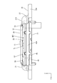
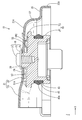
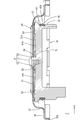
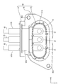
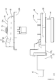
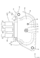
- top view of the opening sealing member in an embodiment Rear view Sectional view at position III-III in FIG. Sectional view at position IV-IV in FIG. Top view of connector Side view of the connector and the opening sealing member before assembly Plan view in a state after assembling the connector and the opening sealing member
- the opening sealing member 10 of the present embodiment is a connector 80 (an example of “electric device”) attached to a shield case of a device such as a motor or an inverter mounted on a vehicle.
- the opening 91 for work is closed.
- the Z direction is upward, with respect to the front and back direction, the X direction is forward, and with respect to the left and right direction, the Y direction is right.
- the connector 80 is connected to a terminal block (not shown) provided in the shield case as shown in FIGS.
- the connector 80 includes a conductive metal terminal 81, an electric wire 85 connected to the terminal 81, and a synthetic resin housing 90 that accommodates the terminal 81 and the terminal portion of the electric wire 85.
- the terminal 81 After the terminal 81 is connected to the electric wire 85, the terminal 81 is bent downward in an L shape, and further bent into an L shape at the lower end of the housing 90, thereby protruding into the opening 91 of the housing 90.
- the terminals 81 are insert-molded so that three terminals 81 are arranged in the left-right direction in the housing 90 and are connected to a mating terminal held on the terminal block.
- the housing 90 has a cylindrical housing main body 93 provided with an opening 91, a flat flange portion 95 protruding outward from the housing main body 93, and a rear portion of the housing main body 93, and an electric wire 85. And an electric wire holding portion 97 for holding the wire.
- the opening 91 opens in the vertical direction (vertical direction) and is an oval shape that is long in the left-right direction in plan view. And while the lower end part of the opening part 91 is fitted to a terminal block, the operation
- the electric wire holding portion 97 includes an integrated holding portion 97A that integrally holds a connection portion between the terminal 81 and the electric wire 85, and a cylindrical individual holding portion 97B that holds the electric wires 85 individually.
- the integral holding portion 97 ⁇ / b> A protrudes upward from the housing main body portion 93. Then, the electric wire 85 is drawn backward from the electric wire holding portion 97.
- the opening sealing member 10 includes a cover plate 20 and a plug body 40, and the cover plate 20 and the plug body 40 are fixed by a tap screw 70.
- the tap screw 70 includes a circular head 71, a circular ring portion 73 in which the diameter of the head 71 is increased, and a screw portion 75 capable of cutting a screw.
- the outer diameter of the ring portion 73 is larger than the diameter of the insertion hole 29 of the cover plate 20 to be described later, and is locked to the hole edge portion 29A of the insertion hole 29 to prevent it from coming off.
- the cover plate 20 is formed by pressing a metal plate such as a steel plate. As shown in FIGS. 1 and 2, the plate main body portion 21 covering the opening 91 and the electric wire holding portion 97 of the connector 80, and the connector 80.
- the attachment part 35 which covers the flange part 95 and the connection part 27 which connects between the edge part of the plate main-body part 21 and the attachment part 35 are provided.
- the connecting portion 27 connects the plate body portion 21 and the attachment portion 35 with an R shape and a vertical surface. And as the whole cover plate 20, it is carrying out the shape of the shallow shallow plate which makes the rectangular shape which can cover the opening part 91. As shown in FIG.
- the plate main body 21 covers the upper part of the integral holding part 97 ⁇ / b> A of the electric wire holding part 97 and opens the housing cover part 23 that opens to the rear, and the plug cover part 25 that covers the plug body 40. And.
- the housing cover part 23 is opened rearward, and the width dimension (dimension in the left-right direction) gradually increases toward the front.
- the plug body covering portion 25 is the same as the outer shape of the plug body 40 and has a slightly larger outer dimension.
- a circular insertion hole 29 through which a boss portion 55 of the plug body 40 to be described later can be inserted is provided in the central portion of the plug body covering section 25 in the left-right direction. The insertion hole 29 penetrates the plate body 21 in the thickness direction.
- a circular pin insertion hole 31 into which a positioning pin 57 of the plug body 40 to be described later can be inserted is provided on the right side of the insertion hole 29.
- the plate gradient PR is applied to the upper surface 21A of the plate body 21 so that the rear end is the highest and the front end is the lowest overall.
- the plate gradient PR partially differs in the degree of gradient, but the gradient of the portion of the plug body covering portion 25 in the plate main body portion 21 is constant.
- the front is always lower than the rear, and there is no horizontal state or a recessed portion.
- the water adhering to the plate main body 21 flows to the front side of the plate main body 21 due to the plate gradient PR. Then, the water that has reached the edge of the plate main body portion 21 falls on the connecting portion 27 and is washed away to the outside of the cover plate 20.
- the attachment part 35 covers the flange part 95 as shown in FIG.6 and FIG.7.
- the mounting portion 35 has substantially the same outer shape as the outer shape of the flange portion 95, the end portion of the mounting portion 35 is bent, and the side surface 35 ⁇ / b> A of the mounting portion 35 has a vertical dimension about the plate thickness of the flange portion 95. Thus, the flange portion 95 is completely covered.
- the mounting portion 35 is provided with a bolt hole 37 concentric with the bolt insertion hole 95 ⁇ / b> A of the flange portion 95.
- the plug body 40 is made of synthetic resin, and, as shown in FIGS. 3 and 4, a fitting portion 41 that can be fitted into the opening 91 (see FIG. 5), and an upper end portion of the fitting portion 41. It has the flat plate part 51 of the flat form provided continuously.
- the fitting portion 41 has an oval shape in plan view and has the same outer shape as the inner shape of the opening 91, and the outer dimension of the fitting portion 41 is the same as or slightly smaller than the inner dimension of the opening 91. .
- a seal mounting groove 43 is formed on the outer peripheral surface of the fitting portion 41 over the entire circumference.
- a seal member 45 having an oval ring shape is fitted in the seal mounting groove 43.
- a lip 45 ⁇ / b> A protrudes outward from the seal member 45, and the outer diameter of the lip 45 ⁇ / b> A is set slightly larger than the inner diameter of the opening 91.
- the flat plate portion 51 has a horizontally long oval shape, is substantially the same outer shape as the outer shape of the fitting portion 41, and is slightly larger.
- the outer dimension of the flat plate part 51 is larger than the inner dimension of the opening 91, and the entire flat plate part 51 is located above the opening 91. Then, the lower surface of the flat plate portion 51 comes into contact with the upper end hole edge portion 91 ⁇ / b> A (see FIG. 6) of the opening portion 91, and the plug body 40 is positioned at a predetermined position of the opening portion 91.
- contact portions 53 that contact the lower surface of the plate body portion 21 are provided at both ends of the flat plate portion 51 in the longitudinal direction (left-right direction).
- the contact portion 53 has a linear shape extending in the front-rear direction, and protrudes upward from the flat plate portion 51.
- the projecting dimension of the contact portion 53 from the flat plate portion 51 is constant in the front-rear direction.
- a boss portion 55 projects upward at the center position of the flat plate portion 51.
- the upper end portion of the boss portion 55 can be inserted with a predetermined clearance between the upper end portion of the boss portion 55 and the hole edge portion 29 ⁇ / b> A of the insertion hole 29 of the cover plate 20.
- the boss portion 55 is inserted into the insertion hole 29
- the height of the boss portion 55 is set so that the upper end surface of the boss portion 55 has a protruding dimension that slightly protrudes from the surface of the hole edge portion 29A of the insertion hole 29.
- hub part 55 has comprised the column shape and the pilot hole for screwing the tap screw 70 toward the back from the upper surface is provided.
- a round pin-shaped positioning pin 57 is formed to protrude to the right of the boss portion 55 of the flat plate portion 51.
- the positioning pin 57 can be inserted in a state having a predetermined clearance between the hole edge portion of the pin insertion hole 31 provided in the cover plate 20. Further, the positioning pin 57 has a protruding dimension that slightly protrudes from the surface of the cover plate 20.
- the upper surface 51 ⁇ / b> A of the flat plate portion 51 is attached to the first plug gradient HR ⁇ b> 1 applied in the longitudinal direction (left-right direction) of the flat plate portion 51 and in the short direction (front-rear direction).
- the first plug gradient HR1 is the highest at the left and right ends, and the position of the taper end line TL is the lowest.
- the taper end line TL extends straight in the front-rear direction (parallel to the X axis), and is provided on the right side of the boss portion 55 (positioning pin 57 side).
- the second plug gradient HR2 has the highest rear end and the lowest front end, and has the same gradient as the plate gradient PR of the opposing portion (plug cover portion 25) of the plate body 21. It has been.
- the water adhering to the flat plate portion 51 flows to the front side of the flat plate portion 51, and the water reaching the edge of the flat plate portion 51 flows outside the opening portion 91. Be dropped.
- the lower end position of the upper surface 51 ⁇ / b> A of the flat plate portion 51 is positioned above the upper end hole edge portion 91 ⁇ / b> A of the opening portion 91, and water that has flowed down from the upper surface 51 ⁇ / b> A of the flat plate portion 51 does not enter the opening portion 91.
- the opening sealing member 10 of the present embodiment has the above-described structure, and is assembled by the following procedure, for example.
- the seal member 45 is fitted into the seal mounting groove 43 of the plug body 40.
- the plug body 40 is attached to the lower side of the plate body portion 21 on the back surface (lower surface) side of the cover plate 20.
- the contact portion 53 of the flat plate portion 51 is brought into contact with the back surface (lower surface) of the plate main body portion 21 while the positioning pin 57 is inserted into the pin insertion hole 31 and the boss portion 55 is inserted into the insertion hole 29.
- the plate gradient PR of the plug cover portion 25 of the plate body 21 and the second plug gradient HR2 are substantially the same, the back surface of the plate body 21 and the contact portion 53 contact each other.
- the portion 53 abuts from the rear end to the front end.
- the tap screw 70 When the plug body 40 is applied to the back surface (rear surface) of the cover plate 20 in a normal posture, the tap screw 70 is fitted into the lower hole of the boss portion 55 and tightened. At this time, a female screw is cut into the prepared hole of the boss portion 55 by the screw portion 75 of the tap screw 70. Then, the tap screw 70 is screwed to a position where the ring portion 73 contacts the upper surface of the boss portion 55. At this time, the positioning pin 57 of the plug body 40 is fitted into the pin insertion hole 31 of the cover plate 20, so that the rotation of the plug body 40 with the screwing of the tap screw 70 is restricted.
- the plug body 40 is prevented from falling from the back surface (rear surface) of the cover plate 20 by the ring portion 73 coming into contact with the hole edge portion 29A of the insertion hole 29 and the upper surface of the boss portion 55. Moreover, the cover plate 20 will be in the state attached so that the movement along the axial direction of the boss
- the opening sealing member 10 When the opening sealing member 10 is assembled as described above, the opening sealing member 10 is attached to the opening 91 of the connector 80 as shown in FIG.
- the opening sealing member 10 When the opening sealing member 10 is arranged at a predetermined position and the cover plate 20 is pressed toward the connector 80 side, the plug body 40 is pushed into the opening 91 while the seal member 45 is crushed and deformed in the circumferential direction.
- the flat plate portion 51 comes into contact with the upper end hole edge portion 91A of the opening 91, the pushing operation is stopped. At this time, since the plug 40 is held in a state where it can move in all directions, the plug 40 is fitted while being centered with the opening 91.
- the mounting portion 35 of the cover plate 20 covers the flange portion 95 of the connector 80, and the bolt is passed through the bolt hole 37 and screwed into the case together with the bolt insertion hole 95 ⁇ / b> A of the connector 80. It is fixed together on the upper surface of the equipment case.
- the opening sealing member 10 is watered in a state where the opening 91 is closed by the opening sealing member 10. If the cover plate and the plug body are not inclined, the upper surfaces of the cover plate and the plug body that close the opening 91 opened in the vertical direction are in a horizontal state, and water remains. However, in this embodiment, the water applied to the upper surface 21A of the plate body 21 of the cover plate 20 flows down to the front side of the plate body 21 due to the plate gradient PR. Then, the water that has reached the edge of the plate main body portion 21 falls on the connecting portion 27 and is washed away to the outside of the cover plate 20. For this reason, it is possible to prevent water adhering to the cover plate 20 from staying on the cover plate 20 and corroding the cover plate 20.
- the infiltrated water flows to the front side of the flat plate portion 51 by the second plug gradient HR2 while being collected on the taper end line TL by the first plug gradient HR1 on the upper surface 51A of the flat plate portion 51 of the plug 40.
- the boss portion 55 since the positions in the longitudinal direction of the taper end line TL and the boss portion 55 are shifted, the boss portion 55 does not hinder the water collected on the taper end line TL from flowing forward. .
- the tapered end line TL on the locating pin 57 side of the boss portion 55 makes the gradient on the locating pin 57 side stiff, and even if the positioning pin 57 is present, water can easily flow. Then, the water that reaches the edge of the flat plate portion 51 by the two types of plug body gradients HR1 and HR2 is washed away to the outside of the opening 91. At this time, the lower end position of the upper surface 51 ⁇ / b> A of the flat plate portion 51 is located above the upper end hole edge portion 91 ⁇ / b> A of the opening 91, and the water that has flowed down from the upper surface 51 ⁇ / b> A of the flat plate portion 51 enters the opening 91. do not do. Since water that has entered between the plug 40 and the cover plate 20 is also discharged, it is possible to prevent the cover plate 20 from corroding and water from entering the opening 91.
- the water applied to the upper surface 21A of the plate main body 21 of the cover plate 20 and the water that has entered between the cover plate 20 and the plug body 40 are finally moved to the front side of the opening sealing member 10. run down. Therefore, it is only necessary to treat the water that has flowed down only on the front side. Moreover, since water is poured off to the front side, it can suppress that water splashes on the electric wire 85 extended to the rear side.
- the water applied to the cover plate 20 flows down from the cover plate 20 due to the plate gradient PR being applied to the upper surface 21A of the plate body 21 of the cover plate 20, and the water on the cover plate 20 is water. There is no risk of stagnation. Further, the water that has entered between the cover plate 20 and the plug body 40 also flows down from the top of the plug body 40 and flows outside the opening 91 because the plug body 40 is provided with plug body gradients HR1 and HR2. Since it is dropped, there is no possibility of staying between the plug 40 and the cover plate 20. Therefore, corrosion due to the invaded water can be suppressed.
- the plate gradient PR of the cover plate 20 is such that the rear end is high and the front end is low, but it may be reversed or may have a gradient in the longitudinal direction. Further, the gradient may be such that the central portion is raised and becomes lower toward the edge.
- the first plug body gradient HR1 of the plug body 40 is such that both ends are high and the taper end line TL is low.
- the gradient may be low.
- the taper end line TL is provided on the positioning pin 57 side of the boss portion 55, the taper end line TL may be on the opposite side or may overlap the boss portion 55.
- the second plug body gradient HR2 of the plug body 40 is such that the rear end is high and the front end is low. Further, the gradient may be such that the central portion is raised and becomes lower toward the edge. Furthermore, only one of the first plug body gradient HR1 and the second plug body gradient HR2 may be provided.
- attachment portion 35 is not inclined, but the flange portion 95 and the attachment portion 35 may be inclined.
- the mounting portion 35 covers the entire flange portion 95, but it may be provided only at the position in the bolt insertion hole 95A.
- the plate gradient PR of the cover plate 20 and the second plug body gradient HR2 of the plug body 40 are in the same direction and the opposite portions have the same angle, but in different directions. Alternatively, the opposing portions may have different angles.
- water is allowed to flow on the side opposite to the side on which the electric wires 85 extend, but it may not be on the opposite side.
- the opening 91 is provided in the housing 90 of the connector 80, but may be provided in a metal case or the like.
- the flat plate portion 51 having a larger outer dimension than the fitting portion 41 is provided.
- the outer diameter of the flat plate portion is the same as or smaller than the fitting portion 41. Also good.
- the lower end position of the upper surface of the plug body only needs to be positioned above the upper end surface of the opening 91.
Landscapes
- Connector Housings Or Holding Contact Members (AREA)
- Connections Arranged To Contact A Plurality Of Conductors (AREA)
Priority Applications (2)
| Application Number | Priority Date | Filing Date | Title |
|---|---|---|---|
| US16/603,215 US11011868B2 (en) | 2017-04-07 | 2018-04-02 | Opening sealing member and electrical device |
| CN201880023452.8A CN110495056B (zh) | 2017-04-07 | 2018-04-02 | 开口密封部件及电气设备 |
Applications Claiming Priority (2)
| Application Number | Priority Date | Filing Date | Title |
|---|---|---|---|
| JP2017-076928 | 2017-04-07 | ||
| JP2017076928A JP6709511B2 (ja) | 2017-04-07 | 2017-04-07 | 開口封止部材及び電気機器 |
Publications (1)
| Publication Number | Publication Date |
|---|---|
| WO2018186330A1 true WO2018186330A1 (ja) | 2018-10-11 |
Family
ID=63712182
Family Applications (1)
| Application Number | Title | Priority Date | Filing Date |
|---|---|---|---|
| PCT/JP2018/014069 Ceased WO2018186330A1 (ja) | 2017-04-07 | 2018-04-02 | 開口封止部材及び電気機器 |
Country Status (4)
| Country | Link |
|---|---|
| US (1) | US11011868B2 (enExample) |
| JP (1) | JP6709511B2 (enExample) |
| CN (1) | CN110495056B (enExample) |
| WO (1) | WO2018186330A1 (enExample) |
Families Citing this family (7)
| Publication number | Priority date | Publication date | Assignee | Title |
|---|---|---|---|---|
| JP6131996B2 (ja) * | 2015-11-10 | 2017-05-24 | 住友電装株式会社 | シールカバー |
| JP7259621B2 (ja) * | 2019-07-29 | 2023-04-18 | 住友電装株式会社 | ケース用の開口カバー装置 |
| JP7352163B2 (ja) * | 2019-10-15 | 2023-09-28 | 株式会社デンソー | カバーユニット |
| JP7191487B2 (ja) * | 2020-08-13 | 2022-12-19 | 矢崎総業株式会社 | コネクタ |
| JP7409295B2 (ja) * | 2020-12-18 | 2024-01-09 | 住友電装株式会社 | コネクタ |
| CN113784022B (zh) * | 2021-08-05 | 2023-05-26 | 鹏城实验室 | 水下摄像装置及水下机器人 |
| JP7771843B2 (ja) * | 2022-03-30 | 2025-11-18 | 住友電装株式会社 | 端子台 |
Citations (3)
| Publication number | Priority date | Publication date | Assignee | Title |
|---|---|---|---|---|
| JPH11126661A (ja) * | 1997-10-21 | 1999-05-11 | Yazaki Corp | スイッチ付きコネクタ装置 |
| JP2013026078A (ja) * | 2011-07-22 | 2013-02-04 | Yazaki Corp | コネクタ |
| JP2013149481A (ja) * | 2012-01-19 | 2013-08-01 | Sumitomo Wiring Syst Ltd | 機器用コネクタ |
Family Cites Families (8)
| Publication number | Priority date | Publication date | Assignee | Title |
|---|---|---|---|---|
| JPS56105272U (enExample) * | 1980-01-14 | 1981-08-17 | ||
| US4793819A (en) * | 1987-02-20 | 1988-12-27 | Sloan Valve Company | Over-the-road vehicle electrical connector with drain passage |
| JP3463632B2 (ja) * | 1999-12-02 | 2003-11-05 | 住友電装株式会社 | 電気接続箱 |
| JP2005229740A (ja) * | 2004-02-13 | 2005-08-25 | Sumitomo Wiring Syst Ltd | 自動車用電気接続箱 |
| JP4265990B2 (ja) * | 2004-04-12 | 2009-05-20 | 株式会社オートネットワーク技術研究所 | 電気接続箱 |
| JP5533774B2 (ja) * | 2010-06-07 | 2014-06-25 | 株式会社デンソー | 内燃機関用点火コイル |
| JP5645081B2 (ja) | 2011-05-10 | 2014-12-24 | 住友電装株式会社 | 車載用電気機器のシールカバー |
| JP2013054897A (ja) * | 2011-09-03 | 2013-03-21 | Sumitomo Wiring Syst Ltd | 防水コネクタ |
-
2017
- 2017-04-07 JP JP2017076928A patent/JP6709511B2/ja active Active
-
2018
- 2018-04-02 CN CN201880023452.8A patent/CN110495056B/zh active Active
- 2018-04-02 WO PCT/JP2018/014069 patent/WO2018186330A1/ja not_active Ceased
- 2018-04-02 US US16/603,215 patent/US11011868B2/en active Active
Patent Citations (3)
| Publication number | Priority date | Publication date | Assignee | Title |
|---|---|---|---|---|
| JPH11126661A (ja) * | 1997-10-21 | 1999-05-11 | Yazaki Corp | スイッチ付きコネクタ装置 |
| JP2013026078A (ja) * | 2011-07-22 | 2013-02-04 | Yazaki Corp | コネクタ |
| JP2013149481A (ja) * | 2012-01-19 | 2013-08-01 | Sumitomo Wiring Syst Ltd | 機器用コネクタ |
Also Published As
| Publication number | Publication date |
|---|---|
| US11011868B2 (en) | 2021-05-18 |
| JP2018181518A (ja) | 2018-11-15 |
| CN110495056A (zh) | 2019-11-22 |
| US20210083420A1 (en) | 2021-03-18 |
| CN110495056B (zh) | 2021-01-15 |
| JP6709511B2 (ja) | 2020-06-17 |
Similar Documents
| Publication | Publication Date | Title |
|---|---|---|
| WO2018186330A1 (ja) | 開口封止部材及び電気機器 | |
| JP5917013B2 (ja) | シールドコネクタ | |
| US7097498B2 (en) | Connector for apparatus | |
| CN112997365B (zh) | 电导体与电气设备连接件电接触的接触元件及其制造方法 | |
| CN110504587B (zh) | 连接器 | |
| JP5179524B2 (ja) | ケーブルコネクタ | |
| JP2003234144A (ja) | コネクタ | |
| US20240088613A1 (en) | Connector | |
| CN102576926A (zh) | 车顶安置天线装置 | |
| DE102018209129A1 (de) | Harz enthaltende Dichtung und wasserundurchlässige Verbindungseinrichtung | |
| JP5999448B2 (ja) | シールドコネクタ | |
| JP2006031962A (ja) | 機器用コネクタ | |
| ES2989102T3 (es) | Elemento de contacto y procedimiento para su producción | |
| JP2007026821A (ja) | シールド導電体 | |
| WO2022181751A1 (ja) | コネクタ | |
| JP2002373730A (ja) | モールドコネクタ | |
| JP6604512B2 (ja) | コネクタ | |
| JP2016174139A (ja) | 電気機器のシールカバー | |
| US9425574B2 (en) | Cast forming methods for making sealed conductors | |
| JP6781937B2 (ja) | ジョイントコネクタ | |
| JP2016178276A (ja) | 電気機器のシールカバー | |
| JP3908924B2 (ja) | 機器用シールドコネクタ | |
| JP4317483B2 (ja) | 機器用コネクタ | |
| JP2003264033A (ja) | モールドコネクタ | |
| WO2016147860A1 (ja) | 電気機器のシールカバー |
Legal Events
| Date | Code | Title | Description |
|---|---|---|---|
| 121 | Ep: the epo has been informed by wipo that ep was designated in this application |
Ref document number: 18780917 Country of ref document: EP Kind code of ref document: A1 |
|
| NENP | Non-entry into the national phase |
Ref country code: DE |
|
| 122 | Ep: pct application non-entry in european phase |
Ref document number: 18780917 Country of ref document: EP Kind code of ref document: A1 |