WO2018186133A1 - 運動案内装置 - Google Patents
運動案内装置 Download PDFInfo
- Publication number
- WO2018186133A1 WO2018186133A1 PCT/JP2018/009859 JP2018009859W WO2018186133A1 WO 2018186133 A1 WO2018186133 A1 WO 2018186133A1 JP 2018009859 W JP2018009859 W JP 2018009859W WO 2018186133 A1 WO2018186133 A1 WO 2018186133A1
- Authority
- WO
- WIPO (PCT)
- Prior art keywords
- path
- turn
- load
- carriage
- rolling
- Prior art date
- Legal status (The legal status is an assumption and is not a legal conclusion. Google has not performed a legal analysis and makes no representation as to the accuracy of the status listed.)
- Ceased
Links
Images



Classifications
-
- F—MECHANICAL ENGINEERING; LIGHTING; HEATING; WEAPONS; BLASTING
- F16—ENGINEERING ELEMENTS AND UNITS; GENERAL MEASURES FOR PRODUCING AND MAINTAINING EFFECTIVE FUNCTIONING OF MACHINES OR INSTALLATIONS; THERMAL INSULATION IN GENERAL
- F16C—SHAFTS; FLEXIBLE SHAFTS; ELEMENTS OR CRANKSHAFT MECHANISMS; ROTARY BODIES OTHER THAN GEARING ELEMENTS; BEARINGS
- F16C29/00—Bearings for parts moving only linearly
- F16C29/04—Ball or roller bearings
- F16C29/06—Ball or roller bearings in which the rolling bodies circulate partly without carrying load
- F16C29/0633—Ball or roller bearings in which the rolling bodies circulate partly without carrying load with a bearing body defining a U-shaped carriage, i.e. surrounding a guide rail or track on three sides
- F16C29/0669—Ball or roller bearings in which the rolling bodies circulate partly without carrying load with a bearing body defining a U-shaped carriage, i.e. surrounding a guide rail or track on three sides whereby the main body of the U-shaped carriage is an assembly of at least three major parts, e.g. an assembly of a top plate with two separate legs attached thereto in the form of bearing shoes
- F16C29/0671—Ball or roller bearings in which the rolling bodies circulate partly without carrying load with a bearing body defining a U-shaped carriage, i.e. surrounding a guide rail or track on three sides whereby the main body of the U-shaped carriage is an assembly of at least three major parts, e.g. an assembly of a top plate with two separate legs attached thereto in the form of bearing shoes with balls
-
- F—MECHANICAL ENGINEERING; LIGHTING; HEATING; WEAPONS; BLASTING
- F16—ENGINEERING ELEMENTS AND UNITS; GENERAL MEASURES FOR PRODUCING AND MAINTAINING EFFECTIVE FUNCTIONING OF MACHINES OR INSTALLATIONS; THERMAL INSULATION IN GENERAL
- F16C—SHAFTS; FLEXIBLE SHAFTS; ELEMENTS OR CRANKSHAFT MECHANISMS; ROTARY BODIES OTHER THAN GEARING ELEMENTS; BEARINGS
- F16C29/00—Bearings for parts moving only linearly
- F16C29/04—Ball or roller bearings
- F16C29/06—Ball or roller bearings in which the rolling bodies circulate partly without carrying load
- F16C29/0602—Details of the bearing body or carriage or parts thereof, e.g. methods for manufacturing or assembly
- F16C29/0609—Details of the bearing body or carriage or parts thereof, e.g. methods for manufacturing or assembly of the ends of the bearing body or carriage where the rolling elements change direction, e.g. end caps
-
- F—MECHANICAL ENGINEERING; LIGHTING; HEATING; WEAPONS; BLASTING
- F16—ENGINEERING ELEMENTS AND UNITS; GENERAL MEASURES FOR PRODUCING AND MAINTAINING EFFECTIVE FUNCTIONING OF MACHINES OR INSTALLATIONS; THERMAL INSULATION IN GENERAL
- F16C—SHAFTS; FLEXIBLE SHAFTS; ELEMENTS OR CRANKSHAFT MECHANISMS; ROTARY BODIES OTHER THAN GEARING ELEMENTS; BEARINGS
- F16C29/00—Bearings for parts moving only linearly
- F16C29/04—Ball or roller bearings
- F16C29/06—Ball or roller bearings in which the rolling bodies circulate partly without carrying load
- F16C29/0614—Ball or roller bearings in which the rolling bodies circulate partly without carrying load with a shoe type bearing body, e.g. a body facing one side of the guide rail or track only
- F16C29/0621—Ball or roller bearings in which the rolling bodies circulate partly without carrying load with a shoe type bearing body, e.g. a body facing one side of the guide rail or track only for supporting load in essentially two directions, e.g. by multiple points of contact or two rows of rolling elements
- F16C29/0623—Ball or roller bearings in which the rolling bodies circulate partly without carrying load with a shoe type bearing body, e.g. a body facing one side of the guide rail or track only for supporting load in essentially two directions, e.g. by multiple points of contact or two rows of rolling elements with balls
-
- F—MECHANICAL ENGINEERING; LIGHTING; HEATING; WEAPONS; BLASTING
- F16—ENGINEERING ELEMENTS AND UNITS; GENERAL MEASURES FOR PRODUCING AND MAINTAINING EFFECTIVE FUNCTIONING OF MACHINES OR INSTALLATIONS; THERMAL INSULATION IN GENERAL
- F16C—SHAFTS; FLEXIBLE SHAFTS; ELEMENTS OR CRANKSHAFT MECHANISMS; ROTARY BODIES OTHER THAN GEARING ELEMENTS; BEARINGS
- F16C29/00—Bearings for parts moving only linearly
- F16C29/04—Ball or roller bearings
- F16C29/045—Ball or roller bearings having rolling elements journaled in one of the moving parts
- F16C29/046—Ball or roller bearings having rolling elements journaled in one of the moving parts with balls journaled in pockets
-
- F—MECHANICAL ENGINEERING; LIGHTING; HEATING; WEAPONS; BLASTING
- F16—ENGINEERING ELEMENTS AND UNITS; GENERAL MEASURES FOR PRODUCING AND MAINTAINING EFFECTIVE FUNCTIONING OF MACHINES OR INSTALLATIONS; THERMAL INSULATION IN GENERAL
- F16C—SHAFTS; FLEXIBLE SHAFTS; ELEMENTS OR CRANKSHAFT MECHANISMS; ROTARY BODIES OTHER THAN GEARING ELEMENTS; BEARINGS
- F16C29/00—Bearings for parts moving only linearly
- F16C29/04—Ball or roller bearings
- F16C29/06—Ball or roller bearings in which the rolling bodies circulate partly without carrying load
- F16C29/0633—Ball or roller bearings in which the rolling bodies circulate partly without carrying load with a bearing body defining a U-shaped carriage, i.e. surrounding a guide rail or track on three sides
- F16C29/0635—Ball or roller bearings in which the rolling bodies circulate partly without carrying load with a bearing body defining a U-shaped carriage, i.e. surrounding a guide rail or track on three sides whereby the return paths are provided as bores in a main body of the U-shaped carriage, e.g. the main body of the U-shaped carriage is a single part with end caps provided at each end
- F16C29/0638—Ball or roller bearings in which the rolling bodies circulate partly without carrying load with a bearing body defining a U-shaped carriage, i.e. surrounding a guide rail or track on three sides whereby the return paths are provided as bores in a main body of the U-shaped carriage, e.g. the main body of the U-shaped carriage is a single part with end caps provided at each end with balls
- F16C29/064—Ball or roller bearings in which the rolling bodies circulate partly without carrying load with a bearing body defining a U-shaped carriage, i.e. surrounding a guide rail or track on three sides whereby the return paths are provided as bores in a main body of the U-shaped carriage, e.g. the main body of the U-shaped carriage is a single part with end caps provided at each end with balls with two rows of balls, one on each side of the rail
-
- F—MECHANICAL ENGINEERING; LIGHTING; HEATING; WEAPONS; BLASTING
- F16—ENGINEERING ELEMENTS AND UNITS; GENERAL MEASURES FOR PRODUCING AND MAINTAINING EFFECTIVE FUNCTIONING OF MACHINES OR INSTALLATIONS; THERMAL INSULATION IN GENERAL
- F16C—SHAFTS; FLEXIBLE SHAFTS; ELEMENTS OR CRANKSHAFT MECHANISMS; ROTARY BODIES OTHER THAN GEARING ELEMENTS; BEARINGS
- F16C29/00—Bearings for parts moving only linearly
- F16C29/04—Ball or roller bearings
- F16C29/06—Ball or roller bearings in which the rolling bodies circulate partly without carrying load
- F16C29/0633—Ball or roller bearings in which the rolling bodies circulate partly without carrying load with a bearing body defining a U-shaped carriage, i.e. surrounding a guide rail or track on three sides
- F16C29/0669—Ball or roller bearings in which the rolling bodies circulate partly without carrying load with a bearing body defining a U-shaped carriage, i.e. surrounding a guide rail or track on three sides whereby the main body of the U-shaped carriage is an assembly of at least three major parts, e.g. an assembly of a top plate with two separate legs attached thereto in the form of bearing shoes
- F16C29/0673—Ball or roller bearings in which the rolling bodies circulate partly without carrying load with a bearing body defining a U-shaped carriage, i.e. surrounding a guide rail or track on three sides whereby the main body of the U-shaped carriage is an assembly of at least three major parts, e.g. an assembly of a top plate with two separate legs attached thereto in the form of bearing shoes with rollers
-
- F—MECHANICAL ENGINEERING; LIGHTING; HEATING; WEAPONS; BLASTING
- F16—ENGINEERING ELEMENTS AND UNITS; GENERAL MEASURES FOR PRODUCING AND MAINTAINING EFFECTIVE FUNCTIONING OF MACHINES OR INSTALLATIONS; THERMAL INSULATION IN GENERAL
- F16C—SHAFTS; FLEXIBLE SHAFTS; ELEMENTS OR CRANKSHAFT MECHANISMS; ROTARY BODIES OTHER THAN GEARING ELEMENTS; BEARINGS
- F16C33/00—Parts of bearings; Special methods for making bearings or parts thereof
- F16C33/30—Parts of ball or roller bearings
- F16C33/38—Ball cages
- F16C33/3837—Massive or moulded cages having cage pockets surrounding the balls, e.g. machined window cages
-
- F—MECHANICAL ENGINEERING; LIGHTING; HEATING; WEAPONS; BLASTING
- F16—ENGINEERING ELEMENTS AND UNITS; GENERAL MEASURES FOR PRODUCING AND MAINTAINING EFFECTIVE FUNCTIONING OF MACHINES OR INSTALLATIONS; THERMAL INSULATION IN GENERAL
- F16C—SHAFTS; FLEXIBLE SHAFTS; ELEMENTS OR CRANKSHAFT MECHANISMS; ROTARY BODIES OTHER THAN GEARING ELEMENTS; BEARINGS
- F16C29/00—Bearings for parts moving only linearly
- F16C29/04—Ball or roller bearings
- F16C29/06—Ball or roller bearings in which the rolling bodies circulate partly without carrying load
- F16C29/0633—Ball or roller bearings in which the rolling bodies circulate partly without carrying load with a bearing body defining a U-shaped carriage, i.e. surrounding a guide rail or track on three sides
- F16C29/0635—Ball or roller bearings in which the rolling bodies circulate partly without carrying load with a bearing body defining a U-shaped carriage, i.e. surrounding a guide rail or track on three sides whereby the return paths are provided as bores in a main body of the U-shaped carriage, e.g. the main body of the U-shaped carriage is a single part with end caps provided at each end
- F16C29/0638—Ball or roller bearings in which the rolling bodies circulate partly without carrying load with a bearing body defining a U-shaped carriage, i.e. surrounding a guide rail or track on three sides whereby the return paths are provided as bores in a main body of the U-shaped carriage, e.g. the main body of the U-shaped carriage is a single part with end caps provided at each end with balls
- F16C29/0642—Ball or roller bearings in which the rolling bodies circulate partly without carrying load with a bearing body defining a U-shaped carriage, i.e. surrounding a guide rail or track on three sides whereby the return paths are provided as bores in a main body of the U-shaped carriage, e.g. the main body of the U-shaped carriage is a single part with end caps provided at each end with balls with four rows of balls
- F16C29/0647—Ball or roller bearings in which the rolling bodies circulate partly without carrying load with a bearing body defining a U-shaped carriage, i.e. surrounding a guide rail or track on three sides whereby the return paths are provided as bores in a main body of the U-shaped carriage, e.g. the main body of the U-shaped carriage is a single part with end caps provided at each end with balls with four rows of balls with load directions in X-arrangement
-
- F—MECHANICAL ENGINEERING; LIGHTING; HEATING; WEAPONS; BLASTING
- F16—ENGINEERING ELEMENTS AND UNITS; GENERAL MEASURES FOR PRODUCING AND MAINTAINING EFFECTIVE FUNCTIONING OF MACHINES OR INSTALLATIONS; THERMAL INSULATION IN GENERAL
- F16C—SHAFTS; FLEXIBLE SHAFTS; ELEMENTS OR CRANKSHAFT MECHANISMS; ROTARY BODIES OTHER THAN GEARING ELEMENTS; BEARINGS
- F16C33/00—Parts of bearings; Special methods for making bearings or parts thereof
- F16C33/30—Parts of ball or roller bearings
- F16C33/37—Loose spacing bodies
- F16C33/3706—Loose spacing bodies with concave surfaces conforming to the shape of the rolling elements, e.g. the spacing bodies are in sliding contact with the rolling elements
Definitions
- the present invention relates to a motion guide device that guides the movement of a table or the like.
- This type of motion guide device includes a raceway member attached to a base or the like, and a carriage attached to the raceway member via a rolling element such as a ball or a roller so as to be relatively movable and attached to a table or the like.
- the rolling member is formed with a rolling element rolling portion on which the rolling element rolls.
- the carriage is formed with a load rolling element rolling portion facing the rolling element rolling portion. When the carriage moves relative to the raceway member, the rolling element rolls along a load path between the rolling element rolling part and the load rolling element rolling part.
- the carriage is provided with a circulation path for circulating the rolling elements.
- the circulation path includes a load path, a return path parallel to the load path, and a substantially U-shaped turn path connected to the load rolling element rolling portion and the return path, and has a track shape.
- the circulation path is arranged in one plane. Then, in the front view of the carriage (viewed in the relative movement direction of the carriage), the circulation path is arranged in the direction of the contact angle of the rolling elements (see Patent Document 1). This is to ensure the contact width between the rolling element and the rolling element rolling part and the contact width between the rolling element and the loaded rolling element rolling part.
- the conventional motion guide device has the problem that the layout of the circulation path is limited as described above and the carriage becomes larger. In order to make the carriage compact, if the circulation path is shifted from the direction of the contact angle of the rolling element in the front view of the carriage, the contact width of the rolling element is sacrificed, and the rated load and allowable load of the motion guide device are reduced. There is a problem.
- an object of the present invention is to provide a motion guide device that can prevent the rated load and the allowable load from being reduced and can make the carriage compact.
- an aspect of the present invention includes a raceway member having a rolling element rolling part, a loaded rolling element rolling part facing the rolling element rolling part, and the loaded rolling element rolling part.
- a motion guide device comprising a load path, the return path, and a plurality of rolling elements arranged so as to be able to circulate in the turn path, in a side view as viewed from the direction in which the load path and the return path overlap, This is a motion guide device in which at least a part of the turn path is curved.
- the present invention it is possible to increase the degree of freedom in designing the layout of the circulation path without sacrificing the contact width of the rolling elements. For this reason, it can prevent that a rated load and an allowable load become small, and can make a carriage compact.
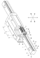
- FIG. 1 is a perspective view (including a partial cross section) of a motion guide device according to a first embodiment of the present invention. It is a front view of the exercise
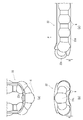
- FIG. 5A is a three-side view of a circulation path (FIG. 5A is a plan view, FIG. 5B is a front view, and FIG. 5C is a side view).
- FIG. 6 is a view showing a retainer band (FIG. 6A is a plan view and FIG. 6B is a side view).
- FIG. 8 is a three-side view (FIG. 8A is a plan view, FIG. 8B is a front view, and FIG. 8C is a side view) of a retainer band opened in a C shape.
- FIG. 10 (a) is a plan view
- FIG. 10 (b) is a front view
- FIG. 10 (c) is a side view.
- Fig. 11 is a three-side view of the retainer band opened in a letter C shape (Fig. 11 (a) is a plan view, Fig. 11 (b) is a front view, and Fig. 11 (c) is a side view).
- FIG. 1 is a perspective view (including a partial cross-sectional view) of the motion guide device.
- FIG. 2 is a front view of the motion guide apparatus with the end plate 5 removed (as viewed in the relative movement direction of the carriage 2).
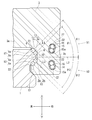
- FIG. 3 is a cross-sectional view of the motion guide device orthogonal to the relative movement direction of the carriage 2.
- the motion guide device is arranged on a horizontal plane, and the direction when the motion guide device is viewed from the front (as viewed in the relative movement direction of the carriage 2), that is, up and down, left and right in FIGS.
- the configuration of the motion guide device will be described using front and rear.
- the arrangement of the motion guide device is not limited to this.
- the motion guide device of the first embodiment is a linear guide.
- Reference numeral 1 is a guide rail as a track member
- reference numeral 2 is a carriage
- reference numeral 6 is a ball as a rolling element.
- Two track-like circulation paths 7 are provided on the left and right sides of the carriage 2. There are a total of four circulation paths 7.
- two circulation lines 7 are provided with two ball rows 6a and 6b, and a total of eight ball rows 6a and 6b are provided.
- the guide rail 1 is long in the front-rear direction. On the left and right sides of the upper portion of the guide rail 1, protrusions 11 projecting in the left-right direction are formed. On the guide rail 1, ball rolling parts 12 as upper and lower rolling element rolling parts are formed on the left and right sides so as to sandwich the protrusion 11. Two ball rolling grooves 1 a are formed in each ball rolling portion 12, and a total of eight ball rolling grooves 1 a are formed in the guide rail 1.
- the ball rolling groove 1a is a circular arc groove whose cross section is a single circular arc.
- the guide rail 1 is provided with a through hole 1b for attaching the guide rail 1 to a base or the like.
- the carriage 2 includes a carriage body 3, inner plates 4 that are attached to both end faces of the carriage body 3 in the relative movement direction, and end plates 5 that are attached to both end faces of the carriage body 3 so as to cover the inner plate 4. .
- the carriage body 3 has an inverted U shape when viewed from the front (FIG. 3 shows only the right half, but the carriage body 3 is bilaterally symmetric), and the center facing the upper surface of the guide rail 1. It has the part 3a and the right and left sleeve part 3b which opposes the side surface of the guide rail 1.
- two upper and lower load ball rolling portions 13 facing the ball rolling portion 12 of the guide rail 1 are formed.
- Two load ball rolling grooves 3 c are formed in each load ball rolling portion 13, and a total of eight load ball rolling grooves 3 c are formed in the carriage body 3.
- the loaded ball rolling groove 3c is a circular arc groove whose cross section is a single circular arc.
- the load path C1 is formed between the load ball rolling portion 13 of the carriage body 3 and the ball rolling portion 12 of the guide rail 1.
- the angle formed by the direction of the contact angle L1 of the ball 6 in the upper load path C1 and the horizontal direction L2 is ⁇ 1.
- the angle formed between the direction of the contact angle L3 of the ball 6 in the lower load path C1 and the horizontal direction L2 is ⁇ 2.
- the directions of the contact angles L1 and L3 are directions of a line connecting the contact point between the ball 6 and the ball rolling groove 1a and the contact point between the ball 6 and the load ball rolling groove 3c.
- ⁇ 1 and ⁇ 2 are appropriately determined according to the direction of the load that the carriage 2 receives. If ⁇ 1 and ⁇ 2 are set to 45 °, for example, the carriage 2 can receive loads in four directions, up, down, left, and right.
- the ball rolling groove 1a and the loaded ball rolling groove 3c can be formed as Gothic arch grooves.
- the direction of the contact angle is a direction of a line connecting the bottom of the Gothic arch groove of the ball rolling groove 1a and the bottom of the Gothic arch groove of the loaded ball rolling groove 3c.
- a through hole 14 is formed in the carriage body 3 in parallel with the load ball rolling portion 13.
- a return path constituting member 15 constituting the return path C2 is inserted into the through hole 14.
- a total of four return paths C ⁇ b> 2 are provided on the left and right sleeve portions 3 b of the carriage body 3.
- the return path C2 is disposed at a position shifted from the direction of the contact angle L1, L3 of the ball 6 toward the horizontal direction L2.
- the inner plate 4 has an inverted U shape when viewed from the front, a central portion 4 a facing the top surface of the guide rail 1, and a pair of left and right sleeves facing the side surface of the guide rail 1. Part 4b.
- the inner peripheral side of a substantially U-shaped turn path C3 that connects the load path C1 and the return path C2 is formed on the sleeve 4b of the inner plate 4.
- the end plate 5 also has an inverted U shape when viewed from the front, and includes a central portion 5 a that faces the upper surface of the guide rail 1 and a pair of left and right sleeve portions 5 b that face the side surfaces of the guide rail 1.
- a substantially U-shaped turn path C ⁇ b> 3 is formed on the sleeve portion 5 b of the end plate 5.
- a total of four turn paths C3 are provided on the left and right sleeve portions 4b, 5b of the inner plate 4 and the end plate 5 in two.
- the end plate 5 and the inner plate 4 are attached to the carriage body 3 by bolts 21 (see FIG. 2).
- Bolts for holes are formed in the end plate 5 and the inner plate 4.
- the end plate 5 and the inner plate 4 are attached to the carriage body 3 by passing the bolt 21 through the through holes of the end plate 5 and the inner plate 4 and screwing the bolt 21 into the carriage body 3.
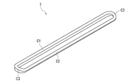
- FIG. 4 shows a perspective view of the circulation path 7, and FIG.
- the straight load path C1, the straight return path C2, and the pair of substantially U-shaped turn paths C3 constitute a track-shaped circulation path 7.
- a total of four circulation paths 7 are provided on the left and right sleeve portions of the carriage 2, two in the upper and lower directions (see FIG. 2).
- the load path C1 is formed between the guide rail 1 and the carriage body 3.
- the return path C ⁇ b> 2 is formed in the carriage body 3.
- the turn path C3 is formed between the inner plate 4 and the end plate 5.
- the circulation path 7 since the two ball rows 6a and 6b are arranged in the circulation path 7, the circulation path 7 has a shape in which the ball circulation paths having a substantially circular cross section are stacked in two upper and lower stages.
- the turn path C3 is curved in a side view as viewed from the direction in which the load path C1 and the return path C2 overlap.
- a deviation A indicating the degree of curvature occurs between the center of the turn path C3 (the center of the turn path C3 in the moving direction of the ball 6) and the load path C1 and the return path C2.
- the turn path C3 is curved in a convex shape.
- the side view seen from the direction in which the load path C1 and the return path C2 overlap each other means that the upper load path C1 and the return path C2 in FIG. 3 are seen from the diagonally upper right direction (the direction of the arrow V1). This means that the lower load path C1 and return path C2 are viewed from the diagonally lower right direction (the direction of arrow V2).
- the upper turn path C3 is curved upward and the lower turn path C3 is curved downward.
- the upper turn path C3 and the lower turn path C3 are farthest from each other in the center in the left-right direction (width direction).
- a mounting bolt 21 for the end plate 5 is disposed between the central portion in the width direction of the upper turn path C3 and the central portion in the width direction of the lower turn path C3.
- the retainer band 22 includes a band-shaped band body 22 a and a plurality of spacers 22 b that are interposed between the balls 6 and formed integrally with the band body 22 a.
- the retainer band 22 holds two ball rows 6a and 6b. One ball row 6a and the other ball row 6b are out of phase by a half pitch.
- the carriage body 3 is provided with holding portions 23a, 23b, and 23c for holding and guiding the retainer band 22 in the load path C1.
- Reference numeral 5 in FIG. 2 denotes an end plate on the back side.
- the return path constituting member 15 of the carriage body 3 is provided with a guide groove 15a for guiding the retainer band 22 in the return path C2. Between the inner plate 4 and the end plate 5, a guide groove for guiding the retainer band 22 in the turn path C3 is provided.
- the retainer band 22 in the load path C ⁇ b> 1 and the retainer band 22 in the return path C ⁇ b> 2 open in a C shape in a cross-sectional view of the carriage 2.
- the retainer band 22 is arranged perpendicular to the direction of the contact angles L1 and L3 in order to secure the contact width of the ball 6 in the load path C1, and the return path C2 is made to be the contact angle in order to make the carriage 2 compact. This is because they are arranged at positions shifted from the directions of L1 and L3 in the horizontal direction L2.
- FIG. 7 shows a perspective view of the retainer band 22 opened in a letter C shape
- FIG. 8 shows a three-side view of the retainer band 22 opened in a letter C shape.
- the turn portion 22c of the retainer band 22 opens as shown in the side view of FIG. It naturally curves in the direction P. This state is a reasonable state where the generated stress is the smallest.
- the turn path C 3 is also curved in the shape of a letter C according to the curvature of the retainer band 22, and the deviation A of the turn path C 3 is caused by the turn portion of the retainer band 22. It corresponds to the deviation A of 22c.
- the motion guide device of the present embodiment the following effects can be obtained. Since the turn path C3 is curved in a side view where the load path C1 and the return path C2 overlap (see FIG. 5C), the contact width between the ball 6 and the ball rolling groove 1a, and the ball 6 and the load ball rolling
- the return path C2 can be arranged at a position shifted in the horizontal direction L2 from the direction of the contact angles L1 and L3 of the ball 6 without sacrificing the contact width with the running groove 3c (see FIG. 3). For this reason, it can prevent that a rated load and an allowable load become small, and can make the carriage 2 compact. Moreover, in the motion guide device of the same size, the rated load and the allowable load can be increased.
- the retainer band 22 is opened in a letter C shape, and the turn path C3 is curved in a side view in a direction P where the retainer band 22 is opened in a letter C shape (see FIGS. 5 (c) and 8 (c)).
- the curve of the turn path C3 can be matched with the curve of the retainer band 22, and the retainer band 22 can be turned without difficulty.
- the retainer band 22 holds the two or more ball rows 6a and 6b, the posture of the retainer band 22 opened in a letter C shape in the load path C1 and the return path C2 can be stabilized (see FIG. 3). It is possible to prevent or reduce the retainer band 22 from sliding on the guide groove.
- the upper turn path C3 curves upward and the lower turn path C3 curves downward (see FIG. 2), so that the motion guide device can be made more compact. .
- the bolts for attaching the end plate 5 between these center parts 21 can be arranged, and the bolt 21 can be made larger.
- the end plate 5 is made of a resin-made substantially plate shape in terms of productivity and functionality. Since the end plate 5 is fixed to the metal carriage body 3 with a limited number of bolts 21, the portion of the end plate 5 away from the position of the bolt 21 may have poor adhesion to the carriage body 3. .
- the bolt 21 'for attaching the conventional end plate 5 has to be arranged at a position biased with respect to the turn path C3, but by arranging the bolt 21 at the center in the left-right direction of the turn path C3.
- the adhesion between the end plate 5 and the carriage body 3 can be improved.
- FIG. 9 shows a motion guide apparatus according to a second embodiment of the present invention.
- FIG. 9 shows a front view of the motion guide apparatus with the end plate 5 removed.
- the motion guide apparatus also has a guide rail 1 as a track member, a carriage 2 assembled to the guide rail 1 so as to be relatively movable, and a rolling element interposed between the guide rail 1 and the carriage 2. And a ball 6.
- Two track-like circulation paths 7 are provided on the left and right sides of the carriage 2.
- the second embodiment is different from the first embodiment in that one ball row is arranged in the circulation path 7.
- One ball rolling groove 1a is formed in each ball rolling portion of the guide rail 1, and a total of four ball rolling grooves 1a are formed in the guide rail 1.
- Each load ball rolling part of the carriage body 3 is formed with one load ball rolling groove, and the carriage body 3 is formed with a total of four load ball rolling grooves.
- Other configurations of the guide rail 1, the carriage body 3, and the inner plate 4 are substantially the same as those in the first embodiment, and therefore, the same reference numerals are given and description thereof is omitted.
- FIG. 10 shows a three-sided view of the circulation path 7.
- a straight load path C1, a straight return path C2, and a pair of substantially U-shaped turn paths C3 form a track-shaped circulation path 7.
- the turn path C3 is curved in a side view as viewed from the direction in which the load path C1 and the return path C2 overlap.
- a deviation B indicating the degree of curvature occurs between the center of the turn path C3 (the center of the turn path C3 in the moving direction of the ball 6) and the load path C1 and the return path C2.
- the turn path C3 is curved in a convex shape.
- the upper turn path C3 is curved upward and the lower turn path C3 is curved downward.
- the upper turn path C3 and the lower turn path C3 are farthest from each other in the center in the left-right direction (width direction).
- a mounting bolt 21 for the end plate 5 is disposed between the central portion in the width direction of the upper turn path C3 and the central portion in the width direction of the lower turn path C3.
- FIG. 11 shows a three-sided view of the retainer band opened in a C shape.
- the turn portion 22 c of the retainer band 22 opens as shown in the side view of FIG. It curves naturally toward the direction P.
- a deviation B indicating the degree of curvature is generated between the center of the turn portion 22c of the retainer band 22 (the center in the length direction of the turn portion 22c of the retainer band 22) and the straight portion 22d that is opened in a C shape.
- FIG. 11 shows a three-sided view of the retainer band opened in a C shape.
- the turn path C 3 is also curved in the shape of a letter C according to the curvature of the retainer band 22, and the deviation B of the turn path C 3 is the turn part 22 c of the retainer band 22. This corresponds to the deviation B.
- the turn path C3 is curved in a side view where the load path C1 and the return path C2 overlap (see FIG. 10C), so that the contact width between the ball 6 and the ball rolling groove 1a, Further, the return path C2 can be arranged at a position shifted in the horizontal direction from the direction of the contact angle of the ball 6 without sacrificing the contact width between the ball 6 and the loaded ball rolling groove (see FIG. 9). For this reason, it can prevent making the rated load and allowable load of a motion guide apparatus small, and can make the carriage 2 compact.
- the curve of the turn path C3 can be matched with the curve of the retainer band 22, and the retainer band 22 can be turned without difficulty.
- the retainer band that holds the ball can be omitted. That is, the present invention can also be applied to a total ball type motion guide device.
- the entire turn path is curved in a side view, but only a part of the turn path can be curved.
- Rollers can be used as rolling elements instead of balls.
- the present invention can be applied to a ball spline in addition to a linear guide.
- SYMBOLS 1 Guide rail (track member), 1a ... Ball rolling groove (rolling body rolling part), 2 ... Carriage, 3 ... Carriage main body, 3c ... Loaded ball rolling groove (loaded rolling element rolling part), 4 ... Inner plate, 5 ... End plate, 6 ... Ball (rolling element), 6a, 6b ... Ball train, 7 ... Circulation path, 12 ... Ball rolling part (rolling element rolling part), 13 ... Loaded ball rolling part ( Load rolling element rolling part), 21 ... bolt, 22 ... retainer band, C1 ... load path, C2 ... return path, C3 ... turn path
Landscapes
- Engineering & Computer Science (AREA)
- General Engineering & Computer Science (AREA)
- Mechanical Engineering (AREA)
- Bearings For Parts Moving Linearly (AREA)
Abstract
定格荷重及び許容荷重を小さくすることなく、キャリッジをコンパクトにすることができる運動案内装置を提供する。 運動案内装置は、軌道部材(1)と、軌道部材(1)に沿って移動するキャリッジ(2)と、を備える。キャリッジ(2)の循環路(7)が、負荷路(C1)、負荷路(C1)に平行な戻し路(C2)、及び負荷路(C1)と戻し路(C2)に繋がる略U字状のターン路(C3)から構成される。負荷路(C1)と戻し路(C2)とが重なる方向から見た側面視において、ターン路(C3)の少なくとも一部が湾曲する。
Description
本発明は、テーブル等が運動するのを案内する運動案内装置に関する。
この種の運動案内装置は、ベース等に取り付けられる軌道部材と、軌道部材にボール、ローラ等の転動体を介して相対移動可能に組み付けられ、テーブル等に取り付けられるキャリッジと、を備える。軌道部材には、転動体が転走する転動体転走部が形成される。キャリッジには、転動体転走部に対向する負荷転動体転走部が形成される。キャリッジが軌道部材に対して相対移動すると、転動体が転動体転走部と負荷転動体転走部との間の負荷路を転がり運動する。
キャリッジには、転動体を循環させるための循環路が設けられる。循環路は、負荷路と、負荷路に平行な戻し路と、負荷転動体転走部と戻し路とに繋がる略U字状のターン路と、から構成され、トラック状である。キャリッジが軌道部材に対して相対移動すると、転動体が循環路を循環する。
従来の運動案内装置において、循環路は一平面内に配置される。そして、キャリッジの正面視(キャリッジの相対移動方向視)において、循環路は転動体の接触角の方向に配置される(特許文献1参照)。転動体と転動体転走部との接触幅、及び転動体と負荷転動体転走部との接触幅を確保するためである。
しかし、従来の運動案内装置にあっては、循環路のレイアウトに上記の制約があり、キャリッジが大型化するという課題がある。キャリッジをコンパクトにするために、キャリッジの正面視において、転動体の接触角の方向から循環路をずらすと、転動体の接触幅が犠牲になり、運動案内装置の定格荷重及び許容荷重が小さくなるという課題がある。
そこで本発明は、定格荷重及び許容荷重が小さくなるのを防止でき、キャリッジをコンパクトにすることができる運動案内装置を提供することを目的とする。
上記課題を解決するために、本発明の一態様は、転動体転走部を有する軌道部材と、前記転動体転走部に対向する負荷転動体転走部、前記負荷転動体転走部に平行な戻し路、及び前記負荷転動体転走部と前記戻し路とに繋がる略U字状のターン路を有するキャリッジと、前記転動体転走部と前記負荷転動体転走部との間の負荷路、前記戻し路、及び前記ターン路に循環可能に配列される複数の転動体と、を備える運動案内装置において、前記負荷路と前記戻し路とが重なる方向から見た側面視において、前記ターン路の少なくとも一部が湾曲する運動案内装置である。
本発明によれば、転動体の接触幅を犠牲にすることなく、循環路の配置設計の自由度を増すことができる。このため、定格荷重及び許容荷重が小さくなるのを防止でき、キャリッジをコンパクトにすることができる。
以下、添付図面に基づいて、本発明の実施形態の運動案内装置を説明する。ただし、本発明の運動案内装置は種々の形態で具体化することができ、本明細書に記載される実施形態に限定されるものではない。本実施形態は、明細書の開示を十分にすることによって、当業者が発明の範囲を十分に理解できるようにする意図をもって提供されるものである。
(第1の実施形態)
(第1の実施形態)
図1ないし図3は、本発明の第1の実施形態の運動案内装置を示す。図1は、運動案内装置の斜視図(一部断面図を含む)である。図2は、エンドプレート5を取り外した状態の運動案内装置の正面図(キャリッジ2の相対移動方向視)である。図3は、キャリッジ2の相対移動方向に直交する運動案内装置の断面図である。
なお、以下の説明において、説明の便宜上、運動案内装置を水平面に配置し、運動案内装置を正面視(キャリッジ2の相対移動方向視)したときの方向、すなわち図1、図2の上下、左右、前後を用いて運動案内装置の構成を説明する。もちろん、運動案内装置の配置はこれに限られるものではない。
図1に示すように、第1の実施形態の運動案内装置はリニアガイドである。符号1は軌道部材としての案内レール、符号2はキャリッジ、符号6は転動体としてのボールである。キャリッジ2の左右には、上下2つのトラック状の循環路7が設けられる。循環路7は合計4つである。第1の実施形態では、低ウェービングと高剛性を実現するために、各循環路7に2つのボール列6a,6bを設け、合計8つのボール列6a,6bを設ける。
案内レール1は、前後方向に長い。案内レール1の上部の左右には、左右方向に突出する突条11が形成される。案内レール1には、突条11を挟むようにその左右に上下2つの転動体転走部としてのボール転走部12が形成される。各ボール転走部12には2条のボール転走溝1aが形成され、案内レール1には合計8条のボール転走溝1aが形成される。ボール転走溝1aは、断面が単一の円弧からなるサーキュラーアーク溝である。案内レール1には、案内レール1をベース等に取り付けるための通し孔1bが開けられる。
キャリッジ2は、キャリッジ本体3と、キャリッジ本体3の相対移動方向の両端面に取り付けられるインナープレート4と、キャリッジ本体3の両端面にインナープレート4を覆うように取り付けられるエンドプレート5と、を備える。
図3に示すように、キャリッジ本体3は、正面視において逆U字状であり(図3は右半分のみ示すが、キャリッジ本体3は左右対称である)、案内レール1の上面に対向する中央部3aと、案内レール1の側面に対向する左右の袖部3bと、を有する。キャリッジ本体3の左右の袖部3bには、案内レール1のボール転走部12に対向する上下2つの負荷ボール転走部13が形成される。各負荷ボール転走部13には2条の負荷ボール転走溝3cが形成され、キャリッジ本体3には合計8条の負荷ボール転走溝3cが形成される。負荷ボール転走溝3cは、断面が単一の円弧からなるサーキュラーアーク溝である。
キャリッジ本体3の負荷ボール転走部13と案内レール1のボール転走部12との間が負荷路C1を構成する。上側の負荷路C1のボール6の接触角L1の方向と水平方向L2とのなす角度はθ1である。下側の負荷路C1のボール6の接触角L3の方向と水平方向L2とのなす角度はθ2である。ここで、接触角L1,L3の方向は、ボール6とボール転走溝1aとの接触点と、ボール6と負荷ボール転走溝3cの接触点と、を結んだ線の方向である。θ1、θ2は、キャリッジ2が受ける荷重の方向に応じて適宜決定される。θ1,θ2を例えば45°に設定すれば、キャリッジ2が上下左右の4方向の荷重を均等に受けられるようになる。
なお、ボール転走溝1a及び負荷ボール転走溝3cをゴシックアーチ溝にすることも可能である。ゴシックアーチ溝の場合、接触角の方向は、ボール転走溝1aのゴシックアーチ溝の底と負荷ボール転走溝3cのゴシックアーチ溝の底とを結んだ線の方向である。
図3に示すように、キャリッジ本体3には、負荷ボール転走部13と平行に貫通穴14が形成される。貫通穴14には、戻し路C2を構成する戻し路構成部材15が挿入される。戻し路C2は、キャリッジ本体3の左右の袖部3bに上下2つ、合計4つ設けられる。戻し路C2は、ボール6の接触角L1,L3の方向から水平方向L2に向かってずれた位置に配置される。
図1及び図2に示すように、インナープレート4は、正面視において逆U字状であり、案内レール1の上面に対向する中央部4aと、案内レール1の側面に対向する左右一対の袖部4bと、を有する。インナープレート4の袖部4bには、負荷路C1と戻し路C2とを繋ぐ略U字状のターン路C3の内周側が形成される。
図1に示すように、エンドプレート5も、正面視において逆U字状であり、案内レール1の上面に対向する中央部5aと、案内レール1の側面に対向する左右一対の袖部5bと、を有する。エンドプレート5の袖部5bには、略U字状のターン路C3の外周側が形成される。ターン路C3は、インナープレート4及びエンドプレート5の左右の袖部4b,5bに上下2つ、合計4つ設けられる。
エンドプレート5とインナープレート4とは、ボルト21(図2参照)によってキャリッジ本体3に取り付けられる。エンドプレート5及びインナープレート4には、ボルト用の通し穴が形成される。エンドプレート5及びインナープレート4の通し穴にボルト21を通し、ボルト21をキャリッジ本体3にねじ込むことで、エンドプレート5及びインナープレート4がキャリッジ本体3に取り付けられる。
図4は循環路7の斜視図を示し、図5は循環路7の3面図を示す。直線状の負荷路C1、直線状の戻し路C2、及び一対の略U字状のターン路C3がトラック状の循環路7を構成する。循環路7は、キャリッジ2の左右の袖部に上下2つ、合計4つ設けられる(図2参照)。
図5(a)に示すように、負荷路C1は、案内レール1とキャリッジ本体3との間に形成される。戻し路C2は、キャリッジ本体3に形成される。ターン路C3は、インナープレート4とエンドプレート5との間に形成される。本実施形態では、循環路7に2つのボール列6a,6bが配列されるので、循環路7は、断面略円状のボール循環路を上下2段に重ねた形状になる。
図5(c)に示すように、負荷路C1と戻し路C2とが重なる方向から見た側面視において、ターン路C3は湾曲する。側面視において、ターン路C3の中心(ボール6の移動方向におけるターン路C3の中心)と負荷路C1及び戻し路C2との間には、湾曲度合いを示すずれAが生ずる。この結果、図5(b)に示すように、正面視において、ターン路C3は凸状に湾曲する。なお、負荷路C1と戻し路C2とが重なる方向から見た側面視とは、図3の上側の負荷路C1及び戻し路C2を右斜め上方向(矢印V1の方向)から見て、図3の下側の負荷路C1及び戻し路C2を右斜め下方向(矢印V2の方向)から見ることを意味する。
図2に示すように、上側のターン路C3は上に凸状に湾曲し、下側のターン路C3は下に凸状に湾曲する。上側のターン路C3と下側のターン路C3とは、左右方向(幅方向)の中央部が最も離れる。上側のターン路C3の幅方向の中央部と下側の前記ターン路C3の幅方向の中央部との間には、エンドプレート5の取付け用ボルト21が配置される。
図6に示すように、リテーナバンド22は、帯状のバンド本体22aと、ボール6間に介在し、バンド本体22aに一体に形成される複数のスペーサ22bと、を備える。この実施形態では、リテーナバンド22に2つのボール列6a,6bが保持される。一方のボール列6aと他方のボール列6bとは半ピッチ位相がずれる。
図2に示すように、キャリッジ本体3には、負荷路C1におけるリテーナバンド22を保持・案内する保持部23a,23b,23cが設けられる。図2の符号5は背面側のエンドプレートである。図3に示すように、キャリッジ本体3の戻し路構成部材15には、戻し路C2におけるリテーナバンド22を案内する案内溝15aが設けられる。インナープレート4とエンドプレート5の間には、ターン路C3におけるリテーナバンド22を案内する案内溝が設けられる。
図3に示すように、キャリッジ2の断面視において、負荷路C1におけるリテーナバンド22と戻し路C2におけるリテーナバンド22とがハの字状に開く。これは、負荷路C1でのボール6の接触幅を確保するため、リテーナバンド22を接触角L1,L3の方向に垂直に配置し、なおかつキャリッジ2をコンパクトにするため、戻し路C2を接触角L1,L3の方向から水平方向L2にずれた位置に配置するからである。
図7は、ハの字状に開いたリテーナバンド22の斜視図を示し、図8は、ハの字状に開いたリテーナバンド22の3面図を示す。図7に示すように、帯状のリテーナバンド22を略U字状に曲げ、ハの字状に開くと、図8(c)の側面図に示すように、リテーナバンド22のターン部22cは開いた方向Pに向かって自然に湾曲する。この状態は発生応力が最も小さい無理のない状態である。リテーナバンド22のターン部22cの中心(リテーナバンド22のターン部22cの長さ方向の中心)とハの字状に開いたリテーナバンド22の直線部分22dとの間には、湾曲度合いを示すずれAが生ずる。図5(c)に示すように、ターン路C3もリテーナバンド22の湾曲に合わせてハの字状に開いた方へ湾曲していて、ターン路C3のずれAは、リテーナバンド22のターン部22cのずれAに一致する。
本実施形態の運動案内装置によれば、以下の効果を奏する。負荷路C1と戻し路C2とが重なる側面視において、ターン路C3が湾曲する(図5(c)参照)ので、ボール6とボール転走溝1aとの接触幅、及びボール6と負荷ボール転走溝3cとの接触幅を犠牲にすることなく、戻し路C2をボール6の接触角L1,L3の方向から水平方向L2にずれた位置に配置することができる(図3参照)。このため、定格荷重及び許容荷重が小さくなるのを防止でき、キャリッジ2をコンパクトにすることができる。また、同等サイズの運動案内装置では、定格荷重及び許容荷重を大きくすることができる。
リテーナバンド22をハの字状に開き、側面視において、ターン路C3をリテーナバンド22がハの字状に開いた方Pへ湾曲させる(図5(c)、図8(c)参照)ので、ターン路C3の湾曲をリテーナバンド22の湾曲に合わせることができ、リテーナバンド22を無理なくターンさせることができる。
リテーナバンド22が2つ以上のボール列6a,6bを保持するので、負荷路C1と戻し路C2でハの字状に開いたリテーナバンド22の姿勢を安定させることができ(図3参照)、リテーナバンド22が案内溝を摺るのを防止又は低減することができる。
正面視において、上側のターン路C3が上に凸状に湾曲し、下側のターン路C3が下に凸状に湾曲する(図2参照)ので、運動案内装置をよりコンパクトにすることができる。
上側のターン路C3と下側のターン路C3とは、左右方向(幅方向)の中央部が最も離れている(図2参照)ので、これらの中央部の間にエンドプレート5の取付け用ボルト21を配置することができ、なおかつボルト21をより大きなサイズにすることができる。一般に、エンドプレート5は、生産性及び機能性の面から樹脂製の略板形状をしたものが使用される。限られた数のボルト21でエンドプレート5を金属製のキャリッジ本体3に固定するので、エンドプレート5の、ボルト21の位置から離れた部分は、キャリッジ本体3との密着性が劣るおそれがある。従来のエンドプレート5の取り付け用のボルト21´は、ターン路C3に対して偏った位置に配置せざるを得なかったが、ボルト21をターン路C3の左右方向の中央部に配置することで、エンドプレート5とキャリッジ本体3との密着性を向上させることができる。
(第2の実施形態)
(第2の実施形態)
図9は本発明の第2の実施形態の運動案内装置を示す。図9はエンドプレート5を取り外した状態の運動案内装置の正面図を示す。
第2の実施形態の運動案内装置も、軌道部材としての案内レール1と、案内レール1に相対移動可能に組み付けられるキャリッジ2と、案内レール1とキャリッジ2との間に介在する転動体としてのボール6と、を備える。キャリッジ2の左右には、上下2つのトラック状の循環路7が設けられる。
第2の実施形態では、循環路7に1つのボール列が配列される点が第1の実施形態と異なる。案内レール1の各ボール転走部には1条のボール転走溝1aが形成され、案内レール1には合計4条のボール転走溝1aが形成される。キャリッジ本体3の各負荷ボール転走部には1条の負荷ボール転走溝が形成され、キャリッジ本体3には合計4条の負荷ボール転走溝が形成される。案内レール1、キャリッジ本体3、インナープレート4のその他の構成は、第1の実施形態と略同一なので、同一の符号を附してその説明を省略する。
図10は循環路7の3面図を示す。直線状の負荷路C1、直線状の戻し路C2、一対の略U字状のターン路C3がトラック状の循環路7を構成する。図10(c)に示すように、負荷路C1と戻し路C2とが重なる方向から見た側面視において、ターン路C3は湾曲する。側面視において、ターン路C3の中心(ボール6の移動方向におけるターン路C3の中心)と負荷路C1及び戻し路C2との間には、湾曲度合いを示すずれBが生ずる。この結果、図10(b)に示すように、正面視において、ターン路C3は凸状に湾曲する。
図9に示すように、上側のターン路C3は上に凸状に湾曲し、下側のターン路C3は下に凸状に湾曲する。上側のターン路C3と下側のターン路C3とは、左右方向(幅方向)の中央部が最も離れる。上側のターン路C3の幅方向の中央部と下側のターン路C3の幅方向の中央部との間には、エンドプレート5の取付け用ボルト21が配置される。
図11は、ハの字状に開いたリテーナバンドの3面図を示す。図11に示すように、帯状のリテーナバンド22を略U字状に曲げ、ハの字状に開くと、図11(c)の側面図に示すように、リテーナバンド22のターン部22cは開いた方Pに向かって自然に湾曲する。リテーナバンド22のターン部22cの中心(リテーナバンド22のターン部22cの長さ方向の中心)とハの字状に開いた直線部分22dとの間には、湾曲度合いを示すずれBが生ずる。図10(c)に示すように、ターン路C3もリテーナバンド22の湾曲に合わせてハの字状に開いた方へ湾曲していて、ターン路C3のずれBはリテーナバンド22のターン部22cのずれBに一致する。
第2の実施形態でも、負荷路C1と戻し路C2とが重なる側面視において、ターン路C3が湾曲する(図10(c)参照)ので、ボール6とボール転走溝1aとの接触幅、及びボール6と負荷ボール転走溝との接触幅を犠牲にすることなく、戻し路C2をボール6の接触角の方向から水平方向にずれた位置に配置することができる(図9参照)。このため、運動案内装置の定格荷重及び許容荷重を小さくするのを防止でき、キャリッジ2をコンパクトにすることができる。
リテーナバンド22をハの字状に開き、側面視において、ターン路C3をリテーナバンド22がハの字状に開いた方へ湾曲させる(図10(c)、図11(c)参照)ので、ターン路C3の湾曲をリテーナバンド22の湾曲に合わせることができ、リテーナバンド22を無理なくターンさせることができる。
なお、本発明は上記実施形態に限られることはなく、本発明の要旨を変更しない範囲で種々に変更可能である。
第1及び第2の実施形態の運動案内装置において、ボールを保持するリテーナバンドを省略することができる。すなわち、本発明は総ボール型の運動案内装置にも適用することができる。
第1及び第2の実施形態の運動案内装置において、側面視において、ターン路の全体が湾曲しているが、ターン路の一部のみを湾曲させることもできる。
転動体として、ボールの替わりにローラを使用することもできる。本発明は、リニアガイドの他にボールスプラインにも適用することができる。
本明細書は、2017年4月7日出願の特願2017-076500に基づく。この内容はすべてここに含めておく。
1…案内レール(軌道部材)、1a…ボール転走溝(転動体転走部)、2…キャリッジ、3…キャリッジ本体、3c…負荷ボール転走溝(負荷転動体転走部)、4…インナープレート、5…エンドプレート、6…ボール(転動体)、6a,6b…ボール列、7…循環路、12…ボール転走部(転動体転走部)、13…負荷ボール転走部(負荷転動体転走部)、21…ボルト、22…リテーナバンド、C1…負荷路、C2…戻し路、C3…ターン路
Claims (5)
- 転動体転走部を有する軌道部材と、
前記転動体転走部に対向する負荷転動体転走部、前記負荷転動体転走部に平行な戻し路、及び前記負荷転動体転走部と前記戻し路とに繋がる略U字状のターン路を有するキャリッジと、
前記転動体転走部と前記負荷転動体転走部との間の負荷路、前記戻し路、及び前記ターン路に循環可能に配列される複数の転動体と、を備える運動案内装置において、
前記負荷路と前記戻し路とが重なる方向から見た側面視において、前記ターン路の少なくとも一部が湾曲する運動案内装置。 - 前記転動体は、リテーナバンドによって保持されており、
前記キャリッジの相対移動方向に直交する断面視において、前記負荷路における前記リテーナバンドと前記戻し路における前記リテーナバンドとがハの字状に開き、
前記ターン路は、前記リテーナバンドが前記ハの字状に開いた方へ湾曲することを特徴とする請求項1に記載の運動案内装置。 - 前記リテーナバンドに2列以上の前記転動体が保持されることを特徴とする請求項2に記載の運動案内装置。
- 前記運動案内装置を水平面に配置した状態の前記キャリッジの正面視において、前記キャリッジの左右に上下2つの前記ターン路が設けられ、上側の前記ターン路は上に凸状に湾曲し、下側の前記ターン路は下に凸状に湾曲することを特徴とする請求項1ないし3のいずれか1項に記載の運動案内装置。
- 前記上側の前記ターン路と前記下側の前記ターン路とは、幅方向の中央部が最も離れており、
前記上側の前記ターン路と前記下側の前記ターン路との間に、前記ターン路の外周側が形成されるエンドプレートの取付け用ボルトが配置されることを特徴とする請求項4に記載の運動案内装置。
Priority Applications (4)
| Application Number | Priority Date | Filing Date | Title |
|---|---|---|---|
| KR1020197032613A KR102118841B1 (ko) | 2017-04-07 | 2018-03-14 | 운동 안내 장치 |
| US16/500,621 US11248651B2 (en) | 2017-04-07 | 2018-03-14 | Motion guide apparatus |
| CN201880023828.5A CN110494663B (zh) | 2017-04-07 | 2018-03-14 | 运动引导装置 |
| DE112018001920.9T DE112018001920T5 (de) | 2017-04-07 | 2018-03-14 | Bewegungsführungsvorrichtung |
Applications Claiming Priority (2)
| Application Number | Priority Date | Filing Date | Title |
|---|---|---|---|
| JP2017-076500 | 2017-04-07 | ||
| JP2017076500A JP6559176B2 (ja) | 2017-04-07 | 2017-04-07 | 運動案内装置 |
Publications (1)
| Publication Number | Publication Date |
|---|---|
| WO2018186133A1 true WO2018186133A1 (ja) | 2018-10-11 |
Family
ID=63712090
Family Applications (1)
| Application Number | Title | Priority Date | Filing Date |
|---|---|---|---|
| PCT/JP2018/009859 Ceased WO2018186133A1 (ja) | 2017-04-07 | 2018-03-14 | 運動案内装置 |
Country Status (7)
| Country | Link |
|---|---|
| US (1) | US11248651B2 (ja) |
| JP (1) | JP6559176B2 (ja) |
| KR (1) | KR102118841B1 (ja) |
| CN (1) | CN110494663B (ja) |
| DE (1) | DE112018001920T5 (ja) |
| TW (1) | TWI680237B (ja) |
| WO (1) | WO2018186133A1 (ja) |
Families Citing this family (4)
| Publication number | Priority date | Publication date | Assignee | Title |
|---|---|---|---|---|
| CN114623215B (zh) * | 2020-12-08 | 2024-11-29 | 李思颖 | 滚珠循环导引装置及其开口螺帽 |
| CN115789086B (zh) * | 2022-12-23 | 2023-09-19 | 得发科精密制造无锡有限公司 | 一种带镶件的高刚性高负荷滚柱滑块 |
| JP2024176408A (ja) * | 2023-06-08 | 2024-12-19 | Thk株式会社 | 運動案内装置 |
| JP2026057782A (ja) * | 2024-09-24 | 2026-04-03 | Thk株式会社 | 運動案内装置 |
Citations (4)
| Publication number | Priority date | Publication date | Assignee | Title |
|---|---|---|---|---|
| JPS6197626U (ja) * | 1985-11-21 | 1986-06-23 | ||
| JPS61157826A (ja) * | 1984-12-28 | 1986-07-17 | Nippon Thompson Co Ltd | ボ−ルスプライン軸受 |
| JPS6338716A (ja) * | 1986-07-30 | 1988-02-19 | Hiihaisuto Seiko Kk | リニアボ−ルベアリング |
| JP2010249229A (ja) * | 2009-04-15 | 2010-11-04 | Thk Co Ltd | 運動案内装置 |
Family Cites Families (10)
| Publication number | Priority date | Publication date | Assignee | Title |
|---|---|---|---|---|
| DE3303832C2 (de) * | 1982-02-13 | 1985-11-07 | Hiroshi Tokio/Tokyo Teramachi | Linearlager mit umlaufenden Kugeln |
| JP3523973B2 (ja) * | 1996-12-27 | 2004-04-26 | Thk株式会社 | ボールチェーンを用いた直線案内装置 |
| TW384362B (en) * | 1996-09-17 | 2000-03-11 | Thk Co Ltd | Ball connecting body, and linear guide device and ball screw device utilizing the ball connecting body |
| JP2003343556A (ja) | 2002-05-27 | 2003-12-03 | Nsk Ltd | リニアガイド装置 |
| JP5386356B2 (ja) * | 2007-08-30 | 2014-01-15 | Thk株式会社 | 直動案内装置 |
| CN102844578B (zh) * | 2011-04-22 | 2016-05-11 | 日本精工株式会社 | 直动引导装置 |
| JP6185752B2 (ja) * | 2012-05-11 | 2017-08-23 | Thk株式会社 | 運動案内装置 |
| TWI500856B (zh) * | 2012-12-11 | 2015-09-21 | Chieftek Prec Co Ltd | 線性滑軌之循環通道構造 |
| DE102014210171A1 (de) * | 2014-05-28 | 2015-12-17 | Robert Bosch Gmbh | Führungswagen mit Befestigungsbohrung, welche Bestandteil eines Schmiermittelströmungspfades ist |
| JP2017076500A (ja) | 2015-10-14 | 2017-04-20 | 住友電装株式会社 | ワイヤハーネス |
-
2017
- 2017-04-07 JP JP2017076500A patent/JP6559176B2/ja active Active
-
2018
- 2018-03-14 WO PCT/JP2018/009859 patent/WO2018186133A1/ja not_active Ceased
- 2018-03-14 KR KR1020197032613A patent/KR102118841B1/ko active Active
- 2018-03-14 DE DE112018001920.9T patent/DE112018001920T5/de active Pending
- 2018-03-14 CN CN201880023828.5A patent/CN110494663B/zh active Active
- 2018-03-14 US US16/500,621 patent/US11248651B2/en active Active
- 2018-04-02 TW TW107111661A patent/TWI680237B/zh active
Patent Citations (4)
| Publication number | Priority date | Publication date | Assignee | Title |
|---|---|---|---|---|
| JPS61157826A (ja) * | 1984-12-28 | 1986-07-17 | Nippon Thompson Co Ltd | ボ−ルスプライン軸受 |
| JPS6197626U (ja) * | 1985-11-21 | 1986-06-23 | ||
| JPS6338716A (ja) * | 1986-07-30 | 1988-02-19 | Hiihaisuto Seiko Kk | リニアボ−ルベアリング |
| JP2010249229A (ja) * | 2009-04-15 | 2010-11-04 | Thk Co Ltd | 運動案内装置 |
Also Published As
| Publication number | Publication date |
|---|---|
| TW201842276A (zh) | 2018-12-01 |
| KR20190128740A (ko) | 2019-11-18 |
| US20200386270A1 (en) | 2020-12-10 |
| US11248651B2 (en) | 2022-02-15 |
| TWI680237B (zh) | 2019-12-21 |
| DE112018001920T5 (de) | 2019-12-19 |
| CN110494663A (zh) | 2019-11-22 |
| CN110494663B (zh) | 2020-08-04 |
| JP2018179077A (ja) | 2018-11-15 |
| JP6559176B2 (ja) | 2019-08-14 |
| KR102118841B1 (ko) | 2020-06-03 |
Similar Documents
| Publication | Publication Date | Title |
|---|---|---|
| JP6559176B2 (ja) | 運動案内装置 | |
| JP5726922B2 (ja) | 運動案内装置 | |
| US9115753B2 (en) | Motion device | |
| CN105121873A (zh) | 运动引导装置 | |
| JP2011506881A (ja) | 揺動継手式チェーンのためのリンク | |
| US9249828B2 (en) | Rolling guidance device | |
| JP5909869B2 (ja) | リニアガイド装置 | |
| TWM531525U (zh) | 線性滑軌 | |
| JP3197906U (ja) | リニアガイド及びその通路モジュール | |
| JP7471912B2 (ja) | 運動案内装置 | |
| US9273722B2 (en) | Rolling guide device | |
| KR102093086B1 (ko) | 볼 수용 밴드 및 운동 안내 장치 | |
| JP2013050206A (ja) | 転がり案内装置 | |
| JP2010106919A (ja) | リニアガイド装置 | |
| JP5494850B2 (ja) | 直動装置 | |
| TW202505116A (zh) | 運動導引裝置 | |
| JP7221814B2 (ja) | 運動案内装置 | |
| WO2015178382A1 (ja) | 転がり案内装置 | |
| JP7227014B2 (ja) | 運動案内装置 | |
| JP4655995B2 (ja) | 直動案内装置 | |
| JP2024176407A (ja) | 運動案内装置 | |
| JP2012087904A (ja) | ボール連結ベルト及びこれを用いた運動案内装置 | |
| TWI458897B (zh) | A linear slide with a return tube | |
| WO2013168359A1 (ja) | 運動案内装置 | |
| JP2014163509A (ja) | 運動案内装置及び運動案内装置用のレール |
Legal Events
| Date | Code | Title | Description |
|---|---|---|---|
| 121 | Ep: the epo has been informed by wipo that ep was designated in this application |
Ref document number: 18780469 Country of ref document: EP Kind code of ref document: A1 |
|
| ENP | Entry into the national phase |
Ref document number: 20197032613 Country of ref document: KR Kind code of ref document: A |
|
| 122 | Ep: pct application non-entry in european phase |
Ref document number: 18780469 Country of ref document: EP Kind code of ref document: A1 |