WO2018185802A1 - 放射線撮影装置 - Google Patents
放射線撮影装置 Download PDFInfo
- Publication number
- WO2018185802A1 WO2018185802A1 PCT/JP2017/013890 JP2017013890W WO2018185802A1 WO 2018185802 A1 WO2018185802 A1 WO 2018185802A1 JP 2017013890 W JP2017013890 W JP 2017013890W WO 2018185802 A1 WO2018185802 A1 WO 2018185802A1
- Authority
- WO
- WIPO (PCT)
- Prior art keywords
- top plate
- radiation
- cable
- operation unit
- box
- Prior art date
- Legal status (The legal status is an assumption and is not a legal conclusion. Google has not performed a legal analysis and makes no representation as to the accuracy of the status listed.)
- Ceased
Links
Images


Classifications
-
- A—HUMAN NECESSITIES
- A61—MEDICAL OR VETERINARY SCIENCE; HYGIENE
- A61B—DIAGNOSIS; SURGERY; IDENTIFICATION
- A61B6/00—Apparatus or devices for radiation diagnosis; Apparatus or devices for radiation diagnosis combined with radiation therapy equipment
- A61B6/04—Positioning of patients; Tiltable beds or the like
- A61B6/0407—Supports, e.g. tables or beds, for the body or parts of the body
-
- A—HUMAN NECESSITIES
- A61—MEDICAL OR VETERINARY SCIENCE; HYGIENE
- A61B—DIAGNOSIS; SURGERY; IDENTIFICATION
- A61B6/00—Apparatus or devices for radiation diagnosis; Apparatus or devices for radiation diagnosis combined with radiation therapy equipment
- A61B6/44—Constructional features of apparatus for radiation diagnosis
- A61B6/4429—Constructional features of apparatus for radiation diagnosis related to the mounting of source units and detector units
- A61B6/4435—Constructional features of apparatus for radiation diagnosis related to the mounting of source units and detector units the source unit and the detector unit being coupled by a rigid structure
- A61B6/4441—Constructional features of apparatus for radiation diagnosis related to the mounting of source units and detector units the source unit and the detector unit being coupled by a rigid structure the rigid structure being a C-arm or U-arm
-
- A—HUMAN NECESSITIES
- A61—MEDICAL OR VETERINARY SCIENCE; HYGIENE
- A61B—DIAGNOSIS; SURGERY; IDENTIFICATION
- A61B6/00—Apparatus or devices for radiation diagnosis; Apparatus or devices for radiation diagnosis combined with radiation therapy equipment
- A61B6/46—Arrangements for interfacing with the operator or the patient
- A61B6/461—Displaying means of special interest
- A61B6/462—Displaying means of special interest characterised by constructional features of the display
-
- A—HUMAN NECESSITIES
- A61—MEDICAL OR VETERINARY SCIENCE; HYGIENE
- A61B—DIAGNOSIS; SURGERY; IDENTIFICATION
- A61B6/00—Apparatus or devices for radiation diagnosis; Apparatus or devices for radiation diagnosis combined with radiation therapy equipment
- A61B6/54—Control of apparatus or devices for radiation diagnosis
- A61B6/548—Remote control of the apparatus or devices
-
- A—HUMAN NECESSITIES
- A61—MEDICAL OR VETERINARY SCIENCE; HYGIENE
- A61B—DIAGNOSIS; SURGERY; IDENTIFICATION
- A61B6/00—Apparatus or devices for radiation diagnosis; Apparatus or devices for radiation diagnosis combined with radiation therapy equipment
- A61B6/02—Arrangements for diagnosis sequentially in different planes; Stereoscopic radiation diagnosis
- A61B6/03—Computed tomography [CT]
- A61B6/032—Transmission computed tomography [CT]
- A61B6/035—Mechanical aspects of CT
-
- A—HUMAN NECESSITIES
- A61—MEDICAL OR VETERINARY SCIENCE; HYGIENE
- A61B—DIAGNOSIS; SURGERY; IDENTIFICATION
- A61B6/00—Apparatus or devices for radiation diagnosis; Apparatus or devices for radiation diagnosis combined with radiation therapy equipment
- A61B6/46—Arrangements for interfacing with the operator or the patient
- A61B6/461—Displaying means of special interest
- A61B6/465—Displaying means of special interest adapted to display user selection data, e.g. graphical user interface, icons or menus
-
- A—HUMAN NECESSITIES
- A61—MEDICAL OR VETERINARY SCIENCE; HYGIENE
- A61B—DIAGNOSIS; SURGERY; IDENTIFICATION
- A61B6/00—Apparatus or devices for radiation diagnosis; Apparatus or devices for radiation diagnosis combined with radiation therapy equipment
- A61B6/56—Details of data transmission or power supply, e.g. use of slip rings
Definitions
- the present invention relates to a radiographic apparatus that performs radioscopy or radiography on a subject on an examination table.
- an X-ray imaging apparatus used for performing cardiovascular system examinations and operations includes an examination table with a top plate on which a subject is placed, an X-ray tube, and an examination that is irradiated from the X-ray tube.
- An X-ray detector that detects X-rays that have passed through the subject on the table, a substantially C-shaped C-shaped arm that has an arcuate guide and supports the X-ray tube and the X-ray detector;
- a slide mechanism that slidably supports the C-type arm by engaging with the arcuate guide portion, and a pivot that supports the C-type arm so that the C-type arm can be pivoted about a horizontal axis through the slide mechanism.
- a biplane X-ray imaging apparatus that images a subject from two different directions has a configuration in which a pair of C-type arms each having the X-ray tube and the X-ray detection unit described above are provided.
- Such an X-ray imaging apparatus is provided with an operation unit for performing operations such as moving the top plate on the C-arm and the examination table, and various X-ray imaging operations.
- This operation unit can be mounted from different directions on the top of the examination table according to the positional relationship between the C-arm and the examination table, the standing position of the operator who operates this operation unit, etc. It has become.
- Patent Document 1 discloses an X-ray imaging apparatus in which an operation unit can be attached to an examination table from three directions.
- the operation unit for performing various operations is connected to the examination table via a cable.
- the top plate in the examination table is configured to move horizontally and move up and down with respect to the support portion according to an X-ray imaging mode. For this reason, the cable extending from the operation unit disposed on the top plate has a sufficient length in consideration of the movement of the top plate.
- the operation unit differs from the top plate on the examination table in accordance with the arrangement relationship between the C-arm and the examination table, the standing position of the operator who operates the operation unit, and the like. It can be installed from multiple directions. Further, when the subject gets on the top board and gets off the top board, the operation unit may be temporarily removed from the top board. For this reason as well, the cable extending from the operation unit has a sufficient length.
- the length of the cable extending from the operation unit attached to the top plate of the examination table is considered to allow for a surplus length, and when a slack occurs in the cable, the subject is caught on the cable, The cable may be broken. Also, the slack of the cable is a problem from the viewpoint of cleanliness.
- the present invention has been made to solve the above-described problems, and provides a radiographic apparatus capable of eliminating cable slack even when the operation unit is attached to the top plate from a plurality of different directions.
- the purpose is to provide.
- the invention according to claim 1 detects an examination table, a radiation irradiation unit that irradiates the subject on the examination table with radiation, and radiation that has been irradiated from the radiation irradiation unit and transmitted through the subject.
- the examination table includes a top plate on which the subject is placed, a top plate moving mechanism that moves the top plate with respect to a support portion, and the top.
- An operation unit that can be attached to the board from a plurality of different directions, and a cable that is disposed on the foot side of the subject placed on the top board of the top board and that is connected to the operation part is stored.
- a possible box and a lid that covers an upper portion of the box are provided.
- a hole for allowing the cable to pass through side surfaces of the box body on both sides of the body axis of the subject placed on the top plate. Part is formed.
- a winding member capable of winding the cable is disposed inside the box.
- rails are disposed on both sides of the top plate, and the operation unit is attached to the top plate via the rails.
- the invention according to claim 5 is the invention according to claim 3, wherein a C-shaped arm having an arcuate guide part and supporting the radiation irradiating part and the radiation detecting part, and the arcuate guide part.
- a sliding mechanism that slidably supports the C-type arm by engaging with the C-type arm, and a rotation mechanism that rotatably supports the C-type arm via the sliding mechanism.
- the operation unit is mounted on the top plate from a plurality of different directions, the slack of the cable is eliminated by storing the extra length of the cable in the box. It becomes possible to do.
- the second aspect of the present invention it is possible to guide the cable into the box body through the hole portion when the operation portion is mounted on either side of the top plate.
- the cable can be accommodated in a state of being organized in the box by winding the extra length of the cable around the winding member.
- the fourth aspect of the present invention it is possible to eliminate the slack in the cable even when the operation unit is arranged in any region of the rails on both sides of the top plate.
- the fifth aspect of the present invention it is possible to eliminate the slack of the cable even when the operation unit is arranged at various positions with respect to the top plate in accordance with the change in the posture of the C-arm. .
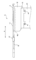
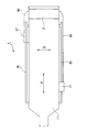
- FIG. 1 is a schematic diagram of an X-ray imaging apparatus as a radiation imaging apparatus according to the present invention. It is a side surface schematic diagram of the examination table. 1 is a schematic plan view of an examination table 1.
- FIG. FIG. 6 is a schematic side view showing a state where the operation unit 17 is mounted on a rail 15.
- FIG. 4 is a perspective view of a storage unit 2.
- FIG. 4 is a perspective view of a storage unit 2.
- FIG. 1 is a schematic diagram of an X-ray imaging apparatus as a radiation imaging apparatus according to the present invention.
- the X-ray imaging apparatus detects an X-ray irradiation unit 31 including an X-ray tube and a collimator, and X-rays that have been irradiated from the X-ray irradiation unit 31 and passed through a subject lying on the examination table 1.
- a flat panel detector 32 as an X-ray detection unit, a substantially C-shaped C-type arm 33 that supports the X-ray irradiation unit 31 and the flat panel detector 32, and a slide that supports the C-type arm 33 so as to be slidable.
- An arcuate guide portion 37 is formed on the C-shaped arm 33, and the slide portion 34 supports the C-shaped arm 33 in a slidable state by engaging with the guide portion 37.
- the C-shaped arm 33 forms an X-ray irradiation unit 31 and a flat panel detector 32, and an X-ray axis extending from the focal point of the X-ray tube in the X-ray irradiation unit 31 to the flat panel detector 32 forms a guide unit 37. It is supported in a state where it matches the diameter of the arc.
- the swivel unit 35 swivels the slide unit 34 around the axis orthogonal to the X-ray axis extending from the focal point of the X-ray tube to the flat panel detector 32 together with the C-shaped arm 33 and the like.
- X-ray fluoroscopy or X-ray imaging is performed on the subject on the examination table 1 from any direction by sliding and turning the C-shaped arm 33. It becomes possible.
- FIG. 2 is a schematic side view of the examination table 1.
- FIG. 3 is a schematic plan view of the examination table 1.
- the examination table 1 includes a top board 11 on which a subject is placed, a first support part 12, a second support part 13, and a third support part 14.
- the top plate 11 is reciprocated in the longitudinal direction indicated by the arrow A in FIGS. 2 and 3 with respect to the first support portion 12, the second support portion 13, and the third support portion 14 by being guided by the guide member 42. Moving.
- This longitudinal direction is the body axis direction of the subject lying on the top plate 11.
- the examinee uses the side of the top plate 11 where the width is reduced (left side in FIGS. 2 and 3) as the head side, and the opposite side (right side in FIGS. 2 and 3) as the foot side. 11 lying down.
- the 2nd support part 13 is guided to the guide member 41, and with respect to the 3rd support part 14 with the top plate 11 and the 1st support part 12 in the transversal direction shown by arrow B in FIG. Move back and forth.
- This short direction is a direction orthogonal to the above-described longitudinal direction.
- the first support portion 12 swings around the axis parallel to the longitudinal direction with respect to the second support portion 13 together with the top plate 11 by a swing mechanism (not shown).
- a pair of rails 15 are disposed on both sides of the top plate 11 in the short direction (both sides with respect to the body axis of the subject placed on the top plate 11).
- the operation unit 17 is detachably attached to these rails 15 at arbitrary positions. That is, the operation unit 17 is attached to the top plate 11 via the rail 15.
- the operation unit 17 is for changing the posture of the C-arm 33, moving the top 11 of the examination table 1, or performing various X-ray imaging operations.
- the cable 16 is connected to the operation unit 17.
- An end region of the cable 16 opposite to the operation unit 17 is stored in the storage unit 2 of the cable 16.
- the cable 16 has a length that allows the operation unit 17 to be attached to the rail 15 at any position. That is, the cable 16 has a length that allows the operation unit 17 to be attached to all attachment regions where the operation unit 17 is attached to the top plate 11 via the rail 15.
- the storage part 2 of the cable 16 is in a state of being connected to an end region of the top plate 11 on the foot side (right side in FIGS. 2 and 3) of the subject placed on the top plate 11. It is arranged.
- FIG. 4 is a schematic side view showing a state in which the operation unit 17 is mounted on the rail 15.
- the operation unit 17 includes an operation area 18 for executing various operations. Various operation buttons, a touch panel type display unit, and the like are disposed in the operation area 18. The operation unit 17 is also provided with an operation lever or the like as necessary. The operation portion 17 is disposed so as to be swingable about the shaft 28 with respect to the support portion 19. The support portion 19 is attached to the rail 15 described above using the operation screw 29.
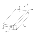
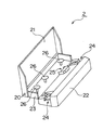
- FIG. 5 and 6 are perspective views of the storage unit 2 described above. 5 shows a state in which the lid 21 in the storage unit 2 is closed, and FIG. 6 shows a state in which the lid 21 in the storage unit 2 is opened.
- the storage unit 2 includes a box composed of a block-shaped member 22 and a dish-shaped member 23, and a lid 21 that covers the top of the box.
- the lid body 21 is disposed so as to be swingable around the shaft 20 with respect to the dish-like member 23 in the box constituted by the block-like member 22 and the dish-like member 23.
- FIG. 5 when the lid 21 is closed, the upper portion of the dish-like member 23 in the box composed of the block-like member 22 and the dish-like member 23 is covered with the lid 21.
- the upper surface of the lid 21 and the surface of the top plate 11 in the storage unit 2 are arranged at the same height and are in the same plane.
- the operation unit 17 On the side surfaces (the side surfaces on both sides in the short direction indicated by the arrow B in FIG. 3) on both sides of the body axis of the subject placed on the top plate 11 in the block-shaped member 22 constituting the box, the operation unit 17.
- a hole 24 for allowing the cable 16 connected to the cable to pass therethrough is formed. As shown in FIG. 5, the hole 24 is open toward the outside even when the lid 21 is in a closed state covering the box.
- a hole 25 for guiding the cable 16 to the first support portion 12 is formed in the block-shaped member 22 constituting the box.
- three winding members 26 around which the cable 16 can be wound are disposed on the dish-like member 23 constituting the box.
- the examination table 1 corresponding to the arrangement relationship between the C-shaped arm 33 and the examination table 1, the standing position of the operator who operates the operation unit 17, and the like.
- An operation unit 17 is attached to a predetermined position in the pair of rails 15 disposed on the top plate 11.
- the extra length portion of the cable 16 extending from the operation unit 17 is stored in a box made up of the block-shaped member 22 and the dish-shaped member 23 in the storage unit 2 with the lid 21 in the storage unit 2 opened.
- the cable 16 enters the box through any one of the holes 24 formed on both side surfaces of the block-shaped member 22 constituting the box.
- the lid body 21 is closed.
- the lid 21 in the storage unit 2 When the lid 21 in the storage unit 2 is in a closed state, as shown in FIG. 2, the upper surface of the lid 21 and the surface of the top plate 11 in the storage unit 2 are arranged at the same height position. Coplanar. For this reason, it is possible to place a device or the like used during X-ray imaging on the upper portion of the lid 21.
- the imaging direction from the X-ray irradiation unit 31 to the flat panel detector 32 is changed with respect to the examination table 1, thereby changing the attachment position of the operation unit 17 with respect to the top plate 11.
- the present invention is applied to the examination table 1 used in the X-ray imaging apparatus using other imaging methods. May be.
Landscapes
- Health & Medical Sciences (AREA)
- Life Sciences & Earth Sciences (AREA)
- Engineering & Computer Science (AREA)
- Medical Informatics (AREA)
- Radiology & Medical Imaging (AREA)
- Molecular Biology (AREA)
- Biophysics (AREA)
- Nuclear Medicine, Radiotherapy & Molecular Imaging (AREA)
- Optics & Photonics (AREA)
- Pathology (AREA)
- Physics & Mathematics (AREA)
- Biomedical Technology (AREA)
- Heart & Thoracic Surgery (AREA)
- High Energy & Nuclear Physics (AREA)
- Surgery (AREA)
- Animal Behavior & Ethology (AREA)
- General Health & Medical Sciences (AREA)
- Public Health (AREA)
- Veterinary Medicine (AREA)
- Human Computer Interaction (AREA)
- Apparatus For Radiation Diagnosis (AREA)
Abstract
天板に載置される被検者の足側に配設された収納部2は、ブロック状部材22と皿状部材23とから構成される箱体と、この箱体の上部を覆う蓋体21と、を備える。蓋体21は、ブロック状部材22と皿状部材23とから構成される箱体における皿状部材23に対して、軸20を中心に揺動可能に配設されている。蓋体21が閉止状態となったときには、ブロック状部材22と皿状部材23とから構成される箱体における皿状部材23の上部がこの蓋体21により覆われる。この状態においては、図2に示すように、収納部2における蓋体21の上面と天板の表面とは、同じ高さ位置に配置され、同一平面状となる。
Description
この発明は、検診台上の被検者に対して放射線透視または放射線撮影を行う放射線撮影装置に関する。
例えば、循環器系の検査および手術を行う場合に使用されるX線撮影装置は、被検者を載置する天板を備えた検診台と、X線管と、X線管から照射され検診台上の被検者を通過したX線を検出するX線検出部と、円弧状の案内部を有しX線管とX線検出部とを支持する略C字状のC型アームと、円弧状の案内部と係合することによりC型アームをスライド可能に支持するスライド機構と、スライド機構を介してC型アームを水平方向を向く軸心を中心に回動可能に支持する回動機構と、を備えている。また、被検者を異なる二方向から撮影するバイプレーン方式のX線撮影装置は、上述したX線管とX線検出部とを有するC型アームを一対配設した構成を有する。
このようなX線撮影装置は、C型アームおよび検診台における天板の移動操作や、各種のX線撮影操作等を実行させるための操作部を備えている。この操作部は、C型アームと検診台との配置関係や、この操作部を操作する操作者の立ち位置等に対応して、検診台における天板に対して互いに異なる複数の方向から装着可能となっている。特許文献1においては、操作部を、検診台に対して3方向から装着可能としたX線撮影装置が開示されている。
各種の操作を行うための操作部は、ケーブルを介して検診台と接続されている。一方、検診台における天板は、X線撮影の態様により、支持部に対して水平移動および昇降する構成となっている。このため、天板に配設された操作部から延びるケーブルは、天板の移動を考慮して、余裕のある長さとなっている。
また、上述したように、操作部は、C型アームと検診台との配置関係や、この操作部を操作する操作者の立ち位置等に対応して、検診台における天板に対して互いに異なる複数の方向から装着可能となっている。また、被検者が天板上に乗り、また、天板から降りるときには、操作部を天板から一旦取り外すこともある。このような理由からも、操作部から延びるケーブルは、余裕のある長さとなっている。
このように、検診台の天板に装着された操作部から延びるケーブルの長さが余裕長を考慮したものとされ、ケーブルにたるみが発生した場合においては、被検者等がケーブルに引っ掛かり、ケーブルに断線が生じる可能性がある。また、ケーブルのたるみは、清潔性の観点からも問題となる。
この発明は上記課題を解決するためになされたものであり、操作部を天板に対して互いに異なる複数の方向から装着する場合においても、ケーブルのたるみを解消することが可能な放射線撮影装置を提供することを目的とする。
請求項1に記載の発明は、検診台と、前記検診台上の被検者に対して放射線を照射する放射線照射部と、前記放射線照射部から照射され前記被検者を透過した放射線を検出する放射線検出部と、を備えた放射線撮影装置において、前記検診台は、前記被検者を載置する天板と、前記天板を支持部に対して移動させる天板移動機構と、前記天板に対して互いに異なる複数の方向から装着可能な操作部と、前記天板における前記天板に載置される被検者の足側に配設され、前記操作部に接続されたケーブルを収納可能な箱体と、前記箱体の上部を覆う蓋体と、を備えることを特徴とする。
請求項2に記載の発明は、請求項1に記載の発明において、前記箱体における前記天板に載置される被検者の体軸に対する両側の側面に、前記ケーブルを通過させるための孔部が形成される。
請求項3に記載の発明は、請求項2に記載の発明において、前記箱体の内部に、前記ケーブルを巻回可能な巻回部材が配設される。
請求項4に記載の発明は、請求項3に記載の発明において、前記天板の両側にレールが配設され、前記操作部は、前記レールを介して前記天板に装着される。
請求項5に記載の発明は、請求項3に記載の発明において、円弧状の案内部を有し前記放射線照射部と前記放射線検出部とを支持するC型アームと、前記円弧状の案内部と係合することにより前記C型アームをスライド可能に支持するスライド機構と、前記スライド機構を介して前記C型アームを回動可能に支持する回動機構と、をさらに備える。
請求項1に記載の発明によれば、操作部を天板に対して互いに異なる複数の方向から装着する場合においても、ケーブルの余長部分を箱体内に収納することにより、ケーブルのたるみを解消することが可能となる。
請求項2に記載の発明によれば、操作部が天板の両側の側面のいずれに装着された場合においても、ケーブルを、孔部を介して箱体内に案内することが可能となる。
請求項3に記載の発明によれば、ケーブルにおける余長部分を巻回部材に巻回することにより、ケーブルを箱体内に整理された状態で収納することが可能となる。
請求項4に記載の発明によれば、天板の両側のレールのいずれの領域に操作部が配置された場合においても、ケーブルのたるみを解消することが可能となる。
請求項5に記載の発明によれば、C型アームの姿勢の変更に伴って操作部を天板に対して各種の位置に配置する場合においても、ケーブルのたるみを解消することが可能となる。
以下、この発明の実施の形態を図面に基づいて説明する。図1は、この発明に係る放射線撮影装置としてのX線撮影装置の概要図である。
このX線撮影装置は、X線管とコリメータとから成るX線照射部31と、このX線照射部31から照射されて検診台1上に横たわった被検者を通過したX線を検出するX線検出部としてのフラットパネルディテクタ32と、これらのX線照射部31およびフラットパネルディテクタ32を支持する略C字状のC型アーム33と、このC型アーム33をスライド可能に支持するスライド部34と、このスライド部34を旋回させる旋回部35と、この旋回部35を床面に対して立設した状態で支持する支持部36とを備える。
C型アーム33には、円弧状の案内部37が形成されており、スライド部34は、この案内部37に係合することにより、C型アーム33をスライド可能な状態で支持している。そして、C型アーム33は、X線照射部31とフラットパネルディテクタ32とを、X線照射部31におけるX線管の焦点からフラットパネルディテクタ32に至るX線の軸線が、案内部37を形成する円弧の直径と一致する状態で支持している。また、旋回部35は、スライド部34をC型アーム33等とともに、X線管の焦点からフラットパネルディテクタ32に至るX線の軸線と直交する軸を中心に旋回させる。このような構成を有するX線撮影装置においては、C型アーム33をスライドおよび旋回させることにより、検診台1上の被検者に対して任意の方向からX線透視またはX線撮影を実行することが可能となる。
次に、この発明の特徴部分である検診台1の構成について説明する。図2は、検診台1の側面概要図である。また、図3は、検診台1の平面概要図である。
この検診台1は、被検者を載置する天板11と、第1支持部12と、第2支持部13と、第3支持部14とを備える。天板11は、ガイド部材42に案内されることにより、第1支持部12、第2支持部13、第3支持部14に対して、図2および図3において矢印Aで示す長手方向に往復移動する。この長手方向は、天板11上に横たわる被検者の体軸方向である。なお、被検者は、天板11の幅が小さくなった側(図2および図3における左側)を頭部側とし、その逆側(図2および図3における右側)を足側として天板11上に横たわる。
また、第2支持部13は、ガイド部材41に案内されることにより、天板11および第1支持部12とともに、第3支持部14に対して、図3において矢印Bで示す短手方向に往復移動する。この短手方向は、上述した長手方向と直交する方向である。また、第1支持部12は、図示しない揺動機構により、天板11とともに、第2支持部13に対して、長手方向と平行な軸を中心として揺動する。
天板11における短手方向の両側(天板11に載置される被検者の体軸に対する両側)には、一対のレール15が配設されている。そして、操作部17が、これらレール15に対して、任意の位置に着脱可能に装着されている。すなわち、操作部17は、レール15を介して天板11に装着されている。この操作部17は、C型アーム33の姿勢を変更し、また検診台1における天板11を移動させ、あるいは、各種のX線撮影操作等を実行させるためのものである。
この操作部17には、ケーブル16が接続されている。このケーブル16における操作部17とは逆側の端部領域は、ケーブル16の収納部2の内部に収納されている。このケーブル16は、操作部17を、レール15に対してどの位置にも装着可能な長さを有する。すなわち、このケーブル16は、天板11に対してレール15を介して操作部17を装着する全ての装着領域に対して操作部17を装着可能な長さを有する。なお、ケーブル16の収納部2は、天板11における、この天板11に載置される被検者の足側(図2および図3における右側)の端部領域に連設される状態で配設されている。
図4は、操作部17をレール15に装着した状態を示す側面概要図である。
この操作部17は、各種の操作を実行するための操作領域18を備える。この操作領域18には、各種の操作ボタンやタッチパネル式の表示部等が配設される。また、この操作部17には、必要に応じ、操作レバー等も配設される。この操作部17は、支持部19に対して、軸28を中心に揺動可能に配設されている。支持部19は、操作ネジ29を利用して、上述したレール15に装着される。
図5および図6は、上述した収納部2の斜視図である。なお、図5は、収納部2における蓋体21を閉止した状態を示し、図6は、収納部2における蓋体21を開放した状態を示している。
この収納部2は、ブロック状部材22と皿状部材23とから構成される箱体と、この箱体の上部を覆う蓋体21と、を備える。蓋体21は、ブロック状部材22と皿状部材23とから構成される箱体における皿状部材23に対して、軸20を中心に揺動可能に配設されている。図5に示すように、蓋体21が閉止状態となったときには、ブロック状部材22と皿状部材23とから構成される箱体における皿状部材23の上部がこの蓋体21により覆われる。この状態においては、図2に示すように、収納部2における蓋体21の上面と天板11の表面とは、同じ高さ位置に配置され、同一平面状となる。
箱体を構成するブロック状部材22における天板11に載置される被検者の体軸に対する両側の側面(図3において矢印Bで示す短手方向の両側の側面)には、操作部17に接続されたケーブル16を通過させるための孔部24が形成されている。この孔部24は、図5に示すように、蓋体21が箱体を覆う閉止状態となったときにも、外部に向けて開口した状態となっている。
図6に示すように、箱体を構成するブロック状部材22には、ケーブル16を第1支持部12に案内するための孔部25が形成されている。また、箱体を構成する皿状部材23には、ケーブル16を巻回可能な3個の巻回部材26が配設されている。
以上のような構成を有するX線撮影装置においては、C型アーム33と検診台1との配置関係や、この操作部17を操作する操作者の立ち位置等に対応して、検診台1における天板11に配設された一対のレール15における所定の位置に操作部17が取り付けられる。そして、収納部2における蓋体21を開放した状態で、操作部17から延びるケーブル16の余長部分を、収納部2におけるブロック状部材22と皿状部材23とから構成される箱体内に収納する。このときには、ケーブル16は、箱体を構成するブロック状部材22における両側の側面に形成されたいずれかの孔部24を介して箱体内に侵入する。そして、必要に応じ、ケーブル16の余長部分が、3個の巻回部材26のうちの複数の巻回部材26に巻回された後、蓋体21が閉止される。
この状態においては、ケーブル16の余長部分は、収納部2における箱体内に収納されていることから、ケーブル16にたるみが発生することを防止することが可能となる。このため、被検者等がケーブル16に引っ掛かり、ケーブル16に断線が生じたり、ケーブル16のたるみによりケーブル16が汚染されたりすることはない。なお、このケーブル16は、箱体を構成するブロック状部材22に形成された孔部25を介して、図2に示す第1支持部12に到達している。このため、天板11が図2および図3に矢印Aで示す長手方向や矢印Bで示す短手方向に移動する構成としたときにも、ケーブル16が外部で垂れ下がる等の現象を生ずることはない。
また、収納部2における蓋体21が閉止状態となったときには、図2に示すように、収納部2における蓋体21の上面と天板11の表面とは、同じ高さ位置に配置され、同一平面状となる。このため、蓋体21の上部に、X線撮影時に使用される機器等を載置することが可能となる。
なお、上述した実施形態においては、操作部17を天板11の両側に配設した一対のレール15に装着する場合について説明したが、例えば、収納部2におけるブロック状部材22にさらにレールを配設し、操作部17を天板11に対して3方向から装着する構成を採用してもよい。
また、上述した実施形態においては、検診台1に対してX線照射部31からフラットパネルディテクタ32に至る撮影方向が変化し、それにより操作部17の天板11に対する取り付け位置を変更することが特に要請されるC型アーム33を有するX線撮影装置にこの発明を適用した場合について説明したが、その他の撮影方式によるX線撮影装置に使用される検診台1に対してこの発明を適用してもよい。
1 検診台
2 収納部
11 天板
12 第1支持部
13 第2支持部
14 第3支持部
15 レール
16 ケーブル
17 操作部
18 操舵領域
19 支持部
20 軸
21 蓋体
22 ブロック状部材
23 皿状部材
24 孔部
25 孔部
26 巻回部材
31 X線発生部
32 フラットパネルディテクタ
33 C型アーム
34 スライド部
35 旋回部
36 支持部
41 ガイド部材
42 ガイド部材
2 収納部
11 天板
12 第1支持部
13 第2支持部
14 第3支持部
15 レール
16 ケーブル
17 操作部
18 操舵領域
19 支持部
20 軸
21 蓋体
22 ブロック状部材
23 皿状部材
24 孔部
25 孔部
26 巻回部材
31 X線発生部
32 フラットパネルディテクタ
33 C型アーム
34 スライド部
35 旋回部
36 支持部
41 ガイド部材
42 ガイド部材
Claims (5)
- 検診台と、前記検診台上の被検者に対して放射線を照射する放射線照射部と、前記放射線照射部から照射され前記被検者を透過した放射線を検出する放射線検出部と、を備えた放射線撮影装置において、
前記検診台は、
前記被検者を載置する天板と、
前記天板を支持部に対して移動させる天板移動機構と、
前記天板に対して互いに異なる複数の方向から装着可能な操作部と、
前記天板における前記天板に載置される被検者の足側に配設され、前記操作部に接続されたケーブルを収納可能な箱体と、
前記箱体の上部を覆う蓋体と、
を備えることを特徴とする放射線撮影装置。 - 請求項1に記載の放射線撮影装置において、
前記箱体における前記天板に載置される被検者の体軸に対する両側の側面に、前記ケーブルを通過させるための孔部が形成される放射線撮影装置。 - 請求項2に記載の放射線撮影装置において、
前記箱体の内部に、前記ケーブルを巻回可能な巻回部材が配設される放射線撮影装置。 - 請求項3に記載の放射線撮影装置において、
前記天板の両側にレールが配設され、
前記操作部は、前記レールを介して前記天板に装着される放射線撮影装置。 - 請求項3に記載の放射線撮影装置において、
円弧状の案内部を有し前記放射線照射部と前記放射線検出部とを支持するC型アームと、
前記円弧状の案内部と係合することにより前記C型アームをスライド可能に支持するスライド機構と、
前記スライド機構を介して前記C型アームを回動可能に支持する回動機構と、
をさらに備える放射線撮影装置。
Priority Applications (3)
| Application Number | Priority Date | Filing Date | Title |
|---|---|---|---|
| PCT/JP2017/013890 WO2018185802A1 (ja) | 2017-04-03 | 2017-04-03 | 放射線撮影装置 |
| JP2019510502A JP6708301B2 (ja) | 2017-04-03 | 2017-04-03 | 放射線撮影装置 |
| US16/495,986 US10881361B2 (en) | 2017-04-03 | 2017-04-03 | Radiographic imaging apparatus |
Applications Claiming Priority (1)
| Application Number | Priority Date | Filing Date | Title |
|---|---|---|---|
| PCT/JP2017/013890 WO2018185802A1 (ja) | 2017-04-03 | 2017-04-03 | 放射線撮影装置 |
Publications (1)
| Publication Number | Publication Date |
|---|---|
| WO2018185802A1 true WO2018185802A1 (ja) | 2018-10-11 |
Family
ID=63713016
Family Applications (1)
| Application Number | Title | Priority Date | Filing Date |
|---|---|---|---|
| PCT/JP2017/013890 Ceased WO2018185802A1 (ja) | 2017-04-03 | 2017-04-03 | 放射線撮影装置 |
Country Status (3)
| Country | Link |
|---|---|
| US (1) | US10881361B2 (ja) |
| JP (1) | JP6708301B2 (ja) |
| WO (1) | WO2018185802A1 (ja) |
Families Citing this family (3)
| Publication number | Priority date | Publication date | Assignee | Title |
|---|---|---|---|---|
| WO2018185802A1 (ja) * | 2017-04-03 | 2018-10-11 | 株式会社島津製作所 | 放射線撮影装置 |
| WO2021165331A1 (en) * | 2020-02-19 | 2021-08-26 | Koninklijke Philips N.V. | Temporarily attachment of medical equipment to a subject support |
| KR102598188B1 (ko) * | 2021-04-15 | 2023-11-02 | (주)씨비에이치 | 의료용 테이블 |
Citations (2)
| Publication number | Priority date | Publication date | Assignee | Title |
|---|---|---|---|---|
| JP2006525839A (ja) * | 2003-05-09 | 2006-11-16 | コーニンクレッカ フィリップス エレクトロニクス エヌ ヴィ | 配線誘導手段を備える患者支持テーブル |
| JP2010274058A (ja) * | 2009-06-01 | 2010-12-09 | Canon Inc | 放射線撮影システム |
Family Cites Families (14)
| Publication number | Priority date | Publication date | Assignee | Title |
|---|---|---|---|---|
| DE3464322D1 (en) * | 1984-05-04 | 1987-07-30 | Siemens Ag | Patient's support |
| NL8900638A (nl) * | 1989-03-16 | 1990-10-16 | Philips Nv | Roentgenonderzoek apparaat. |
| JP3367685B2 (ja) * | 1992-05-20 | 2003-01-14 | 株式会社東芝 | ケーブル処理装置およびその装置を備えた磁気共鳴イメージング装置 |
| DE60004014T2 (de) * | 1999-12-08 | 2004-04-22 | Koninklijke Philips Electronics N.V. | Träger für medizinische zwecke mit einem grossen verstellungsbereich |
| JP4988995B2 (ja) * | 2001-06-29 | 2012-08-01 | キヤノン株式会社 | X線撮影用テーブル及びx線撮影装置 |
| JP2004105606A (ja) * | 2002-09-20 | 2004-04-08 | Toshiba Corp | X線診断装置 |
| JP2004173907A (ja) * | 2002-11-27 | 2004-06-24 | Canon Inc | X線撮像装置 |
| US20070055145A1 (en) * | 2005-08-23 | 2007-03-08 | Zelnik Deborah R | Methods and apparatus for nuclear tomo-cardiology scanning |
| WO2007047457A2 (en) * | 2005-10-13 | 2007-04-26 | Volcano Corporation | Component-based catheter lab intravascular ultrasound system |
| EP2081490B1 (en) * | 2006-10-31 | 2015-05-13 | Koninklijke Philips N.V. | Patient bed for pet/mr imaging systems |
| DE102013215406B4 (de) * | 2013-08-06 | 2023-03-16 | Siemens Healthcare Gmbh | Verfahren und Vorrichtung zur Visualisierung eines Funktionsablaufs einer medizinischen Apparatur |
| JP6183239B2 (ja) | 2014-02-12 | 2017-08-23 | 株式会社島津製作所 | X線透視撮影装置 |
| EP4241750A3 (en) * | 2014-12-05 | 2023-12-20 | Egg Medical, Inc. | A multimodality medical procedure mattress-based device |
| WO2018185802A1 (ja) * | 2017-04-03 | 2018-10-11 | 株式会社島津製作所 | 放射線撮影装置 |
-
2017
- 2017-04-03 WO PCT/JP2017/013890 patent/WO2018185802A1/ja not_active Ceased
- 2017-04-03 JP JP2019510502A patent/JP6708301B2/ja active Active
- 2017-04-03 US US16/495,986 patent/US10881361B2/en active Active
Patent Citations (2)
| Publication number | Priority date | Publication date | Assignee | Title |
|---|---|---|---|---|
| JP2006525839A (ja) * | 2003-05-09 | 2006-11-16 | コーニンクレッカ フィリップス エレクトロニクス エヌ ヴィ | 配線誘導手段を備える患者支持テーブル |
| JP2010274058A (ja) * | 2009-06-01 | 2010-12-09 | Canon Inc | 放射線撮影システム |
Also Published As
| Publication number | Publication date |
|---|---|
| JPWO2018185802A1 (ja) | 2020-01-23 |
| US10881361B2 (en) | 2021-01-05 |
| JP6708301B2 (ja) | 2020-06-10 |
| US20200046304A1 (en) | 2020-02-13 |
Similar Documents
| Publication | Publication Date | Title |
|---|---|---|
| JP2001190535A (ja) | 血管撮影・ct装置 | |
| EP3342349B1 (en) | Robotic operating table and hybrid operating system | |
| US20150117603A1 (en) | Detector assembly for recording x-ray images of an object to be imaged | |
| JP6708301B2 (ja) | 放射線撮影装置 | |
| WO2013125146A1 (ja) | 患者傾動装置付きカウチ | |
| JP2019213583A (ja) | 近接操作式x線透視撮影装置 | |
| ITUB20156291A1 (it) | Dispositivo d'imaging radiologico | |
| KR20120103143A (ko) | 듀얼 실링 엑스레이 시스템 | |
| KR20150052669A (ko) | 방사선 진단 장치 | |
| WO2012161210A1 (ja) | X線診断装置 | |
| JP5504705B2 (ja) | X線撮影装置 | |
| JP5099055B2 (ja) | 放射線断層撮影装置 | |
| JP6613884B2 (ja) | 放射線透視装置 | |
| JP2012005731A (ja) | X線診断装置 | |
| RU2587313C1 (ru) | Универсальный рентгеновский комплекс | |
| JP5091506B2 (ja) | X線診断装置 | |
| JP4466338B2 (ja) | Cアーム形x線透視撮影装置 | |
| JP2021074261A (ja) | 放射線撮影装置 | |
| JP2016086818A (ja) | 検診台 | |
| JP6607089B2 (ja) | 放射線撮影装置 | |
| JPWO2018186477A1 (ja) | 放射線撮影装置 | |
| JP5630407B2 (ja) | X線診断装置 | |
| JP2020081410A (ja) | X線撮影装置 | |
| JP5910455B2 (ja) | X線撮影装置のコリメータ機構およびx線撮影装置 | |
| JP6708768B2 (ja) | ロボット手術台およびハイブリッド手術室 |
Legal Events
| Date | Code | Title | Description |
|---|---|---|---|
| 121 | Ep: the epo has been informed by wipo that ep was designated in this application |
Ref document number: 17904763 Country of ref document: EP Kind code of ref document: A1 |
|
| ENP | Entry into the national phase |
Ref document number: 2019510502 Country of ref document: JP Kind code of ref document: A |
|
| NENP | Non-entry into the national phase |
Ref country code: DE |
|
| 122 | Ep: pct application non-entry in european phase |
Ref document number: 17904763 Country of ref document: EP Kind code of ref document: A1 |