WO2018181787A1 - 車両の制動制御装置 - Google Patents
車両の制動制御装置 Download PDFInfo
- Publication number
- WO2018181787A1 WO2018181787A1 PCT/JP2018/013389 JP2018013389W WO2018181787A1 WO 2018181787 A1 WO2018181787 A1 WO 2018181787A1 JP 2018013389 W JP2018013389 W JP 2018013389W WO 2018181787 A1 WO2018181787 A1 WO 2018181787A1
- Authority
- WO
- WIPO (PCT)
- Prior art keywords
- value
- discharge amount
- target value
- pump
- hydraulic pressure
- Prior art date
- Legal status (The legal status is an assumption and is not a legal conclusion. Google has not performed a legal analysis and makes no representation as to the accuracy of the status listed.)
- Ceased
Links
Images



Classifications
-
- B—PERFORMING OPERATIONS; TRANSPORTING
- B60—VEHICLES IN GENERAL
- B60T—VEHICLE BRAKE CONTROL SYSTEMS OR PARTS THEREOF; BRAKE CONTROL SYSTEMS OR PARTS THEREOF, IN GENERAL; ARRANGEMENT OF BRAKING ELEMENTS ON VEHICLES IN GENERAL; PORTABLE DEVICES FOR PREVENTING UNWANTED MOVEMENT OF VEHICLES; VEHICLE MODIFICATIONS TO FACILITATE COOLING OF BRAKES
- B60T13/00—Transmitting braking action from initiating means to ultimate brake actuator with power assistance or drive; Brake systems incorporating such transmitting means, e.g. air-pressure brake systems
- B60T13/10—Transmitting braking action from initiating means to ultimate brake actuator with power assistance or drive; Brake systems incorporating such transmitting means, e.g. air-pressure brake systems with fluid assistance, drive, or release
- B60T13/12—Transmitting braking action from initiating means to ultimate brake actuator with power assistance or drive; Brake systems incorporating such transmitting means, e.g. air-pressure brake systems with fluid assistance, drive, or release the fluid being liquid
- B60T13/16—Transmitting braking action from initiating means to ultimate brake actuator with power assistance or drive; Brake systems incorporating such transmitting means, e.g. air-pressure brake systems with fluid assistance, drive, or release the fluid being liquid using pumps directly, i.e. without interposition of accumulators or reservoirs
- B60T13/20—Transmitting braking action from initiating means to ultimate brake actuator with power assistance or drive; Brake systems incorporating such transmitting means, e.g. air-pressure brake systems with fluid assistance, drive, or release the fluid being liquid using pumps directly, i.e. without interposition of accumulators or reservoirs with control of pump driving means
-
- B—PERFORMING OPERATIONS; TRANSPORTING
- B60—VEHICLES IN GENERAL
- B60T—VEHICLE BRAKE CONTROL SYSTEMS OR PARTS THEREOF; BRAKE CONTROL SYSTEMS OR PARTS THEREOF, IN GENERAL; ARRANGEMENT OF BRAKING ELEMENTS ON VEHICLES IN GENERAL; PORTABLE DEVICES FOR PREVENTING UNWANTED MOVEMENT OF VEHICLES; VEHICLE MODIFICATIONS TO FACILITATE COOLING OF BRAKES
- B60T8/00—Arrangements for adjusting wheel-braking force to meet varying vehicular or ground-surface conditions, e.g. limiting or varying distribution of braking force
-
- H—ELECTRICITY
- H02—GENERATION; CONVERSION OR DISTRIBUTION OF ELECTRIC POWER
- H02P—CONTROL OR REGULATION OF ELECTRIC MOTORS, ELECTRIC GENERATORS OR DYNAMO-ELECTRIC CONVERTERS; CONTROLLING TRANSFORMERS, REACTORS OR CHOKE COILS
- H02P29/00—Arrangements for regulating or controlling electric motors, appropriate for both AC and DC motors
Definitions
- the present invention relates to a vehicle braking control device applied to a braking device including an electric pump that supplies brake fluid into a wheel cylinder.
- a differential pressure adjusting valve disposed in a fluid path connecting a wheel cylinder and a master cylinder, a pump for supplying brake fluid to the wheel cylinder side with respect to the differential pressure regulating valve in the fluid path, and a pump
- a device including an electric motor that is a power source of the motor.
- the differential pressure between the master cylinder and the wheel cylinder, that is, the liquid in the wheel cylinder is controlled by controlling at least one of the opening instruction value for the differential pressure adjusting valve and the discharge amount of the brake fluid of the pump. The pressure can be adjusted.
- Patent Document 1 describes an example of a braking control device that increases the discharge amount of brake fluid of a pump when a hydraulic pressure target value that is a hydraulic pressure target value in a wheel cylinder is increased.
- the braking control device described in Patent Document 1 when the hydraulic pressure target value is increased, the target value of the electric motor rotation speed is increased as the hydraulic pressure target value is increased. A target value for the rotational speed is calculated. Then, the driving of the electric motor is controlled based on the target value of the rotational speed calculated in this way.
- the amount of brake fluid supplied to the wheel cylinder increases due to an increase in the amount of brake fluid discharged from the pump, so that the fluid pressure in the wheel cylinder can be increased to follow the increase in the fluid pressure target value.
- a vehicle braking control device for solving the above-described problem is provided in a vehicle braking device including a pump that supplies brake fluid to a wheel cylinder provided for a wheel, and an electric motor that is a power source of the pump.
- Applicable equipment includes a hydraulic pressure control unit that controls the hydraulic pressure in the wheel cylinder by driving the electric motor based on an instruction value for the rotation speed of the electric motor every predetermined control cycle, and a wheel. Calculate the motor speed target value for each control cycle so that the motor speed target value, which is the target value of the electric motor rotation speed, increases as the amount of increase in the hydraulic pressure target value, which is the target value of the hydraulic pressure in the cylinder, increases.
- the motor target calculation unit that controls the calculation value that is a value corresponding to the difference between the target value of one of the rotation speed of the electric motor and the hydraulic pressure in the wheel cylinder, minus the actual value of the one value And a difference calculation unit derived for each cycle.
- the hydraulic pressure control unit instructs the previous value of the actual rotation speed of the electric motor.
- the instruction value is derived so that the instruction value increases as the upper limit of the value and the motor speed target value increases, and the instruction value increases as the operation value derived by the difference calculation unit increases.
- the “actual value” here is a concept including not only a value detected by a detection system such as a sensor but also a value estimated and calculated based on a control mode such as an electric motor.
- a control mode such as an electric motor.
- the target value of the rotational speed of the electric motor is increased. Further, the greater the difference obtained by subtracting the actual rotational speed of the electric motor from the motor speed target value, or the greater the difference obtained by subtracting the actual value of the hydraulic pressure in the wheel cylinder from the hydraulic pressure target value, The calculated value increases.
- the motor speed target value is less than the previous value of the actual rotational speed of the electric motor
- the indicated value is set to be larger than the motor speed target value within a range not exceeding the previous value of the actual speed of the electric motor. can do. Therefore, compared with the case where the command value is held at the motor speed target value, the time required to increase the hydraulic pressure in the wheel cylinder to the hydraulic pressure target value increases as the pump brake fluid discharge amount increases. Hateful.
- the vehicle occupant When the operating sound of the electric motor is constant, the vehicle occupant does not feel so uncomfortable with the operating sound of the electric motor. However, when the magnitude of the operating sound of the electric motor suddenly increases, the vehicle occupant tends to feel uncomfortable with the operating noise as compared with the case where the magnitude of the operating noise is constant.
- the motor speed target value is less than the previous value of the actual value of the rotational speed of the electric motor
- the instruction value does not exceed the previous value of the actual value of the rotational speed of the electric motor. Therefore, it is possible to suppress a sudden increase in the rotational speed of the electric motor, and as a result, it is possible to suppress a sudden increase in the operating noise of the electric motor.
- a motor speed instruction value that is an instruction value for the rotation speed of the electric motor is derived for each predetermined control cycle, and is based on the motor speed instruction value.
- the hydraulic pressure control unit that controls the hydraulic pressure in the wheel cylinder, and the increase in the hydraulic target value, which is the target value of the hydraulic pressure in the wheel cylinder, increases the brake fluid of the pump.
- a pump target calculation unit that calculates a pump discharge target value for each control cycle so that a pump discharge target value that is a target value of the discharge amount is large, a pump brake fluid discharge amount, and a hydraulic pressure in the wheel cylinder
- a difference calculation unit that derives a calculation value that is a value corresponding to a difference obtained by subtracting the actual value of the one value from the target value of any one of the values, and a pump target calculation unit.
- a pump instruction value deriving unit for deriving a pump discharge amount instruction value that is an instruction value for the pump brake fluid discharge amount based on the pump discharge amount target value and the operation value derived by the difference operation unit; ing.
- the hydraulic pressure control unit derives the motor speed instruction value so that the motor speed instruction value increases as the pump discharge amount instruction value derived by the pump instruction value deriving unit increases. Further, the pump instruction value deriving unit determines the actual amount of brake fluid discharged from the pump when the pump discharge amount target value calculated by the pump target calculating unit is less than the previous value of the actual value of pump brake fluid discharge. The previous value of the value is set as the upper limit of the pump discharge amount instruction value, and the pump discharge amount instruction value increases as the pump discharge amount target value increases, and the pump discharge amount instruction increases as the calculation value derived by the difference calculation unit increases. The pump discharge amount instruction value is derived so as to increase the value.
- the pump discharge amount target value when the hydraulic pressure target value is increased, the pump discharge amount target value is increased. Further, the larger the difference between the pump discharge target value and the pump brake fluid actual value, the greater the difference, or the greater the difference between the hydraulic pressure target value and the actual hydraulic pressure in the wheel cylinder.
- the calculated value increases as the value increases.
- the pump discharge amount target value is less than the previous value of the pump brake fluid discharge amount
- the pump discharge amount instruction value is within a range not exceeding the previous value of the pump brake fluid discharge amount. Can be made larger than the pump discharge amount target value.
- the pump discharge amount instruction value derived in this way is converted into a motor speed instruction value, and the drive of the electric motor is controlled based on the motor speed instruction value. Therefore, compared with the case where the pump discharge amount instruction value is held at the pump discharge amount target value, it is necessary to increase the hydraulic pressure in the wheel cylinder to the hydraulic pressure target value as the pump brake fluid discharge amount increases. Time is hard to be long.
- the pump discharge amount instruction value is the previous value of the actual value of the pump brake fluid discharge amount.
- the pump discharge amount target value is less than the previous value of the actual value of the brake fluid discharge of the pump
- the pump discharge amount instruction value is the previous value of the actual value of the pump brake fluid discharge amount.
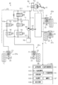
- FIG. 1 illustrates a vehicle including a control device 100 that is a braking control device of the present embodiment.
- the vehicle includes a plurality of braking mechanisms 20a, 20b, 20c, and 20d that are individually provided for the respective wheels FL, FR, RL, and RR (that is, the same number as the wheels), and a braking device 40.
- Each of the braking mechanisms 20a to 20d includes a wheel cylinder 21 to which brake fluid is supplied, a disk rotor 22 that rotates integrally with the wheels FL, FR, RL, and RR, and friction that relatively moves in a direction toward and away from the disk rotor 22.
- Each has a material 23.
- the WC pressure Pwc which is the hydraulic pressure in the wheel cylinder 21
- the force that presses the friction material 23 against the disk rotor 22, that is, the braking force against the wheels FL, FR, RL, and RR Each can be enlarged.
- the braking device 40 includes a hydraulic pressure generating device 50 to which a braking operation member 41 such as a brake pedal operated by a driver is coupled, and a braking actuator capable of individually adjusting the WC pressure Pwc in each wheel cylinder 21. 60.
- a braking operation member 41 such as a brake pedal operated by a driver
- a braking actuator capable of individually adjusting the WC pressure Pwc in each wheel cylinder 21. 60.
- braking operation the operation of the braking operation member 41 by the driver
- the force by which the driver operates the braking operation member 41 is also referred to as “braking operation force”.
- the hydraulic pressure generator 50 includes a master cylinder 51, a booster 52 that assists the braking operation force input to the braking operation member 41, and a reservoir tank 53 that stores the brake fluid.
- a master cylinder 51 when a braking operation force assisted by the booster 52 is input, an MC pressure Pmc that is a hydraulic pressure corresponding to the braking operation force is generated.
- the brake actuator 60 is provided with two systems of hydraulic circuits 611 and 612.
- a wheel cylinder 21 corresponding to the left front wheel FL and a wheel cylinder 21 corresponding to the right rear wheel RR are connected to the first hydraulic circuit 611.
- the second hydraulic circuit 612 is connected to a wheel cylinder 21 corresponding to the right front wheel FR and a wheel cylinder 21 corresponding to the left rear wheel RL.
- a differential pressure adjusting valve 62 for adjusting the differential pressure between the master cylinder 51 and the wheel cylinder 21 is provided in the fluid path connecting the master cylinder 51 and the wheel cylinder 21. Further, in the first hydraulic circuit 611, a fluid path 63a for the left front wheel and a fluid path 63d for the right rear wheel are provided on the wheel cylinder 21 side of the differential pressure regulating valve 62.
- the liquid passages 63a and 63d are provided with a holding valve 64 that is closed when the increase in the WC pressure Pwc is restricted, and a pressure reducing valve 65 that is opened when the WC pressure Pwc is decreased.
- the differential pressure regulating valve 62 is a normally open linear solenoid valve
- the holding valve 64 is a normally open solenoid valve
- the pressure reducing valve 65 is a normally closed solenoid valve.
- the first hydraulic circuit 611 is connected to a reservoir 66 that temporarily stores brake fluid that has flowed out of the wheel cylinder 21 via the pressure reducing valve 65, and a pump 68 that operates based on driving of the electric motor 67.
- the electric motor 67 is a “power source of the pump 68”.
- the reservoir 66 is connected to the pump 68 via the suction flow path 69 and is connected to the liquid path closer to the master cylinder 51 than the differential pressure regulating valve 62 via the master side flow path 70.
- the pump 68 is connected to a connection portion 72 between the differential pressure regulating valve 62 and the holding valve 64 via a supply flow channel 71. Therefore, when the electric motor 67 is driven, the pump 68 draws the brake fluid in the master cylinder 51 through the reservoir 66 and discharges the brake fluid to the connection portion 72.
- the structure of the second hydraulic circuit 612 is substantially the same as the structure of the first hydraulic circuit 611; therefore, the description of the structure of the second hydraulic circuit 612 is omitted in this specification.
- the control device 100 includes a hydraulic pressure estimation unit 101, a hydraulic pressure target calculation unit 102, and a motor as functional units for driving the electric motor 67, that is, for controlling the brake fluid discharge amount of the pump 68.
- a speed calculation unit 103, an upper limit setting unit 104, a motor target calculation unit 105, a difference calculation unit 106, an integration unit 107, and a hydraulic pressure control unit 108 are provided.
- the hydraulic pressure estimation unit 101 estimates and calculates the WC pressure Pwc in each wheel cylinder 21.
- the hydraulic pressure estimation unit 101 includes the MC pressure Pmc in the master cylinder 51, the rotational speed VMt of the electric motor 67 that is the rotational speed of the output shaft of the electric motor 67, and the opening instruction value for the differential pressure adjustment valve 62. And so on.
- the WC pressure Pwc increases as the MC pressure Pmc increases, increases as the rotational speed VMt of the electric motor 67 increases, and increases as the opening instruction value for the differential pressure regulating valve 62 decreases.
- the hydraulic pressure estimation unit 101 also calculates a control hydraulic pressure PwcC that is a differential pressure between the master cylinder 51 side from the differential pressure adjustment valve 62 and the wheel cylinder 21 side from the differential pressure adjustment valve 62.
- the hydraulic pressure estimation unit 101 can set the difference obtained by subtracting the MC pressure Pmc from the estimated WC pressure Pwc as the control hydraulic pressure PwcC.
- the hydraulic pressure target calculation unit 102 calculates a control hydraulic pressure target value PwcCTr that is a target value of the control hydraulic pressure PwcC.
- the control hydraulic pressure target value PwcCTr is an example of “a target value for the WC pressure Pwc in the wheel cylinder 21”.
- the hydraulic pressure target calculation unit 102 can calculate the control hydraulic pressure target value PwcCTr so that the control hydraulic pressure target value PwcCTr increases as the braking force target value for the vehicle increases.
- the motor speed calculation unit 103 calculates the rotational speed VMt of the electric motor 67.
- the motor speed calculation unit 103 can calculate the rotation speed VMt based on a signal output from a resolver provided in the electric motor 67. That is, in the present embodiment, the rotation speed VMt calculated by the motor speed calculation unit 103 corresponds to an example of “actual value of rotation speed”.
- the upper limit setting unit 104 calculates a motor speed upper limit value VMtL, which is an upper limit value of the rotational speed VMt of the electric motor 67, according to the type of braking control being performed. Specifically, when a highly urgent braking control such as an emergency automatic braking or an antilock brake control for the purpose of avoiding a collision with an obstacle is performed, the upper limit setting unit 104 determines the motor speed. The upper limit value VMtL is made relatively large. On the other hand, when the braking control with a low degree of urgency is being performed, the upper limit setting unit 104 sets the motor speed upper limit value VMtL to a smaller value than when the braking control with a high degree of urgency is being performed. In addition, as braking control with low urgency, for example, automatic braking in adaptive cruise control and driving torque transmitted to the outer driving wheel during turning by applying braking force to the inner driving wheel during turning For example, torque vectoring control to be increased.
- braking control with low urgency for example, automatic braking in adaptive cruise control and driving
- the motor target calculation unit 105 is based on the control hydraulic pressure target value PwcCTr calculated by the hydraulic pressure target calculation unit 102 and the motor speed upper limit value VMtL set by the upper limit setting unit 104, and the rotational speed VMt of the electric motor 67.
- the motor speed target value VMtTr which is the target value of is calculated.
- the difference calculation unit 106 derives a calculation value ⁇ VMt that is a difference obtained by subtracting the rotation speed VMt of the electric motor 67 calculated by the motor speed calculation unit 103 from the motor speed target value VMtTr calculated by the motor target calculation unit 105.
- the accumulating unit 107 derives a correction value X that is a value obtained by accumulating the calculated value ⁇ VMt calculated by the difference calculating unit 106.
- the hydraulic pressure control unit 108 derives an instruction value VMtI with respect to the rotational speed VMt of the electric motor 67 and drives the electric motor 67 based on the instruction value VMtI, so that the WC pressure Pwc in the wheel cylinder 21, that is, the control fluid.
- the pressure PwcC is controlled.
- the larger the instruction value VMtI the higher the rotational speed VMt of the electric motor 67, and the greater the amount of brake fluid discharged from the pump 68.
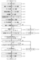
- This processing routine is executed every predetermined control cycle while the braking control is being performed.
- the count number N which is the number of executions of the present processing routine from the start of the braking control, is incremented by “1”. This count number N is reset to “0” when the execution of the braking control is finished and this processing routine is not executed.
- the rotation speed VMt (N) of the electric motor 67 is calculated by the motor speed calculation unit 103.
- the control hydraulic pressure target value PwcCTr (N) calculated by the hydraulic pressure target calculation unit 102 is acquired.
- the control hydraulic pressure target value PwcCTr is calculated for each control cycle that is the same as this processing routine.
- the motor target calculation unit 105 converts the control hydraulic pressure target value PwcCTr (N) into the required fluid amount FV (N).
- the required fluid amount FV (N) is the amount of brake fluid to be supplied from the pump 68 to the wheel cylinder 21 in order to make the control fluid pressure PwcC equal to the control fluid pressure target value PwcCTr. Therefore, the required fluid amount FV (N) increases as the control fluid pressure target value PwcCTr increases.
- step S15 the motor target calculation unit 105 calculates the change amount ⁇ FV of the necessary liquid amount FV. That is, when the required liquid amount FV derived when the processing routine is executed last time is set to the previous value FV (N ⁇ 1) of the required liquid amount, the motor target calculation unit 105 calculates the necessary liquid amount derived in step S14. A difference obtained by subtracting the previous value FV (N ⁇ 1) of the necessary liquid amount from the amount FV (N) is defined as a change amount ⁇ FV.
- the motor target calculation unit 105 calculates a pump discharge amount target value SpTr, which is a discharge amount per unit time of the pump 68.
- the target value SpTr of the pump discharge amount is obtained by adding the amount of brake fluid flowing to the differential pressure adjusting valve 62 side of the brake fluid discharged from the pump 68 to the required fluid amount change amount ⁇ FV calculated in step S15. Can be derived.
- the relief amount which is the amount of brake fluid flowing to the differential pressure adjustment valve 62 side, is smaller as the opening instruction value for the differential pressure adjustment valve 62 is smaller, that is, as the electromagnetic force generated in the differential pressure adjustment valve 62 is larger. Less.
- the motor speed upper limit value VMtL set by the upper limit setting unit 104 is acquired.
- the motor speed calculation unit 103 calculates the motor speed target value VMtTr (N). That is, the motor speed calculation unit 103 sets the product of the pump discharge amount target value SpTr calculated in step S16 and the conversion coefficient M as the motor speed target value candidate value VMtTrF.
- the conversion coefficient M is a coefficient for converting the brake fluid discharge amount of the pump 68 into the rotation speed of the electric motor 67.
- the motor speed calculation unit 103 derives a motor speed target value VMtTr (N) based on the motor speed target value candidate value VMtTrF and the motor speed upper limit value VMtL.
- the motor speed calculation unit 103 sets the smaller one of the motor speed target value candidate value VMtTrF and the motor speed upper limit value VMtL as the motor speed target value VMtTr (N).
- the motor speed target value candidate value VMtTrF is a value corresponding to the necessary fluid amount change amount ⁇ FV corresponding to the change amount of the control fluid pressure target value PwcCTr as described above. Therefore, when the motor speed target value candidate value VMtTrF is less than or equal to the motor speed upper limit value VMtL, the motor speed calculation unit 103 increases the amount of change in the required fluid amount ⁇ FV, that is, increases the control fluid pressure target value PwcCTr.
- the motor speed target value VMtTr (N) can be calculated so that the motor speed target value VMtTr (N) increases as the number increases.
- step S19 it is determined whether or not driving of the electric motor 67 is requested. If driving is requested (step S19: YES), the process proceeds to the next step S20.
- the calculated value ⁇ VMt (N) which is the difference obtained by subtracting the previous value VMt (N ⁇ 1) of the rotational speed of the electric motor 67 from the previous value VMtTr (N ⁇ 1) of the motor speed target value, is calculated as a difference. Derived by the unit 106.
- the previous value VMtTr (N ⁇ 1) of the motor speed target value is the motor speed target value VMtTr derived when this processing routine was executed last time.
- the previous value VMt (N ⁇ 1) of the rotation speed of the electric motor 67 is the rotation speed VMt calculated when this processing routine was executed last time.
- the summing unit 107 adds the calculated value ⁇ VMt (N) to the previous value X (N ⁇ 1) of the correction value to be the correction value X (N). That is, in step S21, the calculation value ⁇ VMt is integrated. And a process transfers to step S24 mentioned later.
- step S22 the calculated value ⁇ VMt (N) is made equal to “0”.
- step S23 the correction value X (N) is made equal to “0”. Thereafter, the process proceeds to the next step S24.
- step S24 the hydraulic pressure control unit 108 calculates a correction value VMtTrA for the motor speed target value. That is, the hydraulic pressure control unit 108 sets the correction value VMtTrA of the motor speed target value, the motor speed target value VMtTr (N) derived in step S18, and the correction value X (N) derived in step S21 or step S23. And the sum of Subsequently, in step S25, whether or not the motor speed target value VMtTr (N) calculated in step S18 by the hydraulic pressure control unit 108 is less than the previous value VMt (N-1) of the rotational speed of the electric motor 67. Is determined.
- step S25: NO When the motor speed target value VMtTr (N) is equal to or higher than the previous rotation speed value VMt (N-1) (step S25: NO), the process proceeds to step S28 described later. On the other hand, when the motor speed target value VMtTr (N) is less than the previous rotation speed value VMt (N-1) (step S25: YES), the process proceeds to the next step S26.
- step S26 the hydraulic pressure control unit 108 determines whether or not the control hydraulic pressure target value PwcCTr (N) acquired in step S13 is greater than or equal to the previous value PwcCTr (N-1) of the control hydraulic pressure target value.
- the The previous value PwcCTr (N ⁇ 1) of the control hydraulic pressure target value is the control hydraulic pressure target value PwcCTr acquired at the previous execution of this processing routine. Therefore, when the control hydraulic pressure target value PwcCTr (N) is equal to or greater than the previous value PwcCTr (N ⁇ 1) of the control hydraulic pressure target value, it cannot be determined that the control hydraulic pressure target value PwcCTr is decreasing. On the other hand, when the control hydraulic pressure target value PwcCTr (N) is less than the previous value PwcCTr (N ⁇ 1) of the control hydraulic pressure target value, it can be determined that the control hydraulic pressure target value PwcCTr is decreasing.
- step S27 the hydraulic pressure control unit 108 derives an instruction value VMtI for the rotational speed VMt of the electric motor 67. Specifically, the hydraulic pressure control unit 108 is the smaller of the correction value VMtTrA of the motor speed target value derived in step S24 and the previous value VMt (N ⁇ 1) of the rotation speed of the electric motor 67. The value is designated as an instruction value VMtI. Thereafter, the process proceeds to step S29 described later.
- control hydraulic pressure target value PwcCTr (N) is less than the previous value PwcCTr (N-1) of the control hydraulic pressure target value in step S26 (NO), the process proceeds to the next step S28.
- step S28 the hydraulic pressure control unit 108 makes the instruction value VMtI for the rotation speed of the electric motor 67 equal to the motor speed target value VMtTr (N) calculated in step S18. Thereafter, the process proceeds to the next step S29.
- step S29 the hydraulic pressure control unit 108 controls the driving of the electric motor 67 based on the instruction value VMtI derived in step S27 or step S28. Thereafter, this processing routine is once terminated.
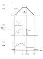
- the candidate value VMtTrF exceeds the motor speed upper limit value VMtL.
- the motor speed target value VMtTr becomes equal to the motor speed upper limit value VMtL.
- the instruction value VMtI is held at the motor speed target value VMtTr. Then, the drive of the electric motor 67 is controlled based on such an instruction value VMtI.
- the rotation speed VMt of the electric motor 67 increases toward the motor speed target value VMtTr.
- the rotational speed VMt is lower than the motor speed target value VMtTr, and thus the calculated value ⁇ VMt is larger than “0”. Therefore, the correction value X, which is an integrated value of the calculated value ⁇ VMt, gradually increases.
- the motor speed target value VMtTr (N) is less than the previous value VMt (N ⁇ 1) of the rotation speed of the electric motor 67.
- the control hydraulic pressure target value PwcCTr is not decreased. Therefore, the correction value VMtTrA of the motor speed target value, which is the sum of the correction value X (N) added to the motor speed target value VMtTr (N), and the previous value VMt (N ⁇ 1) of the rotation speed of the electric motor 67. The smaller one of them is derived as the instruction value VMtI.
- the previous value VMt (N ⁇ 1) of the rotation speed is set as the upper limit of the instruction value, and the instruction value VMtI increases as the motor speed target value VMtTr (N) increases, and the calculated value ⁇ VMt (N) increases.
- the instruction value VMtI is derived so that the instruction value VMtI increases.
- the correction value VMtTrA of the motor speed target value is the previous value of the rotation speed of the electric motor 67. VMt (N-1) or more.
- the instruction value VMtI is made equal to the previous value VMt (N ⁇ 1) of the rotation speed.
- the correction value X gradually decreases as shown in FIG.
- the correction value VMtTrA of the motor speed target value is less than the previous value VMt (N ⁇ 1) of the rotational speed, so the instruction value VMtI is the motor speed target. It becomes equal to the value correction value VMtTrA. That is, the instruction value VMtI gradually decreases.
- the WC pressure Pwc in the wheel cylinder 21 reaches the control hydraulic pressure target value PwcCTr, and the correction value X becomes equal to “0”. Therefore, the instruction value VMtI is held at “0” after the fifth timing t15. As a result, the drive of the electric motor 67 is stopped and the brake fluid is not supplied from the pump 68.
- the rotation speed target value VMtTr (N) when the motor speed target value VMtTr (N) is less than the previous value VMt (N-1) of the rotation speed of the electric motor 67, the rotation speed is not in excess of the previous value VMt (N-1).
- the instruction value VMtI can be made larger than the motor speed target value VMtTr (N).
- the WC pressure Pwc in the wheel cylinder 21 is set to the control hydraulic pressure target by the amount that the brake fluid discharge amount of the pump 68 is corrected to be increased as compared with the case where the instruction value VMtI is made equal to the motor speed target value VMtTr (N).
- the time required to increase the value PwcCTr is unlikely to be long.
- the instruction value VMtI is compared with the case where the previous value VMt (N ⁇ 1) of the rotational speed is not set as the upper limit. Can be suppressed. As a result, an abrupt change in the magnitude of the operating sound of the electric motor 67 can be suppressed.
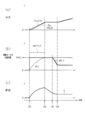
- the opening instruction value of the differential pressure regulating valve 62 is held at a constant value from the start of the braking control to the start of the decrease in the WC pressure Pwc, but the WC pressure Pwc It is assumed that the opening degree instruction value is gradually increased when decreasing.
- the control hydraulic pressure target value PwcCTr is increased.
- the operation of the pump 68 that is, the drive of the electric motor 67 is started, and the opening degree instruction value of the differential pressure adjusting valve 62 is adjusted.
- the control fluid pressure target value PwcCTr is increased, so the change amount ⁇ FV of the required fluid amount is “0”. Bigger than.
- the calculated motor speed target value candidate value VMtTrF exceeds the motor speed upper limit value VMtL.
- the motor speed target value VMtTr is equal to the motor speed upper limit value VMtL.
- the correction value VMtTrA of the motor speed target value is the previous value VMt ( N-1) or more.
- the instruction value VMtI is equal to the previous value VMt (N ⁇ 1) of the rotation speed.
- the rotational speed VMt of the electric motor 67 is higher than the motor speed target value VMtTr, and thus the calculated value ⁇ VMt becomes a negative value.
- the correction value X gradually decreases as shown in FIG.
- the control hydraulic pressure target value PwcCTr is gradually decreased toward “0”. As described above, when the control hydraulic pressure target value PwcCTr is decreased, the WC pressure Pwc in the wheel cylinder 21 is decreased. If the instruction value VMtI is made larger than the motor speed target value VMtTr when the WC pressure Pwc is reduced in this way, it becomes difficult to reduce the WC pressure Pwc as the brake fluid discharge amount of the pump 68 increases.
- the motor speed target value VMtTr is the rotation of the electric motor 67. Even if the speed is less than the previous value VMt (N ⁇ 1), the instruction value VMtI is not equal to the motor speed target value correction value VMtTrA, but is equal to the motor speed target value VMtTr. As a result, it is possible to suppress the decrease in the WC pressure Pwc in the wheel cylinder 21 as much as the amount of brake fluid discharged from the pump 68 can be suppressed.
- the instruction value VMtI is not made larger than the motor speed target value VMtTr, so that an increase in power consumption of the electric motor 67 can be suppressed. .
- the rotational speed VMt of the electric motor 67 becomes equal to “0” at the fourth timing t24, and the rotational speed VMt is held at “0” after the fourth timing t24. Therefore, although the correction value X decreases in conjunction with the decrease in the rotational speed VMt during the period from the third timing t23 to the fourth timing t24, it is held after the fourth timing t24. Then, at the fifth timing t25, the control hydraulic pressure target value PwcCTr becomes equal to “0”, and it is determined that driving of the electric motor 67 is unnecessary. As a result, the correction value X is reset to “0”.
- the control hydraulic pressure target value PwcCTr is increased.
- the operation of the pump 68 that is, the drive of the electric motor 67 is started, and the opening degree instruction value of the differential pressure adjusting valve 62 is adjusted.
- the control fluid pressure target value PwcCTr is increased in the period from the first timing t31 to the second timing t32, and therefore the required fluid amount change amount ⁇ FV is less than “0”. Is also big.
- the calculated motor speed target value candidate value VMtTrF exceeds the motor speed upper limit value VMtL.
- the motor speed target value VMtTr is equal to the motor speed upper limit value VMtL.
- the motor speed target value VMtTr (N) is less than the previous value VMt (N-1) of the rotational speed of the electric motor 67, and the control hydraulic pressure target The value PwcCTr is not decreased.
- the motor speed target value correction value VMtTrA which is the sum of the motor speed target value VMtTr (N) and the correction value X (N)
- the instruction value VMtI is equal to the previous value VMt (N ⁇ 1) of the rotation speed.
- the correction value VMtTrA of the motor speed target value is equal to or less than the previous value VMt (N ⁇ 1) of the rotation speed of the electric motor 67. It becomes. Therefore, in the period, the instruction value VMtI is equal to the motor speed target value correction value VMtTrA.
- the correction value VMtTrA of the motor speed target value gradually decreases during the period, and thus the instruction value VMtI also gradually decreases.
- the control hydraulic pressure target value PwcCTr is increased again. Then, the change amount ⁇ FV of the necessary liquid amount becomes larger than “0”, and thus the motor speed target value candidate value VMtTrF becomes larger than “0”. In the example shown in FIG. 5, the candidate value VMtTrF does not exceed the motor speed upper limit value VMtL.
- the motor speed target value VMtTr (N) becomes equal to or greater than the previous value VMt (N-1) of the rotation speed of the electric motor 67. Therefore, the instruction value VMtI is made equal to the motor speed target value VMtTr (N).
- the instruction value VMtI can be set to a value larger than the previous value VMt (N ⁇ 1) of the rotational speed, the increase in the brake fluid discharge amount of the pump 68 is not limited, and the wheel cylinder 21
- the WC pressure Pwc can be increased early. Therefore, it is possible to suppress an increase in the difference between the WC pressure Pwc in the wheel cylinder 21 and the control hydraulic pressure target value PwcCTr.
- the above embodiment may be changed to another embodiment as described below.
- the previous value VMtTr (N) is less than the previous value VMt (N ⁇ 1) of the rotation speed of the electric motor 67
- the previous value VMt The instruction value VMtI may be made larger than the motor speed target value VMtTr (N) within a range not exceeding (N-1).
- the smaller value of the previous value VMt (N ⁇ 1) of the rotation speed and the correction value VMtTrA of the motor speed target value may be set as the instruction value VMtI.
- the power consumption in the electric motor 67 is slightly increased as compared with the above-described embodiment
- the WC pressure Pwc in the wheel cylinder 21 is decreased by increasing the opening instruction value of the differential pressure adjusting valve 62. Can be delayed.
- the difference calculation unit 106 may derive a difference obtained by subtracting the WC pressure Pwc in the wheel cylinder 21 from the control hydraulic pressure target value PwcCTr as a hydraulic pressure difference calculation value.
- the WC pressure Pwc used for calculating the hydraulic pressure difference calculation value corresponds to an example of “actual value of WC pressure”.
- the difference calculation unit 106 may derive the difference obtained by subtracting the value obtained by converting the WC pressure Pwc into the liquid amount from the value obtained by converting the control hydraulic pressure target value PwcCTr into the liquid amount as the liquid amount difference calculation value. .
- the difference calculation unit 106 derives the calculation value ⁇ VMt (N) by performing conversion processing for converting the hydraulic pressure difference calculation value or the liquid amount difference calculation value into the rotation speed of the electric motor 67. .
- the calculation value ⁇ VMt (N) is calculated, it is possible to obtain the same effect as that of the above embodiment.
- a second embodiment of the vehicle braking control apparatus Next, a second embodiment of the vehicle braking control apparatus will be described with reference to FIGS.
- a method for setting a motor speed instruction value VMtI that is an instruction value for the rotation speed VMt of the electric motor 67 is different from that of the first embodiment. Therefore, in the following description, parts different from those of the first embodiment will be mainly described, and the same or corresponding member configurations as those of the first embodiment are denoted by the same reference numerals, and redundant description will be given. Shall be omitted.
- FIG. 6 shows a control device 100A of the present embodiment and a braking actuator 60 whose operation is controlled by the control device 100A.
- the braking actuator 60 includes a pump 68, an electric motor 67 that is a power source of the pump 68, and a differential pressure adjustment valve 62.
- the control device 100 ⁇ / b> A includes a hydraulic pressure estimation unit 111, a hydraulic pressure target calculation unit 112, and a motor as functional units for driving the electric motor 67, that is, for controlling the brake fluid discharge amount of the pump 68.
- a speed calculation unit 113, a pump discharge amount calculation unit 114, a pump target calculation unit 115, a difference calculation unit 116, an integration unit 117, an upper limit setting unit 118, a pump instruction value deriving unit 119, and a hydraulic pressure control unit 120 are provided.
- the hydraulic pressure estimation unit 111 estimates and calculates the WC pressure Pwc in each wheel cylinder 21 in the same manner as the hydraulic pressure estimation unit 101 in the first embodiment. In addition, the hydraulic pressure estimation unit 111 calculates the control hydraulic pressure PwcC as in the hydraulic pressure estimation unit 101 in the first embodiment.
- the hydraulic pressure target calculation unit 112 calculates the control hydraulic pressure target value PwcCTr in the same manner as the hydraulic pressure target calculation unit 102 in the first embodiment.
- This control hydraulic pressure target value PwcCTr is an example of a “hydraulic pressure target value” that is a target value for the WC pressure Pwc in the wheel cylinder 21.
- the motor speed calculation unit 113 calculates the rotation speed VMt of the electric motor 67 in the same manner as the motor speed calculation unit 103 in the first embodiment.
- the pump discharge amount calculation unit 114 calculates a pump discharge amount Sp that is a brake fluid discharge amount per unit time of the pump 68 based on the rotation speed VMt of the electric motor 67 calculated by the motor speed calculation unit 113.
- the pump discharge amount calculation unit 114 calculates the pump discharge amount Sp so that the pump discharge amount Sp increases as the rotational speed VMt increases.
- the pump discharge amount Sp calculated by the pump discharge amount calculation unit 114 corresponds to an example of “actual value of pump discharge amount”.
- the sensor which can detect a pump discharge amount is provided in the braking actuator 60, you may make it use the detected value detected based on the signal from a sensor as the pump discharge amount Sp.
- the pump target calculation unit 115 calculates a pump discharge amount target value SpTr that is a target value of the pump discharge amount Sp that is a discharge amount of brake fluid per unit time of the pump 68. That is, as the amount of increase in the control hydraulic pressure PwcC calculated by the hydraulic pressure estimation unit 111 increases, it is necessary to cause more brake fluid to flow into the wheel cylinder 21. Therefore, the pump target calculation unit 115 calculates the pump discharge amount target value SpTr so that the pump discharge amount target value SpTr increases as the increase amount of the control hydraulic pressure PwcC increases.
- the difference calculation unit 116 derives a calculation value ⁇ Sp that is a difference obtained by subtracting the pump discharge amount Sp calculated by the pump discharge amount calculation unit 114 from the pump discharge amount target value SpTr calculated by the pump target calculation unit 115.
- the accumulating unit 117 derives a correction value Z that is a value obtained by accumulating the calculated value ⁇ Sp calculated by the difference calculating unit 116.
- the upper limit setting unit 118 calculates a pump discharge amount upper limit SpL, which is an upper limit value of the pump discharge amount Sp, according to the type of braking control being performed. Specifically, when braking control with a high degree of urgency is being performed as described above, the upper limit setting unit 118 relatively increases the pump discharge amount upper limit SpL. On the other hand, when the braking control with a low degree of urgency is being performed as described above, the upper limit setting unit 118 sets the pump discharge amount upper limit SpL to a smaller value than when the braking control with a high degree of urgency is being performed. To do.
- the pump instruction value deriving unit 119 calculates the pump discharge amount target value SpTr calculated by the pump target calculating unit 115 and the calculated value ⁇ Sp derived by the difference calculating unit 116 (specifically, the correction derived by the integrating unit 117). Based on the value Z), a pump discharge amount instruction value SpI which is an instruction value for the pump discharge amount Sp is derived.
- the hydraulic pressure control unit 120 derives a motor speed instruction value VMtI that is an instruction value for the rotational speed VMt of the electric motor 67 based on the pump discharge amount instruction value SpI derived by the pump instruction value deriving unit 119.
- the hydraulic pressure control unit 120 controls the WC pressure Pwc in the wheel cylinder 21, that is, the control hydraulic pressure PwcC, by driving the electric motor 67 based on the derived motor speed instruction value VMtI.
- This processing routine is executed every predetermined control cycle while the braking control is being performed.
- the count number N is incremented by “1”. This count number N is reset to “0” when the execution of the braking control is finished and this processing routine is not executed.
- the rotational speed VMt (N) of the electric motor 67 is calculated by the motor speed calculator 113.
- the pump discharge amount Sp (N) is calculated by the pump discharge amount calculation unit 114 based on the rotation speed VMt (N) calculated in step S112.
- the control hydraulic pressure target value PwcCTr (N) calculated by the hydraulic pressure target calculation unit 112 is acquired. The control hydraulic pressure target value PwcCTr is calculated for each control cycle that is the same as this processing routine.
- step S115 the pump target calculation unit 115 converts the control fluid pressure target value PwcCTr (N) into the required fluid amount FV (N).
- the required fluid amount FV (N) increases as the control fluid pressure target value PwcCTr increases.
- step S116 the pump target calculation unit 115 calculates the change amount ⁇ FV of the necessary liquid amount FV. That is, the pump target calculation unit 115 sets the difference ⁇ FV as a difference obtained by subtracting the previous value FV (N ⁇ 1) of the necessary liquid amount from the necessary liquid amount FV (N) derived in step S115.
- step S117 the pump target calculation unit 115 acquires the pump discharge amount upper limit SpL set by the upper limit setting unit 118. Then, in the next step S118, the pump target calculation unit 115 calculates the pump discharge amount target value SpTr (N). That is, the pump target calculation unit 115 calculates the candidate value SpTrF of the pump discharge amount target value SpTr by the same method as the calculation method of the pump discharge amount target value SpTr in step S16 in the first embodiment. Then, the pump target calculation unit 115 sets the smaller one of the pump discharge amount target value candidate value SpTrF and the pump discharge amount upper limit value SpL acquired in step S117 as the pump discharge amount target value SpTr (N). To do.
- the pump discharge amount target value candidate value SpTrF is a value corresponding to the required fluid amount change amount ⁇ FV corresponding to the change amount of the control fluid pressure target value PwcCTr as described above. Therefore, when the pump discharge amount target value candidate value SpTrF is equal to or less than the pump discharge amount upper limit value SpL, the pump target calculation unit 115 increases the required fluid amount change amount ⁇ FV, that is, increases the control fluid pressure target value PwcCTr.
- the pump discharge amount target value SpTr (N) can be calculated so that the pump discharge amount target value SpTr (N) increases as the amount increases.
- next step S119 it is determined whether or not driving of the electric motor 67 is requested. If driving is requested (step S119: YES), the process proceeds to the next step S120.
- the calculated value ⁇ Sp (N) which is a difference obtained by subtracting the previous value Sp (N-1) of the pump discharge amount from the previous value SpTr (N-1) of the pump discharge amount target value, is calculated by the difference calculation unit 116. Is derived by The previous value SpTr (N-1) of the pump discharge amount target value is the pump discharge amount target value SpTr derived when this processing routine was executed last time.
- the previous value Sp (N-1) of the pump discharge amount is the pump discharge amount Sp calculated when this processing routine was executed last time.
- step S121 the summation unit 117 sets the correction value Z (N) as a sum obtained by adding the calculated value ⁇ Sp (N) to the previous correction value Z (N ⁇ 1). That is, in step S121, the calculation values ⁇ Sp are integrated. And a process transfers to step S124 mentioned later.
- step S122 the calculated value ⁇ Sp (N) is made equal to “0”.
- step S123 the correction value Z (N) is made equal to “0”. Thereafter, the process proceeds to the next step S124.
- step S124 the pump instruction value deriving unit 119 calculates the correction value SpTrA of the pump discharge target value. That is, the pump instruction value deriving unit 119 sets the pump discharge amount target value correction value SpTrA to the pump discharge amount target value SpTr (N) derived in step S118 and the correction value Z derived in step S121 or step S123. It is made equal to the sum with (N). Subsequently, in step S125, the pump instruction value deriving unit 119 determines whether the pump discharge amount target value SpTr (N) calculated in step S118 is less than the previous value Sp (N-1) of the pump discharge amount. Determined.
- step S125: NO When the pump discharge amount target value SpTr (N) is equal to or greater than the previous value Sp (N-1) of the pump discharge amount (step S125: NO), the process proceeds to step S128 described later. On the other hand, when the pump discharge amount target value SpTr (N) is less than the previous value Sp (N-1) of the pump discharge amount (step S125: YES), the process proceeds to the next step S126.
- step S126 the pump instruction value deriving unit 119 determines whether or not the control hydraulic pressure target value PwcCTr (N) acquired in step S114 is equal to or greater than the previous value PwcCTr (N-1) of the control hydraulic pressure target value. Is done.
- the process proceeds to the next step S127.
- step S127 the pump discharge amount instruction value SpI is derived by the pump instruction value deriving unit 119.
- the pump instruction value deriving unit 119 uses the smaller value of the correction value SpTrA of the pump discharge amount target value derived in step S124 and the previous value Sp (N-1) of the pump discharge amount as the pump discharge amount.
- the quantity instruction value SpI Thereafter, the process proceeds to step S129 described later.
- control hydraulic pressure target value PwcCTr (N) is less than the previous value PwcCTr (N-1) of the control hydraulic pressure target value in step S126 (NO), the process proceeds to the next step S128.
- step S1208 the pump discharge amount instruction value SpI is made equal to the pump discharge amount target value SpTr (N) calculated in step S118 by the pump instruction value deriving unit 119. Thereafter, the process proceeds to the next step S129.
- step S129 the hydraulic pressure control unit 120 derives the motor speed instruction value VMtI.
- the pump discharge amount Sp increases as the rotational speed VMt of the electric motor 67 increases. Therefore, the hydraulic pressure control unit 120 derives the motor speed instruction value VMtI so that the motor speed instruction value VMtI increases as the pump discharge amount instruction value SpI derived in step S127 or step S128 increases.
- the hydraulic pressure control unit 120 controls the driving of the electric motor 67 based on the motor speed instruction value VMtI derived in step S129. Thereafter, this processing routine is once terminated.
- the control hydraulic pressure target value PwcCTr is increased.
- the operation of the pump 68 that is, the drive of the electric motor 67 is started, and the opening degree instruction value of the differential pressure adjusting valve 62 is adjusted.
- the required fluid amount change amount ⁇ FV is larger than “0”. . Therefore, the candidate value SpTrF of the calculated pump discharge amount target value is increased. In the example described here, the candidate value SpTrF exceeds the pump discharge amount upper limit SpL.
- the pump discharge amount target value SpTr becomes equal to the pump discharge amount upper limit value SpL during the period when the control hydraulic pressure target value PwcCTr is increased.
- the pump discharge amount instruction value SpI is held at the pump discharge amount target value SpTr.
- the driving of the electric motor 67 is controlled based on the motor speed instruction value VMtI corresponding to the pump discharge amount instruction value SpI.
- the pump discharge amount Sp increases toward the pump discharge amount target value SpTr.
- the calculated value ⁇ Sp is “0” in the period in which the pump discharge amount Sp is smaller than the pump discharge amount target value SpTr as in the period from the first timing t11 to the second timing t12 shown in FIG. Bigger than. Therefore, the correction value Z, which is an integrated value of the calculated value ⁇ Sp, gradually increases.
- the required fluid amount change amount ⁇ FV becomes equal to “0”, and therefore the pump discharge amount target value.
- the candidate value SpTrF is also equal to “0”.
- the pump discharge amount target value SpTr becomes equal to the candidate value SpTrF.
- the pump discharge amount target value SpTr (N) is less than the previous value Sp (N-1) of the pump discharge amount.
- the control hydraulic pressure target value PwcCTr is not decreased. Therefore, the correction value SpTrA of the pump discharge amount target value, which is the sum of the correction value Z (N) added to the pump discharge amount target value SpTr (N), and the previous value Sp (N ⁇ 1) of the pump discharge amount. The smaller value is derived as the pump discharge amount instruction value SpI.
- the previous value Sp (N-1) of the pump discharge amount is set as the upper limit of the pump discharge amount instruction value, and the pump discharge amount instruction value SpI increases as the pump discharge amount target value SpTr (N) increases.
- the pump discharge amount instruction value SpI is derived so that the pump discharge amount instruction value SpI increases as the value ⁇ Sp (N) increases.
- the drive of the electric motor 67 is controlled based on the motor speed instruction value VMtI corresponding to the pump discharge amount instruction value SpI derived in this way.
- the correction value SpTrA of the pump discharge amount target value is equal to or greater than the previous value Sp (N ⁇ 1) of the pump discharge amount.
- the pump discharge amount instruction value SpI is made equal to the previous value Sp (N ⁇ 1) of the pump discharge amount.
- the pump discharge amount instruction value SpI is made equal to the previous value Sp (N ⁇ 1) of the pump discharge amount, and the electric motor 67 is driven based on the motor speed instruction value VMtI corresponding to the pump discharge amount instruction value SpI. If controlled, the correction value Z gradually decreases.
- the pump discharge amount instruction value SpI is the correction value of the pump discharge amount target value. It is equal to SpTrA. Therefore, when the correction value Z continues to decrease, the pump discharge amount instruction value SpI and the motor speed instruction value VMtI gradually decrease.
- the pump discharge amount target value SpTr (N) when the pump discharge amount target value SpTr (N) is less than the previous value Sp (N-1) of the pump discharge amount, it is within a range not exceeding the previous value Sp (N-1) of the pump discharge amount.
- the pump discharge amount instruction value SpI can be made larger than the pump discharge amount target value SpTr (N). Therefore, the electric motor 67 is driven based on the motor speed instruction value VMtI corresponding to the pump discharge amount instruction value SpI as compared with the case where the pump discharge amount instruction value SpI is made equal to the pump discharge amount target value SpTr (N). Therefore, the amount of time required to increase the WC pressure Pwc in the wheel cylinder 21 to the control hydraulic pressure target value PwcCTr is less likely to increase because the amount of brake fluid discharged from the pump 68 can be increased.
- the opening instruction value of the differential pressure regulating valve 62 is held at a constant value from the start of the braking control to the start of the decrease in the WC pressure Pwc, but the WC pressure Pwc It is assumed that the opening degree instruction value is gradually increased when decreasing.
- the control hydraulic pressure target value PwcCTr is increased.
- the operation of the pump 68 that is, the drive of the electric motor 67 is started, and the opening degree instruction value of the differential pressure adjusting valve 62 is adjusted.
- the change amount ⁇ FV of the required fluid amount is larger than “0” and the calculated pump discharge amount target value candidate The value SpTrF exceeds the pump discharge amount upper limit SpL.
- the pump discharge amount target value SpTr is equal to the pump discharge amount upper limit value SpL. Therefore, the pump discharge amount instruction value SpI is equal to the pump discharge amount upper limit value SpL.
- the driving of the electric motor 67 is controlled based on the motor speed instruction value VMtI corresponding to the pump discharge amount instruction value SpI.
- the required fluid amount change amount ⁇ FV becomes equal to “0”.
- the candidate value SpTrF of the pump discharge amount target value is also equal to “0”.
- the pump discharge amount target value SpTr becomes equal to the candidate value SpTrF.
- the correction value SpTrA of the pump discharge amount target value becomes equal to or greater than the previous value Sp (N ⁇ 1) of the pump discharge amount.
- the pump discharge amount instruction value SpI is equal to the previous value Sp (N ⁇ 1) of the pump discharge amount.
- the calculated value ⁇ Sp is negative because the pump discharge amount Sp is larger than the pump discharge amount target value SpTr in a period in which the control hydraulic pressure target value PwcCTr is held and the correction value Z is large. It becomes the value of. As a result, the correction value Z gradually decreases.
- the WC pressure Pwc in the wheel cylinder 21 is decreased.
- the pump discharge amount instruction value SpI is made larger than the pump discharge amount target value SpTr, and the electric motor 67 is based on the motor speed instruction value VMtI corresponding to the pump discharge amount instruction value SpI. Is driven, it becomes difficult to reduce the WC pressure Pwc as much as the amount of brake fluid discharged from the pump 68 increases.
- the pump discharge amount even if the pump discharge amount target value SpTr is less than the previous value Sp (N ⁇ 1) of the pump discharge amount.
- the instruction value SpI is not equal to the correction value SpTrA of the pump discharge amount target value but is made equal to the pump discharge amount target value SpTr.
- the driving of the electric motor 67 is controlled based on the motor speed instruction value VMtI corresponding to the pump discharge amount instruction value SpI.
- the motor speed instruction value VMtI is increased by the amount that the pump discharge amount instruction value SpI is not made larger than the pump discharge amount target value SpTr. Can be suppressed. Therefore, an increase in power consumption of the electric motor 67 can be suppressed.
- the correction value Z is “0” during the period when the WC pressure Pwc in the wheel cylinder 21 is still decreasing. The value when the pump discharge amount Sp reaches “0” is held. Then, when the control hydraulic pressure target value PwcCTr becomes equal to “0” and it is determined that the drive of the electric motor 67 is unnecessary, the correction value Z is reset to “0”.
- the control hydraulic pressure target value PwcCTr is increased.
- the operation of the pump 68 that is, the drive of the electric motor 67 is started, and the opening degree instruction value of the differential pressure adjusting valve 62 is adjusted.
- the required fluid amount change amount ⁇ FV is larger than “0”.
- the calculated pump discharge amount target value candidate value SpTrF exceeds the pump discharge amount upper limit SpL.
- the pump discharge amount target value SpTr is equal to the pump discharge amount upper limit value SpL
- the pump discharge amount instruction value SpI is equal to the pump discharge amount upper limit value SpL.
- the driving of the electric motor 67 is controlled based on the motor speed instruction value VMtI corresponding to the pump discharge amount instruction value SpI.
- the required fluid amount change amount ⁇ FV is equal to “0”.
- the candidate value SpTrF of the pump discharge amount target value is held at “0”.
- the pump discharge amount target value SpTr is made equal to the candidate value SpTrF.
- the pump discharge amount target value SpTr (N) is less than the previous value Sp (N ⁇ 1) of the pump discharge amount, and the control hydraulic pressure target value PwcCTr Is not reduced.
- the correction value SpTrA of the pump discharge amount target value which is the sum of adding the correction value Z (N) to the pump discharge amount target value SpTr (N)
- the pump discharge amount instruction value SpI becomes equal to the previous value Sp (N ⁇ 1) of the pump discharge amount.
- the driving of the electric motor 67 is controlled based on the motor speed instruction value VMtI corresponding to the pump discharge amount instruction value SpI.
- the correction value SpTrA of the pump discharge amount target value becomes equal to or less than the previous value Sp (N ⁇ 1) of the pump discharge amount. Become. Then, the pump discharge amount instruction value SpI becomes equal to the correction value SpTrA of the pump discharge amount target value. At this time, when the correction value SpTrA of the pump discharge amount target value is gradually decreased, the pump discharge amount instruction value SpI and the motor speed instruction value VMtI are also gradually decreased. As a result, the pump discharge amount Sp is also gradually reduced.
- the pump discharge amount target value SpTr (N) is equal to or more than the previous value Sp (N-1) of the pump discharge amount. Therefore, the pump discharge amount instruction value SpI is set equal to the pump discharge amount target value SpTr.
- the driving of the electric motor 67 is controlled based on the motor speed instruction value VMtI corresponding to the pump discharge amount instruction value SpI. As a result, the pump discharge amount Sp is gradually increased.
- the pump discharge amount target value SpTr (N) when the pump discharge amount target value SpTr (N) is equal to or greater than the previous value Sp (N-1) of the pump discharge amount, the WC pressure Pwc in the wheel cylinder 21 must be increased unless the brake fluid discharge amount of the pump 68 is increased. And the control hydraulic pressure target value PwcCTr may be increased. Therefore, in the present embodiment, when the pump discharge amount target value SpTr (N) is equal to or greater than the previous value Sp (N-1) of the pump discharge amount, the pump discharge amount instruction value SpI is made equal to the motor speed target value VMtTr. . In this case, the pump discharge amount instruction value SpI can be set to a value larger than the previous value Sp (N ⁇ 1) of the pump discharge amount.
- the increase in the brake fluid discharge amount of the pump 68 is not limited, so the WC pressure Pwc in the wheel cylinder 21 is It can be increased early. Therefore, it is possible to suppress an increase in the difference between the WC pressure Pwc in the wheel cylinder 21 and the control hydraulic pressure target value PwcCTr.
- the above embodiment may be changed to another embodiment as described below.
- the pump discharge amount target value SpTr (N) is less than the previous value Sp (N-1) of the pump discharge amount, even if the control hydraulic pressure target value PwcCTr is decreased, the previous value Sp (N of the pump discharge amount
- the pump discharge amount instruction value SpI may be larger than the pump discharge amount target value SpTr (N) within a range not exceeding -1).
- the smaller one of the previous value Sp (N ⁇ 1) of the pump discharge amount and the correction value SpTrA of the pump discharge amount target value may be set as the pump discharge amount instruction value SpI.
- the pump discharge amount instruction value SpI is You may make it make it equal to the smaller value of the sum which added correction value Z (N) to amount target value SpTr, and pump discharge amount upper limit SpL.
- the difference calculation unit 116 may derive a difference obtained by subtracting the WC pressure Pwc in the wheel cylinder 21 from the control hydraulic pressure target value PwcCTr as a hydraulic pressure difference calculation value.
- the WC pressure Pwc used for calculating the hydraulic pressure difference calculation value corresponds to an example of “actual value of WC pressure”.
- the difference calculation unit 116 may derive the difference obtained by subtracting the value obtained by converting the WC pressure Pwc into the liquid amount from the value obtained by converting the control hydraulic pressure target value PwcCTr into the liquid amount as the liquid amount difference calculation value. .
- the difference calculation unit 116 derives the calculated value ⁇ Sp (N) by performing conversion processing for converting the hydraulic pressure difference calculated value or the liquid amount difference calculated value into the pump discharge amount.
- the calculation value ⁇ Sp (N) is calculated, it is possible to obtain the same effect as that of the above embodiment.
- the hydraulic pressure control unit calculates the motor speed target value and the integration unit. It is preferable that the smaller value of the sum of the calculated integrated values and the previous value of the actual rotation speed of the electric motor is used as the indicated value.
- the pump instruction value deriving unit may calculate the hydraulic pressure target even if the pump discharge amount target value calculated by the pump target calculation unit is less than the previous value of the actual brake fluid discharge amount of the pump. It is preferable that the pump discharge amount instruction value is equal to the pump discharge amount target value on condition that the value is decreased.
- the pump instruction value deriving unit calculates the pump discharge amount target value and the integration unit. It is preferable that a smaller value of the sum of the calculated calculated values and the previous value of the actual pump discharge amount is set as the pump discharge amount instruction value.
- An upper limit setting unit that sets a pump discharge amount upper limit value, which is an upper limit value of the pump discharge amount, according to the type of braking control being performed,
- the pump target calculation unit sets the smaller one of the set pump discharge amount upper limit value and the pump discharge amount according to the increase amount of the hydraulic pressure target value as the pump discharge amount target value. It is preferable.
Landscapes
- Engineering & Computer Science (AREA)
- Transportation (AREA)
- Mechanical Engineering (AREA)
- Power Engineering (AREA)
- Regulating Braking Force (AREA)
Abstract
制御装置は、指示値に基づいてポンプの動力源である電動モータを駆動させることで、ホイールシリンダ内のWC圧を制御する液圧制御部と、液圧目標値の増大量に応じてモータ速度目標値を演算するモータ目標演算部と、電動モータの回転速度及びWC圧の何れか一方の値の目標値から一方の値の実値を減じた差である演算値を導出する差演算部とを備える。液圧制御部は、モータ速度目標値が電動モータの回転速度の実値の前回値未満であるときには、当該前回値を指示値の上限とし、且つ、モータ速度目標値が大きいほど指示値が大きくなるとともに、演算値が大きいほど指示値が大きくなるように、当該指示値を導出する。
Description
本発明は、ホイールシリンダ内にブレーキ液を供給する電動式のポンプを備える制動装置に適用される車両の制動制御装置に関する。
車両の制動装置として、ホイールシリンダとマスタシリンダとを繋ぐ液路に配置されている差圧調整弁と、当該液路における差圧調整弁よりもホイールシリンダ側にブレーキ液を供給するポンプと、ポンプの動力源である電動モータとを備えている装置が知られている。このような制動装置では、差圧調整弁に対する開度指示値とポンプのブレーキ液の吐出量との少なくとも一方を制御することで、マスタシリンダとホイールシリンダとの差圧、すなわちホイールシリンダ内の液圧を調整することができる。
特許文献1には、ホイールシリンダ内の液圧の目標値である液圧目標値が増大されたときにポンプのブレーキ液の吐出量を増大させる制動制御装置の一例が記載されている。この特許文献1に記載の制動制御装置では、液圧目標値が増大されたときには、液圧目標値の増大量が多いほど電動モータの回転速度の目標値が大きくなるように、同電動モータの回転速度の目標値が演算される。そして、このように演算された回転速度の目標値を基に電動モータの駆動が制御される。これにより、ポンプのブレーキ液の吐出量の増大によってホイールシリンダへのブレーキ液の供給量が増えるため、液圧目標値の増大に追随するようにホイールシリンダ内の液圧を増大させることができる。
ところで、特許文献1に記載の制動制御装置にあっては、液圧目標値の増大速度が高いほど、電動モータの回転速度の目標値の上昇速度が高くなる。また、一般的に、電動モータの回転速度が高いほど、電動モータの作動音が大きくなる。そのため、電動モータの回転速度が大きく変化すると、電動モータの作動音の大きさが大きく変化してしまうために車両の乗員が不快に感じるおそれがある。
このような電動モータの作動音の変動を抑制する方法として、電動モータの回転速度に対して上限を設け、回転速度の急上昇を抑えることが考えられる。しかしながら、この場合、液圧目標値の増大量が多いために電動モータの回転速度の目標値が上限を上回った場合、電動モータの回転速度を目標値まで上昇させることができない。その結果、電動モータの作動音の大きさの急変動を抑制することは可能であるものの、ホイールシリンダ内の液圧を液圧目標値まで増大させることができなかったり、当該液圧を液圧目標値まで増大させるのに要する時間が長くなってしまったりし、当該液圧の制御性が低下してしまう。
すなわち、ホイールシリンダ内の液圧の制御性の低下を抑制しつつも、電動モータの作動音の変動を抑えて車両の乗員に不快感を与えにくくするという点で改善の余地がある。
上記課題を解決するための車両の制動制御装置は、車輪に対して設けられているホイールシリンダにブレーキ液を供給するポンプと、ポンプの動力源である電動モータと、を備える車両の制動装置に適用される装置である。この制動制御装置の一態様は、所定の制御サイクル毎に電動モータの回転速度に対する指示値に基づいて電動モータを駆動させることで、ホイールシリンダ内の液圧を制御する液圧制御部と、ホイールシリンダ内の液圧の目標値である液圧目標値の増大量が多いほど電動モータの回転速度の目標値であるモータ速度目標値が大きくなるように、モータ速度目標値を制御サイクル毎に演算するモータ目標演算部と、電動モータの回転速度及びホイールシリンダ内の液圧の何れか一方の値の目標値から当該一方の値の実値を減じた差に応じた値である演算値を制御サイクル毎に導出する差演算部と、を備えている。そして、液圧制御部は、モータ目標演算部によって演算されたモータ速度目標値が電動モータの回転速度の実値の前回値未満であるときには、電動モータの回転速度の実値の前回値を指示値の上限とし、且つ、モータ速度目標値が大きいほど指示値が大きくなるとともに、差演算部によって導出された演算値が大きいほど指示値が大きくなるように、当該指示値を導出する。
なお、ここでいう「実値」は、センサなどの検出系によって検出された値だけではなく、電動モータなどの制御態様を基に推定演算した値も含んだ概念である。
上記構成によれば、上記液圧目標値が増大されている場合、電動モータの回転速度の目標値は大きくなる。また、上記モータ速度目標値から電動モータの実値の回転速度を減じた差が大きいほど、又は、上記液圧目標値からホイールシリンダ内の液圧の実値を減じた差が大きいほど、上記演算値が大きくなる。そして、モータ速度目標値が電動モータの回転速度の実値の前回値未満であるときには、電動モータの回転速度の実値の前回値を上回らない範囲で、指示値をモータ速度目標値よりも大きくすることができる。そのため、指示値がモータ速度目標値で保持される場合と比較し、ポンプのブレーキ液の吐出量が増える分、ホイールシリンダ内の液圧を液圧目標値まで増大させるのに要する時間が長くなりにくい。
上記構成によれば、上記液圧目標値が増大されている場合、電動モータの回転速度の目標値は大きくなる。また、上記モータ速度目標値から電動モータの実値の回転速度を減じた差が大きいほど、又は、上記液圧目標値からホイールシリンダ内の液圧の実値を減じた差が大きいほど、上記演算値が大きくなる。そして、モータ速度目標値が電動モータの回転速度の実値の前回値未満であるときには、電動モータの回転速度の実値の前回値を上回らない範囲で、指示値をモータ速度目標値よりも大きくすることができる。そのため、指示値がモータ速度目標値で保持される場合と比較し、ポンプのブレーキ液の吐出量が増える分、ホイールシリンダ内の液圧を液圧目標値まで増大させるのに要する時間が長くなりにくい。
電動モータの作動音の大きさが一定である場合、車両の乗員は、電動モータの作動音に対してそれほど不快に感じない。しかし、電動モータの作動音の大きさが急激に大きくなった場合、作動音の大きさが一定である場合と比較して車両の乗員は作動音に対して不快に感じやすい。この点、上記構成によれば、モータ速度目標値が電動モータの回転速度の実値の前回値未満であるときには、指示値が電動モータの回転速度の実値の前回値を上回ることはない。そのため、電動モータの回転速度が急激に高くなることが抑制され、ひいては、電動モータの作動音の大きさが急激に大きくなることを抑制できる。
したがって、上記構成によれば、ホイールシリンダ内の液圧の制御性の低下を抑制しつつ、電動モータの作動音の大きさの変動に起因する不快感を車両の乗員に与えにくくすることができるようになる。
また、上記課題を解決するための車両の制動制御装置の一態様は、所定の制御サイクル毎に、電動モータの回転速度に対する指示値であるモータ速度指示値を導出し、モータ速度指示値に基づいて電動モータを駆動させることで、ホイールシリンダ内の液圧を制御する液圧制御部と、ホイールシリンダ内の液圧の目標値である液圧目標値の増大量が多いほどポンプのブレーキ液の吐出量の目標値であるポンプ吐出量目標値が大きくなるように、ポンプ吐出量目標値を制御サイクル毎に演算するポンプ目標演算部と、ポンプのブレーキ液の吐出量及びホイールシリンダ内の液圧の何れか一方の値の目標値から当該一方の値の実値を減じた差に応じた値である演算値を制御サイクル毎に導出する差演算部と、ポンプ目標演算部によって演算されたポンプ吐出量目標値と、差演算部によって導出された演算値とを基に、ポンプのブレーキ液の吐出量に対する指示値であるポンプ吐出量指示値を導出するポンプ指示値導出部と、を備えている。そして、液圧制御部は、ポンプ指示値導出部によって導出されたポンプ吐出量指示値が大きいほどモータ速度指示値が大きくなるように、モータ速度指示値を導出する。また、ポンプ指示値導出部は、ポンプ目標演算部によって演算されたポンプ吐出量目標値がポンプのブレーキ液の吐出量の実値の前回値未満であるときには、ポンプのブレーキ液の吐出量の実値の前回値をポンプ吐出量指示値の上限とし、且つ、ポンプ吐出量目標値が大きいほどポンプ吐出量指示値が大きくなるとともに、差演算部によって導出された演算値が大きいほどポンプ吐出量指示値が大きくなるように、当該ポンプ吐出量指示値を導出する。
上記構成によれば、上記液圧目標値が増大されている場合、ポンプ吐出量目標値は大きくなる。また、上記ポンプ吐出量目標値からポンプのブレーキ液の実値の吐出量を減じた差が大きいほど、又は、上記液圧目標値からホイールシリンダ内の液圧の実値を減じた差が大きいほど、上記演算値が大きくなる。そして、ポンプ吐出量目標値がポンプのブレーキ液の吐出量の実値の前回値未満であるときには、ポンプのブレーキ液の吐出量の実値の前回値を上回らない範囲で、ポンプ吐出量指示値をポンプ吐出量目標値よりも大きくすることができる。このように導出されたポンプ吐出量指示値がモータ速度指示値に変換され、このモータ速度指示値に基づいて電動モータの駆動が制御される。そのため、ポンプ吐出量指示値がポンプ吐出量目標値で保持される場合と比較し、ポンプのブレーキ液の吐出量が増える分、ホイールシリンダ内の液圧を液圧目標値まで増大させるのに要する時間が長くなりにくい。
また、上記構成によれば、ポンプ吐出量目標値がポンプのブレーキ液の吐出量の実値の前回値未満であるときには、ポンプ吐出量指示値がポンプのブレーキ液の吐出量の実値の前回値を上回ることはない。すなわち、ブレーキ液の吐出量が急激に多くなることを抑制できるため、電動モータの回転速度が急激に大きくなることを抑制できる。その結果、電動モータの作動音の大きさが急激に大きくなることを抑制できる。
したがって、上記構成によれば、ホイールシリンダ内の液圧の制御性の低下を抑制しつつ、電動モータ及びポンプの作動音の大きさの変動に起因する不快感を車両の乗員に与えにくくすることができるようになる。
(第1の実施形態)
以下、車両の制動制御装置の第1の実施形態を図1~図5に従って説明する。
図1には、本実施形態の制動制御装置である制御装置100を備える車両が図示されている。車両は、各車輪FL,FR,RL,RRに対して個別に設けられている複数(すなわち、車輪と同数)の制動機構20a,20b,20c,20dと、制動装置40とを備えている。
以下、車両の制動制御装置の第1の実施形態を図1~図5に従って説明する。
図1には、本実施形態の制動制御装置である制御装置100を備える車両が図示されている。車両は、各車輪FL,FR,RL,RRに対して個別に設けられている複数(すなわち、車輪と同数)の制動機構20a,20b,20c,20dと、制動装置40とを備えている。
各制動機構20a~20dは、ブレーキ液が供給されるホイールシリンダ21と、車輪FL,FR,RL,RRと一体回転するディスクロータ22と、ディスクロータ22に近づく方向及び離れる方向に相対移動する摩擦材23とをそれぞれ有している。そして、各制動機構20a~20dでは、ホイールシリンダ21内の液圧であるWC圧Pwcが高いほど、ディスクロータ22に摩擦材23を押し付ける力、すなわち車輪FL,FR,RL,RRに対する制動力をそれぞれ大きくすることができる。
制動装置40は、運転者によって操作されるブレーキペダルなどの制動操作部材41が連結されている液圧発生装置50と、各ホイールシリンダ21内のWC圧Pwcを個別に調整することのできる制動アクチュエータ60とを有している。なお、運転者が制動操作部材41を操作することを「制動操作」といい、運転者が制動操作部材41を操作する力のことを「制動操作力」ということもある。
液圧発生装置50は、マスタシリンダ51と、制動操作部材41に入力された制動操作力を助勢するブースタ52と、ブレーキ液が貯留されるリザーバタンク53とを備えている。マスタシリンダ51内では、ブースタ52によって助勢された制動操作力が入力されると、当該制動操作力に応じた液圧であるMC圧Pmcが発生する。
制動アクチュエータ60には、2系統の液圧回路611,612が設けられている。第1の液圧回路611には、左前輪FLに対応するホイールシリンダ21と右後輪RRに対応するホイールシリンダ21とが接続されている。また、第2の液圧回路612には、右前輪FRに対応するホイールシリンダ21と左後輪RLに対応するホイールシリンダ21とが接続されている。そして、液圧発生装置50から第1及び第2の液圧回路611,612にブレーキ液が流入されると、ホイールシリンダ21にブレーキ液が供給される。
液圧回路611においてマスタシリンダ51とホイールシリンダ21とを接続する液路には、マスタシリンダ51とホイールシリンダ21との差圧を調整するための差圧調整弁62が設けられている。また、第1の液圧回路611において差圧調整弁62よりもホイールシリンダ21側には、左前輪用の液路63a及び右後輪用の液路63dが設けられている。そして、こうした液路63a,63dには、WC圧Pwcの増大を規制する際に閉弁される保持弁64と、WC圧Pwcを減少させる際に開弁される減圧弁65とが設けられている。なお、差圧調整弁62は常開型のリニア電磁弁であり、保持弁64は常開型の電磁弁であり、減圧弁65は常閉型の電磁弁である。
また、第1の液圧回路611には、ホイールシリンダ21から減圧弁65を介して流出したブレーキ液を一時的に貯留するリザーバ66と、電動モータ67の駆動に基づき作動するポンプ68とが接続されている。すなわち、電動モータ67が、「ポンプ68の動力源」である。リザーバ66は、吸入用流路69を介してポンプ68に接続されるとともに、マスタ側流路70を介して差圧調整弁62よりもマスタシリンダ51側の液路に接続されている。また、ポンプ68は、供給用流路71を介して差圧調整弁62と保持弁64との間の接続部位72に接続されている。そのため、電動モータ67が駆動している場合、ポンプ68は、マスタシリンダ51内のブレーキ液をリザーバ66を介して汲み取り、当該ブレーキ液を接続部位72に吐出する。
なお、第2の液圧回路612の構造は、第1の液圧回路611の構造とほぼ同一であるため、本明細書では、第2の液圧回路612の構造の説明については割愛するものとする。
次に、図1を参照し、制御装置100について説明する。
図1に示すように、制御装置100は、電動モータ67の駆動、すなわちポンプ68のブレーキ液の吐出量を制御するための機能部として、液圧推定部101、液圧目標演算部102、モータ速度演算部103、上限設定部104、モータ目標演算部105、差演算部106、積算部107及び液圧制御部108を有している。
図1に示すように、制御装置100は、電動モータ67の駆動、すなわちポンプ68のブレーキ液の吐出量を制御するための機能部として、液圧推定部101、液圧目標演算部102、モータ速度演算部103、上限設定部104、モータ目標演算部105、差演算部106、積算部107及び液圧制御部108を有している。
液圧推定部101は、各ホイールシリンダ21内のWC圧Pwcを推定演算する。例えば、液圧推定部101は、マスタシリンダ51内のMC圧Pmcと、電動モータ67の出力軸の回転速度である電動モータ67の回転速度VMtと、差圧調整弁62に対する開度指示値となどを基に演算することができる。この場合、WC圧Pwcは、MC圧Pmcが高いほど高くなり、且つ、電動モータ67の回転速度VMtが高いほど高くなり、且つ、差圧調整弁62に対する開度指示値が小さいほど高くなる。
また、液圧推定部101は、差圧調整弁62よりもマスタシリンダ51側と差圧調整弁62よりもホイールシリンダ21側との差圧である制御液圧PwcCも演算する。例えば、液圧推定部101は、推定演算したWC圧PwcからMC圧Pmcを減じた差を制御液圧PwcCとすることができる。
液圧目標演算部102は、制御液圧PwcCの目標値である制御液圧目標値PwcCTrを演算する。この制御液圧目標値PwcCTrは、「ホイールシリンダ21内のWC圧Pwcに対する目標値」の一例である。例えば、液圧目標演算部102は、車両に対する制動力の目標値が大きいほど制御液圧目標値PwcCTrが高くなるように、制御液圧目標値PwcCTrを演算することができる。
モータ速度演算部103は、電動モータ67の回転速度VMtを演算する。例えば、モータ速度演算部103は、電動モータ67に設けられているレゾルバから出力されている信号を基に回転速度VMtを演算することができる。すなわち、本実施形態では、モータ速度演算部103によって演算された回転速度VMtが、「回転速度の実値」の一例に相当する。
上限設定部104は、実施されている制動制御の種類に応じ、電動モータ67の回転速度VMtの上限値であるモータ速度上限値VMtLを演算する。具体的には、障害物との衝突の回避を目的とした緊急の自動制動やアンチロックブレーキ制御などのように緊急度の高い制動制御が実施されている場合、上限設定部104は、モータ速度上限値VMtLを比較的大きくする。一方、緊急度の低い制動制御が実施されている場合、上限設定部104は、緊急度の高い制動制御が実施されている場合よりもモータ速度上限値VMtLを小さい値に設定する。なお、緊急度の低い制動制御として、例えば、アダプティブ・クルーズ・コントロールでの自動制動、及び、旋回時内側の駆動輪に制動力を付与して旋回時外側の駆動輪に伝達される駆動トルクを増大させるトルクベクタリング制御などを挙げることができる。
モータ目標演算部105は、液圧目標演算部102によって演算された制御液圧目標値PwcCTrと、上限設定部104によって設定されたモータ速度上限値VMtLとを基に、電動モータ67の回転速度VMtの目標値であるモータ速度目標値VMtTrを演算する。
差演算部106は、モータ目標演算部105によって演算されたモータ速度目標値VMtTrからモータ速度演算部103によって演算された電動モータ67の回転速度VMtを減じた差である演算値ΔVMtを導出する。
積算部107は、差演算部106によって演算された演算値ΔVMtを積算した値である補正値Xを導出する。
液圧制御部108は、電動モータ67の回転速度VMtに対する指示値VMtIを導出し、同指示値VMtIに基づいて電動モータ67を駆動させることで、ホイールシリンダ21内のWC圧Pwc、すなわち制御液圧PwcCを制御する。指示値VMtIが大きいほど、電動モータ67の回転速度VMtが高くなり、ひいては、ポンプ68のブレーキ液の吐出量が多くなる。
液圧制御部108は、電動モータ67の回転速度VMtに対する指示値VMtIを導出し、同指示値VMtIに基づいて電動モータ67を駆動させることで、ホイールシリンダ21内のWC圧Pwc、すなわち制御液圧PwcCを制御する。指示値VMtIが大きいほど、電動モータ67の回転速度VMtが高くなり、ひいては、ポンプ68のブレーキ液の吐出量が多くなる。
次に、図2を参照し、制動制御の実施時に電動モータ67を駆動させるために制御装置100が実行する処理ルーチンについて説明する。この処理ルーチンは、制動制御が実施されている間では所定の制御サイクル毎に実行される。
図2に示すように、本処理ルーチンにおいて、始めのステップS11では、制動制御の開始時点からの本処理ルーチンの実行回数であるカウント数Nが「1」だけインクリメントされる。このカウント数Nは、制動制御の実施が終了して本処理ルーチンが実行されなくなると「0」にリセットされる。そして、次のステップS12では、電動モータ67の回転速度VMt(N)がモータ速度演算部103によって演算される。続いて、ステップS13において、液圧目標演算部102によって演算された制御液圧目標値PwcCTr(N)が取得される。なお、制御液圧目標値PwcCTrは、本処理ルーチンと同じ制御サイクル毎に演算される。
そして、次のステップS14では、モータ目標演算部105によって、制御液圧目標値PwcCTr(N)が必要液量FV(N)に変換される。必要液量FV(N)とは、制御液圧PwcCを制御液圧目標値PwcCTrと等しくするためにポンプ68からホイールシリンダ21に供給すべきブレーキの液量のことである。そのため、必要液量FV(N)は、制御液圧目標値PwcCTrが高いほど多くなる。
続いて、ステップS15において、モータ目標演算部105によって、必要液量FVの変化量ΔFVが演算される。すなわち、本処理ルーチンを前回実行した際に導出された必要液量FVを必要液量の前回値FV(N-1)とした場合、モータ目標演算部105は、ステップS14で導出された必要液量FV(N)から必要液量の前回値FV(N-1)を減じた差を変化量ΔFVとする。
そして、次のステップS16では、モータ目標演算部105によって、ポンプ68の単位時間あたりの吐出量であるポンプ吐出量の目標値SpTrが演算される。このポンプ吐出量の目標値SpTrは、ポンプ68から吐出されたブレーキ液のうち、差圧調整弁62側に流れるブレーキ液の量をステップS15で演算された必要液量の変化量ΔFVに加算することで導出することができる。なお、差圧調整弁62側に流れるブレーキ液の量であるリリーフ量は、差圧調整弁62に対する開度指示値が小さいほど、すなわち差圧調整弁62で発生している電磁力が大きいほど少なくなる。続いて、ステップS17において、上限設定部104によって設定されているモータ速度上限値VMtLが取得される。
そして、次のステップS18では、モータ速度演算部103によって、モータ速度目標値VMtTr(N)が演算される。すなわち、モータ速度演算部103は、ステップS16で演算されたポンプ吐出量の目標値SpTrに変換係数Mを乗じた積をモータ速度目標値の候補値VMtTrFとする。この変換係数Mは、ポンプ68のブレーキ液の吐出量を電動モータ67の回転速度に変換するための係数である。そして、モータ速度演算部103は、モータ速度目標値の候補値VMtTrFとモータ速度上限値VMtLとを基に、モータ速度目標値VMtTr(N)を導出する。具体的には、モータ速度演算部103は、モータ速度目標値の候補値VMtTrFとモータ速度上限値VMtLとのうちの小さい方の値をモータ速度目標値VMtTr(N)とする。なお、モータ速度目標値の候補値VMtTrFは、上述したように制御液圧目標値PwcCTrの変化量に相当する必要液量の変化量ΔFVに応じた値である。したがって、モータ速度目標値の候補値VMtTrFがモータ速度上限値VMtL以下である場合、モータ速度演算部103は、必要液量の変化量ΔFVが多いほど、すなわち制御液圧目標値PwcCTrの増大量が多いほど、モータ速度目標値VMtTr(N)が大きくなるように、モータ速度目標値VMtTr(N)を演算することができる。
続いて、ステップS19において、電動モータ67の駆動が要求されているか否かが判定される。駆動が要求されている場合(ステップS19:YES)、処理が次のステップS20に移行される。次のステップS20では、モータ速度目標値の前回値VMtTr(N-1)から電動モータ67の回転速度の前回値VMt(N-1)を減じた差である演算値ΔVMt(N)が差演算部106によって導出される。モータ速度目標値の前回値VMtTr(N-1)は、本処理ルーチンが前回実行されたときに導出されたモータ速度目標値VMtTrのことである。また、電動モータ67の回転速度の前回値VMt(N-1)は、本処理ルーチンが前回実行されたときに演算された回転速度VMtのことである。続いて、ステップS21において、積算部107によって、補正値の前回値X(N-1)に演算値ΔVMt(N)を加算した和が補正値X(N)とされる。すなわち、ステップS21では、演算値ΔVMtの積算が行われる。そして、処理が後述するステップS24に移行される。
その一方で、ステップS19において、電動モータ67の駆動が要求されていない場合(NO)、処理が次のステップS22に移行される。次のステップS22では、演算値ΔVMt(N)が「0」と等しくされる。続いて、ステップS23において、補正値X(N)が「0」と等しくされる。その後、処理が次のステップS24に移行される。
ステップS24において、液圧制御部108によって、モータ速度目標値の補正値VMtTrAが演算される。すなわち、液圧制御部108は、モータ速度目標値の補正値VMtTrAを、ステップS18で導出されたモータ速度目標値VMtTr(N)と、ステップS21又はステップS23で導出された補正値X(N)との和と等しくする。続いて、ステップS25において、液圧制御部108によって、ステップS18で演算されたモータ速度目標値VMtTr(N)が電動モータ67の回転速度の前回値VMt(N-1)未満であるか否かが判定される。モータ速度目標値VMtTr(N)が回転速度の前回値VMt(N-1)以上である場合(ステップS25:NO)、処理が後述するステップS28に移行される。一方、モータ速度目標値VMtTr(N)が回転速度の前回値VMt(N-1)未満である場合(ステップS25:YES)、処理が次のステップS26に移行される。
ステップS26において、液圧制御部108によって、ステップS13で取得された制御液圧目標値PwcCTr(N)が制御液圧目標値の前回値PwcCTr(N-1)以上であるか否かが判定される。制御液圧目標値の前回値PwcCTr(N-1)は、本処理ルーチンの前回実行時に取得された制御液圧目標値PwcCTrのことである。そのため、制御液圧目標値PwcCTr(N)が制御液圧目標値の前回値PwcCTr(N-1)以上であるときには、制御液圧目標値PwcCTrが減少していると判定できない。一方、制御液圧目標値PwcCTr(N)が制御液圧目標値の前回値PwcCTr(N-1)未満であるときには、制御液圧目標値PwcCTrが減少していると判定できる。
そして、制御液圧目標値PwcCTr(N)が制御液圧目標値の前回値PwcCTr(N-1)以上である場合(ステップS26:YES)、処理が次のステップS27に移行される。そして、ステップS27では、液圧制御部108によって、電動モータ67の回転速度VMtに対する指示値VMtIが導出される。具体的には、液圧制御部108は、ステップS24で導出されたモータ速度目標値の補正値VMtTrAと、電動モータ67の回転速度の前回値VMt(N-1)とのうち、小さい方の値を指示値VMtIとする。その後、処理が後述するステップS29に移行される。
一方、ステップS26において、制御液圧目標値PwcCTr(N)が制御液圧目標値の前回値PwcCTr(N-1)未満である場合(NO)、処理が次のステップS28に移行される。
そして、ステップS28において、液圧制御部108によって、電動モータ67の回転速度に対する指示値VMtIがステップS18で演算されたモータ速度目標値VMtTr(N)と等しくされる。その後、処理が次のステップS29に移行される。
そして、ステップS29において、液圧制御部108によって、ステップS27又はステップS28で導出された指示値VMtIに基づいて電動モータ67の駆動が制御される。その後、本処理ルーチンが一旦終了される。
次に、図3を参照し、ホイールシリンダ21内のWC圧Pwcを増大させたあとでWC圧Pwcを保持する際の作用を効果とともに説明する。なお、図3に示す例では、制御液圧PwcC、すなわちWC圧Pwcを制御するに際し、差圧調整弁62の開度指示値は一定値で保持されているものとする。
図3(a),(b),(c)に示すように、第1のタイミングt11から制動制御の実施が開始されると、制御液圧目標値PwcCTrが増大される。すると、制動アクチュエータ60では、ポンプ68の作動、すなわち電動モータ67の駆動が開始され、且つ、差圧調整弁62の開度指示値が調整されるようになる。図3に示す例にあっては、第1のタイミングt11から第3のタイミングt13までの期間では制御液圧目標値PwcCTrが増大されているため、必要液量の変化量ΔFVは「0」よりも大きくなる。そのため、演算されるモータ速度目標値の候補値VMtTrFが大きくなる。図3に示す例では、候補値VMtTrFがモータ速度上限値VMtLを上回る。その結果、第1のタイミングt11から第3のタイミングt13までの期間では、モータ速度目標値VMtTrがモータ速度上限値VMtLと等しくなる。当該期間では、モータ速度目標値VMtTr(N)が電動モータ67の回転速度の前回値VMt(N-1)未満にならないため、指示値VMtIはモータ速度目標値VMtTrで保持される。そして、このような指示値VMtIに基づいて電動モータ67の駆動が制御される。
なお、第1のタイミングt11から第3のタイミングt13までの期間では、電動モータ67の回転速度VMtがモータ速度目標値VMtTrに向けて高くなっている。当該期間のうち、第1のタイミングt11から第2のタイミングt12までの期間では、回転速度VMtはモータ速度目標値VMtTrよりも低いため、演算値ΔVMtは「0」よりも大きい。そのため、演算値ΔVMtの積算値である補正値Xは次第に大きくなる。
そして、第3のタイミングt13以降では、制御液圧目標値PwcCTrが保持されるようになる。すると、必要液量の変化量ΔFVが「0」と等しくなるため、モータ速度目標値の候補値VMtTrFもまた「0」と等しくなる。このように候補値VMtTrFがモータ速度上限値VMtLを下回るようになると、モータ速度目標値VMtTrは候補値VMtTrFと等しくなる。
第3のタイミングt13から第5のタイミングt15までの期間では、モータ速度目標値VMtTr(N)が電動モータ67の回転速度の前回値VMt(N-1)未満になる。しかも、制御液圧目標値PwcCTrが減少されない。したがって、モータ速度目標値VMtTr(N)に補正値X(N)を加算した和であるモータ速度目標値の補正値VMtTrAと、電動モータ67の回転速度の前回値VMt(N-1)とのうちの小さい方の値が指示値VMtIとして導出される。すなわち、回転速度の前回値VMt(N-1)を指示値の上限とし、且つ、モータ速度目標値VMtTr(N)が大きいほど指示値VMtIが大きくなるとともに、演算値ΔVMt(N)が大きいほど指示値VMtIが大きくなるように、指示値VMtIが導出される。
なお、図3に示す例では、第3のタイミングt13から第4のタイミングt14までの期間では補正値Xが大きいため、モータ速度目標値の補正値VMtTrAが、電動モータ67の回転速度の前回値VMt(N-1)以上になる。その結果、指示値VMtIは回転速度の前回値VMt(N-1)と等しくされる。このように指示値VMtIを回転速度の前回値VMt(N-1)と等しくしていると、図3(c)に示すように補正値Xが徐々に小さくなる。そして、第4のタイミングt14から第5のタイミングt15までの期間では、モータ速度目標値の補正値VMtTrAが回転速度の前回値VMt(N-1)未満となるため、指示値VMtIはモータ速度目標値の補正値VMtTrAと等しくなる。すなわち、指示値VMtIが徐々に小さくなる。
そして、第5のタイミングt15では、ホイールシリンダ21内のWC圧Pwcが制御液圧目標値PwcCTrに到達し、且つ、補正値Xが「0」と等しくなる。そのため、第5のタイミングt15以降では、指示値VMtIが「0」で保持される。その結果、電動モータ67の駆動が停止され、ポンプ68からブレーキ液が供給されなくなる。
本実施形態では、モータ速度目標値VMtTr(N)が電動モータ67の回転速度の前回値VMt(N-1)未満であるときには、回転速度の前回値VMt(N-1)を上回らない範囲で、指示値VMtIをモータ速度目標値VMtTr(N)よりも大きくすることができる。そのため、指示値VMtIをモータ速度目標値VMtTr(N)と等しくする場合と比較し、ポンプ68のブレーキ液の吐出量が増大補正される分、ホイールシリンダ21内のWC圧Pwcを制御液圧目標値PwcCTrまで増大させるのに要する時間が長くなりにくい。
しかも、モータ速度目標値VMtTr(N)が回転速度の前回値VMt(N-1)未満であるときには、回転速度の前回値VMt(N-1)を上限としない場合と比較し、指示値VMtIの急激な変動を抑えることができる。その結果、電動モータ67の作動音の大きさの急激な変化を抑えることができる。
したがって、ホイールシリンダ21内のWC圧Pwcの制御性の低下を抑制しつつ、電動モータ67の作動音の大きさの変動に起因する不快感を車両の乗員に与えにくくすることができる。
次に、図4を参照し、ホイールシリンダ21内のWC圧Pwcを増大させたあとにWC圧Pwcを減少させる際の作用を効果とともに説明する。なお、図4に示す例では、制動制御の開始時点からWC圧Pwcの減少が開始される時点までは差圧調整弁62の開度指示値が一定値で保持されているものの、WC圧Pwcを減少させる際には開度指示値が徐々に増大されるものとする。
図4(a),(b),(c)に示すように、第1のタイミングt21から制動制御の実施が開始されると、制御液圧目標値PwcCTrが増大される。すると、制動アクチュエータ60では、ポンプ68の作動、すなわち電動モータ67の駆動が開始され、且つ、差圧調整弁62の開度指示値が調整されるようになる。図4に示す例にあっては、第1のタイミングt21から第2のタイミングt22までの期間では、制御液圧目標値PwcCTrが増大されているため、必要液量の変化量ΔFVは「0」よりも大きい。そして、演算されるモータ速度目標値の候補値VMtTrFがモータ速度上限値VMtLを上回る。その結果、第1のタイミングt21から第2のタイミングt22までの期間では、モータ速度目標値VMtTrがモータ速度上限値VMtLと等しい。
なお、第1のタイミングt21から第2のタイミングt22までの期間では、電動モータ67の回転速度VMtがモータ速度目標値VMtTrよりも低いため、演算値ΔVMtは「0」よりも大きい。よって、補正値Xは次第に大きくなる。
そして、第2のタイミングt22から第3のタイミングt23までの期間では、制御液圧目標値PwcCTrが保持される。すると、必要液量の変化量ΔFVが「0」と等しくなるため、モータ速度目標値の候補値VMtTrFもまた「0」と等しくなる。このように候補値VMtTrFがモータ速度上限値VMtLを下回るようになると、モータ速度目標値VMtTrは候補値VMtTrFと等しくなる。
図4に示す例では、第2のタイミングt22から第3のタイミングt23までの期間では補正値Xが大きいため、モータ速度目標値の補正値VMtTrAが、電動モータ67の回転速度の前回値VMt(N-1)以上になる。その結果、指示値VMtIは回転速度の前回値VMt(N-1)と等しい。また、第2のタイミングt22から第3のタイミングt23までの期間では、電動モータ67の回転速度VMtがモータ速度目標値VMtTrよりも高いため、演算値ΔVMtが負の値となる。その結果、図4(c)に示すように、補正値Xが徐々に小さくなる。
そして、第3のタイミングt23から第5のタイミングt25までの期間では、制御液圧目標値PwcCTrが「0」に向けて徐々に減少される。このように制御液圧目標値PwcCTrが減少されている場合、ホイールシリンダ21内のWC圧Pwcが減少されることとなる。このようにWC圧Pwcを減少させるときに指示値VMtIをモータ速度目標値VMtTrよりも大きくすると、ポンプ68のブレーキ液の吐出量が増える分、WC圧Pwcを減少させにくくなる。この点、本実施形態では、第3のタイミングt23から第4のタイミングt24までの期間のように、制御液圧目標値PwcCTrが減少されているときには、モータ速度目標値VMtTrが電動モータ67の回転速度の前回値VMt(N-1)未満であっても、指示値VMtIは、モータ速度目標値の補正値VMtTrAではなく、モータ速度目標値VMtTrと等しくされる。これにより、ポンプ68のブレーキ液の吐出量が過剰になることを抑制できる分、ホイールシリンダ21内のWC圧Pwcを減少させにくくなることを抑制できる。
また、このようにホイールシリンダ21内のWC圧Pwcを減少させるときに指示値VMtIをモータ速度目標値VMtTrよりも大きくすることがなくなる分、電動モータ67の消費電力の増大を抑制することができる。
なお、電動モータ67の回転速度VMtは第4のタイミングt24で「0」と等しくなり、第4のタイミングt24以降では回転速度VMtは「0」で保持される。そのため、補正値Xは、第3のタイミングt23から第4のタイミングt24までの期間では回転速度VMtの減少に連動して小さくなるものの、第4のタイミングt24以降では保持される。そして、第5のタイミングt25で、制御液圧目標値PwcCTrが「0」と等しくなり、電動モータ67の駆動が不要と判定される。その結果、補正値Xが「0」にリセットされる。
次に、図5を参照し、ホイールシリンダ21内のWC圧Pwcを増大させたあとにWC圧Pwcを保持し、その後、WC圧Pwcをさらに増大させる際の作用を効果とともに説明する。なお、図5に示す例では、制御液圧PwcC、すなわちWC圧Pwcを制御するに際し、差圧調整弁62の開度指示値は一定値で保持されているものとする。
図5(a),(b),(c)に示すように、第1のタイミングt31から制動制御の実施が開始されると、制御液圧目標値PwcCTrが増大される。すると、制動アクチュエータ60では、ポンプ68の作動、すなわち電動モータ67の駆動が開始され、且つ、差圧調整弁62の開度指示値が調整されるようになる。図5に示す例にあっては、第1のタイミングt31から第2のタイミングt32までの期間では制御液圧目標値PwcCTrが増大されているため、必要液量の変化量ΔFVは「0」よりも大きい。そして、演算されるモータ速度目標値の候補値VMtTrFがモータ速度上限値VMtLを上回る。その結果、第1のタイミングt31から第2のタイミングt32までの期間では、モータ速度目標値VMtTrがモータ速度上限値VMtLと等しい。
なお、第1のタイミングt31から第2のタイミングt32までの期間では、電動モータ67の回転速度VMtがモータ速度目標値VMtTrに向けて高くなっている。そのため、当該期間では、演算値ΔVMtは「0」よりも大きい。よって、補正値Xは次第に大きくなる。
そして、第2のタイミングt32から第4のタイミングt34までの期間では、制御液圧目標値PwcCTrが保持される。この場合、必要液量の変化量ΔFVが「0」と等しいため、モータ速度目標値の候補値VMtTrFが「0」で保持される。このように候補値VMtTrFがモータ速度上限値VMtLを下回るようになると、モータ速度目標値VMtTrは候補値VMtTrFと等しくされる。
第2のタイミングt32から第4のタイミングt34までの期間では、モータ速度目標値VMtTr(N)が電動モータ67の回転速度の前回値VMt(N-1)未満になり、且つ、制御液圧目標値PwcCTrが減少されない。さらに、第2のタイミングt32から第3のタイミングt33までの期間では、モータ速度目標値VMtTr(N)に補正値X(N)を加算した和であるモータ速度目標値の補正値VMtTrAが回転速度の前回値VMt(N-1)よりも大きい。そのため、第2のタイミングt32から第3のタイミングt33までの期間では、指示値VMtIは、回転速度の前回値VMt(N-1)と等しい。
しかし、第3のタイミングt33から第4のタイミングt34までの期間では、補正値Xが小さいため、モータ速度目標値の補正値VMtTrAが電動モータ67の回転速度の前回値VMt(N-1)以下となる。そのため、当該期間では、指示値VMtIはモータ速度目標値の補正値VMtTrAと等しい。図5に示す例にあっては、当該期間では、モータ速度目標値の補正値VMtTrAが徐々に小さくなっているため、指示値VMtIもまた徐々に小さくなる。
そして、第4のタイミングt34以降では、制御液圧目標値PwcCTrが再び増大されるようになる。すると、必要液量の変化量ΔFVが「0」よりも大きくなるため、モータ速度目標値の候補値VMtTrFが「0」よりも大きくなる。図5に示す例にあっては、候補値VMtTrFがモータ速度上限値VMtLを上回らない。
なお、第4のタイミングt34以降では、モータ速度目標値VMtTr(N)が電動モータ67の回転速度の前回値VMt(N-1)以上となる。そのため、指示値VMtIは、モータ速度目標値VMtTr(N)と等しくされる。
すなわち、モータ速度目標値VMtTr(N)が電動モータ67の回転速度の前回値VMt(N-1)以上であるときには、ポンプ68のブレーキ液の吐出量を多くしないと、ホイールシリンダ21内のWC圧Pwcと制御液圧目標値PwcCTrとの乖離が大きくなるおそれがある。そのため、本実施形態では、モータ速度目標値VMtTr(N)が電動モータ67の回転速度の前回値VMt(N-1)以上であるときには、指示値VMtIがモータ速度目標値VMtTrと等しくされる。この場合、当該指示値VMtIを、回転速度の前回値VMt(N-1)よりも大きい値に設定することができるため、ポンプ68のブレーキ液の吐出量の増大が制限されない分、ホイールシリンダ21内のWC圧Pwcを早期に増大させることができる。したがって、ホイールシリンダ21内のWC圧Pwcと制御液圧目標値PwcCTrとの乖離が大きくなることを抑制できる。
なお、上記実施形態は以下のような別の実施形態に変更してもよい。
・モータ速度目標値VMtTr(N)が電動モータ67の回転速度の前回値VMt(N-1)未満であるときには、制御液圧目標値PwcCTrが減少されていても、回転速度の前回値VMt(N-1)を上回らない範囲で、指示値VMtIをモータ速度目標値VMtTr(N)よりも大きくするようにしてもよい。例えば、回転速度の前回値VMt(N-1)とモータ速度目標値の補正値VMtTrAとのうちの小さい方の値を指示値VMtIとするようにしてもよい。この場合、上記実施形態の場合と比較して電動モータ67での消費電力が多少増大するものの、差圧調整弁62の開度指示値を大きくすることでホイールシリンダ21内のWC圧Pwcの減少の遅れを抑制することができる。
・モータ速度目標値VMtTr(N)が電動モータ67の回転速度の前回値VMt(N-1)未満であるときには、制御液圧目標値PwcCTrが減少されていても、回転速度の前回値VMt(N-1)を上回らない範囲で、指示値VMtIをモータ速度目標値VMtTr(N)よりも大きくするようにしてもよい。例えば、回転速度の前回値VMt(N-1)とモータ速度目標値の補正値VMtTrAとのうちの小さい方の値を指示値VMtIとするようにしてもよい。この場合、上記実施形態の場合と比較して電動モータ67での消費電力が多少増大するものの、差圧調整弁62の開度指示値を大きくすることでホイールシリンダ21内のWC圧Pwcの減少の遅れを抑制することができる。
・モータ速度目標値VMtTrが電動モータ67の回転速度の前回値VMt(N-1)以上であるときには、補正値X(N)が「0」よりも大きい場合、指示値VMtIを、モータ速度目標値VMtTrに補正値X(N)を加算した和と、モータ速度上限値VMtLとのうちの小さい方の値と等しくするようにしてもよい。
・差演算部106では、制御液圧目標値PwcCTrからホイールシリンダ21内のWC圧Pwcを減じた差を液圧差演算値として導出するようにしてもよい。この場合、液圧差演算値の演算に用いられたWC圧Pwcが、「WC圧の実値」の一例に相当する。また、差演算部106では、制御液圧目標値PwcCTrを液量に換算した値からWC圧Pwcを液量に換算した値を減じた差を液量差演算値として導出するようにしてもよい。このような場合、差演算部106では、この液圧差演算値又は液量差演算値を電動モータ67の回転速度に変換する変換処理を行うことで演算値ΔVMt(N)を導出することが好ましい。このように演算値ΔVMt(N)を演算しても、上記実施形態と同等の作用効果を得ることができる。
(第2の実施形態)
次に、車両の制動制御装置の第2の実施形態を図3~図7に従って説明する。第2の実施形態では、電動モータ67の回転速度VMtに対する指示値であるモータ速度指示値VMtIの設定方法が第1の実施形態と相違している。そこで、以下の説明においては、第1の実施形態と相違している部分について主に説明するものとし、第1の実施形態と同一又は相当する部材構成には同一符号を付して重複説明を省略するものとする。
次に、車両の制動制御装置の第2の実施形態を図3~図7に従って説明する。第2の実施形態では、電動モータ67の回転速度VMtに対する指示値であるモータ速度指示値VMtIの設定方法が第1の実施形態と相違している。そこで、以下の説明においては、第1の実施形態と相違している部分について主に説明するものとし、第1の実施形態と同一又は相当する部材構成には同一符号を付して重複説明を省略するものとする。
図6には、本実施形態の制御装置100Aと、同制御装置100Aによって作動が制御される制動アクチュエータ60とが図示されている。制動アクチュエータ60は、第1の実施形態と同様に、ポンプ68と、ポンプ68の動力源である電動モータ67と、差圧調整弁62とを備えている。
図6に示すように、制御装置100Aは、電動モータ67の駆動、すなわちポンプ68のブレーキ液の吐出量を制御するための機能部として、液圧推定部111、液圧目標演算部112、モータ速度演算部113、ポンプ吐出量演算部114、ポンプ目標演算部115、差演算部116、積算部117、上限設定部118、ポンプ指示値導出部119及び液圧制御部120を有している。
液圧推定部111は、上記第1の実施形態における液圧推定部101と同様に、各ホイールシリンダ21内のWC圧Pwcを推定演算する。また、液圧推定部111は、上記第1の実施形態における液圧推定部101と同様に、制御液圧PwcCも演算する。
液圧目標演算部112は、上記第1の実施形態における液圧目標演算部102と同様に、制御液圧目標値PwcCTrを演算する。この制御液圧目標値PwcCTrは、ホイールシリンダ21内のWC圧Pwcに対する目標値である「液圧目標値」の一例である。
モータ速度演算部113は、上記第1の実施形態におけるモータ速度演算部103と同様に、電動モータ67の回転速度VMtを演算する。
ポンプ吐出量演算部114は、モータ速度演算部113によって演算された電動モータ67の回転速度VMtを基に、ポンプ68の単位時間あたりのブレーキ液の吐出量であるポンプ吐出量Spを演算する。電動モータ67の回転速度VMtと、ポンプ吐出量Spとの間には対応関係がある。そのため、ポンプ吐出量演算部114は、回転速度VMtが大きいほどポンプ吐出量Spが大きくなるように、ポンプ吐出量Spを演算する。本実施形態では、ポンプ吐出量演算部114によって演算されるポンプ吐出量Spが、「ポンプ吐出量の実値」の一例に相当する。
ポンプ吐出量演算部114は、モータ速度演算部113によって演算された電動モータ67の回転速度VMtを基に、ポンプ68の単位時間あたりのブレーキ液の吐出量であるポンプ吐出量Spを演算する。電動モータ67の回転速度VMtと、ポンプ吐出量Spとの間には対応関係がある。そのため、ポンプ吐出量演算部114は、回転速度VMtが大きいほどポンプ吐出量Spが大きくなるように、ポンプ吐出量Spを演算する。本実施形態では、ポンプ吐出量演算部114によって演算されるポンプ吐出量Spが、「ポンプ吐出量の実値」の一例に相当する。
なお、ポンプ吐出量を検出できるセンサが制動アクチュエータ60に設けられている場合、センサからの信号を基に検出した検出値をポンプ吐出量Spとして用いるようにしてもよい。
ポンプ目標演算部115は、ポンプ68の単位時間あたりのブレーキ液の吐出量であるポンプ吐出量Spの目標値であるポンプ吐出量目標値SpTrを演算する。すなわち、液圧推定部111によって演算される制御液圧PwcCの増大量が多いほど、ホイールシリンダ21内により多くのブレーキ液を流入させる必要がある。そのため、ポンプ目標演算部115は、制御液圧PwcCの増大量が多いほどポンプ吐出量目標値SpTrが大きくなるように、ポンプ吐出量目標値SpTrを演算する。
差演算部116は、ポンプ目標演算部115によって演算されたポンプ吐出量目標値SpTrからポンプ吐出量演算部114によって演算されたポンプ吐出量Spを減じた差である演算値ΔSpを導出する。
積算部117は、差演算部116によって演算された演算値ΔSpを積算した値である補正値Zを導出する。
上限設定部118は、実施されている制動制御の種類に応じ、ポンプ吐出量Spの上限値であるポンプ吐出量上限値SpLを演算する。具体的には、上記のように緊急度の高い制動制御が実施されている場合、上限設定部118は、ポンプ吐出量上限値SpLを比較的大きくする。一方、上記のように緊急度の低い制動制御が実施されている場合、上限設定部118は、緊急度の高い制動制御が実施されている場合よりもポンプ吐出量上限値SpLを小さい値に設定する。
上限設定部118は、実施されている制動制御の種類に応じ、ポンプ吐出量Spの上限値であるポンプ吐出量上限値SpLを演算する。具体的には、上記のように緊急度の高い制動制御が実施されている場合、上限設定部118は、ポンプ吐出量上限値SpLを比較的大きくする。一方、上記のように緊急度の低い制動制御が実施されている場合、上限設定部118は、緊急度の高い制動制御が実施されている場合よりもポンプ吐出量上限値SpLを小さい値に設定する。
ポンプ指示値導出部119は、ポンプ目標演算部115によって演算されたポンプ吐出量目標値SpTrと、差演算部116によって導出された演算値ΔSp(具体的には、積算部117によって導出された補正値Z)とを基に、ポンプ吐出量Spに対する指示値であるポンプ吐出量指示値SpIを導出する。
液圧制御部120は、ポンプ指示値導出部119によって導出されたポンプ吐出量指示値SpIを基に、電動モータ67の回転速度VMtに対する指示値であるモータ速度指示値VMtIを導出する。そして、液圧制御部120は、導出したモータ速度指示値VMtIに基づいて電動モータ67を駆動させることで、ホイールシリンダ21内のWC圧Pwc、すなわち制御液圧PwcCを制御する。
次に、図7を参照し、制動制御の実施時に電動モータ67を駆動させるために制御装置100Aが実行する処理ルーチンについて説明する。この処理ルーチンは、制動制御が実施されている間では所定の制御サイクル毎に実行される。
図7に示すように、本処理ルーチンにおいて、始めのステップS111では、カウント数Nが「1」だけインクリメントされる。このカウント数Nは、制動制御の実施が終了して本処理ルーチンが実行されなくなると「0」にリセットされる。そして、次のステップS112では、電動モータ67の回転速度VMt(N)がモータ速度演算部113によって演算される。続いて、ステップS113において、ポンプ吐出量演算部114によって、ステップS112で演算された回転速度VMt(N)を基にポンプ吐出量Sp(N)が演算される。そして、次のステップS114では、液圧目標演算部112によって演算された制御液圧目標値PwcCTr(N)が取得される。なお、制御液圧目標値PwcCTrは、本処理ルーチンと同じ制御サイクル毎に演算される。
続いて、ステップS115において、ポンプ目標演算部115によって、制御液圧目標値PwcCTr(N)が必要液量FV(N)に変換される。必要液量FV(N)は、制御液圧目標値PwcCTrが高いほど多くなる。そして、次のステップS116では、ポンプ目標演算部115によって、必要液量FVの変化量ΔFVが演算される。すなわち、ポンプ目標演算部115は、ステップS115で導出された必要液量FV(N)から必要液量の前回値FV(N-1)を減じた差を変化量ΔFVとする。
続いて、ステップS117において、ポンプ目標演算部115によって、上限設定部118によって設定されているポンプ吐出量上限値SpLが取得される。そして、次のステップS118では、ポンプ目標演算部115によって、ポンプ吐出量目標値SpTr(N)が演算される。すなわち、ポンプ目標演算部115は、上記第1の実施形態におけるステップS16でのポンプ吐出量の目標値SpTrの演算方法と同じ方法で、ポンプ吐出量目標値SpTrの候補値SpTrFを演算する。そして、ポンプ目標演算部115は、ポンプ吐出量目標値の候補値SpTrFと、ステップS117で取得したポンプ吐出量上限値SpLとのうちの小さい方の値をポンプ吐出量目標値SpTr(N)とする。なお、ポンプ吐出量目標値の候補値SpTrFは、上述したように制御液圧目標値PwcCTrの変化量に相当する必要液量の変化量ΔFVに応じた値である。したがって、ポンプ吐出量目標値の候補値SpTrFがポンプ吐出量上限値SpL以下である場合、ポンプ目標演算部115は、必要液量の変化量ΔFVが多いほど、すなわち制御液圧目標値PwcCTrの増大量が多いほど、ポンプ吐出量目標値SpTr(N)が大きくなるように、ポンプ吐出量目標値SpTr(N)を演算することができる。
そして、次のステップS119では、電動モータ67の駆動が要求されているか否かの判定が行われる。駆動が要求されている場合(ステップS119:YES)、処理が次のステップS120に移行される。次のステップS120では、ポンプ吐出量目標値の前回値SpTr(N-1)からポンプ吐出量の前回値Sp(N-1)を減じた差である演算値ΔSp(N)が差演算部116によって導出される。ポンプ吐出量目標値の前回値SpTr(N-1)は、本処理ルーチンが前回実行されたときに導出されたポンプ吐出量目標値SpTrのことである。また、ポンプ吐出量の前回値Sp(N-1)は、本処理ルーチンが前回実行されたときに演算されたポンプ吐出量Spのことである。続いて、ステップS121において、積算部117によって、補正値の前回値Z(N-1)に演算値ΔSp(N)を加算した和が補正値Z(N)とされる。すなわち、ステップS121では、演算値ΔSpの積算が行われる。そして、処理が後述するステップS124に移行される。
その一方で、ステップS119において、電動モータ67の駆動が要求されていない場合(NO)、処理が次のステップS122に移行される。次のステップS122では、演算値ΔSp(N)が「0」と等しくされる。続いて、ステップS123において、補正値Z(N)が「0」と等しくされる。その後、処理が次のステップS124に移行される。
ステップS124において、ポンプ指示値導出部119によって、ポンプ吐出量目標値の補正値SpTrAが演算される。すなわち、ポンプ指示値導出部119は、ポンプ吐出量目標値の補正値SpTrAを、ステップS118で導出されたポンプ吐出量目標値SpTr(N)と、ステップS121又はステップS123で導出された補正値Z(N)との和と等しくする。続いて、ステップS125において、ポンプ指示値導出部119によって、ステップS118で演算されたポンプ吐出量目標値SpTr(N)がポンプ吐出量の前回値Sp(N-1)未満であるか否かが判定される。ポンプ吐出量目標値SpTr(N)がポンプ吐出量の前回値Sp(N-1)以上である場合(ステップS125:NO)、処理が後述するステップS128に移行される。一方、ポンプ吐出量目標値SpTr(N)がポンプ吐出量の前回値Sp(N-1)未満である場合(ステップS125:YES)、処理が次のステップS126に移行される。
ステップS126において、ポンプ指示値導出部119によって、ステップS114で取得された制御液圧目標値PwcCTr(N)が制御液圧目標値の前回値PwcCTr(N-1)以上であるか否かが判定される。制御液圧目標値PwcCTr(N)が制御液圧目標値の前回値PwcCTr(N-1)以上である場合(ステップS126:YES)、処理が次のステップS127に移行される。そして、ステップS127では、ポンプ指示値導出部119によって、ポンプ吐出量指示値SpIが導出される。すなわち、ポンプ指示値導出部119は、ステップS124で導出されたポンプ吐出量目標値の補正値SpTrAと、ポンプ吐出量の前回値Sp(N-1)とのうちの小さい方の値をポンプ吐出量指示値SpIとする。その後、処理が後述するステップS129に移行される。
一方、ステップS126において、制御液圧目標値PwcCTr(N)が制御液圧目標値の前回値PwcCTr(N-1)未満である場合(NO)、処理が次のステップS128に移行される。
そして、ステップS128において、ポンプ指示値導出部119によって、ポンプ吐出量指示値SpIがステップS118で演算されたポンプ吐出量目標値SpTr(N)と等しくされる。その後、処理が次のステップS129に移行される。
ステップS129において、液圧制御部120によって、モータ速度指示値VMtIが導出される。電動モータ67の回転速度VMtが大きいほど、ポンプ吐出量Spが多くなる。そのため、液圧制御部120は、ステップS127又はステップS128によって導出されたポンプ吐出量指示値SpIが大きいほどモータ速度指示値VMtIが大きくなるように、モータ速度指示値VMtIを導出する。そして、次のステップS130において、液圧制御部120によって、ステップS129で導出されたモータ速度指示値VMtIに基づいて電動モータ67の駆動が制御される。その後、本処理ルーチンが一旦終了される。
次に、図3に示すようにホイールシリンダ21内のWC圧Pwcを増大させたあとでWC圧Pwcを保持する際の作用を効果とともに説明する。なお、ここで説明する例では、制御液圧PwcC、すなわちWC圧Pwcを制御するに際し、差圧調整弁62の開度指示値は一定値で保持されているものとする。
図3に示す第1のタイミングt11から制動制御の実施が開始されると、制御液圧目標値PwcCTrが増大される。すると、制動アクチュエータ60では、ポンプ68の作動、すなわち電動モータ67の駆動が開始され、且つ、差圧調整弁62の開度指示値が調整されるようになる。図3に示す第1のタイミングt11から第3のタイミングt13までの期間のように制御液圧目標値PwcCTrが増大されている期間では、必要液量の変化量ΔFVは「0」よりも大きくなる。そのため、演算されるポンプ吐出量目標値の候補値SpTrFが大きくなる。ここで説明する例では、候補値SpTrFがポンプ吐出量上限値SpLを上回る。その結果、制御液圧目標値PwcCTrが増大されている期間では、ポンプ吐出量目標値SpTrがポンプ吐出量上限値SpLと等しくなる。当該期間では、ポンプ吐出量目標値SpTr(N)がポンプ吐出量の前回値Sp(N-1)未満にならないため、ポンプ吐出量指示値SpIはポンプ吐出量目標値SpTrで保持される。そして、このようなポンプ吐出量指示値SpIに応じたモータ速度指示値VMtIに基づいて電動モータ67の駆動が制御される。
なお、制御液圧目標値PwcCTrが増大されている期間では、ポンプ吐出量Spがポンプ吐出量目標値SpTrに向けて大きくなる。当該期間のうち、図3に示す第1のタイミングt11から第2のタイミングt12までの期間のようにポンプ吐出量Spがポンプ吐出量目標値SpTrよりも小さい期間では、演算値ΔSpは「0」よりも大きい。そのため、演算値ΔSpの積算値である補正値Zは次第に大きくなる。
そして、図3に示す第3のタイミングt13以降のように制御液圧目標値PwcCTrが保持されるようになると、必要液量の変化量ΔFVが「0」と等しくなるため、ポンプ吐出量目標値の候補値SpTrFもまた「0」と等しくなる。そして、候補値SpTrFがポンプ吐出量上限値SpLを下回るようになると、ポンプ吐出量目標値SpTrは候補値SpTrFと等しくなる。
図3に示す第3のタイミングt13から第5のタイミングt15までの期間に相当する期間では、ポンプ吐出量目標値SpTr(N)がポンプ吐出量の前回値Sp(N-1)未満になる。しかも、制御液圧目標値PwcCTrが減少されない。したがって、ポンプ吐出量目標値SpTr(N)に補正値Z(N)を加算した和であるポンプ吐出量目標値の補正値SpTrAと、ポンプ吐出量の前回値Sp(N-1)とのうちの小さい方の値がポンプ吐出量指示値SpIとして導出される。すなわち、ポンプ吐出量の前回値Sp(N-1)をポンプ吐出量指示値の上限とし、且つ、ポンプ吐出量目標値SpTr(N)が大きいほどポンプ吐出量指示値SpIが大きくなるとともに、演算値ΔSp(N)が大きいほどポンプ吐出量指示値SpIが大きくなるように、ポンプ吐出量指示値SpIが導出される。そして、このように導出されたポンプ吐出量指示値SpIに応じたモータ速度指示値VMtIに基づいて電動モータ67の駆動が制御される。
なお、補正値Zが大きい期間では、ポンプ吐出量目標値の補正値SpTrAが、ポンプ吐出量の前回値Sp(N-1)以上になる。その結果、ポンプ吐出量指示値SpIはポンプ吐出量の前回値Sp(N-1)と等しくされる。このようにポンプ吐出量指示値SpIをポンプ吐出量の前回値Sp(N-1)と等しくし、このポンプ吐出量指示値SpIに応じたモータ速度指示値VMtIに基づいて電動モータ67の駆動を制御していると、補正値Zが徐々に小さくなる。そして、補正値Zが小さくなり、ポンプ吐出量目標値の補正値SpTrAがポンプ吐出量の前回値Sp(N-1)未満になると、ポンプ吐出量指示値SpIはポンプ吐出量目標値の補正値SpTrAと等しくなる。よって、補正値Zの減少が継続していると、ポンプ吐出量指示値SpI及びモータ速度指示値VMtIがそれぞれ徐々に小さくなる。
そして、ホイールシリンダ21内のWC圧Pwcが制御液圧目標値PwcCTrに到達し、且つ、補正値Zが「0」と等しくなると、それ以降では、ポンプ吐出量指示値SpI及びモータ速度指示値VMtIがそれぞれ「0」で保持される。その結果、電動モータ67の駆動が停止され、ポンプ68からブレーキ液が供給されなくなる。
本実施形態では、ポンプ吐出量目標値SpTr(N)がポンプ吐出量の前回値Sp(N-1)未満であるときには、ポンプ吐出量の前回値Sp(N-1)を上回らない範囲で、ポンプ吐出量指示値SpIをポンプ吐出量目標値SpTr(N)よりも大きくすることができる。そのため、ポンプ吐出量指示値SpIをポンプ吐出量目標値SpTr(N)と等しくする場合と比較し、ポンプ吐出量指示値SpIに応じたモータ速度指示値VMtIに基づいて電動モータ67を駆動させることでポンプ68のブレーキ液の吐出量を増大補正できる分、ホイールシリンダ21内のWC圧Pwcを制御液圧目標値PwcCTrまで増大させるのに要する時間が長くなりにくい。
しかも、ポンプ吐出量目標値SpTr(N)がポンプ吐出量の前回値Sp(N-1)未満であるときには、ポンプ吐出量の前回値Sp(N-1)を上限としない場合と比較し、ポンプ吐出量指示値SpI及びモータ速度指示値VMtIの急激な増大を抑えることができる。その結果、電動モータ67及びポンプ68の作動音の大きさの急激な変化を抑えることができる。
したがって、ホイールシリンダ21内のWC圧Pwcの制御性の低下を抑制しつつ、電動モータ67及びポンプ68の作動音の大きさの変動に起因する不快感を車両の乗員に与えにくくすることができる。
次に、図4に示すようにホイールシリンダ21内のWC圧Pwcを増大させたあとにWC圧Pwcを減少させる際の作用を効果とともに説明する。なお、ここで説明する例では、制動制御の開始時点からWC圧Pwcの減少が開始される時点までは差圧調整弁62の開度指示値が一定値で保持されているものの、WC圧Pwcを減少させる際には開度指示値が徐々に増大されるものとする。
図4に示す第1のタイミングt21から制動制御の実施が開始されると、制御液圧目標値PwcCTrが増大される。すると、制動アクチュエータ60では、ポンプ68の作動、すなわち電動モータ67の駆動が開始され、且つ、差圧調整弁62の開度指示値が調整されるようになる。ここで示す例にあっては、制御液圧目標値PwcCTrが増大されている期間では、必要液量の変化量ΔFVは「0」よりも大きく、且つ、演算されるポンプ吐出量目標値の候補値SpTrFがポンプ吐出量上限値SpLを上回る。その結果、制御液圧目標値PwcCTrが増大されている期間では、ポンプ吐出量目標値SpTrがポンプ吐出量上限値SpLと等しい。そのため、ポンプ吐出量指示値SpIは、ポンプ吐出量上限値SpLと等しい。そして、このようなポンプ吐出量指示値SpIに応じたモータ速度指示値VMtIに基づき、電動モータ67の駆動が制御される。
なお、制御液圧目標値PwcCTrが増大されている期間では、ポンプ吐出量Spがポンプ吐出量目標値SpTrよりも小さいため、演算値ΔSpは「0」よりも大きい。よって、補正値Zは次第に大きくなる。
図4に示す第2のタイミングt22から第3のタイミングt23までの期間のように制御液圧目標値PwcCTrが保持されるようになると、必要液量の変化量ΔFVが「0」と等しくなるため、ポンプ吐出量目標値の候補値SpTrFもまた「0」と等しくなる。このように候補値SpTrFがポンプ吐出量上限値SpLを下回るようになると、ポンプ吐出量目標値SpTrは候補値SpTrFと等しくなる。
ここで示す例にあっては、補正値Zが大きい期間では、ポンプ吐出量目標値の補正値SpTrAが、ポンプ吐出量の前回値Sp(N-1)以上になる。その結果、ポンプ吐出量指示値SpIはポンプ吐出量の前回値Sp(N-1)と等しい。また、ここで示す例において、制御液圧目標値PwcCTrが保持されており、且つ補正値Zが大きい期間では、ポンプ吐出量Spがポンプ吐出量目標値SpTrよりも大きいため、演算値ΔSpが負の値となる。その結果、補正値Zが徐々に小さくなる。
そして、制御液圧目標値PwcCTrが「0」に向けて徐々に減少される期間では、ホイールシリンダ21内のWC圧Pwcが減少されることとなる。このようにWC圧Pwcを減少させるときにポンプ吐出量指示値SpIをポンプ吐出量目標値SpTrよりも大きくし、このポンプ吐出量指示値SpIに応じたモータ速度指示値VMtIに基づいて電動モータ67を駆動させると、ポンプ68のブレーキ液の吐出量が増える分、WC圧Pwcを減少させにくくなる。この点、本実施形態では、制御液圧目標値PwcCTrが減少されている期間では、ポンプ吐出量目標値SpTrがポンプ吐出量の前回値Sp(N-1)未満であっても、ポンプ吐出量指示値SpIは、ポンプ吐出量目標値の補正値SpTrAではなく、ポンプ吐出量目標値SpTrと等しくされる。そして、このポンプ吐出量指示値SpIに応じたモータ速度指示値VMtIに基づいて電動モータ67の駆動が制御される。これにより、ポンプ68のブレーキ液の吐出量が過剰になることを抑制できる分、ホイールシリンダ21内のWC圧Pwcを減少させにくくなることを抑制できる。
また、このようにホイールシリンダ21内のWC圧Pwcを減少させるときにポンプ吐出量指示値SpIをポンプ吐出量目標値SpTrよりも大きくすることがなくなる分、モータ速度指示値VMtIが大きくなることを抑制できる。そのため、電動モータ67の消費電力の増大を抑制することができる。
なお、ポンプ吐出量Spが「0」で保持されるようになると、ホイールシリンダ21内のWC圧Pwcが未だ減少している期間では、演算値ΔSpが「0」であるため、補正値Zは、ポンプ吐出量Spが「0」に達した時点の値で保持される。そして、制御液圧目標値PwcCTrが「0」と等しくなり、電動モータ67の駆動が不要と判定されると、補正値Zが「0」にリセットされる。
次に、図5に示すようにホイールシリンダ21内のWC圧Pwcを増大させたあとにWC圧Pwcを保持し、その後、WC圧Pwcをさらに増大させる際の作用を効果とともに説明する。なお、ここで説明する例では、制御液圧PwcC、すなわちWC圧Pwcを制御するに際し、差圧調整弁62の開度指示値は一定値で保持されているものとする。
図5に示す第1のタイミングt31から制動制御の実施が開始されると、制御液圧目標値PwcCTrが増大される。すると、制動アクチュエータ60では、ポンプ68の作動、すなわち電動モータ67の駆動が開始され、且つ、差圧調整弁62の開度指示値が調整されるようになる。図5に示す第1のタイミングt31から第2のタイミングt32までの期間のように制御液圧目標値PwcCTrが増大されている期間では、必要液量の変化量ΔFVは「0」よりも大きい。そして、演算されるポンプ吐出量目標値の候補値SpTrFがポンプ吐出量上限値SpLを上回る。その結果、当該期間では、ポンプ吐出量目標値SpTrがポンプ吐出量上限値SpLと等しいため、ポンプ吐出量指示値SpIはポンプ吐出量上限値SpLと等しくなる。そして、このようなポンプ吐出量指示値SpIに応じたモータ速度指示値VMtIに基づき、電動モータ67の駆動が制御される。
なお、制御液圧目標値PwcCTrが増大されている期間では、ポンプ吐出量Spがポンプ吐出量目標値SpTrよりも小さいため、演算値ΔSpは「0」よりも大きい。よって、補正値Zは次第に大きくなる。
図5に示す第2のタイミングt32から第4のタイミングt34までの期間のように制御液圧目標値PwcCTrが保持されるようになると、必要液量の変化量ΔFVが「0」と等しいため、ポンプ吐出量目標値の候補値SpTrFが「0」で保持される。このように候補値SpTrFがポンプ吐出量上限値SpLを下回るようになると、ポンプ吐出量目標値SpTrは候補値SpTrFと等しくされる。
また、制御液圧目標値PwcCTrが保持されている期間では、ポンプ吐出量目標値SpTr(N)がポンプ吐出量の前回値Sp(N-1)未満になり、且つ、制御液圧目標値PwcCTrが減少されない。当該期間において、ポンプ吐出量目標値SpTr(N)に補正値Z(N)を加算した和であるポンプ吐出量目標値の補正値SpTrAがポンプ吐出量の前回値Sp(N-1)よりも大きい場合、ポンプ吐出量指示値SpIは、ポンプ吐出量の前回値Sp(N-1)と等しくなる。そして、このポンプ吐出量指示値SpIに応じたモータ速度指示値VMtIに基づき、電動モータ67の駆動が制御される。
しかし、制御液圧目標値PwcCTrが保持されている期間であっても、補正値Zが小さくなると、ポンプ吐出量目標値の補正値SpTrAがポンプ吐出量の前回値Sp(N-1)以下となる。すると、ポンプ吐出量指示値SpIは、ポンプ吐出量目標値の補正値SpTrAと等しくなる。このとき、ポンプ吐出量目標値の補正値SpTrAが徐々に小さくなると、ポンプ吐出量指示値SpI及びモータ速度指示値VMtIもまた徐々に小さくなる。その結果、ポンプ吐出量Spもまた徐々に減少される。
このようにポンプ吐出量Spが減少しているときに制御液圧目標値PwcCTrが再び増大されるようになると、必要液量の変化量ΔFVが「0」よりも大きくなるため、ポンプ吐出量目標値の候補値SpTrFが「0」よりも大きくなる。このとき、候補値SpTrFがモータ速度上限値VMtLを上回らない場合、ポンプ吐出量目標値SpTrは候補値SpTrFと等しくなる。
また、制御液圧目標値PwcCTrが増大されている場合、ポンプ吐出量目標値SpTr(N)がポンプ吐出量の前回値Sp(N-1)以上となる。そのため、ポンプ吐出量指示値SpIは、ポンプ吐出量目標値SpTrと等しくされる。そして、このポンプ吐出量指示値SpIに応じたモータ速度指示値VMtIに基づき、電動モータ67の駆動が制御される。その結果、ポンプ吐出量Spが徐々に増大される。
すなわち、ポンプ吐出量目標値SpTr(N)がポンプ吐出量の前回値Sp(N-1)以上であるときには、ポンプ68のブレーキ液の吐出量を多くしないと、ホイールシリンダ21内のWC圧Pwcと制御液圧目標値PwcCTrとの乖離が大きくなるおそれがある。そのため、本実施形態では、ポンプ吐出量目標値SpTr(N)がポンプ吐出量の前回値Sp(N-1)以上であるときには、ポンプ吐出量指示値SpIがモータ速度目標値VMtTrと等しくされる。この場合、ポンプ吐出量指示値SpIを、ポンプ吐出量の前回値Sp(N-1)よりも大きい値に設定することができる。このポンプ吐出量指示値SpIに応じたモータ速度指示値VMtIに基づいて電動モータ67を駆動させる場合、ポンプ68のブレーキ液の吐出量の増大が制限されないため、ホイールシリンダ21内のWC圧Pwcを早期に増大させることができる。したがって、ホイールシリンダ21内のWC圧Pwcと制御液圧目標値PwcCTrとの乖離が大きくなることを抑制できる。
なお、上記実施形態は以下のような別の実施形態に変更してもよい。
・ポンプ吐出量目標値SpTr(N)がポンプ吐出量の前回値Sp(N-1)未満であるときには、制御液圧目標値PwcCTrが減少されていても、ポンプ吐出量の前回値Sp(N-1)を上回らない範囲で、ポンプ吐出量指示値SpIをポンプ吐出量目標値SpTr(N)よりも大きくするようにしてもよい。例えば、ポンプ吐出量の前回値Sp(N-1)とポンプ吐出量目標値の補正値SpTrAとのうちの小さい方の値をポンプ吐出量指示値SpIとするようにしてもよい。このポンプ吐出量指示値SpIに応じたモータ速度指示値VMtIに基づいて電動モータ67を駆動させた場合、上記実施形態の場合と比較して電動モータ67での消費電力が多少増大するものの、差圧調整弁62の開度指示値を大きくすることでホイールシリンダ21内のWC圧Pwcの減少の遅れを抑制することができる。
・ポンプ吐出量目標値SpTr(N)がポンプ吐出量の前回値Sp(N-1)未満であるときには、制御液圧目標値PwcCTrが減少されていても、ポンプ吐出量の前回値Sp(N-1)を上回らない範囲で、ポンプ吐出量指示値SpIをポンプ吐出量目標値SpTr(N)よりも大きくするようにしてもよい。例えば、ポンプ吐出量の前回値Sp(N-1)とポンプ吐出量目標値の補正値SpTrAとのうちの小さい方の値をポンプ吐出量指示値SpIとするようにしてもよい。このポンプ吐出量指示値SpIに応じたモータ速度指示値VMtIに基づいて電動モータ67を駆動させた場合、上記実施形態の場合と比較して電動モータ67での消費電力が多少増大するものの、差圧調整弁62の開度指示値を大きくすることでホイールシリンダ21内のWC圧Pwcの減少の遅れを抑制することができる。
・ポンプ吐出量目標値SpTrがポンプ吐出量の前回値Sp(N-1)以上であるときには、補正値Z(N)が「0」よりも大きい場合、ポンプ吐出量指示値SpIを、ポンプ吐出量目標値SpTrに補正値Z(N)を加算した和と、ポンプ吐出量上限値SpLとのうちの小さい方の値と等しくするようにしてもよい。
・差演算部116では、制御液圧目標値PwcCTrからホイールシリンダ21内のWC圧Pwcを減じた差を液圧差演算値として導出するようにしてもよい。この場合、液圧差演算値の演算に用いられたWC圧Pwcが、「WC圧の実値」の一例に相当する。また、差演算部116では、制御液圧目標値PwcCTrを液量に換算した値からWC圧Pwcを液量に換算した値を減じた差を液量差演算値として導出するようにしてもよい。このような場合、差演算部116では、この液圧差演算値又は液量差演算値をポンプ吐出量に変換する変換処理を行うことで演算値ΔSp(N)を導出することが好ましい。このように演算値ΔSp(N)を演算しても、上記実施形態と同等の作用効果を得ることができる。
次に、上記各実施形態及び別の実施形態から把握できる技術的思想を以下に追記する。
(イ)前記差演算部によって導出された前記演算値を積算する積算部を備え、
前記液圧制御部は、前記モータ目標演算部によって演算された前記モータ速度目標値が前記電動モータの回転速度の実値の前回値未満であるときには、当該モータ速度目標値と前記積算部によって演算された前記演算値の積算値との和と、前記電動モータの回転速度の実値の前回値とのうちの小さい方の値を前記指示値とすることが好ましい。
(イ)前記差演算部によって導出された前記演算値を積算する積算部を備え、
前記液圧制御部は、前記モータ目標演算部によって演算された前記モータ速度目標値が前記電動モータの回転速度の実値の前回値未満であるときには、当該モータ速度目標値と前記積算部によって演算された前記演算値の積算値との和と、前記電動モータの回転速度の実値の前回値とのうちの小さい方の値を前記指示値とすることが好ましい。
(ロ)実施されている制動制御の種類に応じ、前記電動モータの回転速度の上限値であるモータ速度上限値を設定する上限設定部を備え、
前記目標値演算部は、設定されている前記モータ速度上限値と、前記液圧目標値の増大量に応じた回転速度とのうちの小さい方の値を前記モータ速度目標値とすることが好ましい。
前記目標値演算部は、設定されている前記モータ速度上限値と、前記液圧目標値の増大量に応じた回転速度とのうちの小さい方の値を前記モータ速度目標値とすることが好ましい。
(ハ)前記ポンプ指示値導出部は、前記ポンプ目標演算部によって演算された前記ポンプ吐出量目標値が前記ポンプのブレーキ液の吐出量の実値の前回値以上であるときには、前記ポンプ吐出量指示値を同ポンプ吐出量目標値と等しくすることが好ましい。
(ニ)前記ポンプ指示値導出部は、前記ポンプ目標演算部によって演算された前記ポンプ吐出量目標値が前記ポンプのブレーキ液の吐出量の実値の前回値未満であっても前記液圧目標値が減少していることを条件に、前記ポンプ吐出量指示値を同ポンプ吐出量目標値と等しくすることが好ましい。
(ホ)前記差演算部によって導出された前記演算値を積算する積算部を備え、
前記ポンプ指示値導出部は、前記ポンプ目標演算部によって演算された前記ポンプ吐出量目標値が前記ポンプ吐出量の実値の前回値未満であるときには、当該ポンプ吐出量目標値と前記積算部によって演算された前記演算値の積算値との和と、前記ポンプ吐出量の実値の前回値とのうちの小さい方の値を前記ポンプ吐出量指示値とすることが好ましい。
前記ポンプ指示値導出部は、前記ポンプ目標演算部によって演算された前記ポンプ吐出量目標値が前記ポンプ吐出量の実値の前回値未満であるときには、当該ポンプ吐出量目標値と前記積算部によって演算された前記演算値の積算値との和と、前記ポンプ吐出量の実値の前回値とのうちの小さい方の値を前記ポンプ吐出量指示値とすることが好ましい。
(ヘ)実施されている制動制御の種類に応じ、前記ポンプ吐出量の上限値であるポンプ吐出量上限値を設定する上限設定部を備え、
前記ポンプ目標演算部は、設定されている前記ポンプ吐出量上限値と、前記液圧目標値の増大量に応じたポンプ吐出量とのうちの小さい方の値を前記ポンプ吐出量目標値とすることが好ましい。
前記ポンプ目標演算部は、設定されている前記ポンプ吐出量上限値と、前記液圧目標値の増大量に応じたポンプ吐出量とのうちの小さい方の値を前記ポンプ吐出量目標値とすることが好ましい。
Claims (4)
- 車輪に対して設けられているホイールシリンダにブレーキ液を供給するポンプと、前記ポンプの動力源である電動モータと、を備える車両の制動装置に適用され、
所定の制御サイクル毎に前記電動モータの回転速度に対する指示値に基づいて前記電動モータを駆動させることで、前記ホイールシリンダ内の液圧を制御する液圧制御部と、
前記ホイールシリンダ内の液圧の目標値である液圧目標値の増大量が多いほど前記電動モータの回転速度の目標値であるモータ速度目標値が大きくなるように、前記モータ速度目標値を前記制御サイクル毎に演算するモータ目標演算部と、
前記電動モータの回転速度及び前記ホイールシリンダ内の液圧の何れか一方の値の目標値から当該一方の値の実値を減じた差に応じた値である演算値を前記制御サイクル毎に導出する差演算部と、を備え、
前記液圧制御部は、前記モータ目標演算部によって演算された前記モータ速度目標値が前記電動モータの回転速度の実値の前回値未満であるときには、前記電動モータの回転速度の実値の前回値を前記指示値の上限とし、且つ、前記モータ速度目標値が大きいほど前記指示値が大きくなるとともに、前記差演算部によって導出された前記演算値が大きいほど前記指示値が大きくなるように、当該指示値を導出する
車両の制動制御装置。 - 前記液圧制御部は、前記モータ目標演算部によって演算された前記モータ速度目標値が前記電動モータの回転速度の実値の前回値以上であるときには、前記指示値を同モータ速度目標値と等しくする
請求項1に記載の車両の制動制御装置。 - 前記液圧制御部は、前記モータ目標演算部によって演算された前記モータ速度目標値が前記電動モータの回転速度の実値の前回値未満であっても前記液圧目標値が減少していることを条件に、前記指示値を同モータ速度目標値と等しくする
請求項1又は請求項2に記載の車両の制動制御装置。 - 車輪に対して設けられているホイールシリンダにブレーキ液を供給するポンプと、前記ポンプの動力源である電動モータと、を備える車両の制動装置に適用され、
所定の制御サイクル毎に、前記電動モータの回転速度に対する指示値であるモータ速度指示値を導出し、前記モータ速度指示値に基づいて前記電動モータを駆動させることで、前記ホイールシリンダ内の液圧を制御する液圧制御部と、
前記ホイールシリンダ内の液圧の目標値である液圧目標値の増大量が多いほど前記ポンプのブレーキ液の吐出量の目標値であるポンプ吐出量目標値が大きくなるように、前記ポンプ吐出量目標値を前記制御サイクル毎に演算するポンプ目標演算部と、
前記ポンプのブレーキ液の吐出量及び前記ホイールシリンダ内の液圧の何れか一方の値の目標値から当該一方の値の実値を減じた差に応じた値である演算値を前記制御サイクル毎に導出する差演算部と、
前記ポンプ目標演算部によって演算された前記ポンプ吐出量目標値と、前記差演算部によって導出された前記演算値とを基に、前記ポンプのブレーキ液の吐出量に対する指示値であるポンプ吐出量指示値を導出するポンプ指示値導出部と、を備え、
前記液圧制御部は、前記ポンプ指示値導出部によって導出された前記ポンプ吐出量指示値が大きいほど前記モータ速度指示値が大きくなるように、前記モータ速度指示値を導出し、
前記ポンプ指示値導出部は、前記ポンプ目標演算部によって演算された前記ポンプ吐出量目標値が前記ポンプのブレーキ液の吐出量の実値の前回値未満であるときには、前記ポンプのブレーキ液の吐出量の実値の前回値を前記ポンプ吐出量指示値の上限とし、且つ、前記ポンプ吐出量目標値が大きいほど前記ポンプ吐出量指示値が大きくなるとともに、前記差演算部によって導出された前記演算値が大きいほど前記ポンプ吐出量指示値が大きくなるように、当該ポンプ吐出量指示値を導出する
車両の制動制御装置。
Priority Applications (3)
| Application Number | Priority Date | Filing Date | Title |
|---|---|---|---|
| US16/487,002 US10857987B2 (en) | 2017-03-31 | 2018-03-29 | Braking control device for vehicle |
| CN201880023014.1A CN110505991B (zh) | 2017-03-31 | 2018-03-29 | 车辆的制动控制装置 |
| DE112018001796.6T DE112018001796T5 (de) | 2017-03-31 | 2018-03-29 | Bremssteuerungsvorrichtung für ein Fahrzeug |
Applications Claiming Priority (4)
| Application Number | Priority Date | Filing Date | Title |
|---|---|---|---|
| JP2017070490 | 2017-03-31 | ||
| JP2017-070490 | 2017-03-31 | ||
| JP2017160403A JP6648739B2 (ja) | 2017-03-31 | 2017-08-23 | 車両の制動制御装置 |
| JP2017-160403 | 2017-08-23 |
Publications (1)
| Publication Number | Publication Date |
|---|---|
| WO2018181787A1 true WO2018181787A1 (ja) | 2018-10-04 |
Family
ID=63676243
Family Applications (1)
| Application Number | Title | Priority Date | Filing Date |
|---|---|---|---|
| PCT/JP2018/013389 Ceased WO2018181787A1 (ja) | 2017-03-31 | 2018-03-29 | 車両の制動制御装置 |
Country Status (1)
| Country | Link |
|---|---|
| WO (1) | WO2018181787A1 (ja) |
Cited By (1)
| Publication number | Priority date | Publication date | Assignee | Title |
|---|---|---|---|---|
| WO2025110223A1 (ja) * | 2023-11-22 | 2025-05-30 | 株式会社アドヴィックス | 車両の制動制御装置 |
Citations (2)
| Publication number | Priority date | Publication date | Assignee | Title |
|---|---|---|---|---|
| JP2000344071A (ja) * | 1999-06-08 | 2000-12-12 | Nissan Motor Co Ltd | ブレーキ制御装置 |
| JP2013248975A (ja) * | 2012-05-31 | 2013-12-12 | Advics Co Ltd | 制動制御装置 |
-
2018
- 2018-03-29 WO PCT/JP2018/013389 patent/WO2018181787A1/ja not_active Ceased
Patent Citations (2)
| Publication number | Priority date | Publication date | Assignee | Title |
|---|---|---|---|---|
| JP2000344071A (ja) * | 1999-06-08 | 2000-12-12 | Nissan Motor Co Ltd | ブレーキ制御装置 |
| JP2013248975A (ja) * | 2012-05-31 | 2013-12-12 | Advics Co Ltd | 制動制御装置 |
Cited By (1)
| Publication number | Priority date | Publication date | Assignee | Title |
|---|---|---|---|---|
| WO2025110223A1 (ja) * | 2023-11-22 | 2025-05-30 | 株式会社アドヴィックス | 車両の制動制御装置 |
Similar Documents
| Publication | Publication Date | Title |
|---|---|---|
| CN102917926B (zh) | 车辆制动控制系统 | |
| JP5096987B2 (ja) | ブレーキ倍力装置 | |
| US8104845B2 (en) | Vehicle braking apparatus | |
| CN105939904B (zh) | 用于车辆的制动控制装置及制动控制方法 | |
| CN105492272B (zh) | 用于调节制动系统的方法和装置 | |
| CN100363213C (zh) | 车辆制动力控制装置和车辆制动力控制方法 | |
| JP6536610B2 (ja) | 車両の制動制御装置 | |
| JP6359890B2 (ja) | 車両用制御装置 | |
| JP6648739B2 (ja) | 車両の制動制御装置 | |
| JP6154332B2 (ja) | 車両の制動制御装置 | |
| JP7259355B2 (ja) | 車両の制動装置 | |
| JP5443571B2 (ja) | ブレーキ制御装置 | |
| US12097836B2 (en) | Vehicle brake system and method for operating a vehicle brake system | |
| EP4151479A1 (en) | Vehicle controller and vehicle control method | |
| EP4349670B1 (en) | Braking/driving force control method and braking/driving force control device | |
| JP4289178B2 (ja) | 車両用ブレーキ装置 | |
| WO2017170132A1 (ja) | 車両の制動制御装置 | |
| JP2020104572A (ja) | 車両の制動システム | |
| JP2012254796A (ja) | ブレーキ倍力装置 | |
| JP4920620B2 (ja) | ブレーキ制御装置およびその制御方法 | |
| JP2017013551A (ja) | 車両のブレーキ装置 | |
| WO2017170894A1 (ja) | 車両の制動制御装置 | |
| WO2026071109A1 (ja) | 制動装置 | |
| JP2007038884A (ja) | 車両の制動制御装置 | |
| JP6700617B2 (ja) | 車両の制動制御装置 |
Legal Events
| Date | Code | Title | Description |
|---|---|---|---|
| 121 | Ep: the epo has been informed by wipo that ep was designated in this application |
Ref document number: 18775869 Country of ref document: EP Kind code of ref document: A1 |
|
| 122 | Ep: pct application non-entry in european phase |
Ref document number: 18775869 Country of ref document: EP Kind code of ref document: A1 |