WO2018181504A1 - 船舶用脱硫装置、船殻一体型脱硫装置、船舶および船殻一体型脱硫装置の船舶への組み付け方法 - Google Patents
船舶用脱硫装置、船殻一体型脱硫装置、船舶および船殻一体型脱硫装置の船舶への組み付け方法 Download PDFInfo
- Publication number
- WO2018181504A1 WO2018181504A1 PCT/JP2018/012825 JP2018012825W WO2018181504A1 WO 2018181504 A1 WO2018181504 A1 WO 2018181504A1 JP 2018012825 W JP2018012825 W JP 2018012825W WO 2018181504 A1 WO2018181504 A1 WO 2018181504A1
- Authority
- WO
- WIPO (PCT)
- Prior art keywords
- exhaust gas
- absorption tower
- ship
- internal space
- hull
- Prior art date
- Legal status (The legal status is an assumption and is not a legal conclusion. Google has not performed a legal analysis and makes no representation as to the accuracy of the status listed.)
- Ceased
Links
Images














Classifications
-
- B—PERFORMING OPERATIONS; TRANSPORTING
- B63—SHIPS OR OTHER WATERBORNE VESSELS; RELATED EQUIPMENT
- B63H—MARINE PROPULSION OR STEERING
- B63H21/00—Use of propulsion power plant or units on vessels
-
- F—MECHANICAL ENGINEERING; LIGHTING; HEATING; WEAPONS; BLASTING
- F01—MACHINES OR ENGINES IN GENERAL; ENGINE PLANTS IN GENERAL; STEAM ENGINES
- F01N—GAS-FLOW SILENCERS OR EXHAUST APPARATUS FOR MACHINES OR ENGINES IN GENERAL; GAS-FLOW SILENCERS OR EXHAUST APPARATUS FOR INTERNAL-COMBUSTION ENGINES
- F01N3/00—Exhaust or silencing apparatus having means for purifying, rendering innocuous, or otherwise treating exhaust
- F01N3/02—Exhaust or silencing apparatus having means for purifying, rendering innocuous, or otherwise treating exhaust for cooling, or for removing solid constituents of, exhaust
- F01N3/04—Exhaust or silencing apparatus having means for purifying, rendering innocuous, or otherwise treating exhaust for cooling, or for removing solid constituents of, exhaust using liquids
-
- B—PERFORMING OPERATIONS; TRANSPORTING
- B01—PHYSICAL OR CHEMICAL PROCESSES OR APPARATUS IN GENERAL
- B01D—SEPARATION
- B01D53/00—Separation of gases or vapours; Recovering vapours of volatile solvents from gases; Chemical or biological purification of waste gases, e.g. engine exhaust gases, smoke, fumes, flue gases, aerosols
- B01D53/14—Separation of gases or vapours; Recovering vapours of volatile solvents from gases; Chemical or biological purification of waste gases, e.g. engine exhaust gases, smoke, fumes, flue gases, aerosols by absorption
- B01D53/1456—Removing acid components
-
- B—PERFORMING OPERATIONS; TRANSPORTING
- B01—PHYSICAL OR CHEMICAL PROCESSES OR APPARATUS IN GENERAL
- B01D—SEPARATION
- B01D53/00—Separation of gases or vapours; Recovering vapours of volatile solvents from gases; Chemical or biological purification of waste gases, e.g. engine exhaust gases, smoke, fumes, flue gases, aerosols
- B01D53/14—Separation of gases or vapours; Recovering vapours of volatile solvents from gases; Chemical or biological purification of waste gases, e.g. engine exhaust gases, smoke, fumes, flue gases, aerosols by absorption
- B01D53/18—Absorbing units; Liquid distributors therefor
-
- B—PERFORMING OPERATIONS; TRANSPORTING
- B63—SHIPS OR OTHER WATERBORNE VESSELS; RELATED EQUIPMENT
- B63H—MARINE PROPULSION OR STEERING
- B63H21/00—Use of propulsion power plant or units on vessels
- B63H21/12—Use of propulsion power plant or units on vessels the vessels being motor-driven
- B63H21/14—Use of propulsion power plant or units on vessels the vessels being motor-driven relating to internal-combustion engines
-
- B—PERFORMING OPERATIONS; TRANSPORTING
- B63—SHIPS OR OTHER WATERBORNE VESSELS; RELATED EQUIPMENT
- B63H—MARINE PROPULSION OR STEERING
- B63H21/00—Use of propulsion power plant or units on vessels
- B63H21/32—Arrangements of propulsion power-unit exhaust uptakes; Funnels peculiar to vessels
-
- F—MECHANICAL ENGINEERING; LIGHTING; HEATING; WEAPONS; BLASTING
- F01—MACHINES OR ENGINES IN GENERAL; ENGINE PLANTS IN GENERAL; STEAM ENGINES
- F01N—GAS-FLOW SILENCERS OR EXHAUST APPARATUS FOR MACHINES OR ENGINES IN GENERAL; GAS-FLOW SILENCERS OR EXHAUST APPARATUS FOR INTERNAL-COMBUSTION ENGINES
- F01N2260/00—Exhaust treating devices having provisions not otherwise provided for
- F01N2260/02—Exhaust treating devices having provisions not otherwise provided for for cooling the device
-
- F—MECHANICAL ENGINEERING; LIGHTING; HEATING; WEAPONS; BLASTING
- F01—MACHINES OR ENGINES IN GENERAL; ENGINE PLANTS IN GENERAL; STEAM ENGINES
- F01N—GAS-FLOW SILENCERS OR EXHAUST APPARATUS FOR MACHINES OR ENGINES IN GENERAL; GAS-FLOW SILENCERS OR EXHAUST APPARATUS FOR INTERNAL-COMBUSTION ENGINES
- F01N2450/00—Methods or apparatus for fitting, inserting or repairing different elements
- F01N2450/22—Methods or apparatus for fitting, inserting or repairing different elements by welding or brazing
-
- F—MECHANICAL ENGINEERING; LIGHTING; HEATING; WEAPONS; BLASTING
- F01—MACHINES OR ENGINES IN GENERAL; ENGINE PLANTS IN GENERAL; STEAM ENGINES
- F01N—GAS-FLOW SILENCERS OR EXHAUST APPARATUS FOR MACHINES OR ENGINES IN GENERAL; GAS-FLOW SILENCERS OR EXHAUST APPARATUS FOR INTERNAL-COMBUSTION ENGINES
- F01N2570/00—Exhaust treating apparatus eliminating, absorbing or adsorbing specific elements or compounds
- F01N2570/04—Sulfur or sulfur oxides
-
- F—MECHANICAL ENGINEERING; LIGHTING; HEATING; WEAPONS; BLASTING
- F01—MACHINES OR ENGINES IN GENERAL; ENGINE PLANTS IN GENERAL; STEAM ENGINES
- F01N—GAS-FLOW SILENCERS OR EXHAUST APPARATUS FOR MACHINES OR ENGINES IN GENERAL; GAS-FLOW SILENCERS OR EXHAUST APPARATUS FOR INTERNAL-COMBUSTION ENGINES
- F01N2590/00—Exhaust or silencing apparatus adapted to particular use, e.g. for military applications, airplanes, submarines
- F01N2590/02—Exhaust or silencing apparatus adapted to particular use, e.g. for military applications, airplanes, submarines for marine vessels or naval applications
-
- F—MECHANICAL ENGINEERING; LIGHTING; HEATING; WEAPONS; BLASTING
- F01—MACHINES OR ENGINES IN GENERAL; ENGINE PLANTS IN GENERAL; STEAM ENGINES
- F01N—GAS-FLOW SILENCERS OR EXHAUST APPARATUS FOR MACHINES OR ENGINES IN GENERAL; GAS-FLOW SILENCERS OR EXHAUST APPARATUS FOR INTERNAL-COMBUSTION ENGINES
- F01N2610/00—Adding substances to exhaust gases
- F01N2610/14—Arrangements for the supply of substances, e.g. conduits
- F01N2610/1453—Sprayers or atomisers; Arrangement thereof in the exhaust apparatus
-
- Y—GENERAL TAGGING OF NEW TECHNOLOGICAL DEVELOPMENTS; GENERAL TAGGING OF CROSS-SECTIONAL TECHNOLOGIES SPANNING OVER SEVERAL SECTIONS OF THE IPC; TECHNICAL SUBJECTS COVERED BY FORMER USPC CROSS-REFERENCE ART COLLECTIONS [XRACs] AND DIGESTS
- Y02—TECHNOLOGIES OR APPLICATIONS FOR MITIGATION OR ADAPTATION AGAINST CLIMATE CHANGE
- Y02T—CLIMATE CHANGE MITIGATION TECHNOLOGIES RELATED TO TRANSPORTATION
- Y02T70/00—Maritime or waterways transport
- Y02T70/50—Measures to reduce greenhouse gas emissions related to the propulsion system
Definitions
- the present disclosure relates to a ship desulfurization apparatus, a ship equipped with the ship desulfurization apparatus, a hull-integrated desulfurization apparatus, a ship in which a part of a hull structure is formed by the hull-integrated desulfurization apparatus, and a ship hull
- the present invention relates to a method for assembling a body desulfurization apparatus to a ship.
- the amount of exhaust gas discharged from the main engine of a very large ship (the amount of exhaust gas at 100% load) reaches, for example, 200,000 Nm 3 / h or more.
- a plurality of power generation engines and boilers are installed in order to respond to various electric power demands etc. in a very large ship.
- a desulfurization apparatus mounted on a super-large ship needs an absorption tower having a large passage area in order to desulfurize a large amount of exhaust gas discharged from these main engines and a plurality of power generation engines / boilers.
- a conventional relatively small desulfurization apparatus for a main engine uses a round (circular) absorption tower, and it is conceivable to enlarge the round absorption tower for a super-large ship.
- a round absorption tower tends to generate a dead space when arranged in a ship as compared with a square absorption tower or the like, there arises a problem that the arrangement efficiency deteriorates when arranged in the ship.
- Patent Document 1 discloses a wet cleaning apparatus for removing contaminants such as particulate substances, harmful gases, acidic compounds, and malodors generated in manufacturing processes, industrial processes, commercial processes, and the like, which are rectangular.
- An example of a cleaning apparatus having a cleaning tank (absorption tower) is disclosed.
- the ratio of W to L is in the range of 1: 0.2 to 1: 1.0. That is, the planar shape of the absorption tower is formed in a rectangular shape having a short direction along the exhaust gas introduction direction and a longitudinal direction along a direction orthogonal to the exhaust gas introduction direction.
- the gas flow rate is greatly different between the front side (exhaust gas inlet side) and the back side (opposite side of the exhaust gas inlet) in the longitudinal direction when it is formed in a shape having a longitudinal direction along the exhaust gas introduction direction. This is because it becomes difficult to flow the exhaust gas uniformly in the absorption tower. If the flow of the exhaust gas in the absorption tower becomes non-uniform, the desulfurization performance may be lowered, such as unevenness in the desulfurization process in the absorption tower.
- an exhaust gas inlet is provided at the upper end of the absorption tower, and the exhaust gas introduced from the exhaust gas inlet extends vertically in the absorption tower.
- the exhaust gas is introduced into a gas distribution chamber provided in the lower part of the absorption tower through the exhaust gas duct, so that the exhaust gas flows uniformly in the absorption tower.
- an absorption tower having a planar shape having a longitudinal direction along the direction has a better disposition.
- the cleaning tank disclosed in Patent Document 1 includes an exhaust gas duct extending vertically in the absorption tower and a gas distribution chamber provided at the lower portion of the cleaning tank. Yes. For this reason, there exists a problem that the volume of an absorption tower will become large by the part which provides these exhaust gas ducts and gas distribution chambers.
- the marine absorption tower is often provided so as to protrude upward from the upper deck, while the main engine, which is the main exhaust gas emission source, is arranged in the engine room located below the hull. That is, the absorption tower is often arranged above the main engine in the ship. For this reason, in the case of the absorption tower of Patent Document 1, it is necessary to guide the exhaust gas discharged from the main engine not only to the side end portion of the absorption tower but to the upper end portion beyond the side end portion. There is a problem that the extension becomes longer.
- Patent Document 2 a desulfurization apparatus having a square absorption tower mounted on a ship is illustrated (FIGS. 3 and 4).
- the absorption tower of this Patent Document 2 is mounted not on a tanker (main ship) but on a barge ship towed by the main ship, and there are problems in arrangement restrictions when the desulfurization device is arranged on the ship (main ship), and No means for solving this is disclosed.
- the present invention has been invented under the background art as described above, and the object of at least one embodiment of the present invention is excellent in arrangement property when arranged on a vessel such as a super-large vessel. Another object is to provide a ship desulfurization apparatus.
- a ship desulfurization apparatus includes: A ship desulfurization device for desulfurizing exhaust gas discharged from an exhaust gas generator mounted on a ship, An absorption tower including an absorption tower body portion defining an internal space having a longitudinal direction and having an exhaust gas introduction port communicating with the internal space at a side end portion on one side in the longitudinal direction; An exhaust gas introduction device for guiding the exhaust gas discharged from the exhaust gas generation device to the absorption tower body, L is the maximum length in the longitudinal direction of the internal space of the absorption tower body.
- the ratio of the maximum width W to the maximum length L is in the range of more than 1: 1.1 and 1: 6.0 or less.
- the ship desulfurization apparatus defines an internal space having a longitudinal direction, and an exhaust gas introduction port communicating with the internal space is formed at a side end portion on one side in the longitudinal direction.
- An absorption tower including an absorption tower body is provided. That is, the internal space of the absorption tower body is configured to have a longitudinal direction along the exhaust gas introduction direction. For this reason, since it is hard to produce a dead space compared with the conventional round (circular) absorption tower, it is excellent in the arrangement
- a desulfurization apparatus for ships excellent in arrangement for a certain type of super-large vessel such as ULCS the absorption tower having a planar shape having a longitudinal direction along the exhaust gas introduction direction is excellent in arrangement.
- the risk of exhaust gas being discharged to the outside of the absorption tower without desulfurization is reduced compared to the case where the internal space of the absorption tower main body has a longitudinal direction along the direction orthogonal to the exhaust gas introduction direction. Can do.
- the ratio (W: L) of the maximum width W to the maximum length L of the internal space is in a range exceeding 1: 1.1 and not more than 1: 6.0. is there.
- the upper limit of the ratio (W: L) of the maximum width W and the maximum length L of the internal space is set to 1: 6.0, the non-uniformity of the exhaust gas flow in the absorption tower is Can be within a practically acceptable range as studied by a person.
- the ratio of the maximum width W to the maximum length L (W: L) is greater than 1: 1.5, and 1 : 2.0 or less.
- the upper limit of the ratio (W: L) of the maximum width W and the maximum length L that can maintain the uniformity of the exhaust gas flow in the absorption tower in a preferable state is 1: 2.0. is there.
- the ratio of the maximum width W to the maximum length L (W: L) is better to some extent, and the ratio of the maximum width W to the maximum length L (W: L) Is preferably 1: 1.5. Therefore, according to the embodiment of the above (2), it is possible to provide a marine vessel desulfurization apparatus that is excellent in both the disposition property and the desulfurization property.
- the absorption tower is configured such that the longitudinal direction of the internal space of the absorption tower main body is along the width direction of the ship. It is mounted on a ship.
- an absorption tower having a longitudinal direction along the starboard-port side direction (width direction) of the vessel that is orthogonal to the ship's bow-stern direction is not It may be excellent in arrangement.
- the hull is divided into a plurality of regions whose basic unit is a length capable of accommodating a 40-foot container along the longitudinal direction of the container in the bow-stern direction. It may be necessary to place an absorption tower within the region. Therefore, according to the embodiment of the above (3), the arrangement with respect to such a ship is excellent.
- the absorption tower main body can be configured to have a longitudinal direction along the width direction of the ship, so that the longitudinal direction is adjusted along the bow-stern direction of the ship. Since the bending stress acting on the absorption tower when the ship rolls (rolling) can be reduced as compared with the absorption tower having the absorption tower, the absorption tower can have high resistance to rolling.
- the ship in the ship desulfurization apparatus according to (3), is a steel plate structure for releasing the exhaust gas discharged from the exhaust gas generator to the outside. It has a steel plate structure formed in a long cylindrical shape having a longitudinal direction along the width direction of the ship. And an absorption tower is arrange
- the absorption tower by arranging the absorption tower inside the long cylindrical steel plate structure having the longitudinal direction along the width direction of the ship, other facilities mounted on the ship, etc. Can be minimized. Therefore, retrofit to an existing ship is facilitated. Moreover, by arranging the absorption tower inside the steel plate structure, for example, the installation workability and the maintenance performance are excellent as compared with the case where the absorption tower is arranged inside a ship such as an engine room.
- the exhaust heat for recovering thermal energy from the exhaust gas discharged from the exhaust gas generator is disposed inside the steel plate structure.
- a collection device is arranged.
- an absorption tower is arranged along with the exhaust-heat recovery apparatus and the width direction of a ship.
- the exhaust heat recovery device and the absorption tower are separated from each other by arranging the absorption tower and the exhaust heat recovery device side by side along the width direction of the ship inside the steel plate structure. Compared with the case where it arrange
- the absorption tower has one end connected to the exhaust gas inlet of the absorption tower main body and the other end to the other end. It further includes an exhaust gas introduction part extending upward toward the part.
- the absorption tower further includes an exhaust gas introduction portion extending upward from the exhaust gas introduction port of the absorption tower main body. For this reason, by connecting the exhaust gas introduction line to the other end portion of the exhaust gas introduction portion, the exhaust gas can be introduced into the absorption tower disposed in the narrow space inside the steel plate structure.
- the exhaust gas generation device includes a main engine and an auxiliary engine.
- the exhaust gas introduction device is connected to the exhaust gas introduction tube extending along the width direction of the ship from the exhaust heat recovery device side toward the other end portion of the exhaust gas introduction portion, and exhausted from the auxiliary engine.
- the auxiliary exhaust gas introducing pipe for guiding the exhaust gas to be supplied to the absorption tower main body through the exhaust gas introducing pipe.
- the exhaust gas discharged from the main engine and the auxiliary engine can be introduced into the absorption tower disposed in the narrow space inside the steel plate structure.
- the absorption tower main body portions are parallel to each other along the longitudinal direction of the internal space.
- a pair of long wall surfaces extending and a pair of short wall surfaces extending in parallel with each other along the short direction of the internal space are included.
- the planar shape of the internal space of the absorption tower body is formed in a rectangular shape defined by a pair of long wall surfaces and a pair of short wall surfaces.
- the absorption tower body having such a rectangular internal space is less likely to cause a dead space when placed in the ship, and thus has excellent placement efficiency when placed in the ship.
- the absorption tower main body stores the sprayed cleaning liquid sprayed on the exhaust gas guided to the internal space.
- a storage space is formed.
- an absorption tower main-body part has a crossing member which crosses storage space along the transversal direction of internal space while connecting a pair of longitudinal wall surface.
- the crossing member suppresses the fluctuation of the liquid level. be able to.
- strength of the absorption tower main-body part which has a rectangular-shaped internal space can also be improved by providing the cross member which connects such a pair of longitudinal wall surface.
- the cross member is a cross beam member having a long shape.
- the above-described sloshing suppression effect and the absorption tower main body reinforcing effect can be realized by the cross beam member having a long shape.
- the cross member is a dam plate member having a flat plate shape.
- the above-described sloshing suppression effect and the reinforcing effect of the absorber tower main body can be realized by the plate member having a flat plate shape.
- the marine vessel desulfurization apparatus in the marine vessel desulfurization apparatus according to any one of (8) to (11), is configured to exhaust gas led to the internal space of the absorption tower body.
- a spraying device for spraying the cleaning liquid is further provided.
- a sprinkler has a longitudinal watering pipe extended in parallel with respect to each of a pair of longitudinal wall surfaces in an internal space of an absorption tower body part, and a plurality of watering nozzles provided in a longitudinal watering pipe. .
- the distance from each of the plurality of watering nozzles provided in the longitudinal watering pipe to the longitudinal wall surface can be made constant. Therefore, since the cleaning liquid can be uniformly sprayed in the internal space, it is possible to suppress the influence of the problem that the spraying of the cleaning liquid becomes non-uniform due to the shaking of the ship (rolling, pitching, yawing, etc.).
- the ship desulfurization apparatus in the ship desulfurization apparatus according to any one of (8) to (11), is guided to the internal space of the absorption tower body.
- the apparatus further includes a spraying device for spraying the cleaning liquid on the exhaust gas.
- the spraying device extends in parallel to each of the pair of short wall surfaces in the internal space of the absorption tower body, and is arranged at equal intervals with a plurality of short direction water spray tubes, and a plurality of short directions. And at least one watering nozzle provided in each of the watering pipes.
- the spraying areas of the watering nozzles provided in each of the plurality of short direction watering pipes can be set equally. Therefore, since the cleaning liquid can be uniformly sprayed in the internal space, it is possible to suppress the influence of the problem that the spraying of the cleaning liquid becomes non-uniform due to the shaking of the ship (rolling, pitching, yawing, etc.).
- the exhaust gas generation apparatus includes a main engine.
- the amount of exhaust gas of the main engine (the amount of exhaust gas at 100% load) is 200,000 Nm 3 / h or more.
- the ship desulfurization apparatus described in the above (1) to (13) is suitably used as a desulfurization apparatus for very large ships such that the amount of exhaust gas of the main engine is 200,000 Nm 3 / h or more.
- the upper limit of the exhaust gas amount of the main engine is not particularly limited, but is practically 500,000 Nm 3 / h or less.
- the ship in the ship desulfurization apparatus according to any one of (1) to (14), includes a container ship having a container loading capacity of 10,000 TEU or more.
- the ship desulfurization apparatus described in (1) to (14) above is suitably used as a desulfurization apparatus for a super large container ship (ULCS) having a container loading capacity of 10,000 TEU or more.
- the upper limit of the container loading capacity is not particularly limited, but is practically 20,000 TEU or less.
- a marine vessel desulfurization apparatus includes: A ship desulfurization device for desulfurizing exhaust gas discharged from an exhaust gas generator mounted on a ship, An absorption tower including an absorption tower body defining an internal space; A spraying device capable of spraying a cleaning liquid on the exhaust gas flowing through the internal space; A filling material filled in a filling layer provided in the internal space, the filling material configured to bring the cleaning liquid into gas-liquid contact with the exhaust gas passing through the filling layer.
- the ship desulfurization apparatus includes a cleaning liquid having a large contact area on the surface of the packing when the exhaust gas flows between the packing filled in the packed bed, and the packing. It is possible to make gas-liquid contact with the exhaust gas whose flow is disturbed by the above. According to such a ship desulfurization apparatus, the gas-liquid contact efficiency between the cleaning liquid and the exhaust gas can be increased by the filler, so that the sulfur content in the exhaust gas can be effectively reduced as compared with the case where the filler is not provided. Can be removed.
- An anticorrosion layer is formed on at least a part of these. And the anticorrosion layer is not formed in the wall surface which divides the said packed bed of the said absorption tower main-body part.
- the wall surface (inner wall surface) that defines the internal space of the absorption tower body may be corroded by sulfur contained in the exhaust gas.
- the above-described wall surface or the like may be corroded by the seawater.
- the filler moves due to the shaking of the ship and collides with the anticorrosion layer protecting the wall surface defining the packed layer, causing the anticorrosion layer to be peeled off or damaged.
- the peeling or damage of the anticorrosion layer may cause corrosion of the wall surface protected by the anticorrosion layer.
- the anticorrosion layer is formed on the wall surface (inner wall surface) that defines the internal space of the absorber tower main body, other than the wall surface that divides the packed bed. ing.
- the filler moves due to the shaking of the ship and may collide with the anticorrosive layer, causing the anticorrosion layer to peel or damage.
- a layered portion surrounding the packed layer in the absorber main body is made of a corrosion-resistant material such as stainless steel, thereby suppressing wall corrosion.
- a ship desulfurization apparatus can suppress the corrosion of the wall surface which defines internal space, preventing the damage of the anticorrosion layer by a filler.
- the packing is a regular packing.
- the pressure loss of the exhaust gas can be reduced as compared with the case where the packing is irregular packing.
- the amount of exhaust gas treated can be increased.
- the marine vessel desulfurization apparatus using the regular packing as the packing can reduce the size of the absorption tower as compared with the marine desulfurization apparatus using the irregular packing as the packing.
- the regular packing is less likely to move due to the shaking of the ship than the irregular packing, and is less likely to be unevenly arranged due to the shaking of the ship.
- the desulfurization equipment for ships using a regular packing as a packing has a risk that the exhaust gas is discharged to the outside of the absorption tower in an undesulfurized manner compared to the desulfurization equipment for a ship using irregular packing. Can be lowered.
- the exhaust tower main body flows from the lower side to the upper side in the vertical direction. It is configured as follows.
- the spraying device is configured to spray the cleaning liquid upward.
- the spraying device in the embodiment described in the above (20) is configured to inject the cleaning liquid upward.
- the cleaning liquid sprayed upward is dispersed at the upper end (top) and then dispersed and present on the surface of the filler in the internal space, for example, by falling after being refined.
- a marine vessel desulfurization apparatus according to an embodiment of the present invention, A ship desulfurization device for desulfurizing exhaust gas discharged from an exhaust gas generator mounted on a ship, An absorption tower main body configured to define an internal space and flow the exhaust gas through the internal space; and a light-transmitting visual recognition window capable of visually checking the internal space from the outside of the absorption tower main body. Including an absorption tower.
- the absorption tower in the embodiment described in the above (21) includes an absorption tower main body configured so that exhaust gas flows in the internal space, and a light-transmitting visual recognition that allows the internal space to be visually recognized from the outside of the absorption tower main body. And a window.
- an operator or the like can check, for example, the flow of exhaust gas flowing through the internal space through a visual window.
- the internal space has a longitudinal direction.
- the said absorption tower main-body part has the waste gas introduction port connected to the said internal space in the edge part of the one side in the said longitudinal direction. Further, the viewing window is provided on the other side in the longitudinal direction.
- the absorption tower main body in the embodiment described in the above (22) has an exhaust gas introduction port communicating with the internal space at one end in the longitudinal direction of the internal space.
- the visual recognition window is provided in the other side in the longitudinal direction of internal space. An operator or the like can check the flow of the exhaust gas on the side opposite to the exhaust gas inlet, which is difficult to check with the visual window provided on the exhaust gas inlet side, through the visual window.
- the marine vessel desulfurization device in the marine vessel desulfurization device described in (21) or (22), includes a spraying device capable of spraying a cleaning liquid on the exhaust gas flowing in the internal space. It has more.
- the spraying device has a watering nozzle capable of spraying the cleaning liquid into the internal space.
- the said visual recognition window is arrange
- the visual recognition window in the embodiment described in (23) is arranged at a position where the spraying state of the cleaning liquid from the watering nozzle can be visually confirmed, the operator or the like can inject the cleaning liquid through the watering nozzle through the visualizing window It is possible to check the state of spraying the cleaning liquid by the spraying device. When the spraying condition of the cleaning liquid by the spraying device is poor, the spraying condition by the spraying device can be improved by cleaning the watering nozzle.
- the absorption tower main body is configured such that the exhaust gas flows upward from below in the vertical direction.
- a mist eliminator is provided above the watering nozzle.
- the said visual recognition window is arrange
- the absorption tower body in the embodiment described in the above (24) is configured such that the exhaust gas flows from the lower side to the upper side in the vertical direction.
- the visual recognition window is arrange
- the viewing window as described above, the operator can check the state of spraying the cleaning liquid by the spraying device through the viewing window.
- the operator confirms the upper end of the cleaning liquid sprayed by the spraying device through the above-described visual window so that the cleaning liquid is sprayed. Can be confirmed to be appropriate.
- a ship desulfurization apparatus includes: A ship desulfurization device for desulfurizing exhaust gas discharged from an exhaust gas generator mounted on a ship, An absorption tower including an absorption tower body defining an internal space; A spraying device capable of spraying a cleaning liquid on the exhaust gas flowing through the internal space, The spraying device includes a watering pipe that extends into the internal space of the absorption tower main body, and a plurality of watering nozzles that are arranged at predetermined intervals in the watering pipe.
- the cleaning liquid flowing through the sprinkling pipe is sprayed from each of the plurality of sprinkling nozzles arranged at predetermined intervals in the sprinkling pipe.
- the cleaning liquid can be sprayed uniformly. Therefore, the marine vessel desulfurization apparatus can suppress the influence of the problem that the spraying of the cleaning liquid becomes uneven due to the shaking of the vessel (rolling, pitching, yawing, etc.).
- a marine vessel desulfurization apparatus according to an embodiment of the present invention, A ship desulfurization device for desulfurizing exhaust gas discharged from an exhaust gas generator mounted on a ship, An absorption tower including an absorption tower main body portion in which an exhaust gas introduction port that defines an internal space and communicates with the internal space is formed, and an exhaust gas introduction unit that is connected to the exhaust gas introduction port; An exhaust gas cooling device that is introduced into the exhaust gas introduction part and can spray cooling water on the exhaust gas before being introduced into the internal space, The exhaust gas cooling device has a cooling water nozzle configured to eject the cooling water toward an upstream side in the flow direction of the exhaust gas.
- the ship desulfurization apparatus is introduced into the exhaust gas introduction unit, and the exhaust gas before being introduced into the internal space is sprinkled with cooling water by the exhaust gas cooling apparatus, so that the exhaust gas The temperature of the exhaust gas guided into the introduction part can be lowered, and the temperature rise in the exhaust gas introduction part can be suppressed. Moreover, since the volume of the exhaust gas led into the exhaust gas introduction part can be reduced by spraying the cooling water with the exhaust gas cooling device, a large amount of exhaust gas can be treated in the absorption tower.
- the cooling water nozzle of the exhaust gas cooling device ejects the cooling water toward the upstream side in the flow direction of the exhaust gas, the temperature of the exhaust gas introduced into the exhaust gas introduction part can be lowered before reaching the cooling water nozzle. It is possible to suppress the cooling water nozzle from being damaged by the heat of the exhaust gas.
- the cooling water is seawater introduced into the ship.
- the ship desulfurization apparatus can suppress the consumption of water such as industrial water required during navigation of the ship by using seawater introduced into the ship as cooling water.
- the exhaust gas introduction unit is configured such that the exhaust gas flows downward from above in the vertical direction. Yes.
- the cooling water nozzle is configured to inject cooling water upward.
- the cooling water nozzle in the embodiment described in the above (28) is configured to inject the cooling water upward, which is the direction opposite to the flow direction of the exhaust gas.
- the cooling water jetted upward comes into contact with the exhaust gas above the cooling water nozzle, drops the temperature of the exhaust gas, and then drops onto the cooling water nozzle.
- the cleaning liquid dropped on the cooling water nozzle can wash away sulfurous acid and salt adhering to the cooling water nozzle.
- the exhaust gas cooling device includes a cooling water nozzle for spraying the cooling water, and the cooling water.
- a cooling water pipe for supplying the cooling water to the nozzle, and a cooling water control valve provided in the cooling water pipe, wherein the amount of the cooling water sprayed from the cooling water nozzle can be controlled.
- a cooling water control valve provided in the cooling water pipe, wherein the amount of the cooling water sprayed from the cooling water nozzle can be controlled.
- the pressure of the cooling water on the primary side that is upstream of the cooling water control valve in the cooling water pipe line varies greatly depending on factors such as the number of operating pumps. Due to the variation factors, the amount of the cooling water sprayed from the cooling water nozzle varies greatly, and there is a risk that the exhaust gas introduced into the exhaust gas introduction part will be insufficiently cooled.
- the exhaust gas cooling device in the above embodiment (29) controls the amount of cooling water sprayed from the cooling water nozzle by the cooling water control valve, so that the exhaust gas introduced into the exhaust gas introduction section is controlled. It can be cooled sufficiently.
- the cooling water pressure at the downstream side of the cooling water control valve is constant by the cooling water control valve, so it is always constant from the cooling water nozzle. More than the amount of cooling water will be sprayed at a certain height. Since the exhaust gas cooling device in the embodiment of (30) can always spray a certain amount or more of cooling water from the cooling water nozzle, the exhaust gas guided into the exhaust gas introduction part can be continuously cooled.
- a marine vessel desulfurization apparatus A ship desulfurization device for desulfurizing exhaust gas discharged from an exhaust gas generator mounted on a ship, An absorption tower including an absorption tower body defining an internal space; A spraying device capable of spraying a cleaning liquid on the exhaust gas flowing through the internal space; A cleaning liquid supply device capable of supplying the cleaning liquid to the spraying device,
- the cleaning liquid supply device includes: A cleaning liquid supply line for supplying the cleaning liquid to the spraying device; A bypass line branched from the cleaning liquid supply line, the bypass line supplying the cleaning liquid to a storage space in which the sprayed cleaning liquid sprayed on the exhaust gas guided to the internal space is stored; A control valve provided in the bypass line, the control valve being capable of controlling a supply amount of the cleaning liquid flowing through the bypass line.
- the required amount of cleaning liquid supplied to the spraying device is also different.
- the amount of the cleaning liquid supplied to the spraying device is smaller than the required amount, the necessary desulfurization effect may not be obtained.
- the amount of cleaning liquid supplied to the spraying device is larger than the required amount, the pressure loss of the exhaust gas may increase.
- a control valve is provided in the cleaning liquid supply line for supplying the cleaning liquid to the spraying device, and supply of the cleaning liquid flowing through the cleaning liquid supply line by the control valve It is conceivable to control the amount.
- the supply amount of the cleaning liquid flowing through the cleaning liquid supply line is indirectly controlled by controlling the supply amount of the cleaning liquid flowing through the bypass line by a control valve provided in the bypass line. Can be controlled.
- the control valve provided in the bypass line is temporarily compared to the control valve provided in the cleaning liquid supply line, Miniaturization and cost reduction can be achieved.
- the bypass line is easier to control the supply amount of the cleaning liquid than the cleaning liquid supply line.
- a hull-integrated desulfurization apparatus includes a casing that forms a part of a ship's hull structure, and an exhaust gas that is supported by the casing and discharged from an exhaust gas generator mounted on the ship. And an absorption tower for desulfurizing the water.
- “Hull structure” means a structural main body that forms a skeleton and an outline of a ship, excluding outfitting and engines.
- the engine casing described later also corresponds to the “hull structure”.
- the conventional ship desulfurization apparatus is independent from the hull structure as one of the machinery mounted on the ship.
- the absorption tower is already supported by the casing forming a part of the hull structure before being mounted on the ship.
- the casing is connected to the other hull structure of the ship on the ship.
- the casing that supports the absorption tower forms a part of the hull structure, so that reinforcement for the purpose of extra clearance around the absorption tower, vibration absorption of the absorption tower, and anti-swaying is provided. A member becomes unnecessary. Therefore, the mounting structure of the absorption tower can be made compact and the weight of the hull structure can be reduced.
- the absorption tower is connected to the casing surrounding the outer periphery of the absorption tower by welding, and is formed integrally with the casing.
- the absorption tower is connected to the casing surrounding the outer periphery of the absorption tower by welding, so that the force applied from the absorption tower to the casing is dispersed around the casing.
- the load of the absorption tower that is originally concentrated on the base of the absorption tower is dispersed in the casing, so that the support structure for the absorption tower can be made compact.
- piping such as a liquid pipe (seawater supply pipe, seawater discharge pipe) through which the absorption liquid flows and an exhaust gas pipe for introducing exhaust gas discharged from an exhaust gas generator such as a main engine into the absorption tower can be disposed in the gap.
- the casing in any one of the configurations (33) to (35), has a length along the width direction of the ship that is longer than a length along the front-rear direction of the ship. Largely formed.
- the longitudinal direction of the casing is arranged along the width direction of the ship. Therefore, the absorption tower supported by the casing has its longitudinal direction along the width direction of the ship. Compared with an absorption tower that is arranged and has a longitudinal direction along the bow-stern direction of the ship, the bending stress acting on the absorption tower when the ship rolls can be reduced. Therefore, it can be set as the absorption tower which has high resistance with respect to rolling.
- the absorption tower in any one of the configurations of (33) to (36), in the state where the hull-integrated desulfurization device is mounted on the ship, the absorption tower is the exhaust gas generation device. Located above the exhaust gas piping. According to the configuration of (37) above, since the absorption tower is located above the exhaust gas pipe of the exhaust gas generator, the length of the exhaust gas pipe for introducing the exhaust gas discharged from the exhaust gas generator into the absorption tower can be shortened.
- the upper position of the exhaust gas pipe means “a position where the exhaust gas pipe and at least a part of the absorption tower overlap in a plan view”.
- the gas pipe is supported by the casing and connects the exhaust gas pipe of the exhaust gas generator and the exhaust gas inlet of the absorption tower.
- the support structure for the absorption tower including these pipes can be made compact by supporting the pipes with the casing that forms part of the hull structure of the ship.
- a ship includes a hull-integrated desulfurization device having any one of the configurations (33) to (38), and a part of the hull structure is formed by the hull-integrated desulfurization device. It is formed.
- the configuration of (39) since the hull-integrated desulfurization device is formed as a part of the hull structure, the purpose is to provide extra clearance around the absorption tower, vibration absorption and vibration prevention of the absorption tower. This eliminates the need for reinforcing members. Therefore, the mounting structure of the absorption tower can be made compact.
- the hull structure in the configuration of (39), includes an engine casing positioned below the casing of the hull-integrated desulfurization device, and a lower end of an outer shell wall of the casing Is connected to the engine casing by welding.
- the absorption tower is supported by the casing that forms a part of the hull structure of the ship, so that the casing can be easily disposed above the engine casing having the same hull structure. . Further, since the distance between the casing on which the absorption tower is supported and the engine casing is short, the length of the exhaust gas pipe for introducing the exhaust gas discharged from the main engine accommodated in the engine casing into the absorption tower can be shortened.
- a rib provided in the vertical direction on the inner surface of the outer shell wall of the casing or a stiffener laid between the outer shell walls arranged to face each other.
- the positions of the first reinforcing member formed by the above and the second reinforcing member formed by ribs or stiffeners provided in the engine casing coincide with each other.
- the configuration of (41) since the positions of the first reinforcing member and the second reinforcing member coincide with each other, it is possible to increase the support strength of the engine casing that supports the casing that supports the absorption tower. The casing is stably supported by the engine casing.
- the ship hull structure of the ship is adjacent to the casing and the casing in the width direction of the ship. And other hull structures welded to the casing. According to the configuration of (42) above, since the hull structure arranged in the width direction of the ship is divided into the casing supporting the absorption tower and the other hull structure, the weight of the hull-integrated desulfurization apparatus It is possible to avoid a situation where the crane capacity is insufficient and the crane capacity is insufficient.
- a method for assembling a hull-integrated desulfurization apparatus to a ship includes a casing forming a part of a hull structure of a ship, and an exhaust gas supported by the casing and mounted on the ship.
- the casing of the hull-integrated desulfurization device and the hull structure other than the casing of the ship are joined.
- the hull-integrated desulfurization device in the forming step, is formed in advance on land or the like, and after the ship enters the vessel, the hull-integrated desulfurization device is mounted on the ship.
- the absorption tower and the hull structure can be manufactured in parallel at the same time before being integrated, thereby shortening the construction period of the hull-integrated desulfurization apparatus.
- the absorption tower and the casing are assembled together in the order from the lower section to the upper section of the hull-integrated desulfurization apparatus.
- assembly is facilitated by assembling the hull-integrated desulfurization unit in the order from the lower section to the upper section, and the construction period can be shortened by simultaneously assembling the absorption tower and the casing in parallel. .
- the hull-integrated desulfurization device in the method of (43), in the forming step, forms an aggregate of a plurality of divided sections divided in the vertical direction, and in the attaching step The hull-integrated desulfurization device is attached to the ship by sequentially stacking the divided sections on the ship. According to the method of (45) above, the hull-integrated desulfurization device forms an aggregate of a plurality of divided sections divided in the vertical direction, so that in the attachment step, each divided section can be conveyed into the ship by a crane. . Therefore, it is possible to avoid a situation where the crane has insufficient transport capacity.
- a marine vessel desulfurization apparatus that is excellent in arrangement when arranged on a vessel such as a super-large vessel.
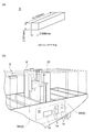
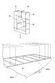
- the ship desulfurization apparatus concerning one Embodiment of this invention, it is a figure for demonstrating the crossing member provided in the storage space of an absorption tower. It is the schematic which showed the absorption tower of the desulfurization apparatus for ships concerning one Embodiment of this invention. It is the graph which showed the relationship between the shape (aspect ratio) of the internal space of the absorption tower main-body part in the desulfurization apparatus for ships concerning one Embodiment of this invention, and a desulfurization performance parameter. It is the table
- surface which showed the result of having examined the relationship between the shape (aspect ratio) of the internal space of the absorption tower main-body part in the desulfurization apparatus for ships concerning one Embodiment of this invention, and a desulfurization performance parameter.
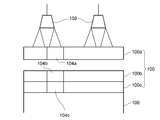
- FIG. 1 It is a mimetic diagram showing the case where the hull integrated desulfurization device concerning one embodiment is assembled into a hull structure. It is a mimetic diagram showing the case where the hull integrated desulfurization device concerning one embodiment is assembled into a hull structure. It is a mimetic diagram showing the case where the hull integrated desulfurization device concerning one embodiment is assembled into a hull structure. It is a mimetic diagram showing the case where the hull integrated desulfurization device concerning one embodiment is assembled into a hull structure.
- (A), (B) and (C) are schematic views showing several hull-integrated desulfurization apparatuses. It is process drawing which shows the assembly
- an expression indicating that things such as “identical”, “equal”, and “homogeneous” are in an equal state not only represents an exactly equal state, but also has a tolerance or a difference that can provide the same function. It also represents the existing state.
- expressions representing shapes such as quadrangular shapes and cylindrical shapes represent not only geometrically strict shapes such as quadrangular shapes and cylindrical shapes, but also irregularities and chamfers as long as the same effects can be obtained. A shape including a part or the like is also expressed.
- the expressions “comprising”, “comprising”, “comprising”, “including”, or “having” one constituent element are not exclusive expressions for excluding the existence of the other constituent elements. In the following description, the same components may be denoted by the same reference numerals and detailed description thereof may be omitted.
- FIG. 1 is a perspective view showing a ship according to an embodiment of the present invention.
- a ship 1 according to an embodiment of the present invention is, for example, a very large ship in which an exhaust gas amount of a main engine (exhaust gas amount at 100% load) exceeds 200,000 Nm 3 / h.
- the ship 1 is a very large container ship having a container loading capacity of 10,000 TEU or more called ULCS (Ultra Large Container Ship).
- the ship 1 includes a ship body 2, a residential area 4 that protrudes from the upper deck 3 at a position slightly forward from the center in the bow-stern direction, and a stern side of the residential area 4. And a steel plate structure 6 provided so as to protrude from the upper deck 3 at the position.
- the steel plate structure 6 is called a chimney or an engine casing.
- a plurality of transverse bulkheads 8 extending in the starboard-portal direction, which is a direction orthogonal to the bow-stern direction, are provided in the hold of the ship body 2 at intervals.
- the ship body 2 is divided into a plurality of regions whose basic unit is a length capable of accommodating the 40-foot container 9 along the longitudinal direction of the container in the bow-stern direction.
- FIG. 2A shows the dimensions of the 40-foot container 9.
- FIG.2 (b) is the figure which expanded and showed the periphery of the steel plate structure in the ship shown in FIG.
- the steel plate structure 6 is provided between a pair of adjacent horizontal partition walls 8A and 8B.
- An engine room 10 is formed inside the ship main body 2 that is vertically below the steel plate structure 6.
- the engine room 10 includes a main engine 12 including a marine diesel engine for imparting a propulsive force to the ship 1 and a main engine boiler for driving a main engine turbine, and various thermal demands in the ship 1.
- a plurality of auxiliary engines 14 composed of auxiliary boilers for responding to the demand, auxiliary engines for responding to electric power demand and the like are installed.
- the main engine 12 and the auxiliary engine 14 correspond to an exhaust gas generator mounted on the ship 1 according to one embodiment of the present invention.
- the steel plate structure 6 is a structure for releasing the exhaust gas discharged from the main engine 12 and the auxiliary engine 14 described above to the outside of the ship 1, and along the starboard-port side direction (width direction) of the ship 1. It is formed in a long cylinder shape having a longitudinal direction.
- a ship desulfurization apparatus 20 for desulfurizing exhaust gas discharged from the main engine 12 and the auxiliary engine 14 mounted on the ship 1 is disposed inside the steel plate structure 6.
- the inner width of the steel plate structure 6 (the length in the direction orthogonal to the longitudinal direction) is in the range of approximately 3-8 m.
- the length in the longitudinal direction of the steel plate structure 6 is relatively limited, and can be set in the range of 5 m to 20 m, for example.
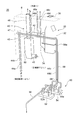
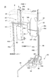
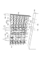
- FIG. 3 is a perspective view showing a marine vessel desulfurization apparatus according to an embodiment of the present invention.
- FIG. 4 is a perspective view showing a marine vessel desulfurization apparatus according to an embodiment of the present invention from an angle different from that in FIG. 3.
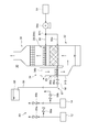
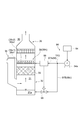
- the marine vessel desulfurization apparatus 20 according to an embodiment of the present invention is configured to absorb an exhaust tower 30 including an absorption tower main body 32 and exhaust gas discharged from the main engine 12 and the auxiliary engine 14. And an exhaust gas introducing device 40 for guiding to the absorption tower main body 32.
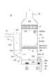
- FIG. 5 is a schematic view showing an absorption tower of a ship desulfurization apparatus according to an embodiment of the present invention.
- the absorption tower 30 includes an absorption tower main body portion 32, an exhaust gas introduction portion 34, and an exhaust gas outlet portion 36.
- the absorption tower main body 32 defines an internal space 31 having a longitudinal direction therein.
- An exhaust gas inlet 33 communicating with the internal space 31 (lower internal space 31b) is formed at one side end 39a in the longitudinal direction of the absorption tower main body 32.
- the exhaust gas introduced into the internal space 31 from the exhaust gas inlet 33 flows through the lower internal space 31b from the one side end 39a toward the other side end 39b, and then moves up the internal space 31. It flows.
- a filling layer 35 is formed in the internal space 31 at a position above the lower internal space 31b to separate the lower internal space 31b from the upper internal space 31c.
- a spraying device 38 for spraying a cleaning liquid (for example, seawater or fresh water) to the internal space 31 is disposed at a position above the packed bed 35. And it is comprised so that the sulfur content contained in exhaust gas may be removed by sprinkling cleaning liquid with respect to the exhaust gas which passes the filled layer 35, and making exhaust gas and cleaning liquid contact gas-liquid.
- a mist eliminator 37 that separates the upper side internal space 31c and the outlet side internal space 31d is disposed at a position above the upper side internal space 31c.
- the mist eliminator 37 is configured to remove moisture from the exhaust gas passing through the mist eliminator 37. Then, the exhaust gas that has passed through the mist eliminator 37 is discharged to the outside of the ship 1 from the exhaust gas deriving unit 36 connected to the uppermost part of the absorption tower main body 32 via the outlet side internal space 31d.
- the absorption tower main body 32 is formed with a storage space 31a in which the sprayed cleaning liquid sprayed on the exhaust gas guided to the internal space 31 is stored.
- the storage space 31 a is formed below the lower internal space 31 b and below the lower surface of the exhaust gas inlet 33.
- the desulfurization apparatus 20 for ships is further provided with the seawater supply apparatus 50 for supplying seawater with respect to the spraying apparatus 38 mentioned above.
- the seawater supply device 50 includes a wastewater dilution pump 52a, a seawater supply pump 54a, a drainage pipe 56, a seawater supply pipe 58, and a seawater discharge pipe 59. And it is comprised so that the seawater introduced into the inside of the ship main body 2 by the seawater supply pump 54a may be supplied to the spraying device 38 via the seawater supply pipe 58.
- the scrubber drainage discharged from the absorption tower 30 is diluted by the drainage dilution pump 52 a and drained to the outside of the ship 1 through the drainage pipe 56.
- each of the plurality of drainage dilution pumps 52 a is connected to a common first seawater suction box 52.
- each of the plurality of seawater supply pumps 54 a is connected to a common second seawater suction box 54.
- the internal space 31 of the absorption tower main body 32 is formed in a planar shape having a longitudinal direction along the introduction direction of the exhaust gas.
- the planar shape of the internal space 31 of the absorption tower main body 32 will be described in detail with reference to FIG.
- the symbol L indicates the length of the internal space 31 (length in the longitudinal direction)
- the symbol W indicates the width of the internal space 31 (length in the direction orthogonal to the longitudinal direction).
- Reference sign D is a converted diameter of a circular cross section having a cross-sectional area of the same size as a rectangular cross section having a cross-sectional area of length L and width W.
- the planar shape of the internal space 31 of the absorption tower main body 32 has a pair of long wall surfaces extending in parallel with each other, a pair of short wall surfaces extending in parallel with each other,
- the planar shape of the internal space 31 is not limited to a rectangular shape, and a rectangular shape or an elliptical shape having a longitudinal direction is used as long as the effect of the present invention is achieved. Further, it may be formed in an oval shape or the like.
- FIG. 6 is a diagram showing the examination result of the planar shape of the internal space of the absorption tower main body in the marine vessel desulfurization apparatus according to the embodiment of the present invention.
- placeability means ease of layout when placing the absorption tower 30 on the ship 1 for each planar shape
- Evaluation is performed with two items of “deflowability”, which means the uniformity of exhaust gas flow in the internal space 31 of the absorption tower 30.
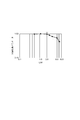
- FIG. 9 is a graph showing the relationship between the shape of the absorption tower internal space (aspect ratio L / W) and the desulfurization performance parameter in the ship desulfurization apparatus according to one embodiment of the present invention. In addition, in order to make the change of data stand out, it is expressed by logarithm.
- FIG. 10 is a table showing the results of examining the relationship between the shape (aspect ratio) of the internal space of the absorption tower main body and the desulfurization performance parameter in the ship desulfurization apparatus according to the embodiment of the present invention.
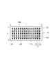
- FIG. 11 is a plan view for explaining the arrangement conditions of the watering nozzles in the internal space of the absorption tower body.
- the interference nozzle refers to a watering nozzle having watering nozzles adjacent to each other in four directions. That is, as shown in FIG. 11, a plurality of rows of water spray nozzles 71 are arranged in the internal space 31 of the absorption tower main body 32 along the longitudinal direction and the width direction, respectively, and the plurality of water spray nozzles 71 in a lattice shape as a whole. Is arranged, the watering nozzle 71b located inside the range 71A excluding the watering nozzle 71a arranged on the outermost peripheral side becomes the interference nozzle described above.
- the evaluation was made in four stages of ⁇ , ⁇ , ⁇ , and X in order from the higher desulfurization based on the following evaluation criteria. This is based on the idea that the higher the uniformity of the exhaust gas flow in the absorption tower 30, the better the desulfurization performance.
- the uniformity of the exhaust gas flow in the absorption tower 30 was evaluated from the above-described examination results based on the following examination conditions. As shown in FIG. 9, if the aspect ratio is 2 or less, the desulfurization performance parameter can be maintained at a substantially constant high level, and the uniformity of the exhaust gas flow in the absorption tower 30 can be maintained in a preferable state. .
- the desulfurization performance parameter gradually decreases as the aspect ratio increases, but the desulfurization performance parameter can be maintained at a high level.
- the aspect ratio exceeds 3 and is 6 or less the desulfurization performance parameter gradually decreases as the aspect ratio increases, but the desulfurization performance parameter can still be maintained at a relatively high level.
- the desulfurization performance parameter is drastically decreased for those having an aspect ratio exceeding 6, and the uniformity of the exhaust gas flow in the absorption tower 30 exhibits the required desulfurization performance. It is considered that the allowable range above is exceeded. Therefore, the upper limit of the aspect ratio is set to 6. (Evaluation criteria) ⁇ ...
- Inlet gas flow rate 2 to 20m / s
- Absorption tower flow velocity 1 to 5m / s
- Water sprinkling 30-200m 3 / m 2 ⁇ h
- “comprehensive evaluation” is performed based on the evaluation results for the two items of “placement” and “outflow” described above.
- “Comprehensive evaluation” the evaluation was made in three stages of “excellent”, “good”, and “good” in order from the highest overall evaluation based on the following evaluation criteria.
- the evaluations of “configuration” and “desulfurization” are in a trade-off relationship with each other, but by setting W: L within this range, the balance is excellent in both the configuration and deflowability.
- a good marine vessel desulfurization apparatus 20 can be provided.
- W: L 1: 2.0 and a range of 1: 3.0 or less were evaluated as “good” in the comprehensive evaluation.
- the above-described ship desulfurization apparatus 20 defines the internal space 31 having the longitudinal direction, and the internal space 31 (lower internal space) at the side end 39a on one side in the longitudinal direction.
- 31b includes an absorption tower 30 including an absorption tower main body 32 in which an exhaust gas inlet 33 communicating with 31b) is formed. That is, the internal space 31 of the absorption tower main body 32 is configured to have a longitudinal direction along the exhaust gas introduction direction. For this reason, since it is hard to produce a dead space compared with the conventional round (circular) absorption tower, it is excellent in the arrangement
- the absorption tower 30 having a planar shape having a longitudinal direction along the exhaust gas introduction direction provides a ship desulfurization apparatus 20 having excellent disposition characteristics to the ship 1 such as the above-described ultra-large container ship. can do.
- the risk of exhaust gas being discharged to the outside of the absorption tower without desulfurization is reduced compared to the case where the internal space of the absorption tower main body has a longitudinal direction along the direction orthogonal to the exhaust gas introduction direction. Can do.
- ratio (W: L) of the maximum width W and the maximum length L of the internal space 31 exceeds 1: 1.1, and 1: It is in the range below 6.0.
- the upper limit of the ratio (W: L) of the maximum width W and the maximum length L of the internal space 31 is 1: 6.0, the non-uniformity of the exhaust gas flow in the absorption tower 30 is It can be kept within a practically acceptable range as studied by the present inventors.
- the ratio (W: L) of the maximum width W to the maximum length L of the internal space 31 is 1: 1.5. It is super and the range of 1: 2.0 or less. According to such an embodiment, as described above, it is possible to provide a well-balanced marine vessel desulfurization apparatus 20 that is particularly excellent in arrangement and deflowability.
- the absorption tower 30 is configured so that the longitudinal direction of the internal space 31 of the absorption tower main body 32 is along the width direction of the ship 1. 1 is mounted. According to such an embodiment, the absorption tower 30 having a longitudinal direction along the width direction of the ship 1 is superior in arrangement to the ship 1 such as the above-described super-large container ship.
- An apparatus 20 can be provided.
- the absorption tower main body 32 can be configured to have a longitudinal direction along the width direction of the ship 1, and therefore, the longitudinal direction along the bow-stern direction of the ship 1. Since the bending stress acting on the absorption tower when the ship 1 rolls (rolling) can be reduced as compared with the absorption tower having the above, the absorption tower 30 having high resistance to rolling can be obtained.
- the ship 1 described above sends the exhaust gas discharged from the exhaust gas generator (the main engine 12 and the auxiliary engine 14) to the outside of the ship 1.
- emission Comprising: The steel plate structure 6 formed in the long cylinder shape which has a longitudinal direction along the width direction of the ship 1 is provided. And the absorption tower 30 is arrange
- the planar shape of the steel plate structure 6 is formed in a rectangular shape. Moreover, in some embodiments, the planar shape of the steel plate structure 6 may be formed in a rectangular shape having a longitudinal direction, an elliptical shape, an elliptical shape, or the like.
- the absorption tower 30 by arranging the absorption tower 30 inside the long cylindrical steel plate structure 6 having a longitudinal direction along the width direction of the ship 1, other various types mounted on the ship 1 are arranged. The influence on the arrangement plan of equipment and the like can be minimized. Therefore, retrofit with respect to the existing ship 1 becomes easy. Further, by disposing the absorption tower 30 inside the steel plate structure 6, for example, it is excellent in installation workability and maintainability compared to the case where the absorption tower 30 is disposed inside the ship 1 such as in the engine room 10. ing.
- the inside of the steel plate structure 6 described above is for recovering thermal energy from the exhaust gas discharged from the exhaust gas generator (main engine 12).
- An exhaust heat recovery device 60 is arranged.
- the absorption tower 30 is arranged side by side along the width direction of the exhaust heat recovery device 60 and the ship 1.
- the exhaust heat recovery device 60 includes an exhaust gas economizer that generates steam using thermal energy recovered from the exhaust gas.
- An exhaust gas inflow pipe 45 through which exhaust gas discharged from the main engine 12 flows is connected to the lower part of the exhaust heat recovery device 60, and an exhaust gas exhaust pipe 43 is connected to the upper part thereof.
- the exhaust gas introduction pipe 42 which will be described later, branches off from the exhaust gas exhaust pipe 43, so that the exhaust gas is introduced into the absorption tower 30.
- the exhaust gas inflow pipe 45, the exhaust gas exhaust pipe 43, and the exhaust gas introduction pipe 42 are a part of the exhaust gas introduction device 40 for guiding the exhaust gas discharged from the main engine 12 and the auxiliary engine 14 to the absorption tower main body 32. Part.
- the exhaust heat recovery device 60 is configured to have a longitudinal direction along the width direction of the ship 1, similarly to the absorption tower main body 32. Further, the internal space is formed in a rectangular shape in the horizontal cross section.
- the exhaust heat recovery device 60 and the absorption tower 30 are arranged inside the steel plate structure 6 by arranging the absorption tower 30 and the exhaust heat recovery device 60 along the width direction of the ship 1.
- the exhaust gas introduction device 40 can be configured simply.
- the exhaust heat recovery device 60 is formed in a rectangular shape having a longitudinal direction along the width direction of the ship 1, it is disposed inside the steel plate structure 6 having a longitudinal direction along the width direction of the ship 1. In this case, a dead space is hardly generated, and it can be efficiently arranged.
- the absorption tower 30 has one end 34a connected to the exhaust gas inlet 33 of the absorption tower main body 32 and the other end from the one end 34a. It further includes an exhaust gas introduction part 34 extending upward toward the end part 34b.
- the exhaust gas inlet 34 has a rectangular cross section, and the exhaust gas inlet 33 is also formed in a rectangular shape.
- the exhaust gas introduction part 34 includes an oblique part 34A extending obliquely upward from the exhaust gas introduction port 33 of the absorption tower main body part 32 and a vertical part 34B extending upward along the vertical direction from the end part of the oblique part 34A. And have.
- An exhaust gas introduction pipe 42 to be described later is connected to the end portion of the vertical portion 34B (the other end portion 34b of the exhaust gas introduction portion 34).
- the absorption tower disposed in the narrow space inside the steel plate structure 6 by connecting the exhaust gas introduction line (exhaust gas introduction pipe 42) to the other end 34b of the exhaust gas introduction part 34.
- Exhaust gas can be introduced to 30.
- the exhaust gas introduction device 40 described above is directed to the ship 1 from the exhaust heat recovery device 60 side toward the other end 34b of the exhaust gas introduction portion 34.
- the exhaust gas introduction pipe 42 In order to guide the exhaust gas discharged from the auxiliary engine 14 to the absorption tower main body 32 through the exhaust gas introduction pipe 42, and the exhaust gas introduction pipe 42 extending along the width direction of the exhaust gas.
- one end side of the exhaust gas introduction pipe 42 is connected to the above-described exhaust gas discharge pipe 43, and the other end side thereof is connected to the other end part 34b of the above-described exhaust gas introduction part 34.
- the exhaust gas introduction pipe 42 extends inside the steel plate structure 6 along the horizontal direction.
- an exhaust gas chimney 46 extending upward inside the steel plate structure 6 via the exhaust gas damper 47, an exhaust gas introduction pipe 42, Is connected.
- the exhaust gas damper 47 opens the flow path from the exhaust gas exhaust pipe 43 to the exhaust gas chimney 46, while the exhaust gas exhaust pipe 43 releases the exhaust gas.
- the flow path leading to the introduction pipe 42 is closed.
- the exhaust gas damper 47 opens the flow path from the exhaust gas exhaust pipe 43 to the exhaust gas introduction pipe 42, while the exhaust gas exhaust pipe 43 The flow path leading to the exhaust gas chimney 46 is closed.
- the exhaust gas introduction pipe 42 is connected to a plurality of auxiliary exhaust gas introduction pipes 44a to 44d through which exhaust gas discharged from the auxiliary engine 14 flows.
- a plurality of auxiliary exhaust gas exhaust pipes 48a to 48d are connected to each of the plurality of auxiliary exhaust gas introduction pipes 44a to 44d via an auxiliary machine exhaust gas damper (not shown).
- auxiliary machine exhaust gas damper not shown.
- a flow path leading from each of the plurality of auxiliary exhaust gas introduction pipes 44a to 44d to the plurality of auxiliary exhaust gas discharge pipes 48a to 48d is opened by an unillustrated exhaust gas damper.
- the flow path leading from each of the plurality of auxiliary equipment exhaust gas introduction pipes 44a to 44d to the exhaust gas introduction pipe 42 is closed. Further, for example, when the auxiliary engine 14 is operated, a flow path leading from each of the plurality of auxiliary exhaust gas introducing pipes 44a to 44d to the exhaust gas introducing pipe 42 is opened by an unillustrated exhaust gas damper, while a plurality of auxiliary exhaust pipes 14 are opened. The flow paths leading from the machine exhaust gas introduction pipes 44a to 44d to the plurality of auxiliary machine exhaust gas exhaust pipes 48a to 48d are closed.
- exhaust gas discharged from the main engine 12 and the auxiliary engine 14 can be introduced into the absorption tower 30 disposed in a narrow space inside the steel plate structure 6.
- the absorption tower body 32 includes a pair of longitudinal wall surfaces 32a and 32b extending in parallel with each other along the longitudinal direction of the interior space 31, and the interior space. And a pair of short wall surfaces 32c and 32d extending in parallel with each other along the short direction of 31.
- the planar shape of the internal space 31 of the absorption tower main body 32 is formed in a rectangular shape defined by the pair of long wall surfaces 32a and 32b and the pair of short wall surfaces 32c and 32d. Is done.
- the rectangular shape in the present embodiment includes those in which the corners of the rectangle are subjected to R processing and those in which the hunting processing is performed.
- the absorber tower main body 32 having such a rectangular internal space 31 is less likely to cause a dead space when placed in the ship, and therefore has excellent placement efficiency when placed in the ship.
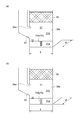
- FIG. 7 is a view for explaining a transverse member provided in the storage space of the absorption tower in the ship desulfurization apparatus according to the embodiment of the present invention.
- a storage space 31a in which the sprayed cleaning liquid sprayed on the exhaust gas guided to the internal space 31 is stored. Is formed.
- the absorption tower main body 32 connects a pair of long wall surfaces 32 a and 32 b (see FIG. 11) and crosses the storage space 31 a along the short direction of the internal space 31.
- a transverse member 70 is provided.
- the liquid level is swung by the cross member 70. Can be suppressed.
- strength of the absorption tower main-body part 32 which has the rectangular internal space 31 can also be improved by providing the crossing member 70 which connects such a pair of longitudinal wall surfaces 32a and 32b.
- the cross member 70 described above is formed of a cross beam member 70A having an elongated shape.
- the cross beam member 70A is made of, for example, an H-shaped steel having an H-shaped cross section, and at a substantially central position in the longitudinal direction of the internal space 31, a plurality of steps (three steps) are provided at intervals in the vertical direction. is set up.
- the cross beam member 70A may be a beam member having an I shape, an L shape, a T shape, and a cylindrical cross section.
- the above-mentioned sloshing suppression effect and the reinforcing effect of the absorption tower main body 32 can be realized by the cross beam member 70A having a long shape. Moreover, according to such embodiment, it is excellent especially in the reinforcement effect with respect to the absorption tower main-body part 32.
- FIG. 1 is a diagrammatic representation of the absorption tower main body part.
- the cross member 70 described above is formed of a weir plate member 70B having a flat plate shape.
- the dam member 70 ⁇ / b> B is made of a non-perforated plate in which no hole is formed on the plate surface, and is installed at a substantially central position in the longitudinal direction of the internal space 31.
- the barrier plate member 70B may be a perforated plate having a plurality of holes formed on the plate surface.
- the above-described effect of suppressing sloshing and the effect of reinforcing the absorber tower main body 32 can be realized by the weir plate member 70B having a flat plate shape. Moreover, according to such embodiment, it is especially excellent in the suppression effect of sloshing.
- the cross member 70 described above may include both the cross beam member 70A and the weir plate member 70B.
- the marine vessel desulfurization apparatus 20 is a spraying device 38 for spraying the cleaning liquid to the exhaust gas guided to the internal space 31 of the absorption tower main body 32.
- the spreading device 38A includes a longitudinal watering pipe 38a1 extending in parallel to each of the pair of longitudinal wall surfaces 32a and 32b (see FIG. 11) in the internal space 31 of the absorption tower main body 32, and a longitudinal dispersion. And a plurality of watering nozzles 38a2 provided in the water pipe 38a1.
- one longitudinal watering pipe 38 a 1 may be provided at a substantially central position in the short direction of the internal space 31. In some embodiments, a plurality of the longitudinal water spray pipes 38 a 1 may be provided at equal intervals in the short direction of the internal space 31.
- the distance from each of the plurality of watering nozzles 38a2 provided in the same longitudinal watering pipe 38a1 to the longitudinal wall surfaces 32a and 32b can be made constant.
- the cleaning liquid can be uniformly sprayed in the internal space 31, it is possible to suppress the influence of the problem that the spraying of the cleaning liquid becomes non-uniform due to the shaking (rolling, pitching, yawing, etc.) of the ship 1. it can.
- FIG. 8 is a schematic diagram showing an absorption tower of a marine vessel desulfurization apparatus according to an embodiment of the present invention.
- the absorption tower 30 shown in FIG. 8 differs from the absorption tower 30 shown in FIG. 5 described above only in the configuration of the spraying device 38. Therefore, the same reference numerals are given to the same components, and the description thereof is omitted.
- the marine vessel desulfurization apparatus 20 has a spraying device 38 (38 ⁇ / b> B) for spraying a cleaning liquid on the exhaust gas guided to the internal space 31 of the absorption tower main body 32. ).
- diffusion apparatus 38B extends in parallel with respect to each of a pair of short wall surface 32c, 32d (refer FIG. 11) in the internal space 31 of the absorption tower main-body part 32, and is arrange
- a short-side watering pipe 38b1 and at least one watering nozzle 38b2 provided in each of the plurality of short-side watering pipes 38b1 are provided.
- a plurality of watering nozzles 38b2 may be arranged at equal intervals in each of the plurality of short-side watering pipes 38b1. Moreover, in some embodiment, the installation position of the watering nozzle 38b2 arrange
- the spraying area of the watering nozzle 38b2 provided in each of the plurality of short-side watering pipes 38b1 can be set equal. Therefore, since the cleaning liquid can be uniformly sprayed in the internal space 31, it is possible to suppress the influence of the problem that the spraying of the cleaning liquid becomes non-uniform due to the shaking (rolling, pitching, yawing, etc.) of the ship 1. it can.
- the planar shape of the internal space 31 is not limited to a rectangular shape, and may be formed in a rectangular shape having a longitudinal direction, an elliptical shape, an oval shape, or the like as long as the effects of the present invention are achieved.
- FIG. 12 is a view for explaining the relationship between the planar shape and shape (aspect ratio L / W) of the internal space of the absorption tower main body in the marine vessel desulfurization apparatus according to the embodiment of the present invention.
- the internal space 31 of the absorption tower main body 32 includes an arc shape in at least a part of the planar shape. More specifically, in some embodiments, as shown in FIG.
- a pair of short wall surfaces extending in parallel with each other and a pair of short wall surfaces connected to each other. It is formed in a substantially rectangular shape defined by an arcuate wall surface.
- the internal space 31 of the absorption tower main body 32 is formed in an elliptical shape.
- a pair of longitudinal wall surfaces that exist in parallel to each other and a pair of arc-shaped wall surfaces that connect the ends of the pair of longitudinal wall surfaces It is formed in a defined oval shape.
- the above-described effects of the present invention can be achieved by providing the configuration in the above-described embodiments.
- the internal space of the absorption tower main body is configured to have a longitudinal direction along the exhaust gas introduction direction, a dead space is less likely to occur compared to a conventional round (circular) absorption tower, Excellent placement when placed on a ship.
- a desulfurization apparatus for ships excellent in arrangement for a certain type of super-large vessel such as ULCS the absorption tower having a planar shape having a longitudinal direction along the exhaust gas introduction direction is excellent in arrangement.
- the risk of exhaust gas being discharged to the outside of the absorption tower without desulfurization is reduced compared to the case where the internal space of the absorption tower main body has a longitudinal direction along the direction orthogonal to the exhaust gas introduction direction. Can do.
- the internal space 31 of the absorption tower main-body part 32 contains the circular arc shape in at least one part of planar shape, and the absorption tower main-body part 32 is a part containing the circular arc shape of the internal space 31. Since it is possible to provide a space that can be used such as passing a pipe through a portion corresponding to the outside of the housing, the layout can be improved.
- the wall surface (including the longitudinal wall surfaces 32a and 32b, the short wall surfaces 32c and 32d) of the absorption tower 30 including the absorption tower body 32, the exhaust gas introduction part 34, and the exhaust gas discharge part 36), and
- the material of the watering pipe 38c1 (including the longitudinal watering pipe 38a1 and the short-side watering pipe 38b1) and the watering nozzle 38c2 (including the watering nozzles 38a2 and 38b2) of the spraying device 38 is, for example, carbon steel (ordinary steel) such as SS400. It is.
- the anti-corrosion film by the anti-corrosion coating is given to the wall surface of the absorption tower 30, the water spray pipe of the sprinkling device 38, and the inner and outer surfaces of the water spray nozzle.
- the absorption tower 30 and the spraying device 38 are excellent in workability because carbon steel is used, and are excellent in corrosion resistance because they are provided with an anticorrosive coating with an anticorrosive paint.
- the invention according to this embodiment can also be applied to a rectangular absorption tower having an aspect ratio exceeding 1: 1.1 and outside the range of 1: 6.0 or less, and a round absorption tower.
- the wall surface of the absorption tower 30, the water spray pipe of the spraying device 38, and the inner and outer surfaces of the water spray nozzle are provided with anticorrosion lining such as resin lining or flake glass lining.
- the resin used for the resin lining is, for example, FRP.
- the absorption tower 30 and the spraying device 38 are excellent in corrosion resistance because they are provided with anticorrosion lining.
- the invention according to this embodiment can also be applied to a rectangular absorption tower having an aspect ratio exceeding 1: 1.1 and outside the range of 1: 6.0 or less, and a round absorption tower.
- the wall surface of the absorption tower 30 and the material of the water spray pipe and water spray nozzle of the spraying device 38 are, for example, high corrosion resistance stainless steel (stainless steel) such as SUS316L.
- the absorption tower 30 and the spraying device 38 are excellent in workability and corrosion resistance because high corrosion resistance stainless steel is used, and when an anticorrosion coating or anticorrosion lining with an anticorrosion paint is applied. Compared to this, the manufacturing time can be shortened, and the durability and maintenance are excellent.
- the invention according to this embodiment can also be applied to a rectangular absorption tower having an aspect ratio exceeding 1: 1.1 and outside the range of 1: 6.0 or less, and a round absorption tower.
- the material of at least a part of the absorption tower body 32 and the exhaust gas outlet 36 located above the absorption tower 30 is FRP (fiber reinforced plastic).
- FRP fiber reinforced plastic
- at least a part of the absorption tower main body 32 and the exhaust gas outlet 36 located above the absorption tower 30 are excellent in workability and corrosion resistance because FRP is used, and have anticorrosion properties.
- a manufacturing time can be shortened, and durability and maintenance are excellent.
- it can be made lightweight.
- the gravity center of the absorption tower 30 can be made into a low position by making the part with small load applied above the absorption tower 30 light, it is set as the absorption tower 30 which has high resistance with respect to rolling. Can do.
- the invention according to this embodiment can also be applied to a rectangular absorption tower having an aspect ratio exceeding 1: 1.1 and outside the range of 1: 6.0 or less, and a round absorption tower.
- FIG. 13 is a schematic view showing an absorption tower of a marine vessel desulfurization apparatus according to an embodiment of the present invention, and is a view seen from the direction A shown in FIG.
- the absorption tower 30 includes an internal space confirmation device for confirming the state of spraying of the cleaning liquid by the above-described spray device 38, the flow of exhaust gas in the internal space 31, and the like. 80 is included.
- the internal space confirmation device 80 includes a light-transmitting visual window 80 ⁇ / b> A that allows the interior of the internal space 31 to be visually recognized from the outside of the absorption tower 30 (absorption tower body 32).
- the viewing window 80A has a light transmissive member such as a glass surface, and is provided at a height where the upper end (top end) of the cleaning liquid sprayed by the spraying device 38 can be confirmed. More specifically, as shown in FIG. 13, the visual recognition window 80 ⁇ / b> A is provided at a height position below the mist eliminator 37 and above the spraying device 38 at the side end portion 39 b on the other side.
- one viewing window 80A is provided at a substantially central position in the width direction of the other side end 39b.
- a plurality of viewing windows 80A are provided at equal intervals in the width direction of the other side end 39b.
- the upper end (top end) of the cleaning liquid sprayed by the spraying device 38 is about 1 m above the watering nozzle 38c2 (including the watering nozzles 38a2 and 38b2) of the spraying device 38 in the absorption tower 30 including the packed bed 35 described above. positioned. Moreover, in the absorption tower 30 which is not provided with the packed bed 35 as shown in FIG. Some absorption towers not provided with the packed bed 35 are provided with a watering nozzle 38c2 facing downward to spray and to disperse gas and liquid using a tray.
- the invention according to some of the above-described embodiments and some of the embodiments described below can be applied to an absorption tower that does not include the packed bed 35.
- the visual recognition window 80A is disposed at a height position substantially the same as the upper end (top end) of the cleaning liquid. Further, in some other embodiments, as shown in FIG. 15, the viewing window 80 ⁇ / b> A is closer to the back side (opposite side to the exhaust gas inlet) of the side end portion 39 c in the short direction of the absorption tower body 32. It is provided in the position.
- the absorption tower 30 includes the internal space confirmation device 80 (viewing window 80A), thereby confirming the spraying state of the cleaning liquid by the spraying device 38, the flow of exhaust gas in the internal space 31, and the like. Can do.
- the spraying state by the spraying device 38 is poor, the spraying state by the spraying device 38 can be improved by performing processing such as cleaning of the watering nozzle 38c2 of the spraying device 38.
- the internal space confirmation device 80 (viewing window 80A) at a position closer to the back side (opposite side to the exhaust gas inlet) of the side end portion 39b on the other side in the longitudinal direction and the side end portion 39c in the short side direction, The flow of exhaust gas on the side opposite to the exhaust gas introduction port, which is difficult to confirm with the internal space confirmation device 80 (viewing window 80A) provided on the exhaust gas introduction port side, can be confirmed.
- the absorption tower 30 can confirm the angle of the cleaning liquid sprayed from the watering nozzle 38c2 of the spraying device 38 by including the internal space confirmation device 80 (viewing window 80A), and the sloshing situation from the angle of the cleaning liquid Can be grasped.
- the angle of the cleaning liquid can be easily confirmed by providing a mark such as a straight line extending in the vertical direction or the horizontal direction on the light transmissive member of the viewing window 80A. it can.
- the visual recognition window 80A can be reinforced by using the above-mentioned mark as a metal wire or the like.
- the invention according to this embodiment can also be applied to a rectangular absorption tower having an aspect ratio exceeding 1: 1.1 and outside the range of 1: 6.0 or less, and a round absorption tower.
- the internal space confirmation device 80 may be used for other purposes than the confirmation of the spraying state of the spraying device 38.
- the visual window 80A is provided on the exhaust gas inlet side to be used for confirming the flow of the exhaust gas on the exhaust gas inlet side, or the visual window 80A is provided at a height near the liquid surface of the storage space 31a in which the cleaning liquid is stored. It may be provided and used to check the storage space 31a.
- the invention according to this embodiment can also be applied to a rectangular absorption tower having an aspect ratio exceeding 1: 1.1 and outside the range of 1: 6.0 or less, and a round absorption tower.
- FIG. 14 is a schematic diagram showing an absorption tower of a marine vessel desulfurization apparatus according to an embodiment of the present invention, and an absorption tower (liquid column tower, spray tower, tray-type absorption tower, etc.) that does not include a packed bed. It is the figure which showed an example.
- the above-described marine vessel desulfurization apparatus 20 includes the absorption tower 30 including the above-described absorption tower main body 32 and the above-described viewing window 80A as illustrated in FIGS.
- the absorption tower 30 includes an absorption tower main body 32 configured so that the exhaust gas flows through the internal space 31, and a light-transmitting visual recognition that allows the internal space 31 to be visually recognized from the outside of the absorption tower main body 32. And a window 80A.
- an operator or the like can check the flow of exhaust gas flowing through the internal space 31 through the visual window 80 ⁇ / b> A.
- the internal space of the absorption tower body 32. 31 has a longitudinal direction.
- the absorption tower main-body part 32 mentioned above has the exhaust gas inlet 33 mentioned above connected to the internal space 31 in the edge part of the one side in the longitudinal direction of the internal space 31.
- the above-described viewing window 80 ⁇ / b> A is provided on the other side in the longitudinal direction of the internal space 31.
- the “other side” refers to a side farther from one side than the center in the longitudinal direction of the internal space 31.
- one viewing window 80 ⁇ / b> A is provided at a substantially central position in the width direction of the side end portion 39 b on the other side.
- a plurality of viewing windows 80A are provided at equal intervals in the width direction of the other side end 39b.
- the visual recognition window 80 ⁇ / b> A is provided at a position closer to the back side (opposite side to the exhaust gas introduction port) of the side end portion 39 c in the short direction of the absorption tower main body 32.
- the absorption tower main body 32 has the exhaust gas inlet 33 communicating with the internal space 31 at one end in the longitudinal direction of the internal space 31.
- the viewing window 80A is located on the other side in the longitudinal direction of the internal space 31, for example, on the back side of the side end 39b on the other side in the longitudinal direction or the side end 39c in the short side (opposite to the exhaust gas introduction port). Provided in position. An operator or the like can check the flow of the exhaust gas on the side opposite to the exhaust gas inlet 33, which is difficult to check with the visual window provided on the exhaust gas inlet 33 side, through the visual window 80A.
- the above-described spraying device 38 is provided in the ship desulfurization device 20 including the absorption tower 30 including the absorption tower body 32 and the viewing window 80A.
- the spraying device 38 has the above-mentioned watering nozzle 38c2 (including watering nozzles 38a2 and 38b2) capable of spraying the cleaning liquid into the internal space 31.
- the visual recognition window 80A mentioned above is arrange
- an operator or the like can spray the spraying state of the cleaning liquid by the water spray nozzle 38c2 through the visual recognition window 80A.
- the state of spraying the cleaning liquid by the device 38 can be confirmed. If the spraying condition of the cleaning liquid by the spraying device 38 is poor, the spraying condition by the spraying device 38 can be improved by performing processing such as cleaning of the watering nozzle 38c2.
- the above-described spraying device 38 is provided in the ship desulfurization device 20 including the absorption tower 30 including the absorption tower body 32 and the viewing window 80A.
- the spraying device 38 has the above-mentioned watering nozzle 38c2 (including watering nozzles 38a2 and 38b2) capable of spraying the cleaning liquid into the internal space 31.
- the watering nozzle 38c2 is configured to be able to spray the cleaning liquid upward.
- the cleaning liquid sprayed upward from the watering nozzle 38c2 rises to the upper end (top end) in the internal space 31 and then naturally falls.
- the visual recognition window 80A mentioned above is provided in the height position which can confirm the upper end (top end) of the washing
- the visual recognition window 80A is arranged at a height position substantially the same as the upper end (top end) of the cleaning liquid in design.
- the above-described viewing window 80A is disposed at a position where the upper end of the cleaning liquid sprayed by the spraying device 38 can be confirmed, the operator or the like can clean the cleaning liquid by the spraying device 38 via the viewing window 80A. It is possible to confirm whether or not the spraying condition is appropriate.
- the visual recognition window 80A is 0.5 m or more and 1.5 m or less above the water spray nozzle 38c2 of the spray device 38.
- the height is preferably 0.7 m or more and 1.3 m or less, more preferably 0.8 m or more and 1.2 m or less.
- the operator can confirm the upper end (top end) of the cleaning liquid sprayed by the spraying device 38 through the visual recognition window 80A.
- the viewing window 80A is 5 m or more and 15 m or less, preferably 7 m above the water spray nozzle 38c2 of the spraying device 38.
- the height is 13 m or less, more preferably 8 m or more and 12 m or less.
- the operator can confirm the upper end (top end) of the cleaning liquid sprayed by the spraying device 38 through the visual recognition window 80A.
- the absorption tower main body described above. 32 is configured such that the exhaust gas flows upward from below in the vertical direction, and has the above-described mist eliminator 37 provided above the watering nozzle 38c2 in the internal space 31. Further, as shown in FIGS. 13 and 14, the visual recognition window 80 ⁇ / b> A is disposed above the watering nozzle 38 c 2 and below the mist eliminator 37. In this case, the absorption tower main body 32 is configured such that the exhaust gas flows from the lower side to the upper side in the vertical direction.
- the visual recognition window 80 ⁇ / b> A is disposed above the watering nozzle 38 c 2 and below the mist eliminator 37. Since the exhaust gas is in gas-liquid contact with the cleaning liquid below the mist eliminator 37, even if the viewing window 80 ⁇ / b> A is provided above the mist eliminator 37, the spraying state of the cleaning liquid by the spraying device 38 cannot be confirmed.
- the viewing window 80A as described above, the operator can check the state of spraying the cleaning liquid by the spraying device 38 through the viewing window 80A.
- the operator confirms the upper end of the cleaning liquid sprayed by the spraying device 38 through the above-described visual window 80A, thereby cleaning the cleaning liquid. It is possible to confirm whether the spraying condition is appropriate.
- the invention according to some of the embodiments described above can also be applied to rectangular absorption towers having aspect ratios exceeding 1: 1.1 and outside the range of 1: 6.0 or less, and round absorption towers. is there.
- the filler (filler) in the packed bed 35 is for increasing the gas-liquid contact efficiency between the exhaust gas and the cleaning liquid inside the absorption tower 30.
- the absorption tower 30 absorbs the exhaust gas in an undesulfurized state when the packing stacked in the packed bed 35 moves and becomes non-uniform due to the shaking of the ship 1 (rolling, pitching, yawing, etc.). There is a risk of being discharged outside the tower.
- FIG. 15 is a perspective view (conceptual diagram) for explaining the filler in one embodiment of the present invention.
- a plurality of fillings 35 ⁇ / b> A in the filling layer 35 are arranged side by side in the vertical and horizontal directions.
- each of the fillings 35A is formed in a substantially rectangular parallelepiped shape.
- the filler 35A has outer diameter dimensions of, for example, 500 mm, 500 mm, and 100 mm.
- a plurality of the filling materials 35A are arranged side by side in the vertical and horizontal directions.
- the filling material 35A may not be laminated
- the fillings 35A in the packed bed 35 are arranged side by side at least in the lateral direction, movement due to the swaying of the ship 1 is restricted, and an uneven arrangement is prevented. Therefore, it is possible to reduce the risk that the exhaust gas is discharged to the outside of the absorption tower without being desulfurized.
- the invention according to this embodiment can also be applied to a rectangular absorption tower having an aspect ratio exceeding 1: 1.1 and outside the range of 1: 6.0 or less.
- the filling 35A includes at least a portion of regular packing, and in some other embodiments, the filling 35A includes at least a portion of irregular filling.
- regular packing represents a packing suitable for regular stacking
- regular packing represents a packing stacked irregularly when filling.
- the irregular packing has a larger required pressure loss than the regular packing, but can improve the dispersibility of the cleaning liquid. For this reason, according to the required pressure loss and the processing performance with the cleaning liquid, the packing 35A is selected to be either a regular packing or an irregular packing, or a ratio of the regular packing and the irregular packing.
- the invention according to this embodiment can also be applied to a rectangular absorption tower having an aspect ratio exceeding 1: 1.1 and outside the range of 1: 6.0 or less.
- the above-described marine vessel desulfurization apparatus 20 fills the absorption tower 30 including the absorption tower main body 32 described above, the above-described spraying apparatus 38, and the packed bed 35 provided in the above-described internal space 31.
- a filling 35A that is configured to bring the cleaning liquid into gas-liquid contact with the exhaust gas passing through the filling layer 35.
- the marine vessel desulfurization apparatus 20 includes a cleaning liquid having a large contact area on the surface of the filling 35A when the exhaust gas flows between the fillings 35A (gap) filled in the filling layer 35, and the filling.
- the exhaust gas whose flow is disturbed by the object 35A can be brought into gas-liquid contact.
- the gas-liquid contact efficiency between the cleaning liquid and the exhaust gas can be increased by the filler 35 ⁇ / b> A. Can be effectively removed.
- FIG. 16 is a schematic diagram for explaining the anticorrosion layer in one embodiment of the present invention, and is a schematic diagram showing an absorption tower of a ship desulfurization apparatus.
- the packed layer among the wall surfaces (including the long wall surfaces 32 a and 32 b and the short wall surfaces 32 c and 32 d) that define the internal space 31 of the absorption tower body 32.
- An anticorrosion layer 84 is formed on at least a part of the wall surfaces other than the wall surfaces that divide 35. And the anticorrosion layer 84 is not formed in the wall surface which divides the packed layer of the absorption tower main-body part 32.
- the anticorrosion layer 84 includes an anticorrosion film made of the above-described anticorrosion paint and the above-described anticorrosion lining.
- Absorption tower 30 (absorption tower body 32) is assembled by a block construction method. That is, the absorption tower 30 (absorption tower main body 32) is manufactured for each of several layered portions such as a circular slice, and is completed by stacking the layered portions and joining the portions together.
- the absorption tower main body 32 is divided into two parts by a two-dot chain line, and the first layered portion 32 ⁇ / b> A having a wall surface defining the packed bed 35 and the first layered shape in the absorption tower main body 32.
- a second layered portion 32B that is a portion below the portion 32A, a second layered portion 32B having a wall surface that partitions the storage space 31a and the lower side internal space 31b, and a first layered portion in the absorption tower main body 32
- the third layered portion 32C which is a portion above 32A, is completed by stacking the third layered portion 32C having a wall surface defining the upper side internal space 31c and connecting the portions together.
- the material of the second layered portion 32B, the third layered portion 32C, and the exhaust gas introducing portion 34 is, for example, carbon steel (ordinary steel) such as SS400.
- the anti-corrosion layer 84 is formed in the wall surface (inner wall surface) of the 2nd layer part 32B, the 3rd layer part 32C, and the waste gas introduction part 34.
- the material of the first layered portion 32A is, for example, high corrosion resistance stainless steel (stainless steel) such as SUS316L.
- the corrosion prevention layer 84 is not formed in the wall surface (inner wall surface) of 32 A of 1st layer parts.
- the wall surface (inner wall surface) that defines the internal space 31 of the absorption tower body 32 is a sulfur content contained in the exhaust gas, etc. There is a risk of corrosion.
- the above-described wall surface or the like may be corroded by the seawater.
- the filling 35 ⁇ / b> A moves due to the shaking of the ship and collides with the anticorrosion layer 84 that protects the wall surface defining the filling layer 35, thereby peeling or damaging the anticorrosion layer 84.
- the peeling or damage of the anticorrosion layer 84 may cause corrosion of the wall surface protected by the anticorrosion layer 84.
- the anticorrosion layer 84 is formed on the wall surface (inner wall surface) that defines the internal space 31 of the absorption tower main body 32, other than the wall surface that partitions the packed bed 35.
- the filling 35A may move due to the shaking of the ship and collide with the anticorrosion layer 84, and the anticorrosion layer 84 may be peeled off or damaged.
- the layered portion (the first layered portion 32A) surrounding the packed layer 35 in the absorption tower body 32 is made of a corrosion resistant material such as stainless steel, for example. By doing so, corrosion of the wall surface is suppressed.
- a marine vessel desulfurization apparatus 20 can suppress the corrosion of the wall surface defining the internal space 31 while preventing the anticorrosion layer 84 from being damaged by the filler 35A.
- the packing 35A is a rule. It is a filling.
- the marine desulfurization apparatus 20 can reduce the pressure loss of the exhaust gas as compared with the case where the filling 35A is an irregular packing because the filling 35A is a regular packing. The amount of exhaust gas treated can be increased. For this reason, the marine vessel desulfurization apparatus 20 using the regular packing as the packing 35A can be made smaller in size than the marine desulfurization apparatus 20 using the irregular packing as the packing 35A.
- the regular packing is less likely to move due to the shaking of the ship 1 than the irregular packing, and is less likely to be unevenly arranged due to the shaking of the ship 1. For this reason, the ship desulfurization apparatus 20 that uses the regular packing as the packing 35A is compared with the ship desulfurization apparatus 20 that uses the irregular packing as the packing 35A. The risk of being discharged can be reduced.
- the absorption tower main body 32 is The exhaust gas flows from the lower side to the upper side in the vertical direction.
- the spraying device 38 is configured to spray the cleaning liquid upward.
- the spraying device 38 is configured to spray the cleaning liquid upward.
- the cleaning liquid sprayed upward is dispersed at the upper end (the top) and then dispersed and present on the surface of, for example, the filling 35 ⁇ / b> A in the internal space 31 by falling down and falling.
- the sulfur content contained in the exhaust gas is removed by coming into gas-liquid contact with the cleaning liquid adhering to the surface of the filling 35A or the falling cleaning liquid. Is done.
- the invention according to some of the embodiments described above can also be applied to a rectangular absorption tower having an aspect ratio exceeding 1: 1.1 and outside the range of 1: 6.0 or less.
- the filling 35 ⁇ / b> A has a strength that allows at least the upper surface to cope with a human load. In this case, it can be used as a scaffold when installing components in the internal space 31 or during maintenance work.
- the invention according to this embodiment can also be applied to a rectangular absorption tower having an aspect ratio exceeding 1: 1.1 and outside the range of 1: 6.0 or less.
- the distance Hn between the packed bed 35 and the spreading device 38 shown in FIG. 13 is 2 m or more.
- the work space since the work space is secured, it is possible to improve the efficiency of installation and replacement work of the spraying device 38. Further, by increasing the size of the manhole connecting the internal space 31 and the outside according to the expansion of the work space, it is possible to further improve the efficiency of installation and replacement work of the spraying device 38.
- the invention according to this embodiment can also be applied to a rectangular absorption tower having an aspect ratio exceeding 1: 1.1 and outside the range of 1: 6.0 or less, and a round absorption tower.
- the pH adjusting agent 81 is disposed in at least a part of the storage space 31a. More specifically, as shown in FIG. 14, the pH adjuster 81 includes a lock-like alkaline agent 81 ⁇ / b> A that is spread on the inside of the net and spread on at least a part of the bottom surface of the storage space 31 a. In some embodiments, the lock-like alkaline agent 81A is spread over the entire bottom surface of the storage space 31a.
- the lock-like alkaline agent 81A is arrange
- the lock-like alkaline agent 81A by laying the lock-like alkaline agent 81A on the entire bottom surface of the storage space 31a, it is possible to reduce the wave splash at the time of the sloshing, and therefore it is possible to reduce the force applied to the absorption tower main body 32 at the time of the sloshing. Further, to reduce the wave splash at the time of sloshing, as shown in FIG.
- the absorption tower 30 when the sprayed cleaning liquid stored in the storage space 31a exceeds a certain amount, the absorption tower 30 is positioned on the downstream side. This is particularly useful when a partition 82 that flows into the seawater discharge pipe 59 is provided, and it is possible to suppress the sprayed cleaning liquid from flowing to the downstream side even though the sprayed cleaning liquid is less than a certain amount due to wave splattering during sloshing.
- the invention according to this embodiment can also be applied to a rectangular absorption tower having an aspect ratio exceeding 1: 1.1 and outside the range of 1: 6.0 or less, and a round absorption tower.
- the absorption tower 30 is provided between the storage space 31 a and the internal space 59 a of the seawater discharge pipe 59, and the partition 82 described above and the other side in the longitudinal direction.
- the lock-like alkaline agent 81A described above is spread over the entire bottom surface of the seawater water passing space 82a.
- the lock-like alkaline agent 81A is disposed in at least a part of the seawater flow space 82a, the lock-like alkaline agent 81A and seawater (cleaning liquid after low pH desulfurization containing sulfurous acid). ) Can be brought into contact with each other, so that the pH value can be increased by neutralizing seawater after low pH desulfurization.
- the invention according to this embodiment can also be applied to a rectangular absorption tower having an aspect ratio exceeding 1: 1.1 and outside the range of 1: 6.0 or less, and a round absorption tower.
- the hatch 83a which can be opened and closed is provided in the ceiling part 83 located above the seawater flow space 82a.
- the lock-like alkaline agent 81A in the seawater water-passing space 82a can be exchanged together with the net, so that the efficiency of exchanging the lock-like alkaline agent 81A can be improved.
- the invention according to this embodiment can also be applied to a rectangular absorption tower having an aspect ratio exceeding 1: 1.1 and outside the range of 1: 6.0 or less, and a round absorption tower.
- the absorption tower 30 does not include a packed bed 35 that separates the lower internal space 31b and the upper internal space 31c.
- a lower side space 31 b is below the spraying device 38, and an upper side internal space 31 c is above the spraying device 38.
- the spraying device 38 is disposed closer to the lower side of the absorption tower main body 32 than when the packed bed 35 is provided. For this reason, the upper side internal space 31c has a length along the vertical direction.
- the upper side internal space 31c has length along a perpendicular direction, the upper end (top end) of the cleaning liquid sprayed from the spraying device 38 can be made into a high position. For this reason, even if the absorption tower 30 is not provided with the packed bed 35, it is possible to reduce the risk that the exhaust gas is discharged to the outside of the absorption tower without being desulfurized.
- the invention according to this embodiment can also be applied to a rectangular absorption tower having an aspect ratio exceeding 1: 1.1 and outside the range of 1: 6.0 or less, and a round absorption tower.
- FIG. 17 is a schematic view showing an absorption tower of a marine vessel desulfurization apparatus according to an embodiment of the present invention, and is a view for explaining a wall surface reinforcing member and a partition wall.
- the absorption tower 30 is provided with a wall reinforcing member 92 inside the absorption tower main body 32.
- the wall surface reinforcing member 92 is fixed to one of the pair of long wall surfaces 32a and 32b and the pair of short wall surfaces 32c and 32d, and the inner wall 31 side from the fixed wall surface. And has a longitudinal direction along a wall surface fixed in the horizontal direction.
- the structural strength of the absorption tower 30 can be maintained by the wall surface reinforcing member 92.
- the invention according to this embodiment can also be applied to a rectangular absorption tower having an aspect ratio exceeding 1: 1.1 and outside the range of 1: 6.0 or less.
- the absorption tower 30 is disposed in the internal space 31 and extends along the longitudinal direction to divide the internal space 31 into a plurality of spaces.
- a partition wall 93 is provided.
- the structural strength of the absorption tower 30 can be maintained by the partition wall 93, and the exhaust gas can be rectified by the partition wall 93.
- the invention according to this embodiment can also be applied to a rectangular absorption tower having an aspect ratio exceeding 1: 1.1 and outside the range of 1: 6.0 or less.
- the absorption tower 30 has a pair of long wall surfaces 32a and 32b formed thicker than a pair of short wall surfaces 32c and 32d. In this case, the structural strength of the absorption tower 30 can be maintained by thickening the pair of longitudinal wall surfaces 32a and 32b.
- the invention according to this embodiment can also be applied to a rectangular absorption tower having an aspect ratio exceeding 1: 1.1 and outside the range of 1: 6.0 or less.
- the above-described ship desulfurization apparatus 20 includes the absorption tower 30 including the absorption tower body 32 described above, and the above-described spraying apparatus 38. I have.
- the spraying device 38 includes a watering pipe 38c1 (including a longitudinal watering pipe 38a1 and a short-side watering pipe 38b1) extending in the internal space 31, and a plurality of watering pipes arranged at predetermined intervals in the watering pipe 38c1.
- Nozzle 38c2 including watering nozzles 38a2 and 38b2).
- the marine vessel desulfurization apparatus 20 injects the cleaning liquid flowing through the water spray pipe 38c1 from each of the plurality of water spray nozzles 38c2 arranged at predetermined intervals in the water spray pipe 38c1, thereby causing the cleaning liquid to flow into the internal space 31. Can be dispersed evenly. Therefore, the marine vessel desulfurization apparatus 20 can suppress the influence of the problem that the spraying of the cleaning liquid becomes uneven due to the shaking (rolling, pitching, yawing, etc.) of the marine vessel 1.
- the invention according to this embodiment can also be applied to a rectangular absorption tower having an aspect ratio exceeding 1: 1.1 and outside the range of 1: 6.0 or less.
- the absorption tower 30 is formed in a long shape having a longitudinal direction, and further includes at least one support capable of supporting the water spray pipe 38c1 of the spraying device 38 from below.
- the support may be a round bar or a square bar, and may be flat or L-shaped.
- the support is arrange
- a some support is arrange
- the water spray pipe 38c1 may be fixed to the support.
- the water spray pipe 38c1 of the spraying device 38 since the water spray pipe 38c1 of the spraying device 38 is supported from below by the support, the water spray pipe 38c1 itself does not have to have a structural strength. Weight reduction can be performed. In addition, since the work can be performed in a state of being placed on the support at the time of installation and replacement of the water spray pipe 38c1, the efficiency of the installation work and replacement work can be improved. Moreover, when a support is arrange
- the invention according to this embodiment can also be applied to a rectangular absorption tower having an aspect ratio exceeding 1: 1.1 and outside the range of 1: 6.0 or less.
- the absorption tower 30 further includes a plurality of the above-described supports.
- the plurality of supports are arranged at regular intervals in the height direction of the absorption tower 30.
- the some support is arrange
- the plurality of supports can be used for installation of a work scaffold, for example, at the time of lining maintenance, it is possible to save the labor of the work scaffold and shorten the installation work time.
- a some support can be utilized freely for uses other than installation of a work scaffold, the maintainability of the absorption tower 30 can be improved.
- the ship 1 has a limited working period in the dog or a period in which the ship 1 can be anchored on the quay due to problems such as berthing costs. is important.
- the invention according to this embodiment can also be applied to a rectangular absorption tower having an aspect ratio exceeding 1: 1.1 and outside the range of 1: 6.0 or less.
- the water spray pipe 38c1 of the spraying device 38 has a structural strength that is not required to be supported from below by the support. In this case, a support may not be installed in the absorption tower 30. Moreover, in some embodiment, the water spray pipe 38c1 of the spreading device 38 has the intensity
- the water spray pipe 38c1 of the spraying device 38 is detachably fixed to the absorption tower main body 32 by fastening means such as bolting.
- fastening means such as bolting.
- the replacement work of the water spray pipe 38c1 can be easily performed. For this reason, the maintainability of the absorption tower 30 can be improved.
- the invention according to this embodiment can also be applied to a rectangular absorption tower having an aspect ratio exceeding 1: 1.1 and outside the range of 1: 6.0 or less. Further, the invention according to this embodiment can be applied to both an absorption tower including a support and an absorption tower not including a support.
- the watering nozzle 38c2 of the spraying device 38 is detachably fixed to the watering pipe 38c1 by fastening means such as bolting or screwing.
- fastening means such as bolting or screwing.
- the replacement work of the watering nozzle 38c2 can be easily performed. For this reason, the maintainability of the absorption tower 30 can be improved.
- the invention according to this embodiment can also be applied to a rectangular absorption tower having an aspect ratio exceeding 1: 1.1 and outside the range of 1: 6.0 or less. Further, the invention according to this embodiment can be applied to both an absorption tower including a support and an absorption tower not including a support.
- FIG. 18 is a view for explaining an exhaust gas cooling device of a marine vessel desulfurization device according to an embodiment of the present invention.
- the marine vessel desulfurization device 20 is disposed in the vertical portion 34 ⁇ / b> B of the exhaust gas introduction unit 34 and cools the exhaust gas introduced into the exhaust gas introduction unit 34.
- An exhaust gas cooling device 85 for spraying water is further provided.
- the exhaust gas cooling device 85 includes a water spray pipe 85a extending in a direction parallel to or perpendicular to a pair of wall surfaces located on both sides in the width direction of the exhaust gas introduction section 34, and a plurality of water pipes 85a.
- a cooling water nozzle 85b is a view for explaining an exhaust gas cooling device of a marine vessel desulfurization device according to an embodiment of the present invention.
- the marine vessel desulfurization device 20 is disposed in the vertical portion 34 ⁇ / b> B of the exhaust gas introduction unit 34 and cools the exhaust gas introduced into the exhaust gas introduction unit 34.
- each of the watering pipe 85a and the cooling water nozzle 85b is the watering pipe 38c1 (including the longitudinal watering pipe 38a1 and the short-side watering pipe 38b1) and the watering nozzle 38c2 (including the watering nozzles 38a2 and 38b2). Since they have the same configuration as each of them, descriptions on common matters are omitted.
- induced in the waste gas introduction part 34 can be lowered
- the marine absorption tower 30 has a higher temperature of the exhaust gas introduced into the exhaust gas introduction portion 34 than the onshore absorption tower in which a heat exchanger for exchanging heat of the exhaust gas is arranged on the upstream side. It is. More specifically, the absorption tower for land is cooled to about 170 ° C. before being led into the exhaust gas introduction section 34, but the absorption tower for ships has an exhaust gas of about 300 ° C. in the exhaust gas introduction section 34. Is directly guided.
- the anticorrosion lining (anticorrosion layer 84) is given to the exhaust gas introduction part 34 of the absorption tower 30 for ships, there exists a possibility that an anticorrosion lining may be damaged by the heat
- the spraying by the spraying device 38 of the absorption tower main body 32 cannot cool the inlet side of the exhaust gas introducing section 34. Therefore, the exhaust gas cooling device 85 is particularly useful when provided in the marine absorption tower 30.
- the volume of the exhaust gas guided into the exhaust gas introduction part 34 can be reduced by spraying the cooling water, a large amount of exhaust gas can be treated in the absorption tower 30.
- the invention according to this embodiment can also be applied to a rectangular absorption tower having an aspect ratio exceeding 1: 1.1 and outside the range of 1: 6.0 or less, and a round absorption tower.
- the exhaust gas cooling device 85 is connected to the seawater supply pipe 58 of the seawater supply apparatus 50 via a cooling water supply pipe 58a (cooling water pipe) branched at the branch point TP1, as shown in FIG.
- the seawater introduced into the ship body 2 is supplied by the seawater supply pump 54a.
- the seawater supply device 50 can be shared with the spraying device 38, it is possible to prevent the ship desulfurization device 20 from becoming large and having a complicated structure.
- the invention according to this embodiment can also be applied to a rectangular absorption tower having an aspect ratio exceeding 1: 1.1 and outside the range of 1: 6.0 or less, and a round absorption tower.
- the marine vessel desulfurization device 20 further includes an emergency cooling device 87 for supplying emergency cooling water to the exhaust gas cooling device 85 in an emergency, as shown in FIG.
- “emergency” refers to, for example, a case where the exhaust gas is heated in the water tower 30 without being sprayed by the spraying device 38.
- the emergency cooling device 87 is connected to the emergency tank 86 for storing the emergency cooling water, the sprinkling pipe 85a and the emergency tank 86 of the exhaust gas cooling device 85, and the emergency water from the emergency tank 86 is connected to the sprinkling pipe 85a.
- an emergency cooling water line 88 for supplying cooling water.
- the emergency cooling device 87 does not require a power source and is configured to be operable even when the power source is lost.
- the emergency cooling device 87 may include a pressurized tank as the emergency tank 86, and the emergency tank 86 is disposed at a high position so that the emergency cooling water is supplied to the sprinkling pipe 85a due to the height difference. It may be a thing.
- an emergency opening / closing valve 90 may be provided in the emergency cooling water pipe 88.
- the emergency on-off valve 90 is configured to close while electricity is supplied from the power source and to open when power is lost.
- the emergency cooling device 87 that can operate even when the power supply is lost can spray the cooling water in the event of an emergency, thereby reducing the temperature of the exhaust gas guided into the absorption tower 30. For this reason, since the rise in the temperature in the absorption tower 30 can be suppressed, it is possible to prevent the absorption tower 30 from being damaged by a high temperature.
- the invention according to this embodiment can also be applied to a rectangular absorption tower having an aspect ratio exceeding 1: 1.1 and outside the range of 1: 6.0 or less, and a round absorption tower.
- the marine vessel desulfurization device 20 further includes an emergency bypass device 89 for causing the exhaust gas to bypass the absorption tower 30 in an emergency, as shown in FIG.
- the emergency bypass device 89 includes a switching damper 89 a provided in the middle of the exhaust gas pipe connected to the main engine 12 and the absorption tower 30, and an exhaust gas pipe connected to the auxiliary engine 14 and the absorption tower 30. And a switching damper 89b provided on the way. In the normal state, the switching damper 89a and the switching damper 89b have the bypass flow path closed and the flow path leading to the absorption tower 30 opened. In an emergency, the switching damper 89a and the switching damper 89b open the detour channel and close the channel leading to the absorption tower 30.
- the emergency bypass device 89 can bypass the exhaust gas by detouring the exhaust gas in an emergency. For this reason, since the temperature rise in the absorption tower 30 can be suppressed in an emergency, it is possible to prevent the absorption tower 30 from being damaged due to a high temperature.
- the invention according to this embodiment can also be applied to a rectangular absorption tower having an aspect ratio exceeding 1: 1.1 and outside the range of 1: 6.0 or less, and a round absorption tower.
- FIG. 19 is a view for explaining an exhaust gas cooling device of a ship desulfurization apparatus according to an embodiment of the present invention.
- the above-described ship desulfurization apparatus 20 has an exhaust gas inlet connected to the absorption tower body 32 and the exhaust gas inlet 33 in which the above-described exhaust gas inlet 33 is formed.
- the above-described exhaust gas cooling device 85 capable of spraying cooling water to the exhaust gas introduced into the exhaust gas introduction unit 34.
- the exhaust gas cooling device 85 has the cooling water nozzle 85b comprised so that a cooling water may be ejected toward the upstream of the flow direction of waste gas.
- the marine vessel desulfurization apparatus 20 disperses the cooling water by the exhaust gas cooling device 85 with respect to the exhaust gas introduced into the exhaust gas introduction unit 34, so that the exhaust gas introduced into the exhaust gas introduction unit 34.
- the temperature of the exhaust gas inlet 34 can be suppressed from rising.
- the ship desulfurization apparatus 20 is introduced with exhaust gas having a temperature higher than that of a land-based desulfurization apparatus provided at a power plant. It becomes important.
- the volume of the exhaust gas introduced into the exhaust gas introduction part 34 can be reduced by spraying the cooling water with the exhaust gas cooling device 85, a large amount of exhaust gas can be processed in the absorption tower 30.
- the cooling water nozzle 85b of the exhaust gas cooling device 85 ejects the cooling water toward the upstream side in the flow direction of the exhaust gas, the temperature of the exhaust gas introduced into the exhaust gas introduction unit 34 before reaching the cooling water nozzle 85b. It is possible to prevent the cooling water nozzle 85b from being damaged by the heat of the exhaust gas.
- the above-described exhaust gas cooling device 85 includes a first exhaust gas cooling device 85C configured to supply seawater as cooling water from the seawater supply pump 54a, A first exhaust gas cooling device 85D configured to supply, for example, industrial water as emergency cooling water from the emergency cooling device 87. That is, the marine vessel desulfurization device 20 may have a dedicated device or piping for injecting emergency cooling water from the cooling water nozzle 85b.
- the cooling water described above is seawater introduced into the interior of the ship 1.
- the ship desulfurization apparatus 20 can suppress the consumption of water such as industrial water required during the navigation of the ship 1 by using the seawater introduced into the ship 1 as the cooling water. it can.
- the above-described marine vessel desulfurization apparatus 20 includes an absorption tower 30 including the absorption tower main body 32 in which the exhaust gas inlet 33 described above is formed and the exhaust gas inlet 34 connected to the exhaust gas inlet 33. And an exhaust gas cooling device 85 having the above-described cooling water nozzle 85b. And the exhaust gas introduction part 34 is comprised so that exhaust gas may flow toward the downward direction from the upper direction in a perpendicular direction. Further, the cooling water nozzle 85b is configured to inject cooling water upward.
- the cooling water nozzle 85b is configured to inject the cooling water upward.
- the cooling water jetted upward comes into contact with the exhaust gas above the cooling water nozzle 85b, drops the temperature of the exhaust gas, and then drops onto the cooling water nozzle 85b.
- the cleaning liquid dropped on the cooling water nozzle 85b can wash away sulfurous acid and salt adhering to the cooling water nozzle 85b. Moreover, it can suppress that sulfurous acid and a salt adhere to the cooling water nozzle 85b by hold
- the above-described marine vessel desulfurization apparatus 20 includes an absorption tower 30 including the absorption tower main body 32 in which the exhaust gas inlet 33 described above is formed and the exhaust gas inlet 34 connected to the exhaust gas inlet 33.
- the exhaust gas cooling device 85 described above includes the above-described cooling water nozzle 85b, the above-described cooling water supply pipe 58a (cooling water conduit) for supplying cooling water to the cooling water nozzle 85b, and the cooling water supply pipe 58a ( A cooling water control valve 94 provided in the (cooling water pipeline), which can control the amount of cooling water sprayed from the cooling water nozzle 85b.
- the pressure of the cooling water on the primary side that is upstream of the cooling water control valve 94 (seawater supply pump 54a side) in the cooling water pipeline is a variable factor such as the height of the draft line and the number of operating seawater supply pumps 54a (pumps). If the cooling water control valve 94 is not provided, the amount of cooling water sprayed from the cooling water nozzle 85b varies greatly due to the above-described variation factors, and thus the coolant is introduced into the exhaust gas introduction unit 34. There is a risk that the exhaust gas will be insufficiently cooled. On the other hand, according to the above configuration, the exhaust gas cooling device 85 is introduced into the exhaust gas introduction unit 34 by controlling the amount of cooling water sprayed from the cooling water nozzle 85b by the cooling water control valve 94. It is possible to sufficiently cool the exhaust gas.
- the above-described cooling water control valve 94 has an opening degree such that the pressure of the cooling water on the secondary side, which is the downstream side (cooling water nozzle 85b side) of the cooling water control valve 94, is constant. Is adjusted to control the amount of cooling water sprayed from the cooling water nozzle 85b.
- a pressure gauge is connected to the downstream side cooling water supply pipe 58b.
- 95 fluid pressure detector
- the pressure gauge 95 is configured to be able to detect the pressure of the cooling water in the downstream side cooling water supply pipe 58b.
- the cooling water control valve 94 is configured to adjust the opening so that the pressure detected by the pressure gauge 95 becomes constant.
- the coolant pressure on the downstream side (rear stream side) of the coolant control valve 94 is made constant by the coolant control valve 94, the coolant pressure when ejected from the coolant nozzle 85b is also constant.
- the cooling water nozzle 85b always sprays a certain amount or more of cooling water at a certain height. In this case, since a certain amount or more of cooling water can always be sprayed from the cooling water nozzle 85b, the exhaust gas guided into the exhaust gas introduction unit 34 can be continuously cooled.
- the pressure gauge 95 continuously detecting the pressure of the cooling water in the downstream side cooling water supply pipe 58b by the pressure gauge 95, for example, continuously detecting the temperature of the cooling water in the downstream side cooling water supply pipe 58b by a thermometer, etc. Detection is easier than other detection devices. Further, since the pressure on the primary side fluctuates greatly as described above, it is not suitable as an index for adjusting the opening degree of the cooling water control valve 94. For this reason, the cooling water sprayed from the cooling water nozzle 85b by the cooling water control valve 94 is used by using the pressure on the secondary side detected by the pressure gauge 95 as an index for adjusting the opening degree of the cooling water control valve 94. It is possible to easily control the application amount.
- the invention according to some of the embodiments described above can also be applied to a rectangular absorption tower having an aspect ratio exceeding 1: 1.1 and outside the range of 1: 6.0 or less.
- the marine vessel desulfurization device 20 includes the above-described emergency cooling device 87, the above-described emergency bypass device 89, and the exhaust gas for monitoring the temperature of the exhaust gas discharged from the outlet of the absorption tower 30. And a temperature monitoring device.
- the exhaust gas temperature monitoring device includes a temperature sensor. When the exhaust gas temperature monitoring device detects a high temperature, the emergency cooling device 87 operates to spray cooling water, and the emergency bypass device 89 operates to cause the exhaust gas to flow into the absorption tower 30. Is prevented.
- the exhaust gas temperature monitoring device may monitor the temperature of the exhaust gas inside the absorption tower 30.
- the invention according to this embodiment can also be applied to a rectangular absorption tower having an aspect ratio exceeding 1: 1.1 and outside the range of 1: 6.0 or less, and a round absorption tower.
- hypochlorite is added to water such as cleaning liquid and cooling water used in the ship desulfurization apparatus 20.
- bioadhesion can be prevented by adding hypochlorite, so that biocorrosion can be suppressed.
- seawater is used for boiler condensers and the like, and no biocorrosion countermeasures are used exclusively for the desulfurization equipment.
- the invention according to this embodiment can also be applied to a rectangular absorption tower having an aspect ratio exceeding 1: 1.1 and outside the range of 1: 6.0 or less, and a round absorption tower.
- the exhaust gas inlet 34 has a double outer wall structure.
- the exhaust gas introduction part 34 and the cooling water nozzle 85b that contact the exhaust gas first in the absorption tower 30 are easily corroded, and even if the exhaust gas introduction part 34 and the cooling water nozzle 85b are damaged by corrosion, It is possible to prevent the exhaust gas from leaking outside.
- the ship 1 is provided in the steel plate structure 6 in which the absorption tower 30 is a closed space, leakage of exhaust gas is dangerous, and this risk can be avoided.
- the invention according to this embodiment can also be applied to a rectangular absorption tower having an aspect ratio exceeding 1: 1.1 and outside the range of 1: 6.0 or less, and a round absorption tower.
- the exhaust gas introduction unit 34 includes a leak detection device for detecting gas leak or liquid leak due to corrosion such as lining, and the gas leak or liquid leak due to corrosion flows out of the absorption tower 30. It is configured to let you. In this case, gas leakage or liquid leakage due to corrosion in the exhaust gas introduction unit 34 can be sensed, and gas leakage or liquid leakage due to corrosion can flow out of the absorption tower 30.
- the invention according to this embodiment can also be applied to a rectangular absorption tower having an aspect ratio exceeding 1: 1.1 and outside the range of 1: 6.0 or less, and a round absorption tower.
- the marine vessel desulfurization apparatus 20 further includes a cooling tower as a pre-process of the absorption tower 30.
- a cooling tower is provided as a pre-process of the absorption tower 30, impurities such as heavy metals can be removed in the cooling tower.
- a water circulation type cooling tower is used. In this case, the amount of water required during the navigation of the ship 1 can be suppressed.
- industrial water for cooling is used instead of seawater in the water circulation type cooling tower. In this case, as compared with seawater that may contain unspecified impurities, it is only necessary to remove specific impurities such as heavy metals, so that waste water treatment can be easily performed.
- the invention according to this embodiment can also be applied to a rectangular absorption tower having an aspect ratio exceeding 1: 1.1 and outside the range of 1: 6.0 or less, and a round absorption tower.
- the marine vessel desulfurization apparatus 20 further includes a heat exchanger that recovers heat from the exhaust gas and heats the exhaust gas after the desulfurization treatment.
- the heat exchanger includes a rotary heat exchanger, such as a Jungstrom type, or a stationary heat exchanger.
- the heat exchanger includes a gas gas heater (GGH). That is, the heat exchanger includes a heat recovery unit that recovers heat from the exhaust gas, and a reheater that heats the exhaust gas by heat sent from the heat recovery unit.
- GGH gas gas heater
- the diffusibility of exhaust gas can be improved.
- the invention according to this embodiment can also be applied to a rectangular absorption tower having an aspect ratio exceeding 1: 1.1 and outside the range of 1: 6.0 or less, and a round absorption tower.
- the ship 1 is provided with a heat medium circulation type non-leak gas gas heater.
- heat recovery can be performed from the exhaust gas discharged from the main engine 12 and the auxiliary engine 14 in the engine room 10 by the non-leak gas gas heater. Then, by using the recovered heat to heat the steam used in the ship 1 or to heat source equipment such as heating, the fuel used in the ship 1 can be reduced.
- the invention according to this embodiment can also be applied to a rectangular absorption tower having an aspect ratio exceeding 1: 1.1 and outside the range of 1: 6.0 or less, and a round absorption tower.
- the marine vessel desulfurization apparatus 20 is configured so that the flange joint of the pipe joint portion is reduced. In this case, the efficiency of the pipe joining work can be improved.
- the invention according to this embodiment can also be applied to a rectangular absorption tower having an aspect ratio exceeding 1: 1.1 and outside the range of 1: 6.0 or less, and a round absorption tower.
- the ship desulfurization apparatus 20 can be fixed to the absorption tower 30 or the exhaust heat recovery apparatus 60 by welding, for example, among equipment and parts such as piping, and is transported to the ship 1 by a lifting machine or the like. It is fixed in advance during prefabrication, which will be described later, which is a pre-process of work. In this case, it is possible to prevent the positions of the instruments and parts from shifting when transported to the ship 1. Moreover, since the assembly work in the ship 1 can be reduced, the efficiency of the work of attaching the ship desulfurization device 20 to the ship 1 can be improved.
- the invention according to this embodiment can also be applied to a rectangular absorption tower having an aspect ratio exceeding 1: 1.1 and outside the range of 1: 6.0 or less, and a round absorption tower.
- the piping in the marine vessel desulfurization apparatus 20 is a resin piping, and the end portion is configured to be connectable by a socket. Moreover, in some embodiments, the resin in the socket in the ship desulfurization apparatus 20 and the pipe connecting the pipes is wound. In these cases, the corrosion resistance of the piping and socket can be improved.
- rubber pipes are used at locations where the pipes are connected to each other so that the pipes can be easily aligned. In this case, since the pipes can be easily aligned, the efficiency of pipe installation work can be improved.
- the invention according to this embodiment can also be applied to a rectangular absorption tower having an aspect ratio exceeding 1: 1.1 and outside the range of 1: 6.0 or less, and a round absorption tower.
- the navigation resistance of the ship 1 can be reduced by the foam.
- emitted out of a ship from the ship desulfurization apparatus 20 can be raised by generating a bubble in the ship bottom drain part vicinity.
- the wastewater discharged out of the ship from the ship desulfurization apparatus 20 is diluted by being mixed with the seawater outside the ship, and has a pH higher than that of the wastewater immediately after being discharged from the ship desulfurization apparatus 20. The value has risen to some extent.
- the invention according to this embodiment can also be applied to a rectangular absorption tower having an aspect ratio exceeding 1: 1.1 and outside the range of 1: 6.0 or less, and a round absorption tower.
- a land-based desulfurization device provided in a power plant is assembled by a block method or a panel method.
- the ship desulfurization apparatus is not easy to assemble because the aspect ratio of the water tower may be different. And it is not realistic to assemble the ship desulfurization apparatus on the ship where the work space and work time on the ship are limited. For this reason, the assembly of the ship desulfurization apparatus requires three operations: assembly work on land, suspension work on the ship, and installation work on the ship. And in order to reduce the working time on a ship, it is necessary to reduce the installation work in a ship.
- the desulfurization apparatus for ships is suspended in a ship with a lifting machine etc., the structure which can be installed safely is needed.
- the absorption tower 30 is formed in a prefabricated form at a nearby factory or an assembly place such as a vacant land, and the above-described prefabricated absorption tower 30 is suspended and transported by a hoisting machine or the like. , Installed on the ship 1.
- the absorption tower 30 is formed in a prefabricated shape before being installed on the ship 1, installation work on the ship 1 can be reduced and work time on the ship 1 can be reduced.
- the invention according to this embodiment can also be applied to a rectangular absorption tower having an aspect ratio exceeding 1: 1.1 and outside the range of 1: 6.0 or less.
- the wall which constitutes absorption tower 30, and piping arranged around absorption tower 30 are being fixed integrally.
- the pipe can easily maintain the level.
- the absorption tower 30 can make installation work easy and can shorten the work time concerning installation work.
- the invention according to this embodiment can also be applied to a rectangular absorption tower having an aspect ratio exceeding 1: 1.1 and outside the range of 1: 6.0 or less.
- the absorption tower 30 is assembled by a block method.
- the absorption tower 30 is manufactured for each of several layered portions such as a round slice, and is completed by stacking the layered portions and connecting the portions together.
- the absorption tower 30 is completed by stacking the respective layered parts and connecting the parts together, so that the working time at the assembly site can be shortened.
- the block method requires labor and time for transportation compared to the panel method.
- the invention according to this embodiment can also be applied to a rectangular absorption tower having an aspect ratio exceeding 1: 1.1 and outside the range of 1: 6.0 or less.
- the absorption tower 30 is assembled by a panel method. That is, the absorption tower 30 has a wall surface, a bottom surface, and the like configured by a plate-like member (panel), and is completed by installing the above-described plate-like member on a column, a beam, or the like.
- the absorption tower 30 is composed of plate-like members, columns, beams, and the like. Therefore, it is only necessary to transport these plate-like members, columns, beams, etc. to the place where they are assembled. The member can be easily transported.
- the panel method requires more work at the assembly site than the block method.
- the invention according to this embodiment can also be applied to a rectangular absorption tower having an aspect ratio exceeding 1: 1.1 and outside the range of 1: 6.0 or less.
- the marine vessel desulfurization apparatus 20 has at least one major part modularized. In this case, since at least one main part is modularized, the marine vessel desulfurization apparatus 20 can shorten the working time at the assembly site.
- the invention according to this embodiment can also be applied to a rectangular absorption tower having an aspect ratio exceeding 1: 1.1 and outside the range of 1: 6.0 or less.
- the absorption tower 30 is configured to be self-supporting.
- the above-described water spray pipe (including the longitudinal water spray pipe 38 a 1, the short water spray pipe 38 b 1, and the water spray pipe 85 a) is inserted into the self-supporting absorption tower 30 and installed inside the absorption tower 30.
- the above-described packing 35 ⁇ / b> A is also inserted into the self-supporting absorption tower 30 and installed inside the absorption tower 30.
- the absorption tower 30 is configured to be able to stand on its own, it is possible to easily insert and dispose the above-described water sprinkling pipe and packing 35 ⁇ / b> A inside the absorption tower 30.
- Such an absorption tower 30 can shorten the working time at the assembly site.
- the invention according to this embodiment can also be applied to a rectangular absorption tower having an aspect ratio exceeding 1: 1.1 and outside the range of 1: 6.0 or less.
- a plurality of the longitudinal watering pipes 38a1 described above are provided at equal intervals in the short direction of the internal space 31, and each of the plurality of longitudinal watering pipes 38a1 is arranged in a staggered manner. And the adjacent longitudinal watering pipes 38a1 are arranged so that their height positions are different from each other.
- the short-side watering pipes 38b1 described above are provided at equal intervals in the longitudinal direction of the internal space 31, and each of the plurality of short-side watering pipes 38b1 is staggered. It arrange
- a plurality of the above-described water spray pipes 85a are provided at equal intervals in the exhaust gas introduction unit 34, and each of the plurality of water spray pipes 85a is arranged in a staggered manner and adjacent to each other. It arrange
- the invention according to this embodiment can also be applied to a rectangular absorption tower having an aspect ratio exceeding 1: 1.1 and outside the range of 1: 6.0 or less.
- the watering nozzle 38a2 is integrated with the longitudinal watering pipe 38a1 without using bolts or the like.
- the watering nozzle 38b2 is integrated with the short-side watering pipe 38b1 without using bolts or the like.
- the cooling water nozzle 85b is integrated with the water spray pipe 85a without using bolts or the like. In these cases, high strength can be achieved by integrating the watering nozzle with the watering pipe.
- seawater desulfurization does not have a worries about clogging, it is possible to make a watering nozzle into an integrated structure with a watering pipe.
- the invention according to this embodiment can also be applied to a rectangular absorption tower having an aspect ratio exceeding 1: 1.1 and outside the range of 1: 6.0 or less.
- a land-based desulfurization apparatus provided in a power plant is assembled by a block method or a panel method at an installation site.
- the ship desulfurization apparatus is not easy to assemble because the aspect ratio of the water tower may be different. And it is not realistic to assemble the ship desulfurization apparatus on the ship where the work space and work time on the ship are limited. For this reason, after assembling the desulfurization apparatus on land, it is necessary to suspend the desulfurization apparatus on a ship with a lifting machine or the like. And the desulfurization apparatus for ships needs the intensity
- the absorption tower 30 is delivered in an integrated state with internal components pre-installed. For this reason, the absorption tower 30 can be installed in the ship 1 in the shipyard in the integrated state mentioned above. In addition, the absorption tower 30 can be replaced while maintaining the above-described integrated state at the time of maintenance, so that the time required for maintenance work can be shortened.
- the invention according to this embodiment can also be applied to a rectangular absorption tower having an aspect ratio exceeding 1: 1.1 and outside the range of 1: 6.0 or less.
- FIG. 21 is a view for explaining fixing of the absorption tower and the steel plate structure of the marine vessel desulfurization apparatus according to the embodiment of the present invention.
- FIG. 22 is a view for explaining the installation of the absorption tower and the steel plate structure of the ship desulfurization apparatus according to the embodiment of the present invention on the ship.
- the absorption tower 30 and the exhaust gas introduction device 40 are assembled on land, and as shown in FIG. 21, the absorption tower 30 and the exhaust gas introduction device 40 are surrounded by a steel plate structure 6 surrounding the absorption tower 30 and the exhaust gas introduction device 40. 30 and the exhaust gas introducing device 40 are firmly fixed. Then, as shown in FIG.
- the absorption tower 30 and the exhaust gas introduction device 40 are suspended on a ship 1 together with the steel plate structure 6 and placed on the ship 1, and together with the steel plate structure 6. It is installed in the ship 1.
- the steel plate structure 6 may cover only the absorption tower 30.
- the steel plate structure 6 may be fixed with devices, piping, wiring, and the like related to exhaust gas desulfurization processing such as the exhaust heat recovery device 60 and the heat exchanger described above.
- the absorption tower 30 and the exhaust gas introduction device 40 are suspended on a lifting machine or the like together with the steel plate structure 6, so that the absorption tower 30 and the exhaust gas introduction when suspended or placed on the ship 1. It is possible to prevent the device 40 from being deformed and to prevent peeling of the lining inside the absorption tower 30.
- the invention according to this embodiment can also be applied to a rectangular absorption tower having an aspect ratio exceeding 1: 1.1 and outside the range of 1: 6.0 or less.
- the steel plate structure 6 is disposed in the steel plate structure 6 and is used for fixing the absorption tower 30 and the exhaust gas introduction device 40 to the steel plate structure 6.
- a member 91 is provided.
- the fixing member 91 is a prismatic longitudinal fixing member 91 ⁇ / b> A that extends parallel to each of a pair of longitudinal wall surfaces located on both ends in the short direction of the steel plate structure 6.
- a prismatic short-direction fixing member 91 ⁇ / b> B having a prism shape extending in parallel with each of a pair of short-side wall surfaces located on both ends in the longitudinal direction of the steel plate structure 6.
- Each of the longitudinal direction fixing member 91 ⁇ / b> A and the short direction fixing member 91 ⁇ / b> B is fixed to the steel plate structure 6 at both ends, and is fixed to the absorption tower 30 or the exhaust gas introduction device 40 at the middle part of the length.
- some of the longitudinal direction fixing member 91 ⁇ / b> A and the short direction fixing member 91 ⁇ / b> B may be fixed to piping connected to the absorption tower 30 or the exhaust gas introduction device 40.
- the steel plate structure 6 can be firmly fixed to the absorption tower 30 and the exhaust gas introduction device 40.
- the invention according to this embodiment can also be applied to a rectangular absorption tower having an aspect ratio exceeding 1: 1.1 and outside the range of 1: 6.0 or less.
- the absorption tower 30 is assembled and installed on the ship 1 by the following method. That is, the absorption tower 30 is assembled on the land by the block method or the panel method.
- the absorption tower 30 is configured to be able to stand on its own.
- accessories such as the above-mentioned water spray pipe and the above-described packing 35 ⁇ / b> A are installed in the absorption tower 30.
- the steel plate structure 6 described above is put on and the absorption tower 30 and the steel plate structure 6 are firmly fixed. And the piping connected to the absorption tower 30 etc. in the steel plate structure 6 is installed.
- the steel plate structure 6 is moved to the side of the ship 1 and the steel plate structure 6 is hung on a lifting machine or the like and placed on the ship 1.
- the absorption tower 30 is assembled on land, and the attachment in the absorption tower 30 and the piping in the steel plate structure 6 are attached to the absorption tower 30. Since attachments and pipes are attached before the steel plate structure 6 is covered, a large work area can be secured. For example, it is advantageous in the operation of putting spray piping from the outside of the absorption tower 30. And since the absorption tower 30 and the steel plate structure 6 are firmly fixed on land, the work performed on board can be reduced. Further, the absorption tower 30 is suspended in a lifting machine or the like together with the steel plate structure 6 while being fixed in the steel plate structure 6, so that the steel plate structure 6 is suspended or placed on the ship 1.
- the invention according to this embodiment can also be applied to a rectangular absorption tower having an aspect ratio exceeding 1: 1.1 and outside the range of 1: 6.0 or less.
- the absorption tower 30 is assembled and installed on the ship 1 by the following method. That is, the steel plate structure 6 is first installed at the assembly site on land, and the absorption tower 30 is assembled in the steel plate structure 6. In addition, a maintenance stage for rain-resistant wind may be provided in the steel plate structure 6.
- the absorption tower 30 since the absorption tower 30 is assembled in the steel plate structure 6 on land, the situation where the absorption tower 30 cannot be accommodated in the steel plate structure 6 can be avoided.
- the attachment in the absorption tower 30 can be attached to the absorption tower 30 even in a structure in which the absorption tower 30 cannot stand by itself.
- the invention according to this embodiment can also be applied to a rectangular absorption tower having an aspect ratio exceeding 1: 1.1 and outside the range of 1: 6.0 or less.
- the absorption tower 30 is assembled and installed on the ship 1 by the following method. That is, the absorption tower 30 and the steel plate structure 6 are integrated, and the absorption tower 30 and the steel plate structure 6 are manufactured for each of several layered parts such as round slices, and the respective layered parts are stacked to connect the parts. It comes to be completed by uniting.
- the absorption tower 30 and the steel plate structure 6 are integrally assembled on the land by a block construction method, the working time in an assembly place can be shortened.
- an accessory in the absorption tower 30 can be attached to the absorption tower 30.
- the absorption tower 30 and the steel plate structure 6 are integrally fixed on land, the work performed on board can be reduced.
- the invention according to this embodiment can also be applied to a rectangular absorption tower having an aspect ratio exceeding 1: 1.1 and outside the range of 1: 6.0 or less.
- FIG. 20 is a view for explaining a cleaning liquid supply line and a bypass line in the marine vessel desulfurization apparatus according to the embodiment of the present invention.
- the above-described marine vessel desulfurization apparatus 20 is based on the absorption tower 30 including the absorption tower main body 32 described above, the above-described spraying apparatus 38, and the spraying apparatus 38.
- a cleaning liquid supply device 96 capable of spraying the cleaning liquid.
- the cleaning liquid supply device 96 includes a cleaning liquid supply line 97A for supplying the cleaning liquid to the spraying device 38, and a bypass line 97B branched from the cleaning liquid supply line 97A at the branch point TP2.
- the bypass line 97B for supplying the cleaning liquid to the above-described storage space 31a in which the sprayed cleaning liquid sprayed to the exhaust gas guided to the internal space 31 is stored, and the control valve 98 provided in the bypass line 97B.
- a control valve 98 capable of controlling the supply amount of the cleaning liquid flowing through the bypass line 98B.
- the cleaning liquid supply device 96 includes the seawater supply device 50 described above for supplying seawater as a cleaning liquid to the spraying device 38.
- the cleaning liquid supply line 97A includes a seawater supply pipe 58
- the bypass line 97B includes a branch pipe 58c.
- the branch pipe 58c has one end connected to the seawater supply pipe 58 at the branch point TP2 provided in the seawater supply pipe 58 that connects the seawater supply pump 54a and the water spray pipe 38c1 of the spraying device 38, and the other end is an absorption tower. It is connected to 30 storage spaces 31a (internal space 31).
- the cleaning liquid supply device 96 may supply water other than seawater as the cleaning liquid to the spraying device 38.
- the required amount of cleaning liquid supplied to the spraying device 38 is also different.
- the amount of the cleaning liquid supplied to the spraying device 38 is less than the required amount, the necessary desulfurization effect may not be obtained.
- the amount of the cleaning liquid supplied to the spraying device 38 is larger than the required amount, the pressure loss of the exhaust gas may increase.
- a control valve is provided in the cleaning liquid supply line 97A for supplying the cleaning liquid to the spraying device 38, and the cleaning liquid supply line 97A is provided by the control valve.
- the cleaning liquid supply device 96 controls the supply amount of the cleaning liquid flowing through the cleaning liquid supply line 97A by controlling the supply amount of the cleaning liquid flowing through the bypass line 97B by the control valve 98 provided in the bypass line 97B. It can be controlled indirectly.
- the diameter of the pipe line (dividing pipe 58c) constituting the bypass line 97B can be made smaller than the diameter of the pipe line (seawater supply pipe 58) constituting the cleaning liquid supply line 97A. Therefore, the control valve 98 provided in the bypass line 97B.
- the bypass line 97B is easier to control the supply amount of the cleaning liquid than the cleaning liquid supply line 97A.
- a flow meter 99 (flow rate detection device) is provided on the downstream side (spreading device 38 side) of the cleaning liquid supply line 97A from the branch point TP2 where the bypass line 97B branches.
- the flow meter 99 is configured to be able to measure the flow rate (volume flow rate) of the cleaning liquid flowing downstream from the branch point TP2 of the cleaning liquid supply line 97A.
- the control valve 98 described above is configured to adjust the opening so that the flow rate detected by the flow meter 99 falls within a predetermined range. In this case, since a desired amount of cleaning liquid is supplied to the spraying device 38, a necessary desulfurization effect can be obtained and an increase in the pressure loss of the exhaust gas can be suppressed.
- the flow rate may be detected indirectly by multiplying the flow velocity detected by the anemometer with the cross-sectional area. That is, the above-described flow rate detection device includes an anemometer. Further, the branch point TP2 may be located upstream of the above-described branch point TP1, or may be located downstream of the branch point TP1.
- the invention according to some of the embodiments described above can also be applied to a rectangular absorption tower having an aspect ratio exceeding 1: 1.1 and outside the range of 1: 6.0 or less.
- the ship 1 further includes a control device for controlling devices and equipment such as the absorption tower 30 of the ship desulfurization device 20.
- the control device is an electronic control unit that controls devices and devices in the ship 1.
- the control device may be configured as a microcomputer including a central processing unit (CPU) including a processor, a random access memory (RAM), a read only memory (ROM), and an I / O interface.
- CPU central processing unit
- RAM random access memory
- ROM read only memory
- I / O interface I / O interface
- control device described above controls the number of operating watering nozzles described above or the number of pumps operated.
- watering nozzle used as operation object may be selected according to the position of the watering nozzle mentioned above. In this case, the power consumption of the ship 1 can be suppressed.
- the invention according to this embodiment can also be applied to a rectangular absorption tower having an aspect ratio exceeding 1: 1.1 and outside the range of 1: 6.0 or less, and a round absorption tower.
- the above-described control device performs control for adjusting the supply amount of the cleaning liquid and the cooling water to the watering nozzle described above by adjusting the opening degree by a movable blade type pump or controlling the number of pumps operated, for example.
- the power consumption of the ship 1 can be suppressed.
- the invention according to this embodiment can also be applied to a rectangular absorption tower having an aspect ratio exceeding 1: 1.1 and outside the range of 1: 6.0 or less, and a round absorption tower.
- the control device described above controls the number of operating sprinkling nozzles described above, the number of operating pumps, and the above-described opening adjustment according to the SO2 concentration of the exhaust gas discharged from the absorption tower 30. At least one of the control to adjust the supply amount to the watering nozzle by the is performed. In this case, since it is possible to perform control according to the exhaust gas treatment capacity of the absorption tower 30, the power consumption of the ship 1 can be efficiently suppressed.
- the invention according to this embodiment can also be applied to a rectangular absorption tower having an aspect ratio exceeding 1: 1.1 and outside the range of 1: 6.0 or less, and a round absorption tower.
- the control device described above controls the number of water nozzles that are operated according to properties such as the pH value and alkalinity of seawater introduced into the ship body 2 by the seawater supply pump 54a. And at least one of the control which adjusts the supply amount to the watering nozzle by the opening degree adjustment mentioned above is performed. In this case, since the control according to the property of the taken-in seawater can be performed, the power consumption of the ship 1 can be efficiently suppressed.
- the invention according to this embodiment can also be applied to a rectangular absorption tower having an aspect ratio exceeding 1: 1.1 and outside the range of 1: 6.0 or less, and a round absorption tower.
- the control device described above outputs the output of the ship 1, the SO2 concentration of the exhaust gas before being desulfurized by the absorption tower 30, the S component in the fuel, the exhaust gas after being desulfurized by the absorption tower 30.
- the operating load of the absorption tower 30 is ascertained by combining the SO2 concentration alone or in combination, and in accordance with the operating load, the control of the number of watering nozzles described above and the supply amount to the watering nozzles by adjusting the opening are described. At least one of the adjustment controls is performed. In this case, since control according to the operation load of the absorption tower 30 can be performed, the power consumption of the ship 1 can be efficiently suppressed.
- the invention according to this embodiment can also be applied to a rectangular absorption tower having an aspect ratio exceeding 1: 1.1 and outside the range of 1: 6.0 or less, and a round absorption tower.
- a pressure gauge is attached to the header of the watering nozzle described above for monitoring the blockage of the watering nozzle and the operating status of the seawater supply pump 54a.
- the above-described control device can efficiently control the ship desulfurization device 20.
- the invention according to this embodiment can also be applied to a rectangular absorption tower having an aspect ratio exceeding 1: 1.1 and outside the range of 1: 6.0 or less, and a round absorption tower.
- the drain pipe 56 or the seawater drain pipe 59 is equipped with an analyzer for constantly observing the properties of desulfurized wastewater (scrubber wastewater, wastewater after dilution) such as pH value and desulfurization rate. Yes.
- the control device described above can efficiently control the ship desulfurization device 20.
- the invention according to this embodiment can also be applied to a rectangular absorption tower having an aspect ratio exceeding 1: 1.1 and outside the range of 1: 6.0 or less, and a round absorption tower.
- the above-described control device may control the pH value and desulfurization of the desulfurization wastewater even if the number of absorption towers 30 that wash the exhaust gas, the load of each absorption tower 30, and the S component of the fuel oil fluctuate.
- the minimum required number of seawater pumps (seawater supply pump 54a, drainage dilution pump 52a) are controlled to operate. In this case, since the required minimum number of seawater pumps are operated, the power consumption of the ship 1 can be efficiently suppressed.
- the invention according to this embodiment can also be applied to a rectangular absorption tower having an aspect ratio exceeding 1: 1.1 and outside the range of 1: 6.0 or less, and a round absorption tower.
- the following control method of the marine vessel desulfurization device 20 is performed by the control device described above. That is, the amount of seawater required for each combination of the four items of draft that varies depending on the S component of the fuel oil, the engine load, the seawater concentration for each region, and the amount of product load is stored in a database. Based on the control method, a control method for supplying an appropriate amount of seawater to devices and instruments in the ship 1 such as the absorption tower 30 is performed by feedforward control. In this case, since an appropriate amount of seawater is supplied by feedforward control, the power consumption of the ship 1 can be efficiently suppressed.
- the invention according to this embodiment can also be applied to a rectangular absorption tower having an aspect ratio exceeding 1: 1.1 and outside the range of 1: 6.0 or less, and a round absorption tower.
- the following control method of the marine vessel desulfurization device 20 is performed by the control device described above. That is, the pH value and the sulfurous acid concentration in the drainage part of the ship 1 or the SO2 concentration of the exhaust gas discharged from the absorption tower 30 is detected, and the feedback control based on the pH value and the sulfurous acid concentration described above by the control device described above.
- a control method for supplying an appropriate amount of seawater to devices and instruments in the ship 1 such as the absorption tower 30 is performed. In this case, since an appropriate amount of seawater is supplied by feedback control, the power consumption of the ship 1 can be efficiently suppressed.
- the invention according to this embodiment can also be applied to a rectangular absorption tower having an aspect ratio exceeding 1: 1.1 and outside the range of 1: 6.0 or less, and a round absorption tower.
- a constant amount of acid is continuously added to the separable flask while a part of the desulfurization effluent is continuously supplied to the separable flask with a stirrer.
- a method is used in which the gas concentration of sulfur dioxide (SO2) moving from sulfurous acid to the gas phase is measured with an infrared SO2 meter (infrared gas analyzer).
- SO2 sulfur dioxide
- the concentration of sulfurous acid in the desulfurized wastewater can be monitored, and the control device described above can perform control according to the concentration of sulfurous acid in the desulfurized wastewater with respect to the watering nozzle described above.
- the invention according to this embodiment can also be applied to a rectangular absorption tower having an aspect ratio exceeding 1: 1.1 and outside the range of 1: 6.0 or less, and a round absorption tower.
- the control device described above controls the amount of seawater by performing at least one of pump number control, blade opening control, and VVVF inverter rotation speed control.
- the amount of seawater supplied to the absorption tower 30 or the like can be set to an appropriate amount.
- the invention according to this embodiment can also be applied to a rectangular absorption tower having an aspect ratio exceeding 1: 1.1 and outside the range of 1: 6.0 or less, and a round absorption tower.
- the ship desulfurization apparatus 20 collects exhaust gas introduction pipes of all engines including the main engine 12 and the auxiliary engine 14 on the ship 1 and inputs them into the absorption tower 30, at least one of the exhaust gas dampers is provided.
- the high-temperature exhaust gas flows on the primary side (upstream side of the exhaust gas damper). For this reason, if the exhaust gas leaks from the exhaust gas damper when the absorption tower 30 is inspected, the worker engaged in the inspection work may become dangerous. Further, at the time of maintenance, at least one of the main engine 12 and the auxiliary engine 14 needs to be operated, and the ship 1 cannot stop all of the main engine 12 and the auxiliary engine 14. There is a circumstance that it cannot stop being discharged.
- two exhaust gas dampers provided in at least one place are arranged in series, and compressed air is introduced between the exhaust gas dampers.
- two exhaust gas dampers are arranged in series, and compressed air is introduced between the exhaust gas dampers for air sealing, so that the exhaust gas can be reliably prevented from passing between the exhaust gas dampers and flowing to the other. be able to.
- the invention according to this embodiment can also be applied to a rectangular absorption tower having an aspect ratio exceeding 1: 1.1 and outside the range of 1: 6.0 or less, and a round absorption tower.
- marine desulfurization apparatus 20 includes at least one exhaust damper including a switchable closing flange.
- the exhaust gas damper includes a switching type closing flange, it is possible to reliably prevent the exhaust gas from passing between the exhaust gas dampers and flowing to the other.
- the invention according to this embodiment can also be applied to a rectangular absorption tower having an aspect ratio exceeding 1: 1.1 and outside the range of 1: 6.0 or less, and a round absorption tower.
- At least one exhaust gas damper includes a guillotine damper (gate damper).
- the guillotine damper is electrically driven to open and takes time, but it closes for a moment.
- Each of the plurality of exhaust gas dampers may include a guillotine damper, and may be a guillotine damper that closes a round duct, for example.
- the exhaust gas damper since the exhaust gas damper includes the guillotine damper, it is possible to reliably prevent the exhaust gas from passing between the exhaust gas dampers and flowing to the other.
- the invention according to this embodiment can also be applied to a rectangular absorption tower having an aspect ratio exceeding 1: 1.1 and outside the range of 1: 6.0 or less, and a round absorption tower.
- the marine vessel desulfurization apparatus 20 further includes a bypass flow path for flowing exhaust gas during maintenance so that the exhaust gas does not pass through the exhaust gas damper during maintenance.
- a bypass flow path for flowing exhaust gas during maintenance so that the exhaust gas does not pass through the exhaust gas damper during maintenance.
- the exhaust gas flows through the bypass passage instead of the exhaust gas damper during maintenance, it is possible to prevent the worker engaged in the inspection work from becoming dangerous.
- the invention according to this embodiment can also be applied to a rectangular absorption tower having an aspect ratio exceeding 1: 1.1 and outside the range of 1: 6.0 or less, and a round absorption tower.
- the marine vessel desulfurization apparatus 20 includes at least one exhaust gas damper including a guillotine damper.
- At the time of maintenance at least one of the main engine 12 and the auxiliary engine 14 is operated, and the guillotine damper corresponding to the main engine 12 and the auxiliary engine 14 to be operated is closed.
- the guillotine damper corresponding to the main engine 12 and the auxiliary engine 14 to be operated is closed, it is possible to prevent the worker engaged in the inspection work from becoming dangerous.
- the invention according to this embodiment can also be applied to a rectangular absorption tower having an aspect ratio exceeding 1: 1.1 and outside the range of 1: 6.0 or less, and a round absorption tower.
- the auxiliary exhaust gas introduction pipes 44a to 44d for guiding the exhaust gas discharged from the auxiliary engine 14 to the absorption tower main body 32 are provided with the exhaust gas introduction. It is connected to the tube 42.
- the exhaust gas introduction pipes 44c and 44d for auxiliary equipment described above are connected to the side wall 34c (see FIG. 23 described later) on the other end 34b side of the exhaust gas introduction part 34 and connected to the exhaust gas introduction part 34. The exhaust gas is led directly.
- the exhaust gas introduction pipes 44 a and 44 b for auxiliary equipment described above may be connected to the side wall 34 c on the other end 34 b side of the exhaust gas introduction part 34.
- the auxiliary machine exhaust gas introduction pipes 44a to 44d can be connected to a position where the handling work is easy. Further, it is possible to suppress the increase in the length of the auxiliary exhaust gas introduction pipes 44a to 44d.
- the invention according to this embodiment can also be applied to a rectangular absorption tower having an aspect ratio exceeding 1: 1.1 and outside the range of 1: 6.0 or less, and a round absorption tower.
- FIG. 23 is a view for explaining the connection between the absorption tower and the exhaust gas introduction pipe of the marine vessel desulfurization apparatus according to the embodiment of the present invention.
- the exhaust gas introduction pipes 44c and 44d for auxiliary equipment described above have the side wall 32e opposite to the side to which the exhaust gas introduction part 34 of the absorption tower main body part 32 is connected.
- the exhaust gas is directly guided to the internal space 31 of the absorption tower body 32.
- the auxiliary machine exhaust gas introduction pipes 44a and 44b may be connected to the side wall 32e, and the auxiliary machine exhaust gas introduction pipes 44a to 44d are connected to the exhaust gas introduction part 34 of the absorption tower main body 32. It may be connected to the side wall 32f adjacent to the side wall.
- the auxiliary machine exhaust gas introduction pipes 44a to 44d can be connected to a position where the handling work is easy. Further, it is possible to suppress the increase in the length of the auxiliary exhaust gas introduction pipes 44a to 44d.
- the invention according to this embodiment can also be applied to a rectangular absorption tower having an aspect ratio exceeding 1: 1.1 and outside the range of 1: 6.0 or less, and a round absorption tower.
- FIG. 24 is a view for explaining the connection between the absorption tower and the exhaust gas introduction pipe of the ship desulfurization apparatus according to the embodiment of the present invention
- FIG. 24 (a) is a schematic top view
- FIG. 24B is a schematic front view.
- the exhaust gas introduction ports 33 can be provided on both sides of the absorption tower 30.
- FIG. 25 and 26 show the hull-integrated desulfurization apparatus 100 according to one embodiment.
- FIG. 25 shows a state in which the hull-integrated desulfurization apparatus 100 is suspended by the crane 108 when the hull-integrated desulfurization apparatus 100 is incorporated in the hull structure of the ship 1, and FIG. Indicates the state.
- the hull-integrated desulfurization apparatus 100 includes a casing 102 that forms a part of the hull structure of the ship, and an absorption tower 104 that is supported by the casing 102.
- the absorption tower 104 desulfurizes exhaust gas discharged from exhaust gas generators such as the main engine 12 and the auxiliary engine 14 mounted on the ship.
- the conventional ship desulfurization apparatus is independent from the hull structure as one of the machinery mounted on the ship.
- the absorption tower 104 is already supported by the casing 102 that forms a part of the hull structure before being mounted on the ship.
- a casing 102 is connected to another hull structure of a ship on the ship.
- the casing 102 that supports the absorption tower 104 forms a part of the hull structure, extra clearance around the absorption tower 104, reinforcement for the purpose of vibration isolation and anti-vibration of the absorption tower 104 is provided. A member becomes unnecessary. Therefore, the mounting structure of the absorption tower 104 can be made compact.
- the absorption tower 104 is connected to the casing 102 surrounding the outer periphery of the absorption tower 104 by welding, and is formed integrally with the casing 102. According to this configuration, the absorption tower 104 is connected by welding to the casing 102 that surrounds the outer periphery of the absorption tower 104, so that the force applied from the absorption tower 104 to the casing 102 is dispersed around the casing 102. As a result, the load of the absorption tower 104 that is originally concentrated at the base of the absorption tower 104 is dispersed in the casing 102, so that the support structure of the absorption tower 104 can be made compact.
- the hull-integrated desulfurization device 100 when the hull-integrated desulfurization device 100 is mounted on a ship, it is disposed on the upper portion of the engine casing 106.
- the absorption tower 104 is supported from the surroundings by the casing 102, and a support portion for supporting the absorption tower 104 from below is not necessary. Therefore, a gap s1 is formed between the absorption tower 104 and the engine casing 106 positioned below the absorption tower 104. It is formed.
- the liquid pipe (seawater supply pipe, seawater discharge) through which the absorbing liquid stored in the engine casing 106 flows. Pipe), and there is an advantage that piping such as exhaust gas piping for introducing exhaust gas discharged from an exhaust gas generator such as a main engine into the absorption tower 104 can be arranged in the gap s1.
- the casing 102 is made of a general hull material such as steel, and the exhaust gas contact portion of the absorption tower 104 is made of corrosion-resistant stainless steel or alloy.
- the integrated desulfurization apparatus structure is designed to perform vibration analysis so that it does not resonate with the natural frequency of the main engine or propeller.
- Shofu device installation space in an upper region R 1 of the casing 102 are provided. Further, when the region R 2 next to the installation space of the absorption tower 104 is empty can be provided with ancillary equipment and pipes of the absorption column 104 in the region R 2.
- the casing 102 is formed such that the length along the width direction of the ship (the direction of arrow a in FIG. 25) is larger than the length along the front-rear direction of the ship.
- the longitudinal direction of the casing 102 is disposed along the width direction of the ship 1
- the absorption tower 104 supported by the casing 102 is disposed along the longitudinal direction of the ship.
- the bending stress acting on the absorption tower 104 when the ship rolls can be reduced. Therefore, it can be set as the absorption tower which has high resistance with respect to rolling.
- the casing 102 is formed in a long cylinder shape whose longitudinal direction is along the width direction of the ship, and the axial direction is along the vertical direction. Be placed.
- the absorption tower 104 is supported by the casing 102 surrounding the outer periphery of the absorption tower 104, so that the force applied from the absorption tower 104 to the casing 102 is dispersed around the casing 102. Therefore, since the load of the absorption tower 104 that is originally concentrated at the base of the absorption tower 104 is dispersed in the casing 102, the support structure of the absorption tower 104 can be made compact. 25 and 26, the wall on the near side of the casing 102 is deleted and displayed for visualization of the casing 102.
- the ship 1 includes a hull-integrated desulfurization device 100, and the hull-integrated desulfurization device 100 forms a part of the hull structure.
- the reinforcement for the purpose of extra clearance around the absorption tower 104, vibration proofing and shaking prevention of the absorption tower 104 is provided. A member becomes unnecessary. Therefore, the mounting structure of the absorption tower 104 can be made compact.
- the hull structure includes an engine casing 106 positioned below the casing 102 of the hull-integrated desulfurization apparatus 100, and the lower end of the outer shell wall 110 of the casing 106. Is connected to the engine casing 106 by welding. According to this configuration, the absorption tower 104 is supported by the casing 102 that forms a part of the hull structure of the ship 1. Therefore, the casing 102 can be easily disposed above the engine casing 106 having the same hull structure. .
- the length of the exhaust gas pipe for introducing the exhaust gas discharged from the main engine accommodated in the engine casing 106 into the absorption tower 104 is reduced. Can be shortened.
- the positions of the first reinforcing member formed by (refer to FIG. 27) and the second reinforcing member formed by the rib 118 or the stiffener 120 provided in the engine casing 106 coincide with each other. That is, the rib 112 or the stiffener 114 is placed on the rib 118 or the stiffener 120 and supported by the rib 118 or the stiffener 120.
- the stiffener 114 is installed between the outer shell walls 110 of the casing 102 facing each other.
- the stiffener 120 is installed between the outer shell walls 110 inside, for example, the upper region of the outer shell walls 116 facing each other of the engine casing 106.
- the rib 118 provided in the engine casing 106 is provided with a plurality of ribs 118 in parallel. According to this embodiment, since the positions of the first reinforcing member and the second reinforcing member coincide with each other when viewed from the vertical direction, the support strength of the engine casing 106 with respect to the casing 102 that supports the absorption tower 104 is increased. The casing 102 can be stably supported.
- the engine casing 106 is formed by inclining specific ribs 112 a and 112 b (see FIG. 25) among the ribs 112 constituting the outer shell wall 110 at the lowermost portion of the casing 102.
- the ribs 118 or the stiffeners 120 constituting the second reinforcing member are made to coincide with each other. Thereby, the support strength of the casing 102 by the engine casing 106 can be increased.
- the stiffener 114 shown in FIG. 27 may be inclined so as to coincide with the position of the rib 118 or the stiffener 120 constituting the second reinforcing member. Thereby, the support strength of the casing 102 by the engine casing 106 can be increased.
- the absorption tower 104 in a state where the hull-integrated desulfurization device 100 is mounted on the ship 1, the absorption tower 104 includes the exhaust gas pipe 122 of the exhaust gas generator such as the main engine 12 or the auxiliary engine 14. It is located above. According to this embodiment, since the absorption tower 104 is located above the exhaust gas pipe 122 of the exhaust gas generator, the length of the exhaust gas pipe 122 that introduces the exhaust gas discharged from the exhaust gas generator into the absorption tower 104 can be shortened. .
- piping 124 is supported by casing 102 as shown in FIG.
- the pipe 124 includes at least one of a gas pipe connecting the exhaust gas pipe 122 of the exhaust gas generator and the exhaust gas inlet of the absorption tower 104 or a liquid pipe through which an absorption liquid used in the absorption tower 104 flows.
- the support structure for the auxiliary equipment of the absorption tower 104 including these pipes can be made compact. Further, even if the positional relationship between the position of the absorption tower 104 and the main engine changes depending on the ship, only the length of the pipe needs to be changed.
- the hull structure of the ship 1 is welded to the casing 102 adjacent to the casing 102 in the casing 102 and the width direction (arrow a direction) of the ship 1. And other hull structures 103.
- the hull structure arranged in the width direction of the ship 1 is divided into the casing 102 that supports the absorption tower 104 and the other hull structure 103. Can be transported. As a result, it is possible to avoid a situation where the weight of the hull-integrated desulfurization apparatus 100 becomes excessive and the crane capacity is insufficient.
- FIGS. 31A and 31B a rectangular space s2 is formed between the frames 126 constituting the casing 102 in a plan view.
- FIG. 31A shows an example in which a rectangular absorption tower 104 (104a) is arranged in a square space s2 in the plan view
- FIG. 31B shows a plan view in the square space s2.
- An example in which a round absorption tower 104 (104b) is arranged is shown.
- FIG. 31C is an example in which the outer periphery of the absorption tower 104 (104b) shown in FIG. 31B is fixed to the frame 126 at a plurality of welding points p.
- the absorption tower 104 (104a, 104b) can also be installed in the casing 102 of the hull-integrated desulfurization apparatus 100.
- FIG. 32 is a process diagram showing a method for assembling the hull-integrated desulfurization apparatus 100 according to an embodiment to a ship.
- a hull-integrated desulfurization apparatus 100 including a casing 102 that forms a part of a ship's hull structure and an absorption tower 104 is formed on land (desulfurization apparatus forming step S10).
- the hull-integrated desulfurization device 100 formed in the desulfurization device formation step S10 is attached to the ship (ship attachment step S12).
- shipment attachment step S12 In the desulfurization apparatus forming step S ⁇ b> 10, the casing 102 of the hull-integrated desulfurization apparatus 100 and the hull structure other than the casing 102 of the ship 1 are joined.
- the hull-integrated desulfurization device 100 is formed in advance at an onshore factory or the like, and after the ship enters the vessel, the hull-integrated desulfurization device 100 is mounted on the ship. .
- the absorption tower 104 and the casing 102 are integrated, they can be manufactured in parallel and separately, thereby shortening the construction period of the hull-integrated desulfurization apparatus 100.
- the absorption tower 104, the casing 102, and the absorption tower 104 are assembled together in the order from the lower section to the upper section of the hull-integrated desulfurization apparatus 100.
- assembly is facilitated by assembling the hull-integrated desulfurization apparatus 100 in the order from the lower section to the upper section, and the absorption tower 104 and the casing 102 are simultaneously assembled in parallel to shorten the work period. it can.
- the hull-integrated desulfurization apparatus forms an aggregate of a plurality of divided sections 100a, 100b, and 100c divided in the vertical direction.
- the ship attachment step S12 the split sections 100a to 100c are sequentially stacked on the ship 1 to attach the hull-integrated desulfurization apparatus 100 to the ship.
- the hull-integrated desulfurization apparatus 100 forms an aggregate of a plurality of divided sections 100a to 100c divided in the vertical direction, whereby the crane 108 is used for each divided section in the ship mounting step S12. Can be transported on board. As a result, it is possible to avoid a situation in which the conveyance capacity of the crane 108 is insufficient.
- divided sessions 104a, 104b and 104c of the absorption tower 104 are assembled in the divided sections 100a to 100c, respectively.
- Each split session 104a-104c is assembled integrally with the absorber tower 104 when the split sections 100a-100c are assembled on board.
- the ship desulfurization apparatus of the present invention can be suitably used for an ultra-large container ship (ULCS) having a container loading capacity of 10,000 TEU or more, for example, but the container loading volume does not exceed 10,000 TEU. It can also be used for container ships that are said to be large or medium-sized, for cargo ships such as tankers and bulk carriers other than container ships, and for general merchant ships such as passenger ships.
- ULCS ultra-large container ship
- the present invention includes a mode in which the above-described embodiments are appropriately combined.
- the absorption tower 30 may include an internal space confirmation device 80 and an exhaust gas cooling device 85.
- an invention that can be applied to a rectangular absorption tower having an aspect ratio exceeding 1: 1.1 and outside the range of 1: 6.0 or less there is also an invention that can be applied to a round absorption tower. These inventions may be applied to rectangular absorption towers having aspect ratios exceeding 1: 1.1 and outside the range of 1: 6.0 or less, and round absorption towers.
- a marine vessel desulfurization device that is excellent in arrangement when arranged on a vessel such as a super-large vessel.
Landscapes
- Engineering & Computer Science (AREA)
- Chemical & Material Sciences (AREA)
- Combustion & Propulsion (AREA)
- Mechanical Engineering (AREA)
- Ocean & Marine Engineering (AREA)
- Analytical Chemistry (AREA)
- General Chemical & Material Sciences (AREA)
- Oil, Petroleum & Natural Gas (AREA)
- Chemical Kinetics & Catalysis (AREA)
- General Engineering & Computer Science (AREA)
- Treating Waste Gases (AREA)
- Exhaust Gas Treatment By Means Of Catalyst (AREA)
- Exhaust Gas After Treatment (AREA)
- Gas Separation By Absorption (AREA)
Abstract
Description
船舶に搭載される排ガス発生装置から排出される排ガスを脱硫するための船舶用脱硫装置であって、
長手方向を有する内部空間を画定するとともに、前記長手方向における一方側の側端部に前記内部空間と連通する排ガス導入口が形成された吸収塔本体部、を含む吸収塔と、
前記排ガス発生装置から排出される排ガスを前記吸収塔本体部に導くための排ガス導入装置と、を備え、
前記吸収塔本体部の前記内部空間の長手方向の最大長さをL、
前記吸収塔本体部の前記内部空間の長手方向に対して直交する短手方向の最大幅をW、とした場合に、
前記最大幅Wと前記最大長さLの比(W:L)が1:1.1超、且つ、1:6.0以下の範囲である。
船舶に搭載される排ガス発生装置から排出される排ガスを脱硫するための船舶用脱硫装置であって、
内部空間を画定する吸収塔本体部、を含む吸収塔と、
前記内部空間を流れる前記排ガスに洗浄液を散布可能な散布装置と、
前記内部空間に設けられる充填層に充填される充填物であって、前記充填層を通過する排ガスに前記洗浄液を気液接触させるように構成されている充填物と、を備える。
上記(19)に記載の実施形態にかかる船舶用脱硫装置は、充填物が規則充填物であるので、充填物が不規則充填物である場合に比べて、排ガスの圧力損失を少なくすることができるとともに、排ガスの処理量を大きくすることができる。このため、規則充填物を充填物とする船舶用脱硫装置は、不規則充填物を充填物とする船舶用脱硫装置に比べて、吸収塔の小型化が可能となる。また、規則充填物は、不規則充填物に比べて、船舶の揺れによって移動し難く、船舶の揺れにより不均一な配置になり難い。このため、規則充填物を充填物とする船舶用脱硫装置は、不規則充填物を充填物とする船舶用脱硫装置に比べて、排ガスが未脱硫のまま吸収塔の外部に排出されてしまうリスクを低くすることができる。
上記(20)に記載の実施形態における散布装置は、洗浄液を上向きに噴射するように構成されている。上向きに噴射された洗浄液は、上端(頂部)で分散した後に微細化して落下することで、内部空間の例えば充填物の表面に分散して存在する。排ガスは、内部空間を鉛直方向における下方から上方に向かって流れる際に、充填物の表面に付着した洗浄液や落下する洗浄液と気液接触することで、排ガス中に含まれる硫黄分が除去される。
船舶に搭載される排ガス発生装置から排出される排ガスを脱硫するための船舶用脱硫装置であって、
内部空間を画定するとともに前記排ガスが前記内部空間を流れるように構成されている吸収塔本体部、及び、前記吸収塔本体部の外部から前記内部空間を視認可能な光透過性の視認窓、を含む吸収塔を備える。
船舶に搭載される排ガス発生装置から排出される排ガスを脱硫するための船舶用脱硫装置であって、
内部空間を画定する吸収塔本体部、を含む吸収塔と、
前記内部空間を流れる前記排ガスに洗浄液を散布可能な散布装置と、を備え、
前記散布装置は、前記吸収塔本体部の前記内部空間に延在する散水管と、前記散水管に所定間隔を開けて配置された複数の散水ノズルと、を有する。
船舶に搭載される排ガス発生装置から排出される排ガスを脱硫するための船舶用脱硫装置であって、
内部空間を画定するとともに前記内部空間と連通する排ガス導入口が形成された吸収塔本体部、及び、前記排ガス導入口に接続される排ガス導入部、を含む吸収塔と、
前記排ガス導入部に導入され、前記内部空間に導入される前の前記排ガスに対して冷却水を散布可能な排ガス冷却装置と、を備え、
前記排ガス冷却装置は、前記冷却水を前記排ガスの流れ方向の上流側に向かって噴出するように構成されている冷却水ノズルを有する。
上記(27)に記載の実施形態にかかる船舶用脱硫装置は、冷却水として船舶の内部に導入された海水を用いることで、船舶の航行中に必要となる工業用水などの水の消費量を抑えることができる。
上記(28)に記載の実施形態における冷却水ノズルは、排ガスの流れ方向と逆方向である上向きに冷却水を噴射するように構成されている。上向きに噴射された冷却水は、冷却水ノズルよりも上方において排ガスに接触し、排ガスの温度を低下させた後に、冷却水ノズルの上などに落下する。冷却水ノズルの上に落下した洗浄液は、冷却水ノズルに付着した亜硫酸や塩を洗い流すことができる。また、冷却水ノズルの上に落下した洗浄液により冷却水ノズルが濡れた状態を保持することで、冷却水ノズルに亜硫酸や塩が付着することを抑制可能であり、且つ、冷却水ノズルの温度上昇を抑制可能である。
船舶に搭載される排ガス発生装置から排出される排ガスを脱硫するための船舶用脱硫装置であって、
内部空間を画定する吸収塔本体部、を含む吸収塔と、
前記内部空間を流れる前記排ガスに洗浄液を散布可能な散布装置と、
前記散布装置に対して前記洗浄液を供給可能な洗浄液供給装置と、を備え、
前記洗浄液供給装置は、
前記散布装置に前記洗浄液を供給するための洗浄液供給ラインと、
前記洗浄液供給ラインから分岐するバイパスラインであって、前記内部空間に導かれた前記排ガスに対して散布された散布済みの洗浄液が貯留される貯留空間に前記洗浄液を供給するバイパスラインと、
前記バイパスラインに設けられる制御弁であって、前記バイパスラインを流れる前記洗浄液の供給量を制御可能な制御弁と、を有する。
「船殻構造」とは、艤装、機関などを除いた、船の骨格と外郭とを形成する構造主体を意味する。後述するエンジンケーシングも「船殻構造」に該当する。
従来の船舶用脱硫装置は、船舶に搭載されるマシナリの一つとして、船殻構造から独立したものであった。
上記(33)の構成を有する船殻一体型脱硫装置は、船舶への搭載前において、船殻構造の一部を形成するケーシングに吸収塔が既に支持された状態となっている。この船殻一体型脱硫装置は、船上でケーシングが船舶の他の船殻構造と接続される。
前記吸収塔は、該吸収塔の外周を取り囲む前記ケーシングに溶接により接続され、前記ケーシングと一体に形成される。
上記(34)の構成によれば、吸収塔は、吸収塔の外周を取り囲むケーシングに溶接により接続されるため、吸収塔から該ケーシングに加わる力はケーシングの周囲に分散される。これによって、本来吸収塔の基部に集中する吸収塔の荷重がケーシングに分散されるので、吸収塔の支持構造をコンパクト化できる。
前記船殻一体型脱硫装置が前記船舶に搭載された状態において、前記吸収塔の下方に位置する前記船舶のエンジンケーシングとの間に隙間が形成され、前記吸収塔は前記ケーシングによって周囲から支持される。
上記(35)の構成によれば、吸収塔はケーシングによって周囲から支持され、吸収塔を下方から支持する支持部が不要となるため、下方に位置するエンジンケーシングとの間に隙間を形成できる。そのため、吸収液が流れる液配管(海水供給管、海水排出管)、主機関等の排ガス発生装置から排出される排ガスを吸収塔に導入する排ガス配管などの配管類を該隙間に配置できる。
上記(36)の構成によれば、上記ケーシングの長手方向が船舶の幅方向に沿って配置されるため、従い、上記ケーシングによって支持された吸収塔はその長手方向が船舶の幅方向に沿って配置され、船舶の船首-船尾方向に沿って長手方向を有する吸収塔と比べて、船舶の横揺れ(ローリング)時に吸収塔に作用する曲げ応力を小さくすることができる。そのため、ローリングに対して高い抵抗性を有する吸収塔とすることができる。
上記(37)の構成によれば、吸収塔は、排ガス発生装置の排ガス配管の上方に位置するので、排ガス発生装置から排出された排ガスを吸収塔に導入する排ガス配管の長さを短縮できる。
ここで「排ガス配管の上方位置」とは、「平面視において、排ガス配管と吸収塔の少なくとも一部とが重なる位置」であることを意味する。
上記(38)の構成によれば、上記配管類を船舶の船殻構造の一部を形成するケーシングで支持することで、これら配管を含めた吸収塔の支持構造をコンパクト化できる。
上記(39)の構成によれば、上記船殻一体型脱硫装置が船殻構造の一部として形成されるので、吸収塔の周囲に余分なクリアランスや吸収塔の防振、動揺止めを目的とした補強部材が不要になる。そのため、吸収塔の取付け構造をコンパクト化できる。
上記(40)の構成によれば、吸収塔は、船舶の船殻構造の一部を形成するケーシングによって支持されるため、該ケーシングは同じ船殻構造であるエンジンケーシングの上方に容易に配置できる。また、吸収塔が支持される上記ケーシングとエンジンケーシングとの距離が短いために、エンジンケーシングに収容される主機関から排出される排ガスを吸収塔に導入する排ガス配管の長さを短縮できる。
上記(41)の構成によれば、上記第1補強部材と上記第2補強部材との位置が一致しているため、吸収塔を支持するケーシングを支持するエンジンケーシングの支持強度を高めることができ、該ケーシングはエンジンケーシングによって安定して支持される。
上記(42)の構成によれば、船舶の幅方向に配置される船殻構造が吸収塔を支持するケーシングと他の船殻構造とで分割されているので、船殻一体型脱硫装置の重量が過大となり、クレーン能力が不足する事態を回避できる。
上記(44)の方法によれば、船殻一体型脱硫装置の下方セクションから上方セクションの順に組み立てることで組立てが容易になり、吸収塔及びケーシングを同時に平行して組み立てることで、工期を短縮できる。
上記(45)の方法によれば、船殻一体型脱硫装置が上下方向に分割された複数の分割セクションの集合体を形成することで、取付ステップにおいて、分割セクション毎にクレーンで船内に搬送できる。従って、クレーンの搬送能力が不足する事態を回避できる。
例えば、「ある方向に」、「ある方向に沿って」、「平行」、「直交」、「中心」、「同心」或いは「同軸」等の相対的或いは絶対的な配置を表す表現は、厳密にそのような配置を表すのみならず、公差、若しくは、同じ機能が得られる程度の角度や距離をもって相対的に変位している状態も表すものとする。
例えば、「同一」、「等しい」及び「均質」等の物事が等しい状態であることを表す表現は、厳密に等しい状態を表すのみならず、公差、若しくは、同じ機能が得られる程度の差が存在している状態も表すものとする。
例えば、四角形状や円筒形状等の形状を表す表現は、幾何学的に厳密な意味での四角形状や円筒形状等の形状を表すのみならず、同じ効果が得られる範囲で、凹凸部や面取り部等を含む形状も表すものとする。
一方、一の構成要素を「備える」、「具える」、「具備する」、「含む」、又は、「有する」という表現は、他の構成要素の存在を除外する排他的な表現ではない。
また、以下の説明において、同じ構成には同じ符号を付してその詳細な説明を省略する場合がある。
図3及び図4に示すように、本発明の一実施形態にかかる船舶用脱硫装置20は、吸収塔本体部32を含む吸収塔30と、主機関12や補助機関14から排出される排ガスを吸収塔本体部32に導くための排ガス導入装置40と、を備えている。
なお、図6に示した実施形態では、吸収塔本体部32の内部空間31の平面形状が、互いに平行に延在する一対の長手壁面と、互いに平行に延在する一対の短手壁面と、に画定される長方形状である場合を例にして説明するが、内部空間31の平面形状は長方形状には限定されず、本発明の効果を奏する限りにおいて、長手方向を有する矩形状、楕円形状、長円形状等に形成されていてもよいものである。
(評価基準)
◎… (W/D)<0.50
○…0.50≦(W/D)<0.75
△…0.75≦(W/D)<0.90
×…0.90≦(W/D)
吸収塔本体部32の内部空間31の形状と脱流性との関係について、以下に定義する脱硫性能パラメータを用いて検討した。
脱硫性能パラメータ = 周長比率α×干渉ノズル本数比率β
α:周長に対して基準条件(L/W=1)との逆比
=基準条件での周長/検討対象のアスペクト比での周長
β:干渉ノズルの本数に対して基準条件との比
=検討対象のアスペクト比での干渉ノズル本数/基準条件での干渉ノズル本数
同じ断面積の場合に干渉ノズルが多くなると、隣接する散水ノズルとの間で噴出する脱硫液が干渉する(重なり合う)場所が多くなり、脱硫性能を向上させる促進要因となる。このように促進要因のため、基準条件(L/W=1)との比により干渉ノズル本数比率βを定義した。なお、ノズル本数は所定のノズルピッチ(本実施例では0.5m)を用いて格子状に配置した場合を仮定し、端数が出た場合は整数に丸めて算出した。
(評価基準)
◎…W:L=1:1.1超、且つ、1:2.0以下
○…W:L=1:2.0超、且つ、1:3.0以下
△…W:L=1:3.0超、且つ、1:6.0以下
×…W:L=1:6.0超
(検討条件)
入口ガス流速=2~20m/s
吸収塔内流速=1~5m/s
散水量=30~200m3/m2・h
優…◎が一項目以上、且つ、△および×がないもの
良…○が二項目のもの
可…△が一項目以上のもの、且つ、×がないもの
不可…×が一項目以上のもの
なお、W:L=1:1.1以下のものは、「脱硫性」には優れるものの、「配置性」に劣るため、「不可」と評価した。また、上述したように、W:L=1:6.0超のものは、吸収塔30内における排ガス流れの均一性を担保することができず、「脱硫性」に劣るため、「不可」と評価した。
このような実施形態によれば、上述したように、配置性および脱流性に特に優れた、バランスの良い船舶用脱硫装置20を提供することができる。
このような実施形態によれば、船舶1の幅方向に沿って長手方向を有する吸収塔30の方が、上述した超大型のコンテナ船などの船舶1に対して、配置性に優れる船舶用脱硫装置20を提供することができる。
幾つかの実施形態では、上述した図5に示したように、吸収塔本体部32には、内部空間31に導かれた排ガスに対して散布された散布済みの洗浄液が貯留される貯留空間31aが形成されている。そして、図7に示したように、吸収塔本体部32は、一対の長手壁面32a、32b(図11を参照)を接続するとともに、貯留空間31aを内部空間31の短手方向に沿って横断する横断部材70を有している。
図示した実施形態では、横梁部材70Aは、例えばH形状の断面を有するH形鋼からなるとともに、内部空間31の長手方向の略中心位置において、上下方向に間隔をあけて複数段(3段)設置されている。また、幾つかの実施形態では、横梁部材70Aは、I形状、L形状、T形状、及び筒状の断面を有する梁部材であってもよい。
図示した実施形態では、堰板部材70Bは、その板面に孔が形成されていない無孔板からなり、内部空間31の長手方向の略中心位置に設置されている。なお、堰板部材70Bは、その板面に複数の孔が形成されている多孔板であってもよい。
上述したように、内部空間31の平面形状は長方形状には限定されず、本発明の効果を奏する限りにおいて、長手方向を有する矩形状、楕円形状、長円形状等に形成されていてもよいものである。
図12は、本発明の一実施形態にかかる船舶用脱硫装置における吸収塔本体部の内部空間の平面形状と形状(アスペクト比L/W)との関係を説明するための図である。図12(a)~(c)に示したように、幾つかの実施形態では、吸収塔本体部32の内部空間31は、平面形状の少なくとも一部に円弧状を含んでいる。より詳細には、幾つかの実施形態では、図12(a)に示したように、互いに平行に延在する一対の短手壁面と、一対の短手壁面の端部同士を接続する一対の円弧状壁面と、に画定される略矩形状に形成されている。他の幾つかの実施形態では、図12(b)に示したように、吸収塔本体部32の内部空間31は、楕円形状に形成されている。他の幾つかの実施形態では、図12(c)に示したように、互いに平行に存在する一対の長手壁面と、一対の長手壁面の端部同士を接続する一対の円弧状壁面と、に画定される長円形状に形成されている。
船舶用脱硫装置20は、屋外に露出しているため、潮風や雨水等により外壁面が錆びたり腐食してしまう虞がある。また、上述したように洗浄液として海水を用いる場合には、吸収塔30の内部空間31などを画定する内壁面や散布装置38が錆びたり、腐食してしまう虞がある。また、船舶用脱硫装置20は、船舶1に取付けられるので、重量、加工性、耐久性及びメンテナンス性を考慮する必要がある。
本実施形態にかかる発明は、アスペクト比が1:1.1超、且つ、1:6.0以下の範囲外の方形の吸収塔や、丸形の吸収塔にも適用可能である。
本実施形態にかかる発明は、アスペクト比が1:1.1超、且つ、1:6.0以下の範囲外の方形の吸収塔や、丸形の吸収塔にも適用可能である。
本実施形態にかかる発明は、アスペクト比が1:1.1超、且つ、1:6.0以下の範囲外の方形の吸収塔や、丸形の吸収塔にも適用可能である。
本実施形態にかかる発明は、アスペクト比が1:1.1超、且つ、1:6.0以下の範囲外の方形の吸収塔や、丸形の吸収塔にも適用可能である。
上述したように、吸収塔の平面形状が、排ガス導入方向に沿って長手方向を有する形状に形成されていると、長手方向の手前側(排ガス導入口側)と奥側(排ガス導入口と反対側)とでガス流速が大きく異なってしまい、吸収塔内において均一に排ガスを流すことが難しくなり、吸収塔内における排ガスの流れが不均一になる虞がある。
本実施形態にかかる発明は、アスペクト比が1:1.1超、且つ、1:6.0以下の範囲外の方形の吸収塔や、丸形の吸収塔にも適用可能である。
本実施形態にかかる発明は、アスペクト比が1:1.1超、且つ、1:6.0以下の範囲外の方形の吸収塔や、丸形の吸収塔にも適用可能である。
図13に示した実施形態では、視認窓80Aは、他方側の側端部39bの幅方向の略中心位置に1つ設けられている。他の幾つかの実施形態では、視認窓80Aは、他方側の側端部39bの幅方向に等間隔に複数設けられている。
図14に示した実施形態では、視認窓80Aは、吸収塔本体部32の短手方向における側端部39cの奥側(排ガス導入口と反対側)寄りの位置に設けられている。
上述した幾つかの実施形態にかかる発明は、アスペクト比が1:1.1超、且つ、1:6.0以下の範囲外の方形の吸収塔や、丸形の吸収塔にも適用可能である。
上述したように、充填層35では、例えば多数の規則充填物が何層にも積層されるようになっている。ここで、充填層35における充填物(充填材)は、吸収塔30の内部における排ガスと洗浄液との気液接触効率を高めるものである。吸収塔30は、船舶1の動揺(ローリング、ピッチング、ヨーイング等)に起因して、充填層35において積層されている充填物が移動して不均一な配置になると、排ガスが未脱硫のまま吸収塔の外部に排出されてしまう虞がある。
本実施形態にかかる発明は、アスペクト比が1:1.1超、且つ、1:6.0以下の範囲外の方形の吸収塔にも適用可能である。
本実施形態にかかる発明は、アスペクト比が1:1.1超、且つ、1:6.0以下の範囲外の方形の吸収塔にも適用可能である。
上述した幾つかの実施形態にかかる発明は、アスペクト比が1:1.1超、且つ、1:6.0以下の範囲外の方形の吸収塔にも適用可能である。
本実施形態にかかる発明は、アスペクト比が1:1.1超、且つ、1:6.0以下の範囲外の方形の吸収塔にも適用可能である。
本実施形態にかかる発明は、アスペクト比が1:1.1超、且つ、1:6.0以下の範囲外の方形の吸収塔や、丸形の吸収塔にも適用可能である。
本実施形態にかかる発明は、アスペクト比が1:1.1超、且つ、1:6.0以下の範囲外の方形の吸収塔や、丸形の吸収塔にも適用可能である。
本実施形態にかかる発明は、アスペクト比が1:1.1超、且つ、1:6.0以下の範囲外の方形の吸収塔や、丸形の吸収塔にも適用可能である。
本実施形態にかかる発明は、アスペクト比が1:1.1超、且つ、1:6.0以下の範囲外の方形の吸収塔や、丸形の吸収塔にも適用可能である。
本実施形態にかかる発明は、アスペクト比が1:1.1超、且つ、1:6.0以下の範囲外の方形の吸収塔や、丸形の吸収塔にも適用可能である。
本実施形態にかかる発明は、アスペクト比が1:1.1超、且つ、1:6.0以下の範囲外の方形の吸収塔にも適用可能である。
本実施形態にかかる発明は、アスペクト比が1:1.1超、且つ、1:6.0以下の範囲外の方形の吸収塔にも適用可能である。
本実施形態にかかる発明は、アスペクト比が1:1.1超、且つ、1:6.0以下の範囲外の方形の吸収塔にも適用可能である。
幾つかの実施形態では、図5、8、14に示したように、上述した船舶用脱硫装置20は、上述した吸収塔本体部32を含む吸収塔30と、上述した散布装置38と、を備えている。そして、散布装置38は、内部空間31に延在する散水管38c1(長手方向散水管38a1、短手方向散水管38b1を含む)と、散水管38c1に所定間隔を開けて配置された複数の散水ノズル38c2(散水ノズル38a2、38b2を含む)と、を有している。この場合には、船舶用脱硫装置20は、散水管38c1を流れる洗浄液を、散水管38c1に所定間隔を開けて配置された複数の散水ノズル38c2の各々から噴射させることで、内部空間31に洗浄液を均一に散布することができる。よって、船舶用脱硫装置20は、船舶1の動揺(ローリング、ピッチング、ヨーイング等)に起因して洗浄液の散布が不均一になる不具合の影響を抑制することができる。
本実施形態にかかる発明は、アスペクト比が1:1.1超、且つ、1:6.0以下の範囲外の方形の吸収塔にも適用可能である。
本実施形態にかかる発明は、アスペクト比が1:1.1超、且つ、1:6.0以下の範囲外の方形の吸収塔にも適用可能である。
本実施形態にかかる発明は、アスペクト比が1:1.1超、且つ、1:6.0以下の範囲外の方形の吸収塔にも適用可能である。
また、幾つかの実施形態では、散布装置38の散水管38c1は、人の荷重に対応できる強度を有している。この場合には、散水管38c1を内部空間31内に部品を設置する場合やメンテナンス作業時における足場として利用することができる。
本実施形態にかかる発明は、アスペクト比が1:1.1超、且つ、1:6.0以下の範囲外の方形の吸収塔にも適用可能である。
本実施形態にかかる発明は、アスペクト比が1:1.1超、且つ、1:6.0以下の範囲外の方形の吸収塔にも適用可能である。また、本実施に係る発明は、サポートを含む吸収塔、及び、サポートを含まない吸収塔のいずれにも適用可能である。
本実施形態にかかる発明は、アスペクト比が1:1.1超、且つ、1:6.0以下の範囲外の方形の吸収塔にも適用可能である。また、本実施に係る発明は、サポートを含む吸収塔、及び、サポートを含まない吸収塔のいずれにも適用可能である。
図18は、本発明の一実施形態にかかる船舶用脱硫装置の排ガス冷却装置を説明するための図である。図18に示したように、幾つかの実施形態では、船舶用脱硫装置20は、排ガス導入部34の垂直部34B内に配置されて、排ガス導入部34内に導かれた排ガスに対して冷却水を散布するための排ガス冷却装置85をさらに備える。そして、排ガス冷却装置85は、排ガス導入部34の幅方向の両側に位置する一対の壁面に対して平行に又は垂直な方向に延在する散水管85aと、散水管85aに設けられた複数の冷却水ノズル85bと、を有する。ここで、散水管85a及び冷却水ノズル85bのそれぞれは、上述した散水管38c1(長手方向散水管38a1、短手方向散水管38b1を含む)及び散水ノズル38c2(散水ノズル38a2、38b2を含む)のそれぞれと同様の構成を有するので、共通する事項に関する説明は省略する。
本実施形態にかかる発明は、アスペクト比が1:1.1超、且つ、1:6.0以下の範囲外の方形の吸収塔や、丸形の吸収塔にも適用可能である。
本実施形態にかかる発明は、アスペクト比が1:1.1超、且つ、1:6.0以下の範囲外の方形の吸収塔や、丸形の吸収塔にも適用可能である。
本実施形態にかかる発明は、アスペクト比が1:1.1超、且つ、1:6.0以下の範囲外の方形の吸収塔や、丸形の吸収塔にも適用可能である。
本実施形態にかかる発明は、アスペクト比が1:1.1超、且つ、1:6.0以下の範囲外の方形の吸収塔や、丸形の吸収塔にも適用可能である。
上述した幾つかの実施形態にかかる発明は、アスペクト比が1:1.1超、且つ、1:6.0以下の範囲外の方形の吸収塔にも適用可能である。
本実施形態にかかる発明は、アスペクト比が1:1.1超、且つ、1:6.0以下の範囲外の方形の吸収塔や、丸形の吸収塔にも適用可能である。
本実施形態にかかる発明は、アスペクト比が1:1.1超、且つ、1:6.0以下の範囲外の方形の吸収塔や、丸形の吸収塔にも適用可能である。
本実施形態にかかる発明は、アスペクト比が1:1.1超、且つ、1:6.0以下の範囲外の方形の吸収塔や、丸形の吸収塔にも適用可能である。
本実施形態にかかる発明は、アスペクト比が1:1.1超、且つ、1:6.0以下の範囲外の方形の吸収塔や、丸形の吸収塔にも適用可能である。
本実施形態にかかる発明は、アスペクト比が1:1.1超、且つ、1:6.0以下の範囲外の方形の吸収塔や、丸形の吸収塔にも適用可能である。
幾つかの実施形態では、船舶用脱硫装置20は、排ガスから熱を回収して脱硫処理後の排ガスを加熱する熱交換器をさらに備えている。幾つかの実施形態では、熱交換器は例えばユングストローム式などの回転式の熱交換器や固定式の熱交換器を含んでいる。他の幾つかの実施形態では、熱交換器は、ガスガスヒータ(GGH)を含んでいる。すなわち、熱交換器は、排ガスから熱を回収する熱回収器と、熱回収器から送られる熱により排ガスを加熱する再加熱器とを含んでいる。
本実施形態にかかる発明は、アスペクト比が1:1.1超、且つ、1:6.0以下の範囲外の方形の吸収塔や、丸形の吸収塔にも適用可能である。
本実施形態にかかる発明は、アスペクト比が1:1.1超、且つ、1:6.0以下の範囲外の方形の吸収塔や、丸形の吸収塔にも適用可能である。
本実施形態にかかる発明は、アスペクト比が1:1.1超、且つ、1:6.0以下の範囲外の方形の吸収塔や、丸形の吸収塔にも適用可能である。
本実施形態にかかる発明は、アスペクト比が1:1.1超、且つ、1:6.0以下の範囲外の方形の吸収塔や、丸形の吸収塔にも適用可能である。
本実施形態にかかる発明は、アスペクト比が1:1.1超、且つ、1:6.0以下の範囲外の方形の吸収塔や、丸形の吸収塔にも適用可能である。
本実施形態にかかる発明は、アスペクト比が1:1.1超、且つ、1:6.0以下の範囲外の方形の吸収塔や、丸形の吸収塔にも適用可能である。
例えば、発電所に設けられる陸上用の脱硫装置は、ブロック工法又はパネル工法で組立てられる。しかし、船舶用の脱硫装置は、給水塔の縦横比が異なる場合があるので組立てが容易ではない。そして、船舶用の脱硫装置を設置される船舶上において組立てるのは、船舶上での作業空間や作業時間に制約があるので現実的ではない。このため、船舶用の脱硫装置の組み立ては、陸上での組立て作業、船舶への吊り込み作業、船舶での設置作業の三つの作業を行う必要がある。そして、船舶上での作業時間を少なくするために、船舶での設置作業を削減する必要がある。また、船舶用の脱硫装置は、船舶に揚重機などで吊り込まれるので、安全に据え付けられるような構造が必要となる。
本実施形態にかかる発明は、アスペクト比が1:1.1超、且つ、1:6.0以下の範囲外の方形の吸収塔にも適用可能である。
本実施形態にかかる発明は、アスペクト比が1:1.1超、且つ、1:6.0以下の範囲外の方形の吸収塔にも適用可能である。
本実施形態にかかる発明は、アスペクト比が1:1.1超、且つ、1:6.0以下の範囲外の方形の吸収塔にも適用可能である。
本実施形態にかかる発明は、アスペクト比が1:1.1超、且つ、1:6.0以下の範囲外の方形の吸収塔にも適用可能である。
本実施形態にかかる発明は、アスペクト比が1:1.1超、且つ、1:6.0以下の範囲外の方形の吸収塔にも適用可能である。
本実施形態にかかる発明は、アスペクト比が1:1.1超、且つ、1:6.0以下の範囲外の方形の吸収塔にも適用可能である。
他の幾つかの実施形態では、上述した短手方向散水管38b1は、内部空間31の長手方向に等間隔に複数設けられており、複数の短手方向散水管38b1のそれぞれは、千鳥状に配置されており、隣接する短手方向散水管38b1と互いの高さ位置が異なるように配置されている。
他の幾つかの実施形態では、上述した散水管85aは、排ガス導入部34内に等間隔に複数設けられており、複数の散水管85aのそれぞれは、千鳥状に配置されており、隣接する散水管85aと互いの高さ位置が異なるように配置されている。
これらの場合には、洗浄液や冷却水を均等に供給することができるため、散布能力の局所的な偏りを低減することができる。
本実施形態にかかる発明は、アスペクト比が1:1.1超、且つ、1:6.0以下の範囲外の方形の吸収塔にも適用可能である。
他の幾つかの実施形態では、散水ノズル38b2は、ボルトなどを用いずに短手方向散水管38b1と一体化構造になっている。
他の幾つかの実施形態では、冷却水ノズル85bは、ボルトなどを用いずに散水管85aと一体化構造になっている。
これらの場合には、散水ノズルを散水管と一体化構造にすることで、高強度化が図れる。なお、海水脱硫はつまりの心配がないため、散水ノズルを散水管と一体化構造にすることが可能である。
本実施形態にかかる発明は、アスペクト比が1:1.1超、且つ、1:6.0以下の範囲外の方形の吸収塔にも適用可能である。
例えば、発電所に設けられる陸上用の脱硫装置は、設置場所において、ブロック工法又はパネル工法で組立てられる。しかし、船舶用の脱硫装置は、給水塔の縦横比が異なる場合があるので組立てが容易ではない。そして、船舶用の脱硫装置を設置される船舶上において組立てるのは、船上での作業空間や作業時間に制約があるので現実的ではない。このため、陸上において脱硫装置を組立てた後に、船舶に揚重機などで吊り込む作業が必要となる。そして、船舶用の脱硫装置は、船舶に揚重機などで吊り込む作業に耐え得る強度や吊り込み時における補強などが必要となる。また、船舶用の脱硫装置は、船舶に揚重機などで吊り込む作業時に給水塔の変形や給水塔内部のライニングの剥離などの虞がある。
本実施形態にかかる発明は、アスペクト比が1:1.1超、且つ、1:6.0以下の範囲外の方形の吸収塔にも適用可能である。
本実施形態にかかる発明は、アスペクト比が1:1.1超、且つ、1:6.0以下の範囲外の方形の吸収塔にも適用可能である。
本実施形態にかかる発明は、アスペクト比が1:1.1超、且つ、1:6.0以下の範囲外の方形の吸収塔にも適用可能である。
本実施形態にかかる発明は、アスペクト比が1:1.1超、且つ、1:6.0以下の範囲外の方形の吸収塔にも適用可能である。
本実施形態にかかる発明は、アスペクト比が1:1.1超、且つ、1:6.0以下の範囲外の方形の吸収塔にも適用可能である。
本実施形態にかかる発明は、アスペクト比が1:1.1超、且つ、1:6.0以下の範囲外の方形の吸収塔にも適用可能である。
船舶1は、航行中に気象条件や航行する海域などにより運転条件が変化する虞がある。また、船舶1は航行中において余計な電力を消費しないことが望ましい。
上述した幾つかの実施形態にかかる発明は、アスペクト比が1:1.1超、且つ、1:6.0以下の範囲外の方形の吸収塔にも適用可能である。
本実施形態にかかる発明は、アスペクト比が1:1.1超、且つ、1:6.0以下の範囲外の方形の吸収塔や、丸形の吸収塔にも適用可能である。
本実施形態にかかる発明は、アスペクト比が1:1.1超、且つ、1:6.0以下の範囲外の方形の吸収塔や、丸形の吸収塔にも適用可能である。
本実施形態にかかる発明は、アスペクト比が1:1.1超、且つ、1:6.0以下の範囲外の方形の吸収塔や、丸形の吸収塔にも適用可能である。
本実施形態にかかる発明は、アスペクト比が1:1.1超、且つ、1:6.0以下の範囲外の方形の吸収塔や、丸形の吸収塔にも適用可能である。
本実施形態にかかる発明は、アスペクト比が1:1.1超、且つ、1:6.0以下の範囲外の方形の吸収塔や、丸形の吸収塔にも適用可能である。
本実施形態にかかる発明は、アスペクト比が1:1.1超、且つ、1:6.0以下の範囲外の方形の吸収塔や、丸形の吸収塔にも適用可能である。
本実施形態にかかる発明は、アスペクト比が1:1.1超、且つ、1:6.0以下の範囲外の方形の吸収塔や、丸形の吸収塔にも適用可能である。
本実施形態にかかる発明は、アスペクト比が1:1.1超、且つ、1:6.0以下の範囲外の方形の吸収塔や、丸形の吸収塔にも適用可能である。
本実施形態にかかる発明は、アスペクト比が1:1.1超、且つ、1:6.0以下の範囲外の方形の吸収塔や、丸形の吸収塔にも適用可能である。
本実施形態にかかる発明は、アスペクト比が1:1.1超、且つ、1:6.0以下の範囲外の方形の吸収塔や、丸形の吸収塔にも適用可能である。
本実施形態にかかる発明は、アスペクト比が1:1.1超、且つ、1:6.0以下の範囲外の方形の吸収塔や、丸形の吸収塔にも適用可能である。
本実施形態にかかる発明は、アスペクト比が1:1.1超、且つ、1:6.0以下の範囲外の方形の吸収塔や、丸形の吸収塔にも適用可能である。
船舶用脱硫装置20は、船舶1上の主機関12及び補助機関14を含む全機関の排ガス導入管を集合させて吸収塔30に投入させるようになっているため、排ガスダンパーの少なくとも一つは、一次側(排ガスダンパーの上流側)に高温の排ガスが流れている。このため、吸収塔30の点検時に万が一排ガスダンパーから排ガスが漏洩すると、点検作業に従事する作業者が危険になる虞がある。また、船舶1は、メンテナンス時において、主機関12及び補助機関14の内、少なくとも一台は稼働させておく必要があり、主機関12及び補助機関14の全てを停止させることはできず、排ガスが排出されるのを止めることができないという事情がある。
本実施形態にかかる発明は、アスペクト比が1:1.1超、且つ、1:6.0以下の範囲外の方形の吸収塔や、丸形の吸収塔にも適用可能である。
本実施形態にかかる発明は、アスペクト比が1:1.1超、且つ、1:6.0以下の範囲外の方形の吸収塔や、丸形の吸収塔にも適用可能である。
本実施形態にかかる発明は、アスペクト比が1:1.1超、且つ、1:6.0以下の範囲外の方形の吸収塔や、丸形の吸収塔にも適用可能である。
本実施形態にかかる発明は、アスペクト比が1:1.1超、且つ、1:6.0以下の範囲外の方形の吸収塔や、丸形の吸収塔にも適用可能である。
本実施形態にかかる発明は、アスペクト比が1:1.1超、且つ、1:6.0以下の範囲外の方形の吸収塔や、丸形の吸収塔にも適用可能である。
吸収塔30は鋼板構造物6内で一定の範囲を占めるものであるため、鋼板構造物6内において配管の取り回し作業が困難であったり、配管の取り回しができない虞がある。
本実施形態にかかる発明は、アスペクト比が1:1.1超、且つ、1:6.0以下の範囲外の方形の吸収塔や、丸形の吸収塔にも適用可能である。
本実施形態にかかる発明は、アスペクト比が1:1.1超、且つ、1:6.0以下の範囲外の方形の吸収塔や、丸形の吸収塔にも適用可能である。
従来の船舶用脱硫装置は、船舶に搭載されるマシナリの一つとして、船殻構造から独立したものであった。
これに対し、船殻一体型脱硫装置100は、船舶への搭載前において、船殻構造の一部を形成するケーシング102に吸収塔104が既に支持された状態となっている。この船殻一体型脱硫装置100は、船上でケーシング102が船舶の他の船殻構造と接続される。
この構成によれば、吸収塔104は、吸収塔104の外周を取り囲むケーシング102に溶接により接続されるため、吸収塔104からケーシング102に加わる力はケーシング102の周囲に分散される。これによって、本来吸収塔104の基部に集中する吸収塔104の荷重がケーシング102に分散されるので、吸収塔104の支持構造をコンパクト化できる。
この実施形態によれば、吸収塔104を下方から支持する支持部が不要となり、隙間s1を形成できるため、エンジンケーシング106の内部に収容される吸収液が流れる液配管(海水供給管、海水排出管)、主機関等の排ガス発生装置から排出される排ガスを吸収塔104に導入する排ガス配管などの配管類を隙間s1に配置できる利点がある。
一実施形態では、一体型脱硫装置構造に関し、振動解析を行い、主機やプロペラの固有振動数と共振しないような設計構造とする。
一実施形態では、主機関12又は推進用プロペラ(不図示)の固有振動数との共振を回避するため、ケーシング102の上部領域R1に消振器設置スペースが用意されている。また、吸収塔104の設置スペースの隣りの領域R2が空いているときは、領域R2に吸収塔104の付属機器及び配管類を設けることができる。
この実施形態によれば、ケーシング102の長手方向が船舶1の幅方向に沿って配置されるため、従い、ケーシング102によって支持された吸収塔104はその長手方向が船舶の幅方向に沿って配置され、船舶の船首-船尾方向に沿って長手方向を有する吸収塔と比べて、船舶の横揺れ(ローリング)時に吸収塔104に作用する曲げ応力を小さくすることができる。そのため、ローリングに対して高い抵抗性を有する吸収塔とすることができる。
なお、図25及び図26では、ケーシング102の可視化のため、ケーシング102の手前側の壁を削除して表示している。
この構成によれば、船殻一体型脱硫装置100が船殻構造の一部として形成されるので、吸収塔104の周囲に余分なクリアランスや吸収塔104の防振、動揺止めを目的とした補強部材が不要になる。そのため、吸収塔104の取付け構造をコンパクト化できる。
この構成によれば、吸収塔104は、船舶1の船殻構造の一部を形成するケーシング102によって支持されるため、ケーシング102は同じ船殻構造であるエンジンケーシング106の上方に容易に配置できる。また、吸収塔104が支持されるケーシング102とエンジンケーシング106との距離が近いために、エンジンケーシング106に収容される主機関から排出される排ガスを吸収塔104に導入する排ガス配管の長さを短縮できる。
この実施形態によれば、上下方向から視て、第1補強部材と第2補強部材との位置が一致しているため、吸収塔104を支持するケーシング102に対するエンジンケーシング106の支持強度を高めることができ、ケーシング102を安定支持できる。
一実施形態では、図27に示すスチフナ114を傾斜させ、第2補強部材を構成するリブ118又はスチフナ120の位置に一致させるようにしてもよい。これによって、エンジンケーシング106によるケーシング102の支持強度を高めることができる。
この実施形態によれば、吸収塔104は、排ガス発生装置の排ガス配管122の上方に位置するので、排ガス発生装置から排出された排ガスを吸収塔104に導入する排ガス配管122の長さを短縮できる。
この実施形態によれば、上記配管類を船舶1の船殻構造の一部を形成するケーシング102で支持することで、これら配管を含めた吸収塔104の付属機器の支持構造をコンパクト化できる。また、吸収塔104の位置と主機関との位置関係が船舶によって変わっても、配管の長さだけが変われば済むので、モジュール化で対応でき、コスト削減が可能になる。
この実施形態によれば、船舶1の幅方向に配置される船殻構造が吸収塔104を支持するケーシング102と他の船殻構造103とで分割されているので、クレーン108で夫々別々に船内に搬送できる。これによって、船殻一体型脱硫装置100の重量が過大となり、クレーン能力が不足する事態を回避できる。
この実施形態によれば、船殻一体型脱硫装置100の下方セクションから上方セクションの順に組み立てることで組立てが容易になり、かつ吸収塔104及びケーシング102を同時に平行して組み立てることで、工期を短縮できる。
この実施形態によれば、船殻一体型脱硫装置100が上下方向に分割された複数の分割セクション100a~100cの集合体を形成することで、船舶取付ステップS12において、分割セクション毎にクレーン108で船内に搬送できる。これによって、クレーン108の搬送能力が不足する事態を回避できる。
2 船舶本体
3 上甲板
4 居住区
6 鋼板構造物
8、8A、8B 横隔壁
9 コンテナ
10 機関室
12 主機関
14 補助機関
20 船舶用脱硫装置
30 吸収塔
31 内部空間
31a 貯留空間
31b 下方側内部空間
31c 上方側内部空間
31d 出口側内部空間
32 吸収塔本体部
32a、32b 長手壁面
32c、32d 短手壁面
33 排ガス導入口
34 排ガス導入部
34A 斜部
34B 垂直部
34a 一端部
34b 他端部
35 充填層
35A 充填物
36 排ガス導出部
37 ミストエリミネータ
38,38A,38B 散布装置
38a1 長手方向散水管
38a2 散水ノズル
38b1 短手方向散水管
38b2 散水ノズル
39a 一方側の側端部
39b 他方側の側端部
39c 一方側の側端部
40 排ガス導入装置
42 排ガス導入管
43 排ガス排出管
44a~44d 補機用排ガス導入管
45 排ガス流入管
46 排ガス煙突部
48a~48d 補機用排ガス排出管
50 海水供給装置
52 第1海水吸入箱
52a 排水希釈ポンプ
54 第2海水吸入箱
54a 海水供給ポンプ
56 海水導入管
58 海水供給管
59 海水排出管
60 排熱回収装置
70 横断部材
70A 横梁部材
70B 堰板部材
80 内部空間確認装置
80A 視認窓
81 pH調整剤
81A ロック状のアルカリ剤
82 仕切り
83 天井部
84 防食層
85 排ガス冷却装置
86 非常用タンク
87 非常用冷却装置
88 非常用冷却水管路
89 非常用バイパス装置
90 非常用開閉弁
91 固定部材
92 壁面補強部材
93 間仕切り壁
94 冷却水制御弁
95 圧力計
96 洗浄液供給装置
97A 洗浄液供給ライン
97B バイパスライン
98 制御弁
99 流量計
100 船殻一体型脱硫装置
102 ケーシング
103 船殻構造
104 吸収塔
106 エンジンケーシング
108 クレーン
110,116 外殻壁
112、112a、112b、118 リブ
114、120 スチフナ
122 排ガス配管
124 配管
126 フレーム
p 溶接ポイント
Claims (30)
- 船舶に搭載される排ガス発生装置から排出される排ガスを脱硫するための船舶用脱硫装置であって、
長手方向を有する内部空間を画定するとともに、前記長手方向における一方側の端部に前記内部空間と連通する排ガス導入口が形成された吸収塔本体部、を含む吸収塔と、
前記排ガス発生装置から排出される排ガスを前記吸収塔本体部に導くための排ガス導入装置と、を備え、
前記吸収塔本体部の前記内部空間の長手方向の最大長さをL、
前記吸収塔本体部の前記内部空間の長手方向に対して直交する短手方向の最大幅をW、とした場合に、
前記最大幅Wと前記最大長さLの比(W:L)が1:1.1超、且つ、1:6.0以下の範囲である
船舶用脱硫装置。 - 船舶に搭載される排ガス発生装置から排出される排ガスを脱硫するための船舶用脱硫装置であって、
内部空間を画定する吸収塔本体部、を含む吸収塔と、
前記内部空間を流れる前記排ガスに洗浄液を散布可能な散布装置と、
前記内部空間に設けられる充填層に充填される充填物であって、前記充填層を通過する排ガスに前記洗浄液を気液接触させるように構成されている充填物と、を備える
船舶用脱硫装置。 - 前記吸収塔本体部の前記内部空間を画定する壁面のうちの、前記充填層を区画する壁面以外の壁面の少なくとも一部に防食層が形成され、
前記吸収塔本体部の前記充填層を区画する壁面には防食層が形成されていない
請求項2に記載の船舶用脱硫装置。 - 前記充填物は、規則充填物である
請求項2又は3に記載の船舶用脱硫装置。 - 前記吸収塔本体部は、前記排ガスが鉛直方向における下方から上方に向かって流れるように構成されており、
前記散布装置は、前記洗浄液を上向きに噴射するように構成される
請求項2から4の何れか1項に記載の船舶用脱硫装置。 - 船舶に搭載される排ガス発生装置から排出される排ガスを脱硫するための船舶用脱硫装置であって、
内部空間を画定するとともに前記排ガスが前記内部空間を流れるように構成されている吸収塔本体部、及び、前記吸収塔本体部の外部から前記内部空間を視認可能な光透過性の視認窓、を含む吸収塔を備える船舶用脱硫装置。 - 前記内部空間は長手方向を有し、
前記吸収塔本体部は、前記長手方向における一方側の端部に前記内部空間と連通する排ガス導入口を有し、
前記視認窓は、前記長手方向における他方側に設けられる
請求項6に記載の船舶用脱硫装置。 - 前記船舶用脱硫装置は、前記内部空間を流れる前記排ガスに洗浄液を散布可能な散布装置をさらに備え、
前記散布装置は、前記洗浄液を前記内部空間に噴射可能な散水ノズルを有し、
前記視認窓は、前記散水ノズルからの前記洗浄液の散布状況を視認可能な位置に配置された
請求項6又は7に記載の船舶用脱硫装置。 - 前記吸収塔本体部は、前記排ガスが鉛直方向における下方から上方に向かって流れるように構成されているとともに、前記内部空間において前記散水ノズルよりも上方に設けられるミストエリミネータを有し、
前記視認窓は、前記散水ノズルよりも上方、且つ、前記ミストエリミネータよりも下方、に配置された
請求項8に記載の船舶用脱硫装置。 - 船舶に搭載される排ガス発生装置から排出される排ガスを脱硫するための船舶用脱硫装置であって、
内部空間を画定する吸収塔本体部、を含む吸収塔と、
前記内部空間を流れる前記排ガスに洗浄液を散布可能な散布装置と、を備え、
前記散布装置は、前記吸収塔本体部の前記内部空間に延在する散水管と、前記散水管に所定間隔を開けて配置された複数の散水ノズルと、を有する
船舶用脱硫装置。 - 船舶に搭載される排ガス発生装置から排出される排ガスを脱硫するための船舶用脱硫装置であって、
内部空間を画定するとともに前記内部空間と連通する排ガス導入口が形成された吸収塔本体部、及び、前記排ガス導入口に接続される排ガス導入部、を含む吸収塔と、
前記排ガス導入部に導入され、前記内部空間に導入される前の前記排ガスに対して冷却水を散布可能な排ガス冷却装置と、を備え、
前記排ガス冷却装置は、前記冷却水を前記排ガスの流れ方向の上流側に向かって噴出するように構成されている冷却水ノズルを有する
船舶用脱硫装置。 - 前記冷却水は、前記船舶の内部に導入された海水である
請求項11に記載の船舶用脱硫装置。 - 前記排ガス導入部は、前記排ガスが鉛直方向における上方から下方に向かって流れるように構成されており、
前記冷却水ノズルは、前記冷却水を上向きに噴射するように構成される
請求項11又は12に記載の船舶用脱硫装置。 - 前記排ガス冷却装置は、
前記冷却水を散布する前記冷却水ノズルと、
前記冷却水ノズルに対して前記冷却水を供給するための冷却水管路と、
前記冷却水管路に設けられる冷却水制御弁であって、前記冷却水ノズルから散布される前記冷却水の散布量を制御可能な冷却水制御弁と、を有する
請求項11から13の何れか1項に記載の船舶用脱硫装置。 - 前記冷却水管路の前記冷却水制御弁の後流側に設けられる圧力計を備え、
前記冷却水制御弁は、前記圧力計により検出される冷却水の圧力が一定になるように開度を調整するよう構成されている
請求項14に記載の船舶用脱硫装置。 - 船舶に搭載される排ガス発生装置から排出される排ガスを脱硫するための船舶用脱硫装置であって、
内部空間を画定する吸収塔本体部、を含む吸収塔と、
前記内部空間を流れる前記排ガスに洗浄液を散布可能な散布装置と、
前記散布装置に対して前記洗浄液を供給可能な洗浄液供給装置と、を備え、
前記洗浄液供給装置は、
前記散布装置に前記洗浄液を供給するための洗浄液供給ラインと、
前記洗浄液供給ラインから分岐するバイパスラインであって、前記内部空間に導かれた前記排ガスに対して散布された散布済みの洗浄液が貯留される貯留空間に前記洗浄液を供給するバイパスラインと、
前記バイパスラインに設けられる制御弁であって、前記バイパスラインを流れる前記洗浄液の供給量を制御可能な制御弁と、を有する
船舶用脱硫装置。 - 請求項1乃至16の何れか1項に記載の船舶用脱硫装置を搭載した船舶。
- 船舶の船殻構造の一部を形成するケーシングと、
前記ケーシングによって支持され、前記船舶に搭載される排ガス発生装置から排出される排ガスを脱硫するための吸収塔と、
を備える船殻一体型脱硫装置。 - 前記吸収塔は、該吸収塔の外周を取り囲む前記ケーシングに溶接により接続され、前記ケーシングと一体に形成された
請求項18に記載の船殻一体型脱硫装置。 - 前記船殻一体型脱硫装置が前記船舶に搭載された状態において、前記吸収塔の下方に位置する前記船舶のエンジンケーシングとの間に隙間が形成され、前記吸収塔は前記ケーシングによって周囲から支持される
請求項18又は19に記載の船殻一体型脱硫装置。 - 前記ケーシングは、前記船舶の幅方向に沿った長さが、前記船舶の前後方向に沿った長さよりも大きい
請求項18乃至20の何れか1項に記載の船殻一体型脱硫装置。 - 前記船殻一体型脱硫装置が前記船舶に搭載された状態において、前記吸収塔は、前記排ガス発生装置の排ガス配管の上方に位置する
請求項18乃至21の何れか1項に記載の船殻一体型脱硫装置。 - 前記ケーシングによって支持され、前記排ガス発生装置の排ガス配管と前記吸収塔の排ガス導入口とを接続するガス配管、または、前記吸収塔で用いられる吸収液が流れる液配管の少なくとも一方を含む配管をさらに備える
請求項18乃至22の何れか1項に記載の船殻一体型脱硫装置。 - 請求項18乃至23の何れか1項に記載の船殻一体型脱硫装置を備え、
前記船殻一体型脱硫装置によって船殻構造の一部が形成された船舶。 - 前記船殻構造は、前記船殻一体型脱硫装置の前記ケーシングの下方に位置するエンジンケーシングを含み、
前記ケーシングの外殻壁の下端は、前記エンジンケーシングに溶接により接続された
請求項24に記載の船舶。 - 前記ケーシングの前記外殻壁の内側面に上下方向に設けられたリブ又は互いに対向配置される前記外殻壁間に架設されるスチフナにより形成される第1補強部材と、前記エンジンケーシングに設けられたリブ又はスチフナにより形成される第2補強部材との位置が一致している
請求項25に記載の船舶。 - 前記船舶の前記船殻構造は、
前記ケーシングと、
前記船舶の幅方向において前記ケーシングに隣接して、前記ケーシングに溶接される他の船殻構造と、
を含む
請求項24から26の何れか1項に記載の船舶。 - 船舶の船殻構造の一部を形成するケーシング、および、前記ケーシングによって支持され、前記船舶に搭載される排ガス発生装置から排出される排ガスを脱硫するための吸収塔を備える船殻一体型脱硫装置を形成する形成ステップと、
前記船殻一体型脱硫装置を前記船舶に取り付ける取付ステップと、を備え、
前記取付ステップでは、前記船殻一体型脱硫装置の前記ケーシングと、前記船舶の前記ケーシング以外の前記船殻構造とを接合する
船殻一体型脱硫装置の船舶への組み付け方法。 - 前記形成ステップでは、前記船殻一体型脱硫装置の下方セクションから上方セクションの順に、前記吸収塔及び前記ケーシングをともに組み立てる
請求項28に記載の船殻一体型脱硫装置の船舶への組み付け方法。 - 前記形成ステップでは、
前記船殻一体型脱硫装置が上下方向に分割された複数の分割セクションの集合体を形成し、
前記取付ステップでは、前記船舶に前記分割セクションを順に積層することで、前記船殻一体型脱硫装置を前記船舶に取り付ける
請求項28に記載の船殻一体型脱硫装置の船舶への組み付け方法。
Priority Applications (8)
| Application Number | Priority Date | Filing Date | Title |
|---|---|---|---|
| SG11201809091UA SG11201809091UA (en) | 2017-03-28 | 2018-03-28 | Ship desulfurization device, hull integrated desulfurization device, ship, and method for assembling hull integrated desulfurization device to ship |
| KR1020197006708A KR20190027948A (ko) | 2017-03-28 | 2018-03-28 | 선박용 탈황 장치 및 선박 |
| CN201880001424.6A CN108934166A (zh) | 2017-03-28 | 2018-03-28 | 船舶用脱硫装置、船壳一体型脱硫装置、船舶及船壳一体型脱硫装置的向船舶的组装方法 |
| JP2018544373A JP6440918B1 (ja) | 2017-03-28 | 2018-03-28 | 船殻一体型脱硫装置、船舶および船殻一体型脱硫装置の船舶への組み付け方法 |
| KR1020197006707A KR20190026978A (ko) | 2017-03-28 | 2018-03-28 | 선박용 탈황 장치 및 선박 |
| KR1020207032223A KR20200129186A (ko) | 2017-03-28 | 2018-03-28 | 선박용 탈황 장치 및 선박 |
| KR1020197006709A KR102187405B1 (ko) | 2017-03-28 | 2018-03-28 | 선박용 탈황 장치 및 선박 |
| KR1020187027720A KR20180131548A (ko) | 2017-03-28 | 2018-03-28 | 선박용 탈황 장치, 선각 일체형 탈황 장치, 선박 및 선각 일체형 탈황 장치의 선박에 대한 설치 방법 |
Applications Claiming Priority (4)
| Application Number | Priority Date | Filing Date | Title |
|---|---|---|---|
| JP2017-063973 | 2017-03-28 | ||
| JP2017063973 | 2017-03-28 | ||
| JP2017254444 | 2017-12-28 | ||
| JP2017-254444 | 2017-12-28 |
Publications (1)
| Publication Number | Publication Date |
|---|---|
| WO2018181504A1 true WO2018181504A1 (ja) | 2018-10-04 |
Family
ID=63677081
Family Applications (1)
| Application Number | Title | Priority Date | Filing Date |
|---|---|---|---|
| PCT/JP2018/012825 Ceased WO2018181504A1 (ja) | 2017-03-28 | 2018-03-28 | 船舶用脱硫装置、船殻一体型脱硫装置、船舶および船殻一体型脱硫装置の船舶への組み付け方法 |
Country Status (5)
| Country | Link |
|---|---|
| JP (5) | JP6440918B1 (ja) |
| KR (5) | KR20190027948A (ja) |
| CN (6) | CN109925847A (ja) |
| SG (4) | SG10202003942VA (ja) |
| WO (1) | WO2018181504A1 (ja) |
Cited By (6)
| Publication number | Priority date | Publication date | Assignee | Title |
|---|---|---|---|---|
| CN110006269A (zh) * | 2019-01-21 | 2019-07-12 | 华北水利水电大学 | 一种迷宫阻尼型深度消雾收水冷却塔 |
| CN112933965A (zh) * | 2021-03-31 | 2021-06-11 | 浙江程润云环境科技有限公司 | 一种绿色、高效船舶废气多污染物净化系统及智能调控方法 |
| CN115888355A (zh) * | 2022-10-26 | 2023-04-04 | 江苏韩通船舶重工有限公司 | 一种立式i型带有节能效果的船舶用脱硫洗涤塔 |
| CN116788465A (zh) * | 2023-07-11 | 2023-09-22 | 上海外高桥造船有限公司 | 脱硫塔及其运输固定的方法 |
| CN117085504A (zh) * | 2023-10-20 | 2023-11-21 | 中太海碳(上海)环保科技有限公司 | 一种船用脱硫脱碳一体吸收反应塔 |
| CN119236611A (zh) * | 2024-10-15 | 2025-01-03 | 上海汇舸环保科技集团股份有限公司 | 一种船舶尾气脱尘脱硫脱碳吸收解析装置及其使用方法 |
Families Citing this family (15)
| Publication number | Priority date | Publication date | Assignee | Title |
|---|---|---|---|---|
| SG10202003942VA (en) * | 2017-03-28 | 2020-05-28 | Mitsubishi Hitachi Power Sys | Ship desulfurization device, hull integrated desulfurization device, ship, and method for assembling hull integrated desulfurization device to ship |
| JP6559873B1 (ja) * | 2018-12-11 | 2019-08-14 | 三菱日立パワーシステムズ株式会社 | 気液混合装置、および気液混合装置を備える排ガス脱硫装置 |
| JP2020168596A (ja) * | 2019-04-02 | 2020-10-15 | 三菱日立パワーシステムズ株式会社 | 海水脱硫装置 |
| KR102027237B1 (ko) * | 2019-07-19 | 2019-10-01 | 조규인 | 선박용 습식 스크러버 시스템 |
| KR102605036B1 (ko) | 2019-09-04 | 2023-11-22 | 삼성중공업 주식회사 | 스크러버 |
| KR102640379B1 (ko) * | 2019-09-04 | 2024-02-23 | 삼성중공업 주식회사 | 스크러버 |
| KR102369699B1 (ko) * | 2019-10-11 | 2022-03-02 | 신현경 | 스텍 매연 제거 장치 |
| KR102421939B1 (ko) * | 2019-11-22 | 2022-07-20 | 주식회사 파나시아 | 패키지화된 배기가스 정화장치 |
| CN114829250B (zh) * | 2020-01-29 | 2024-02-20 | 三菱造船株式会社 | 废气净化装置、船舶 |
| CN111470021A (zh) * | 2020-04-28 | 2020-07-31 | 广船国际有限公司 | 烟囱及船舶 |
| JP7375929B2 (ja) * | 2020-05-27 | 2023-11-08 | 富士電機株式会社 | 船舶用排ガス処理装置 |
| CN111776182B (zh) * | 2020-07-16 | 2024-12-13 | 青岛科技大学 | 一种利用船舶脱硫废水能量的推进系统及方法 |
| JP7791767B2 (ja) * | 2022-04-04 | 2025-12-24 | 三菱重工業株式会社 | 船舶用脱硫装置 |
| KR102912772B1 (ko) * | 2022-05-18 | 2026-01-14 | 가부시키가이샤 자판엔진코포레숀 | 배기 시스템 |
| CN117919936B (zh) * | 2024-03-22 | 2024-05-28 | 南通远洋船舶配套有限公司 | 一种散货船用的连续型尾气脱硫塔 |
Citations (8)
| Publication number | Priority date | Publication date | Assignee | Title |
|---|---|---|---|---|
| JPH0663353A (ja) * | 1992-08-12 | 1994-03-08 | Babcock Hitachi Kk | 湿式排煙脱硫装置および方法 |
| JPH09239233A (ja) * | 1996-03-05 | 1997-09-16 | Mitsubishi Heavy Ind Ltd | 排煙脱硫方法及び装置並びに該装置を搭載した船舶 |
| JP3048575U (ja) * | 1997-10-31 | 1998-05-15 | 久保田工業株式会社 | ダイオキシン発生防止燃焼炉 |
| JPH119955A (ja) * | 1997-06-20 | 1999-01-19 | Ishikawajima Harima Heavy Ind Co Ltd | 排煙脱硫装置のスプレ式角型吸収塔 |
| JP2005066505A (ja) * | 2003-08-26 | 2005-03-17 | Mitsubishi Heavy Ind Ltd | 排ガス処理装置および処理方法 |
| JP2005211792A (ja) * | 2004-01-29 | 2005-08-11 | Mitsubishi Heavy Ind Ltd | ガス処理塔 |
| JP2012200721A (ja) * | 2011-03-28 | 2012-10-22 | Mitsubishi Heavy Ind Ltd | 脱硫排液からの脱水濾液の噴霧乾燥装置、脱水濾液の噴霧乾燥方法及び排ガス処理システム |
| US20120312166A1 (en) * | 2009-12-21 | 2012-12-13 | Bayer Intellectual Property Gmbh | System and method for purifying ship diesel exhaust gases |
Family Cites Families (34)
| Publication number | Priority date | Publication date | Assignee | Title |
|---|---|---|---|---|
| CN1037115A (zh) * | 1988-04-28 | 1989-11-15 | 杨增祥 | 抗倾覆船体设计 |
| JP3547465B2 (ja) * | 1993-11-15 | 2004-07-28 | 新潟原動機株式会社 | 船舶用脱硝装置の反応器 |
| JP2734371B2 (ja) * | 1994-04-07 | 1998-03-30 | 株式会社新潟鉄工所 | 舶用脱硝反応器の支持構造 |
| DE19505231A1 (de) * | 1995-02-16 | 1996-08-22 | Metallgesellschaft Ag | Verfahren zum Reinigen von Gasen mit Wasser |
| JPH0960518A (ja) * | 1995-08-25 | 1997-03-04 | Niigata Eng Co Ltd | 船舶用脱硝反応器 |
| JPH11104449A (ja) * | 1997-10-03 | 1999-04-20 | Babcock Hitachi Kk | スプレ式吸収塔と該吸収塔を備えた湿式排煙脱硫装置 |
| US20110017395A1 (en) * | 2009-07-21 | 2011-01-27 | Joseph Loyd Vandiver | Composite resin tile system |
| JP2011144766A (ja) * | 2010-01-15 | 2011-07-28 | Mitsubishi Heavy Ind Ltd | 排ガス脱硝システムおよびこれを備えた船舶ならびに排ガス脱硝システムの制御方法 |
| JP5754892B2 (ja) * | 2010-05-17 | 2015-07-29 | 三菱重工メカトロシステムズ株式会社 | 排ガス処理装置及び排ガス処理方法 |
| JP2012047096A (ja) * | 2010-08-26 | 2012-03-08 | Mitsubishi Heavy Ind Ltd | 舶用脱硝システムおよびこれを備えた船舶ならびに舶用脱硝システムの制御方法 |
| JP5773687B2 (ja) * | 2011-02-28 | 2015-09-02 | 三菱日立パワーシステムズ株式会社 | 海水排煙脱硫システムおよび発電システム |
| US8715402B2 (en) * | 2011-03-22 | 2014-05-06 | Mitsubishi Heavy Industries, Ltd. | Air pollution control system and air pollution control method, spray drying device of dewatering filtration fluid from desulfurization discharged water, and method thereof |
| EP2773443A1 (de) * | 2011-11-03 | 2014-09-10 | Basf Se | Verfahren zur entfernung von schwefelhaltigen verbindungen aus einem kohlenwasserstoffhaltigen gasgemisch |
| JP5499057B2 (ja) * | 2012-01-19 | 2014-05-21 | 九電産業株式会社 | ハニカム触媒の活性回復装置及び活性回復方法 |
| JP2013154329A (ja) * | 2012-01-31 | 2013-08-15 | Mitsubishi Heavy Ind Ltd | 海水排煙脱硫システムおよび発電システム |
| US20140072483A1 (en) * | 2012-09-10 | 2014-03-13 | Mitsubishi Heavy Industries, Ltd. | Desulfurization device and particulate collection system |
| JP2014134154A (ja) * | 2013-01-10 | 2014-07-24 | Mitsubishi Heavy Ind Ltd | 船舶 |
| WO2014171366A1 (ja) * | 2013-04-17 | 2014-10-23 | 富士電機株式会社 | 排ガス処理装置、船舶及び排ガス処理方法 |
| JP6230818B2 (ja) * | 2013-06-06 | 2017-11-15 | 三菱日立パワーシステムズ株式会社 | 排ガス処理装置及び排ガス処理方法 |
| CN103894053B (zh) * | 2014-03-27 | 2015-10-28 | 哈尔滨工程大学 | 一种用于船舶的双回路脱硫装置 |
| CN105004214A (zh) * | 2014-04-26 | 2015-10-28 | 扬州银帆节能科技有限公司 | 一种塔芯填料 |
| KR20160016093A (ko) * | 2014-08-04 | 2016-02-15 | 현대중공업 주식회사 | 선박용 배기가스 정화장치의 설치 구조 |
| CN104265427A (zh) * | 2014-08-07 | 2015-01-07 | 哈尔滨工程大学 | 船舶中速柴油机废气脱硫与废热回收联合循环系统 |
| CN204193771U (zh) * | 2014-10-17 | 2015-03-11 | 辽宁圣赫机械制造成套设备有限公司 | 一种带循环清洗装置的脱硫塔 |
| CN104324593B (zh) * | 2014-10-22 | 2016-07-06 | 哈尔滨工程大学 | 一种海水与淡水联合的船舶废气双回路洗涤脱硫装置 |
| CN104353357A (zh) * | 2014-10-22 | 2015-02-18 | 哈尔滨工程大学 | 船舶动力装置集成式废气洗涤脱硫设备及控制方法 |
| KR101590551B1 (ko) * | 2014-11-04 | 2016-02-18 | 강림중공업 주식회사 | 선박용 배기가스 정화장치 |
| JP6133836B2 (ja) * | 2014-12-12 | 2017-05-24 | トヨタ自動車株式会社 | 排ガス浄化触媒 |
| KR20170011238A (ko) * | 2015-07-22 | 2017-02-02 | 대우조선해양 주식회사 | 추가적재공간을 구비하는 선박 |
| CN205084614U (zh) * | 2015-10-09 | 2016-03-16 | 威海普益船舶环保科技有限公司 | 船用脱硫系统 |
| CN205598944U (zh) * | 2016-04-21 | 2016-09-28 | 中广核研究院有限公司 | 用于核电厂废气的吸收装置 |
| CN106315846A (zh) * | 2016-11-14 | 2017-01-11 | 安徽华骐环保科技股份有限公司 | 一种周期性气升扰动反硝化脱氮装置及其处理方法 |
| JP6104491B1 (ja) * | 2017-01-20 | 2017-03-29 | 三菱日立パワーシステムズ株式会社 | 船舶用脱硫装置および該船舶用脱硫装置を搭載した船舶 |
| SG10202003942VA (en) * | 2017-03-28 | 2020-05-28 | Mitsubishi Hitachi Power Sys | Ship desulfurization device, hull integrated desulfurization device, ship, and method for assembling hull integrated desulfurization device to ship |
-
2018
- 2018-03-28 SG SG10202003942VA patent/SG10202003942VA/en unknown
- 2018-03-28 CN CN201910144624.3A patent/CN109925847A/zh active Pending
- 2018-03-28 SG SG10202003890XA patent/SG10202003890XA/en unknown
- 2018-03-28 KR KR1020197006708A patent/KR20190027948A/ko not_active Ceased
- 2018-03-28 CN CN201910144622.4A patent/CN109925846A/zh active Pending
- 2018-03-28 WO PCT/JP2018/012825 patent/WO2018181504A1/ja not_active Ceased
- 2018-03-28 JP JP2018544373A patent/JP6440918B1/ja active Active
- 2018-03-28 KR KR1020197006709A patent/KR102187405B1/ko active Active
- 2018-03-28 CN CN202011306390.7A patent/CN112373667A/zh active Pending
- 2018-03-28 KR KR1020197006707A patent/KR20190026978A/ko not_active Ceased
- 2018-03-28 SG SG11201809091UA patent/SG11201809091UA/en unknown
- 2018-03-28 SG SG10202003926SA patent/SG10202003926SA/en unknown
- 2018-03-28 KR KR1020207032223A patent/KR20200129186A/ko not_active Ceased
- 2018-03-28 CN CN201880001424.6A patent/CN108934166A/zh active Pending
- 2018-03-28 CN CN201910144503.9A patent/CN109985492A/zh active Pending
- 2018-03-28 CN CN201910144505.8A patent/CN109925845A/zh active Pending
- 2018-03-28 KR KR1020187027720A patent/KR20180131548A/ko not_active Ceased
- 2018-10-05 JP JP2018189616A patent/JP6474935B1/ja active Active
- 2018-10-05 JP JP2018189608A patent/JP6440894B1/ja active Active
- 2018-10-05 JP JP2018189620A patent/JP2019104482A/ja active Pending
- 2018-10-05 JP JP2018189602A patent/JP6467107B1/ja active Active
Patent Citations (8)
| Publication number | Priority date | Publication date | Assignee | Title |
|---|---|---|---|---|
| JPH0663353A (ja) * | 1992-08-12 | 1994-03-08 | Babcock Hitachi Kk | 湿式排煙脱硫装置および方法 |
| JPH09239233A (ja) * | 1996-03-05 | 1997-09-16 | Mitsubishi Heavy Ind Ltd | 排煙脱硫方法及び装置並びに該装置を搭載した船舶 |
| JPH119955A (ja) * | 1997-06-20 | 1999-01-19 | Ishikawajima Harima Heavy Ind Co Ltd | 排煙脱硫装置のスプレ式角型吸収塔 |
| JP3048575U (ja) * | 1997-10-31 | 1998-05-15 | 久保田工業株式会社 | ダイオキシン発生防止燃焼炉 |
| JP2005066505A (ja) * | 2003-08-26 | 2005-03-17 | Mitsubishi Heavy Ind Ltd | 排ガス処理装置および処理方法 |
| JP2005211792A (ja) * | 2004-01-29 | 2005-08-11 | Mitsubishi Heavy Ind Ltd | ガス処理塔 |
| US20120312166A1 (en) * | 2009-12-21 | 2012-12-13 | Bayer Intellectual Property Gmbh | System and method for purifying ship diesel exhaust gases |
| JP2012200721A (ja) * | 2011-03-28 | 2012-10-22 | Mitsubishi Heavy Ind Ltd | 脱硫排液からの脱水濾液の噴霧乾燥装置、脱水濾液の噴霧乾燥方法及び排ガス処理システム |
Cited By (7)
| Publication number | Priority date | Publication date | Assignee | Title |
|---|---|---|---|---|
| CN110006269A (zh) * | 2019-01-21 | 2019-07-12 | 华北水利水电大学 | 一种迷宫阻尼型深度消雾收水冷却塔 |
| CN112933965A (zh) * | 2021-03-31 | 2021-06-11 | 浙江程润云环境科技有限公司 | 一种绿色、高效船舶废气多污染物净化系统及智能调控方法 |
| CN115888355A (zh) * | 2022-10-26 | 2023-04-04 | 江苏韩通船舶重工有限公司 | 一种立式i型带有节能效果的船舶用脱硫洗涤塔 |
| CN116788465A (zh) * | 2023-07-11 | 2023-09-22 | 上海外高桥造船有限公司 | 脱硫塔及其运输固定的方法 |
| CN117085504A (zh) * | 2023-10-20 | 2023-11-21 | 中太海碳(上海)环保科技有限公司 | 一种船用脱硫脱碳一体吸收反应塔 |
| CN117085504B (zh) * | 2023-10-20 | 2023-12-29 | 中太海碳(上海)环保科技有限公司 | 一种船用脱硫脱碳一体吸收反应塔 |
| CN119236611A (zh) * | 2024-10-15 | 2025-01-03 | 上海汇舸环保科技集团股份有限公司 | 一种船舶尾气脱尘脱硫脱碳吸收解析装置及其使用方法 |
Also Published As
| Publication number | Publication date |
|---|---|
| JP2019104481A (ja) | 2019-06-27 |
| JPWO2018181504A1 (ja) | 2019-04-11 |
| JP6440918B1 (ja) | 2018-12-19 |
| KR20180131548A (ko) | 2018-12-10 |
| KR20190027948A (ko) | 2019-03-15 |
| SG10202003890XA (en) | 2020-05-28 |
| SG11201809091UA (en) | 2018-11-29 |
| KR20190026978A (ko) | 2019-03-13 |
| JP6474935B1 (ja) | 2019-02-27 |
| CN109985492A (zh) | 2019-07-09 |
| CN108934166A (zh) | 2018-12-04 |
| JP6440894B1 (ja) | 2018-12-19 |
| SG10202003942VA (en) | 2020-05-28 |
| JP2019104482A (ja) | 2019-06-27 |
| JP2019104480A (ja) | 2019-06-27 |
| JP6467107B1 (ja) | 2019-02-06 |
| KR20200129186A (ko) | 2020-11-17 |
| CN112373667A (zh) | 2021-02-19 |
| KR20190026979A (ko) | 2019-03-13 |
| CN109925846A (zh) | 2019-06-25 |
| SG10202003926SA (en) | 2020-06-29 |
| KR102187405B1 (ko) | 2020-12-07 |
| JP2019104479A (ja) | 2019-06-27 |
| CN109925847A (zh) | 2019-06-25 |
| CN109925845A (zh) | 2019-06-25 |
Similar Documents
| Publication | Publication Date | Title |
|---|---|---|
| JP6440894B1 (ja) | 船舶用脱硫装置および船舶 | |
| JP6104491B1 (ja) | 船舶用脱硫装置および該船舶用脱硫装置を搭載した船舶 | |
| KR20240088462A (ko) | 연료 처리 시스템 및 이를 포함하는 선박 | |
| KR102806914B1 (ko) | 연료 처리 시스템 및 이를 포함하는 선박 | |
| JP2018114961A (ja) | 船舶用脱硫装置および該船舶用脱硫装置を搭載した船舶 | |
| KR20240088469A (ko) | 연료 처리 시스템 및 이를 포함하는 선박 | |
| KR20240088435A (ko) | 연료 처리 시스템 및 이를 포함하는 선박 | |
| KR20240088465A (ko) | 연료 처리 시스템 및 이를 포함하는 선박 | |
| KR20250144233A (ko) | 연료 처리 시스템 및 이를 포함하는 선박 |
Legal Events
| Date | Code | Title | Description |
|---|---|---|---|
| ENP | Entry into the national phase |
Ref document number: 2018544373 Country of ref document: JP Kind code of ref document: A |
|
| ENP | Entry into the national phase |
Ref document number: 20187027720 Country of ref document: KR Kind code of ref document: A |
|
| 121 | Ep: the epo has been informed by wipo that ep was designated in this application |
Ref document number: 18775229 Country of ref document: EP Kind code of ref document: A1 |
|
| NENP | Non-entry into the national phase |
Ref country code: DE |
|
| 122 | Ep: pct application non-entry in european phase |
Ref document number: 18775229 Country of ref document: EP Kind code of ref document: A1 |