WO2018180500A1 - 接合体の製造方法及び接合体 - Google Patents
接合体の製造方法及び接合体 Download PDFInfo
- Publication number
- WO2018180500A1 WO2018180500A1 PCT/JP2018/010037 JP2018010037W WO2018180500A1 WO 2018180500 A1 WO2018180500 A1 WO 2018180500A1 JP 2018010037 W JP2018010037 W JP 2018010037W WO 2018180500 A1 WO2018180500 A1 WO 2018180500A1
- Authority
- WO
- WIPO (PCT)
- Prior art keywords
- joined
- rod
- end surface
- tube
- manufacturing
- Prior art date
- Legal status (The legal status is an assumption and is not a legal conclusion. Google has not performed a legal analysis and makes no representation as to the accuracy of the status listed.)
- Ceased
Links
Images
Classifications
-
- B—PERFORMING OPERATIONS; TRANSPORTING
- B23—MACHINE TOOLS; METAL-WORKING NOT OTHERWISE PROVIDED FOR
- B23K—SOLDERING OR UNSOLDERING; WELDING; CLADDING OR PLATING BY SOLDERING OR WELDING; CUTTING BY APPLYING HEAT LOCALLY, e.g. FLAME CUTTING; WORKING BY LASER BEAM
- B23K20/00—Non-electric welding by applying impact or other pressure, with or without the application of heat, e.g. cladding or plating
- B23K20/12—Non-electric welding by applying impact or other pressure, with or without the application of heat, e.g. cladding or plating the heat being generated by friction; Friction welding
- B23K20/129—Non-electric welding by applying impact or other pressure, with or without the application of heat, e.g. cladding or plating the heat being generated by friction; Friction welding specially adapted for particular articles or work
-
- B—PERFORMING OPERATIONS; TRANSPORTING
- B23—MACHINE TOOLS; METAL-WORKING NOT OTHERWISE PROVIDED FOR
- B23K—SOLDERING OR UNSOLDERING; WELDING; CLADDING OR PLATING BY SOLDERING OR WELDING; CUTTING BY APPLYING HEAT LOCALLY, e.g. FLAME CUTTING; WORKING BY LASER BEAM
- B23K20/00—Non-electric welding by applying impact or other pressure, with or without the application of heat, e.g. cladding or plating
- B23K20/12—Non-electric welding by applying impact or other pressure, with or without the application of heat, e.g. cladding or plating the heat being generated by friction; Friction welding
- B23K20/122—Non-electric welding by applying impact or other pressure, with or without the application of heat, e.g. cladding or plating the heat being generated by friction; Friction welding using a non-consumable tool, e.g. friction stir welding
-
- B—PERFORMING OPERATIONS; TRANSPORTING
- B21—MECHANICAL METAL-WORKING WITHOUT ESSENTIALLY REMOVING MATERIAL; PUNCHING METAL
- B21K—MAKING FORGED OR PRESSED METAL PRODUCTS, e.g. HORSE-SHOES, RIVETS, BOLTS OR WHEELS
- B21K25/00—Uniting components to form integral members, e.g. turbine wheels and shafts, caulks with inserts, with or without shaping of the components
- B21K25/005—Uniting components to form integral members, e.g. turbine wheels and shafts, caulks with inserts, with or without shaping of the components by friction heat forging
-
- B—PERFORMING OPERATIONS; TRANSPORTING
- B23—MACHINE TOOLS; METAL-WORKING NOT OTHERWISE PROVIDED FOR
- B23K—SOLDERING OR UNSOLDERING; WELDING; CLADDING OR PLATING BY SOLDERING OR WELDING; CUTTING BY APPLYING HEAT LOCALLY, e.g. FLAME CUTTING; WORKING BY LASER BEAM
- B23K20/00—Non-electric welding by applying impact or other pressure, with or without the application of heat, e.g. cladding or plating
- B23K20/12—Non-electric welding by applying impact or other pressure, with or without the application of heat, e.g. cladding or plating the heat being generated by friction; Friction welding
-
- F—MECHANICAL ENGINEERING; LIGHTING; HEATING; WEAPONS; BLASTING
- F15—FLUID-PRESSURE ACTUATORS; HYDRAULICS OR PNEUMATICS IN GENERAL
- F15B—SYSTEMS ACTING BY MEANS OF FLUIDS IN GENERAL; FLUID-PRESSURE ACTUATORS, e.g. SERVOMOTORS; DETAILS OF FLUID-PRESSURE SYSTEMS, NOT OTHERWISE PROVIDED FOR
- F15B15/00—Fluid-actuated devices for displacing a member from one position to another; Gearing associated therewith
- F15B15/08—Characterised by the construction of the motor unit
- F15B15/14—Characterised by the construction of the motor unit of the straight-cylinder type
- F15B15/1423—Component parts; Constructional details
- F15B15/1438—Cylinder to end cap assemblies
-
- B—PERFORMING OPERATIONS; TRANSPORTING
- B23—MACHINE TOOLS; METAL-WORKING NOT OTHERWISE PROVIDED FOR
- B23K—SOLDERING OR UNSOLDERING; WELDING; CLADDING OR PLATING BY SOLDERING OR WELDING; CUTTING BY APPLYING HEAT LOCALLY, e.g. FLAME CUTTING; WORKING BY LASER BEAM
- B23K2101/00—Articles made by soldering, welding or cutting
- B23K2101/04—Tubular or hollow articles
- B23K2101/06—Tubes
Definitions
- the present invention relates to a method for manufacturing a joined body and a joined body.
- annular joint surface is formed by providing a concave portion on the end surface of the short shaft portion, and an annular joint surface is formed by providing a concave portion on one end surface of the shaft member.
- An object of the present invention is to provide a method for manufacturing a joined body and a joined body that can be easily inspected for quality.
- a first member having a hollow portion formed on the end surface, and a second member having a protrusion fitted into the hollow portion and a flange portion provided radially outward from the protrusion.
- manufacturing a joined body by joining the hollow portion of the first member and the protruding portion of the second member with a predetermined clearance, and the end surface of the first member Including a joining step in which the flange portion of the second member is abutted and joined by friction welding, and in the joining step, clearance is generated in the flange portion of the second member by frictional heat generated by relative rotation between the first member and the second member.
- the non-contact portion facing the surface is heated to join the non-contact portion to the first member.
- the joined body is a first member having a hollow portion formed on an end face, a protruding portion fitted into the hollow portion, and provided radially outward from the protruding portion.
- a second member having a flange portion joined to the end surface of the first member, and a joining interface between the end surface of the first member and the flange portion of the second member is radially outward from the root portion of the protruding portion.
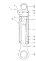
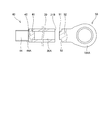
- FIG. 1 is a partial cross-sectional view showing a configuration of a hydraulic cylinder.
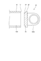
- Drawing 2 is a sectional view for explaining the manufacturing method of the cylinder tube concerning the embodiment of the present invention, and is a figure showing the state before joining.
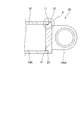
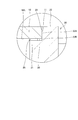
- Drawing 3 is a sectional view for explaining the manufacturing method of the cylinder tube concerning the embodiment of the present invention, and is a figure showing the 1st joining process.
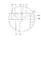
- FIG. 4 is an enlarged view of part A in FIG.
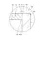
- Drawing 5 is a sectional view for explaining the manufacturing method of the cylinder tube concerning the embodiment of the present invention, and is a figure showing the 1st joining process.
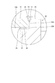
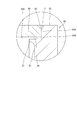
- Drawing 6 is a sectional view for explaining the manufacturing method of the cylinder tube concerning the embodiment of the present invention, and is a figure showing the 2nd joining process.
- FIG. 1 is a partial cross-sectional view showing a configuration of a hydraulic cylinder.
- Drawing 2 is a sectional view for explaining the manufacturing method of the cylinder tube concerning the embodiment of the present invention, and
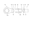
- FIG. 7 is a cross-sectional view for explaining the manufacturing method of the piston rod according to the embodiment of the present invention, and shows a state before joining.
- FIG. 8 is a cross-sectional view for explaining the manufacturing method of the piston rod according to the embodiment of the present invention, and shows a state in which the joining of the first member and the second member is completed.
- FIG. 9 is a cross-sectional view for explaining the manufacturing method of the piston rod according to the embodiment of the present invention, and shows a state before the rod body and the rod head are joined.
- FIG. 10 is a cross-sectional view for explaining a modification of the method for manufacturing a cylinder tube according to the embodiment of the present invention.
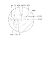
- FIG. 11 is a cross-sectional view for explaining a comparative example of a method for manufacturing a cylinder tube according to an embodiment of the present invention.
- the hydraulic cylinder 1 is an actuator that expands and contracts by the hydraulic pressure of the hydraulic oil (working fluid) in the rod side chamber 3 and the anti-rod side chamber 4 which are two cylinder chambers.
- the hydraulic cylinder 1 includes a cylindrical cylinder tube 100, a piston rod 101 inserted into the cylinder tube 100, and an inner peripheral surface of the cylinder tube 100 provided at an end of the piston rod 101. And a piston 2 that slides along.
- the cylinder tube 100 is provided with a cylindrical cylinder head 5 that seals an opening at one end (tip) and slidably supports the piston rod 101.
- the cylinder head 5 is fastened to the cylinder tube 100 via a plurality of fastening bolts (not shown) arranged in the circumferential direction.
- attachment portions (clevises) 100 ⁇ / b> A and 101 ⁇ / b> A for attaching the hydraulic cylinder 1 to other devices are provided at the proximal end portion of the cylinder tube 100 and the distal end portion of the piston rod 101, respectively.
- the piston 2 is attached to the proximal end portion of the piston rod 101 by screw fastening.
- the inside of the cylinder tube 100 is partitioned by the piston 2 into a rod side chamber 3 and an anti-rod side chamber 4.
- the rod side chamber 3 and the anti-rod side chamber 4 are filled with working oil as a working fluid.
- the hydraulic oil is supplied to the anti-rod side chamber 4 through a port (not shown) provided in the cylinder tube 100 and discharged from the rod side chamber 3 chamber, so that the piston rod 101 moves in the extending direction.
- the hydraulic oil is supplied to the rod side chamber 3 and discharged from the non-rod side chamber 4, whereby the piston rod 101 moves in the contracting direction.
- the hydraulic pressure of the hydraulic oil acts on the cylinder tube 100 as an internal pressure.
- the cylinder tube 100 is manufactured by joining a tube main body 10 as a first member and a head member 20 as a second member by friction welding (joining process).
- the tube body 10 is formed in a cylindrical shape having through holes 10A that are open on both end faces in the axial direction. Both end surfaces of the tube body 10 are formed as annular planes.
- the through hole 10 ⁇ / b> A corresponds to a hollow portion formed in the end surface 11 of the tube body 10 joined to the head member 20.
- the head member 20 includes a protruding portion 21 formed so as to be fitted into the through hole 10A of the tube main body 10 and a flange portion 22 provided from the protruding portion 21 toward the radially outer side.
- the flange portion 22 is provided with a mounting portion 100A on the opposite side of the protruding portion 21 in the axial direction.
- the flange portion 22 has an annular surface 23 that has the same outer diameter as the outer diameter of the tube body 10 and is formed as an annular flat surface.
- the protruding portion 21 is provided coaxially with the flange portion 22 and is formed in a cylindrical shape protruding from the annular surface 23.
- the flange 22 side is referred to as the “root” of the protrusion 21, and the opposite side of the root is referred to as the “tip” of the protrusion 21.
- the cylinder tube 100 is manufactured by the following manufacturing process.
- the following step (2) corresponds to the first bonding step
- step (4) corresponds to the second bonding step.
- the broken line in FIG. 6 shows the bonding interface between the tube body 10 and the head member 20.
- the tube body 10 is moved toward the head member 20 in a state where the head member 20 is rotated around the axis. Then, the protruding portion 21 of the head member 20 is fitted into the through hole 10 ⁇ / b> A of the tube main body 10, and the end surface 11 of the tube main body 10 is pressed against the annular surface 23 of the head member 20. By pressing the end surface 11 of the tube body 10 against the annular surface 23, frictional heat is generated between the end surface 11 and the annular surface 23.
- the protrusion 21 is fitted into the through hole 10 ⁇ / b> A with a clearance 25. Therefore, the end surface 11 of the tube main body 10 abuts on a part on the outer peripheral side of the annular surface 23, and a part on the inner peripheral side of the annular surface 23 does not abut on the tube main body 10.
- the portion that contacts the end surface 11 of the tube body 10 is “contact portion 22 ⁇ / b> A” and is radially inward of the contact portion 22 ⁇ / b> A and does not contact the end surface 11.
- the region is referred to as “non-contact portion 22B”.
- the non-contact portion 22B is a portion that faces the clearance 25 between the through hole 10A of the tube body 10 and the protruding portion 21 of the head member 20, and is a portion that connects the contacting portion 22A and the protruding portion 21. .
- the end surface 11 and the contact portion 22A are softened. Moreover, the non-contact part 22B which does not contact
- the tube body 10 is further pressed against the head member 20 side with a large load, and the heated high temperature portion is plastically flowed to the outer peripheral side and the inner peripheral side as shown in FIG.
- the material plastically flowed to the outer peripheral side is discharged as a burr 15.
- the material plastically flowed to the inner peripheral side (hereinafter referred to as “inner peripheral side material 26”) is guided to a clearance 25 between the inner peripheral surface of the tube body 10 and the outer peripheral surface of the protruding portion 21, and this clearance. 25 is filled.
- the burr 15 discharged to the outer peripheral side of the joint surface between the tube main body 10 and the head member 20 is cut out after the completion of the joint, and the outer periphery between the tube main body 10 and the head member 20 is processed into a smoothly continuous state. If the presence of the burr 15 is not a problem, the burr 15 may remain on the outer peripheral side of the cylinder tube 100 without cutting the burr 15.
- burrs are also generated on the inner peripheral side of the cylinder tube 100.
- oxide scale is generated.
- the burr and oxide scale on the inner peripheral side of the cylinder tube 100 are difficult to remove and clean. If hydraulic fluid is introduced into the cylinder tube 100 in a state where such an inner peripheral burr is generated, the oxidized scale may be mixed into the hydraulic fluid and become so-called contamination.
- the inner circumferential side material 26 it is desirable to control the plastic flow of the inner circumferential side material 26 so as to fill the clearance 25 while not flowing into the inner space of the cylinder tube 100. Specifically, it is desirable that the inner circumferential side material 26 is filled with the clearance 25 to the extent that it protrudes from the end face of the protruding portion 21 to the left side in FIG. Thereby, generation
- a quality inspection is performed on the friction welding portion between the tube body 10 and the head member 20 by a nondestructive test such as ultrasonic flaw detection.
- a nondestructive test such as ultrasonic flaw detection.
- the head member 120 does not have the protruding portion 21, and the end surface 122A is formed as a circular plane.
- the end surface 11 of the tube main body 10 and the end surface 122 of the head member 120 are brought into contact with each other and subjected to friction welding. At this time, the material softened by the frictional heat is discharged as a burr 126 on the inner peripheral side.
- the through hole 10A is There is a risk of recognizing it as a defect due to poor bonding. For this reason, in the cylinder tube 200 manufactured by the manufacturing method according to the comparative example, it is difficult to perform quality inspection by a nondestructive test.
- the non-contact portion 22B is also joined to the tube body 10 by heating and softening the non-contact portion 22B.
- the size of the clearance 25 is set so that it can be heated until the non-contact portion 22B is softened by frictional heat between the end surface 11 of the tube body 10 and the contact portion 22A of the head member 20.
- the cylinder tube 100 is formed in which the joining interface between the head member 20 and the tube main body 10 extends from the root portion of the protruding portion 21 of the head member 20 to the flange portion 22 and the outer peripheral surface of the tube main body 10.
- the clearance 25 before joining does not remain, and the joined portion between the tube body 10 and the head member 20 has a solid structure. For this reason, it is prevented that the clearance 25 before joining is recognized as a defect in the nondestructive test, and the quality inspection by the nondestructive test can be easily performed.
- burrs generated on the inner peripheral side of the cylinder tube 100 can be suppressed. Therefore, it can suppress that an oxide scale mixes with hydraulic fluid and becomes a contamination.
- the clearance 25 should just fill the part from the front end side (base side of the protrusion part 21) of the tube main body 10 which is the right side in FIG. 26 is not required to be filled. It is sufficient that at least a part of the clearance 25 inside the joint portion between the tube main body 10 and the head member 20 is filled and the joint portion between the tube main body 10 and the head member 20 has a solid structure. That is, in this specification, “the clearance 25 is filled” does not mean that the entire clearance 25 is filled, but the clearance is formed on the distal end side (left side in FIG. 6) of the protruding portion 21. This includes the case where 25 remains as a gap.
- the piston rod 101 is manufactured by joining a rod main body 30 as a first member, a screw member 40 and a rod head 50 as second members by friction welding.
- the rod body 30 is formed in a cylindrical shape having through holes 30A that are open on both end faces in the axial direction. Both end surfaces 31A and 31B of the rod body 30 are formed as annular planes.
- the through hole 30 ⁇ / b> A corresponds to a hollow portion formed in each of the end surfaces 31 ⁇ / b> A and 31 ⁇ / b> B of the rod body 30 joined to the screw member 40 and the rod head 50.
- the screw member 40 includes a protruding portion 41 formed so as to be fitted into the through hole 30A of the rod main body 30, and a flange portion 42 provided from the protruding portion 41 toward the radially outer side.
- a boss portion 44 is provided on the flange portion 42 on the opposite side of the protruding portion 41 in the axial direction.
- the boss portion 44 is formed with a male screw 44A on the outer periphery, and the piston 2 is screwed.
- the flange portion 42 has an annular surface 43 that has the same outer diameter as that of the rod body 30 and is formed as an annular flat surface.
- the protruding portion 41 is provided coaxially with the flange portion 42 and is formed in a columnar shape protruding from the annular surface 43.
- the rod head 50 has a protruding portion 51 formed so as to be fitted into the through hole 30A of the rod main body 30, and a flange portion 52 provided from the protruding portion 51 toward the radially outer side.
- the flange portion 52 is provided with a mounting portion 101A on the opposite side of the protruding portion 51 in the axial direction.
- the flange portion 52 has an annular surface 53 that has the same outer diameter as that of the rod body 30 and is formed as an annular flat surface.
- the protruding portion 51 is provided coaxially with the flange portion 52 and is formed in a cylindrical shape protruding from the annular surface 53.
- the piston rod 101 is manufactured by joining such a rod body 30, the screw member 40, and the rod head 50 by the above joining method similar to the joining of the tube body 10 and the head member 20.
- the hollow rod body 30 and the screw member 40 are first joined. Specifically, similarly to the above-described method of joining the tube body 10 and the head member 20, one end surface 31A of the rod body 30 and the annular surface 43 of the screw member 40 are arranged coaxially so as to face each other. The member 40 is moved toward the rod body 30 while being rotated about the axis. At this time, as shown in FIG. 7, the male screw 44 ⁇ / b> A is not formed on the boss portion 44 of the screw member 40.
- the protruding portion 41 of the screw member 40 is fitted into the through hole 30A of the rod main body 30, and one end surface 31A of the rod main body 30 is pressed against the annular surface 43 of the screw member 40 to generate frictional heat therebetween. generate.
- the contact portion 42A and the non-contact portion 42B of the flange portion 42 of the screw member 40 are heated and sufficiently softened, the rotation of the screw member 40 is stopped, and the rod body 30 is further loaded with a large load. Press against the screw member 40. Thereafter, the pressed state is held for a predetermined time, and both are joined (see FIG. 8).
- both the contact portion 42A that contacts the end surface 31A of the rod body 30 and the non-contact portion 42B that faces the clearance 45 are joined to the rod body 30.
- a piston rod 101 is formed in which the joint interface between the rod body 30 and the screw member 40 extends from the root portion of the protruding portion 41 of the screw member 40 to the flange portion 42 and the outer peripheral surface of the rod body 30. Note that, unlike the cylinder tube 100, the piston rod 101 does not lead hydraulic oil to the inside. Therefore, since it is not necessary to consider the occurrence of contamination, the inner peripheral side material 26 may flow out into the through-hole 30A to generate burrs on the inner peripheral side.
- a male screw 44A is formed on the outer periphery of the boss portion 44 (see FIG. 9).
- a male screw 44A may be formed in advance in the boss portion 44, and the screw member 40 on which the male screw 44A is formed and the rod body 30 may be joined by friction welding.
- the rod body 30 and the rod head 50 joined to the screw member 40 are joined (see FIG. 9). Since the joining of the rod body 30 and the rod head 50 is the same method as the joining of the tube body 10 and the head member 20 or the joining of the rod body 30 and the screw member 40, a specific description is omitted. In FIG. 8, reference numerals in parentheses indicate each configuration when the rod body 30 and the rod head 50 are joined.
- the piston rod 101 as shown in FIG. 1 is manufactured.
- the rod body 30 and the rod head 50 may be joined first, and then the rod body 30 and the screw member 40 may be joined to manufacture the piston rod 101.
- the joint portion has a solid structure, and the portion where the through hole 30A remains can be a hollow structure. Therefore, the inspection by the nondestructive test can be easily performed, and the weight of the piston rod 101 can be reduced. Moreover, since a part of piston rod 101 can be made into a hollow structure, a material yield can be improved and cost can be reduced.
- the protrusions 21 and 41 of the head member 20 and the rod head 50 have a solid structure.
- the hole 27 may be formed from the end surfaces of the projecting portions 21 and 41 within a range that does not overlap the inside of the joined portion, such as the joined portion of the tube main body and the head member shown in FIG.
- the protrusions 21 and 41 need only have a solid structure at the root portion connected to the flange portions 22 and 42 and joined to the tube main body 10 and the rod main body 30.
- the first member in the second member (head member 20, screw member 40, rod head 50), the first member (tube body 10, In addition to the contact portions 22A and 42A that contact the rod main body 30), the non-contact portions 22B and 42B are heated and softened so that the non-contact portions 22B and 42B also become the first member (the tube main body 10 and the rod main body). 30). Therefore, the clearances 25 and 45 before joining do not remain, and the joining portion between the first member (tube body 10, rod body 30) and the second member (head member 20, screw member 40, rod head 50) is It becomes a solid structure. For this reason, it is prevented that the clearances 25, 45, and 55 before joining are recognized as defects in the nondestructive test, and quality inspection by the nondestructive test can be easily performed.
- the inner circumferential side material 26 fills the clearance 25 between the through hole 10A of the tube main body 10 and the protruding portion 21 of the head member 20, while the cylinder tube It is controlled so as not to flow into the space inside 100.
- the 1st member (tube main body 10, rod main body 30) which has the hollow part (through-hole 10A, 30A) formed in end surface 11, 31A, 31B, and the protrusion part fitted to a hollow part (through-hole 10A, 30A) 21, 41, 51 and second members (head member 20, screw member 40, rod head 50) having flange portions 22, 42, 52 provided radially outward from the protrusions 21, 41, 51, Is a manufacturing method for manufacturing a joined body (cylinder tube 100, piston rod 101), wherein the hollow portions (through holes 10A, 30A) and the projecting portions 21, 41, 51 have predetermined clearances 25, 45, Including the joining step of abutting the end surfaces 11, 31A, 31B and the flange portions 22, 42, 52 and joining them by friction welding in a state of being fitted with 55 Is the second member (head member 20, The non-contact portions 22B, 42B, 52B facing the clearances 25, 45, 55 are heated at the flange portions 22, 42, 52 of the screw member 40 and the rod
- the joining process is performed such that the end surface 11 of the tube body 10 and the annular surface 23 of the flange portion 22 of the head member 20 are in contact with each other.
- the first joining step of generating frictional heat between the end surface 11 and the annular surface 23 of the flange portion 22 by rotating the member 20 relative to each other.
- the clearance 25 between the protrusion 21 and the through hole 10 ⁇ / b> A is filled with the material 26) from the base side of the protrusion 21.
- the inner circumferential side material 26 fills the clearance 25 between the through hole 10A of the tube main body 10 and the protruding portion 21 of the head member 20 at the time of joining, so that the joining portion has a solid structure more reliably. be able to.
- the 1st member (tube main body 10, rod main body 30) which has the hollow part (through-hole 10A, 30A) formed in end surface 11, 31A, 31B, and the protrusion fitted to a hollow part (through-hole 10A).
- Flange portions 22 provided to the radially outer side from the portions 21, 41, 51 and the protruding portions 21, 41, 51 and joined to the end surfaces 11, 31A, 31B of the first member (tube body 10, rod body 30),
- a joined body (cylinder tube 100, piston rod 101) constituted by a second member (head member 20, screw member 40, rod head 50) having 42 and 52 is a first member (tube main body 10, rod).
- the bonding interface extends radially outward from the base of the protrusions 21, 41, 51, and the bonding portion has a solid structure, so that the hollow portions (through holes 10A, 30A) are not subjected to nondestructive testing. It is not recognized as a defect. Therefore, quality inspection of the joined body (cylinder tube 100, piston rod 101) can be easily performed.
Landscapes
- Engineering & Computer Science (AREA)
- Mechanical Engineering (AREA)
- Physics & Mathematics (AREA)
- Fluid Mechanics (AREA)
- General Engineering & Computer Science (AREA)
- Pressure Welding/Diffusion-Bonding (AREA)
- Actuator (AREA)
Priority Applications (5)
| Application Number | Priority Date | Filing Date | Title |
|---|---|---|---|
| KR1020197031444A KR102457670B1 (ko) | 2017-03-29 | 2018-03-14 | 접합체의 제조 방법 및 접합체 |
| CN201880018869.5A CN110430963B (zh) | 2017-03-29 | 2018-03-14 | 接合体的制造方法、接合体、缸筒和活塞杆 |
| EP18778102.6A EP3603870A4 (en) | 2017-03-29 | 2018-03-14 | METHOD OF MANUFACTURING A CONNECTED BODY AND CONNECTED BODY |
| RU2019129292A RU2019129292A (ru) | 2017-03-29 | 2018-03-14 | Способ изготовления соединенного корпуса и соединенный корпус |
| US16/493,154 US11534852B2 (en) | 2017-03-29 | 2018-03-14 | Manufacturing method of joined body and joined body |
Applications Claiming Priority (2)
| Application Number | Priority Date | Filing Date | Title |
|---|---|---|---|
| JP2017-064976 | 2017-03-29 | ||
| JP2017064976A JP6506791B2 (ja) | 2017-03-29 | 2017-03-29 | 接合体の製造方法及び接合体 |
Publications (1)
| Publication Number | Publication Date |
|---|---|
| WO2018180500A1 true WO2018180500A1 (ja) | 2018-10-04 |
Family
ID=63675359
Family Applications (1)
| Application Number | Title | Priority Date | Filing Date |
|---|---|---|---|
| PCT/JP2018/010037 Ceased WO2018180500A1 (ja) | 2017-03-29 | 2018-03-14 | 接合体の製造方法及び接合体 |
Country Status (7)
| Country | Link |
|---|---|
| US (1) | US11534852B2 (enExample) |
| EP (1) | EP3603870A4 (enExample) |
| JP (1) | JP6506791B2 (enExample) |
| KR (1) | KR102457670B1 (enExample) |
| CN (1) | CN110430963B (enExample) |
| RU (1) | RU2019129292A (enExample) |
| WO (1) | WO2018180500A1 (enExample) |
Cited By (1)
| Publication number | Priority date | Publication date | Assignee | Title |
|---|---|---|---|---|
| US20210346978A1 (en) * | 2018-09-27 | 2021-11-11 | Kyb-Ys Co., Ltd. | Manufacturing method of joined body |
Families Citing this family (5)
| Publication number | Priority date | Publication date | Assignee | Title |
|---|---|---|---|---|
| WO2021060603A1 (ko) * | 2019-09-25 | 2021-04-01 | (주)에스에이치팩 | 유압 실린더 로드 |
| US11597032B2 (en) * | 2020-03-17 | 2023-03-07 | Paul Po Cheng | Method and system for modifying metal objects |
| DE102021001107A1 (de) * | 2021-03-02 | 2022-09-08 | Bümach Engineering International B.V. | Arbeitszylinder und Verfahren zu dessen Herstellung |
| JP7223064B2 (ja) * | 2021-06-11 | 2023-02-15 | 株式会社三條機械製作所 | シャフトの製造方法 |
| JP7775348B2 (ja) * | 2024-01-30 | 2025-11-25 | 古河ユニック株式会社 | シール部材仮置き用治具、シール部材挿入用治具及び流体圧シリンダの製造方法 |
Citations (4)
| Publication number | Priority date | Publication date | Assignee | Title |
|---|---|---|---|---|
| JP2007229719A (ja) * | 2006-02-27 | 2007-09-13 | Hitachi Ltd | 管端封口方法 |
| JP2008012573A (ja) * | 2006-07-07 | 2008-01-24 | Denso Corp | 回転摩擦接合方法および回転摩擦接合装置 |
| JP2010200816A (ja) | 2009-02-27 | 2010-09-16 | Hatsuta Seisakusho Co Ltd | 消火器及び消火剤貯蔵容器 |
| JP2017064976A (ja) | 2015-09-29 | 2017-04-06 | 日本プラスト株式会社 | 装飾部材 |
Family Cites Families (19)
| Publication number | Priority date | Publication date | Assignee | Title |
|---|---|---|---|---|
| US3144710A (en) | 1961-05-01 | 1964-08-18 | American Mach & Foundry | Friction sealing |
| US3793704A (en) * | 1972-07-24 | 1974-02-26 | Blackstone Corp | Methods of assembling joints |
| SU844187A1 (ru) * | 1979-09-07 | 1981-07-07 | Конструкторско-Технологический Ин-Ститут Автоматизации И Механи-Зации Автомобилестроения | Способ сварки труб давлением |
| JPS57156872A (en) * | 1981-03-24 | 1982-09-28 | Toyota Motor Corp | Soldering method of metallic pipe or ground bar and the like |
| FR2544806A1 (fr) * | 1983-04-20 | 1984-10-26 | Studer Norbert | Procede d'assemblage de deux pieces de revolution coaxiales, de meme diametre |
| US4832769A (en) * | 1987-05-19 | 1989-05-23 | A. R. D. Industries Ltd. | Friction welding flash trap seal and method of producing same |
| US4944977A (en) * | 1987-05-19 | 1990-07-31 | A.R.D. Industries Ltd. | Friction welding flash trap seal |
| US5211100A (en) | 1991-12-18 | 1993-05-18 | Clark Equipment Company | Inertial welded cylinder and method of making same |
| AU2003263463A1 (en) * | 2002-10-08 | 2004-05-04 | Scaglia Spa | Method to make mechanical components for fluid-dynamic devices, compressors or motors operating at high pressure, and mechanical components thus achieved |
| JP2005042578A (ja) * | 2003-07-25 | 2005-02-17 | Zexel Valeo Climate Control Corp | ピストンの尾部構成部品、ピストン及びピストンの製造方法 |
| RU2366552C2 (ru) * | 2006-05-29 | 2009-09-10 | Открытое акционерное общество "Специальное конструкторское бюро по геологоразведочной технике "(ОАО СКБ "Геотехника") | Соединение трубчатых деталей сваркой трением и способ сварки трением соединения трубчатых деталей |
| KR101061617B1 (ko) | 2006-08-30 | 2011-09-01 | 플루오르 테크놀로지스 코포레이션 | 이질적 물질을 용접하기 위한 방법 및 조성물 |
| DE102007021891A1 (de) * | 2007-05-10 | 2008-11-13 | Ejot Gmbh & Co. Kg | Verfahren zur Herstellung einer Reibschweißverbindung und Gestaltung der Reibschweißverbindung |
| US8286852B2 (en) * | 2008-02-29 | 2012-10-16 | Gesenkschmiede Schneider Gmbh | Method of friction welding of a piston having a cooling duct |
| JP5718003B2 (ja) | 2010-09-08 | 2015-05-13 | Ntn株式会社 | 等速自在継手の外側継手部材およびその摩擦圧接方法 |
| JP2014155991A (ja) * | 2013-02-15 | 2014-08-28 | Nikkeikin Aluminium Core Technology Co Ltd | 二部材の接合構造、二部材の接合方法およびこれを利用した自動車のステアリングシャフトのシャフト部と継手部を構成するヨーク間の接合構造 |
| WO2015096675A1 (zh) * | 2013-12-23 | 2015-07-02 | 上海交通大学 | 摩擦焊接结构组件、水冷内燃机的缸盖、水冷内燃机以及装有水冷内燃机的机械装置 |
| CN107427956A (zh) * | 2015-04-15 | 2017-12-01 | 株式会社小松制作所 | 金属部件的制造方法 |
| JP6611544B2 (ja) * | 2015-10-05 | 2019-11-27 | Kyb−Ys株式会社 | 接合体、流体圧シリンダ、及び接合体の製造方法 |
-
2017
- 2017-03-29 JP JP2017064976A patent/JP6506791B2/ja active Active
-
2018
- 2018-03-14 RU RU2019129292A patent/RU2019129292A/ru not_active Application Discontinuation
- 2018-03-14 EP EP18778102.6A patent/EP3603870A4/en not_active Withdrawn
- 2018-03-14 KR KR1020197031444A patent/KR102457670B1/ko active Active
- 2018-03-14 US US16/493,154 patent/US11534852B2/en active Active
- 2018-03-14 CN CN201880018869.5A patent/CN110430963B/zh active Active
- 2018-03-14 WO PCT/JP2018/010037 patent/WO2018180500A1/ja not_active Ceased
Patent Citations (4)
| Publication number | Priority date | Publication date | Assignee | Title |
|---|---|---|---|---|
| JP2007229719A (ja) * | 2006-02-27 | 2007-09-13 | Hitachi Ltd | 管端封口方法 |
| JP2008012573A (ja) * | 2006-07-07 | 2008-01-24 | Denso Corp | 回転摩擦接合方法および回転摩擦接合装置 |
| JP2010200816A (ja) | 2009-02-27 | 2010-09-16 | Hatsuta Seisakusho Co Ltd | 消火器及び消火剤貯蔵容器 |
| JP2017064976A (ja) | 2015-09-29 | 2017-04-06 | 日本プラスト株式会社 | 装飾部材 |
Non-Patent Citations (1)
| Title |
|---|
| See also references of EP3603870A4 |
Cited By (2)
| Publication number | Priority date | Publication date | Assignee | Title |
|---|---|---|---|---|
| US20210346978A1 (en) * | 2018-09-27 | 2021-11-11 | Kyb-Ys Co., Ltd. | Manufacturing method of joined body |
| US11958125B2 (en) * | 2018-09-27 | 2024-04-16 | Kyb Corporation | Manufacturing method of joined body |
Also Published As
| Publication number | Publication date |
|---|---|
| JP6506791B2 (ja) | 2019-04-24 |
| JP2018167276A (ja) | 2018-11-01 |
| CN110430963A (zh) | 2019-11-08 |
| CN110430963B (zh) | 2021-11-30 |
| KR102457670B1 (ko) | 2022-10-20 |
| US11534852B2 (en) | 2022-12-27 |
| EP3603870A1 (en) | 2020-02-05 |
| US20200114464A1 (en) | 2020-04-16 |
| KR20190133721A (ko) | 2019-12-03 |
| EP3603870A4 (en) | 2021-01-27 |
| RU2019129292A (ru) | 2021-04-29 |
Similar Documents
| Publication | Publication Date | Title |
|---|---|---|
| WO2018180500A1 (ja) | 接合体の製造方法及び接合体 | |
| KR102469617B1 (ko) | 접합체의 제조 방법 | |
| US10060482B2 (en) | Joint-site design comprising a hub and a shaft or a gear being friction welded | |
| US10272520B2 (en) | Joint-site structure for components to be connected by means of overlap friction welding, and method for connecting components by means of friction welding | |
| WO2017061276A1 (ja) | 接合体、流体圧シリンダ、及び接合体の製造方法 | |
| CN103038017B (zh) | 通过焊接电流和压入对轴和轮毂进行连接的方法以及轴和轮毂通过这种连接构成的装置 | |
| CN105849440A (zh) | 液力耦合器的制造方法以及液力耦合器 | |
| JP2018167276A5 (enExample) | ||
| JP2017508102A (ja) | 特に燃料圧送システムのためのユニット及びその製造方法 | |
| JP2018501111A (ja) | 流体導管要素及び流体導管要素を製造するための方法 | |
| WO2015029762A1 (ja) | ピストンロッドの製造方法 | |
| WO2012077405A1 (ja) | 中空エンジンバルブの溶接方法 | |
| JP7054374B2 (ja) | 接合体の製造方法 | |
| JP7054375B2 (ja) | 接合体の製造方法 | |
| JP2009262164A (ja) | 金属部材の接合方法 | |
| US11441688B2 (en) | Component of hydraulics, arrangement having a portion of the component, and method for joining together the component | |
| JP6644404B2 (ja) | 溶接構造および溶接方法 | |
| WO2019093274A1 (ja) | 耐圧機器、流体圧シリンダ、及び耐圧機器の製造方法 | |
| WO2019003394A1 (ja) | 樹脂製チューブ部材、樹脂製チューブ部材の製造方法、樹脂製管継手及び、樹脂製配管 | |
| JP2019027464A (ja) | 継手及び継手の製造方法 | |
| JP2025116896A (ja) | 流体圧シリンダ、流体圧シリンダの製造方法 | |
| JP2016068127A (ja) | 接合方法及び接合体 | |
| CN120062018A (zh) | 具有增强密封的燃料导轨 |
Legal Events
| Date | Code | Title | Description |
|---|---|---|---|
| 121 | Ep: the epo has been informed by wipo that ep was designated in this application |
Ref document number: 18778102 Country of ref document: EP Kind code of ref document: A1 |
|
| NENP | Non-entry into the national phase |
Ref country code: DE |
|
| ENP | Entry into the national phase |
Ref document number: 20197031444 Country of ref document: KR Kind code of ref document: A |
|
| WWE | Wipo information: entry into national phase |
Ref document number: 2019129292 Country of ref document: RU |
|
| ENP | Entry into the national phase |
Ref document number: 2018778102 Country of ref document: EP Effective date: 20191029 |