WO2018163411A1 - 複合材料部材、複合材料部材の製造方法及びその成形用型 - Google Patents
複合材料部材、複合材料部材の製造方法及びその成形用型 Download PDFInfo
- Publication number
- WO2018163411A1 WO2018163411A1 PCT/JP2017/009740 JP2017009740W WO2018163411A1 WO 2018163411 A1 WO2018163411 A1 WO 2018163411A1 JP 2017009740 W JP2017009740 W JP 2017009740W WO 2018163411 A1 WO2018163411 A1 WO 2018163411A1
- Authority
- WO
- WIPO (PCT)
- Prior art keywords
- resin
- layer
- frp
- composite material
- molding
- Prior art date
Links
- 239000002131 composite material Substances 0.000 title claims abstract description 47
- 238000000465 moulding Methods 0.000 title claims description 47
- 238000004519 manufacturing process Methods 0.000 title claims description 34
- 229920005989 resin Polymers 0.000 claims abstract description 165
- 239000011347 resin Substances 0.000 claims abstract description 165
- 239000000835 fiber Substances 0.000 claims abstract description 42
- 239000012783 reinforcing fiber Substances 0.000 claims description 95
- 238000000034 method Methods 0.000 claims description 27
- 239000000853 adhesive Substances 0.000 claims description 26
- 230000001070 adhesive effect Effects 0.000 claims description 26
- 239000000463 material Substances 0.000 claims description 21
- 238000005553 drilling Methods 0.000 claims description 11
- 239000012778 molding material Substances 0.000 claims description 9
- 229920002430 Fibre-reinforced plastic Polymers 0.000 claims description 6
- 239000011151 fibre-reinforced plastic Substances 0.000 claims description 6
- 238000002347 injection Methods 0.000 claims description 6
- 239000007924 injection Substances 0.000 claims description 6
- 239000000758 substrate Substances 0.000 claims 1
- 239000010410 layer Substances 0.000 description 157
- 230000002093 peripheral effect Effects 0.000 description 16
- 238000010586 diagram Methods 0.000 description 11
- 238000012986 modification Methods 0.000 description 10
- 230000004048 modification Effects 0.000 description 10
- 230000000694 effects Effects 0.000 description 7
- 239000011159 matrix material Substances 0.000 description 7
- 239000007788 liquid Substances 0.000 description 4
- 230000007547 defect Effects 0.000 description 3
- 229920000049 Carbon (fiber) Polymers 0.000 description 2
- 239000004734 Polyphenylene sulfide Substances 0.000 description 2
- 239000000654 additive Substances 0.000 description 2
- 239000004917 carbon fiber Substances 0.000 description 2
- 238000005520 cutting process Methods 0.000 description 2
- 239000003822 epoxy resin Substances 0.000 description 2
- VNWKTOKETHGBQD-UHFFFAOYSA-N methane Chemical compound C VNWKTOKETHGBQD-UHFFFAOYSA-N 0.000 description 2
- 229920002239 polyacrylonitrile Polymers 0.000 description 2
- 229920000647 polyepoxide Polymers 0.000 description 2
- 229920000069 polyphenylene sulfide Polymers 0.000 description 2
- 238000000926 separation method Methods 0.000 description 2
- HBMJWWWQQXIZIP-UHFFFAOYSA-N silicon carbide Chemical compound [Si+]#[C-] HBMJWWWQQXIZIP-UHFFFAOYSA-N 0.000 description 2
- 229910010271 silicon carbide Inorganic materials 0.000 description 2
- 229920005992 thermoplastic resin Polymers 0.000 description 2
- 229920001187 thermosetting polymer Polymers 0.000 description 2
- XLYOFNOQVPJJNP-UHFFFAOYSA-N water Substances O XLYOFNOQVPJJNP-UHFFFAOYSA-N 0.000 description 2
- ZOXJGFHDIHLPTG-UHFFFAOYSA-N Boron Chemical compound [B] ZOXJGFHDIHLPTG-UHFFFAOYSA-N 0.000 description 1
- OKTJSMMVPCPJKN-UHFFFAOYSA-N Carbon Chemical compound [C] OKTJSMMVPCPJKN-UHFFFAOYSA-N 0.000 description 1
- 239000004593 Epoxy Substances 0.000 description 1
- JOYRKODLDBILNP-UHFFFAOYSA-N Ethyl urethane Chemical compound CCOC(N)=O JOYRKODLDBILNP-UHFFFAOYSA-N 0.000 description 1
- PNEYBMLMFCGWSK-UHFFFAOYSA-N aluminium oxide Inorganic materials [O-2].[O-2].[O-2].[Al+3].[Al+3] PNEYBMLMFCGWSK-UHFFFAOYSA-N 0.000 description 1
- 238000013459 approach Methods 0.000 description 1
- 229920003235 aromatic polyamide Polymers 0.000 description 1
- 238000011074 autoclave method Methods 0.000 description 1
- 229910052796 boron Inorganic materials 0.000 description 1
- 239000002134 carbon nanofiber Substances 0.000 description 1
- 239000001913 cellulose Substances 0.000 description 1
- 229920002678 cellulose Polymers 0.000 description 1
- 239000003795 chemical substances by application Substances 0.000 description 1
- 239000003086 colorant Substances 0.000 description 1
- 238000002485 combustion reaction Methods 0.000 description 1
- 239000000470 constituent Substances 0.000 description 1
- 239000011162 core material Substances 0.000 description 1
- 238000005336 cracking Methods 0.000 description 1
- 230000007423 decrease Effects 0.000 description 1
- 230000003247 decreasing effect Effects 0.000 description 1
- 239000004744 fabric Substances 0.000 description 1
- 239000000945 filler Substances 0.000 description 1
- 239000006260 foam Substances 0.000 description 1
- -1 for example Polymers 0.000 description 1
- 230000004927 fusion Effects 0.000 description 1
- 239000003365 glass fiber Substances 0.000 description 1
- 229910002804 graphite Inorganic materials 0.000 description 1
- 239000010439 graphite Substances 0.000 description 1
- LNEPOXFFQSENCJ-UHFFFAOYSA-N haloperidol Chemical compound C1CC(O)(C=2C=CC(Cl)=CC=2)CCN1CCCC(=O)C1=CC=C(F)C=C1 LNEPOXFFQSENCJ-UHFFFAOYSA-N 0.000 description 1
- 238000009787 hand lay-up Methods 0.000 description 1
- 239000002184 metal Substances 0.000 description 1
- 239000000203 mixture Substances 0.000 description 1
- 239000005011 phenolic resin Substances 0.000 description 1
- 229920006122 polyamide resin Polymers 0.000 description 1
- 229920005668 polycarbonate resin Polymers 0.000 description 1
- 239000004431 polycarbonate resin Substances 0.000 description 1
- 229920001721 polyimide Polymers 0.000 description 1
- 239000009719 polyimide resin Substances 0.000 description 1
- 238000010248 power generation Methods 0.000 description 1
- 238000003825 pressing Methods 0.000 description 1
- 230000002787 reinforcement Effects 0.000 description 1
- 238000007493 shaping process Methods 0.000 description 1
- 239000000126 substance Substances 0.000 description 1
- 239000002344 surface layer Substances 0.000 description 1
- 238000005979 thermal decomposition reaction Methods 0.000 description 1
- 229920006337 unsaturated polyester resin Polymers 0.000 description 1
- 229920001567 vinyl ester resin Polymers 0.000 description 1
- 239000002759 woven fabric Substances 0.000 description 1
Images


Classifications
-
- B—PERFORMING OPERATIONS; TRANSPORTING
- B29—WORKING OF PLASTICS; WORKING OF SUBSTANCES IN A PLASTIC STATE IN GENERAL
- B29C—SHAPING OR JOINING OF PLASTICS; SHAPING OF MATERIAL IN A PLASTIC STATE, NOT OTHERWISE PROVIDED FOR; AFTER-TREATMENT OF THE SHAPED PRODUCTS, e.g. REPAIRING
- B29C45/00—Injection moulding, i.e. forcing the required volume of moulding material through a nozzle into a closed mould; Apparatus therefor
- B29C45/14—Injection moulding, i.e. forcing the required volume of moulding material through a nozzle into a closed mould; Apparatus therefor incorporating preformed parts or layers, e.g. injection moulding around inserts or for coating articles
- B29C45/14778—Injection moulding, i.e. forcing the required volume of moulding material through a nozzle into a closed mould; Apparatus therefor incorporating preformed parts or layers, e.g. injection moulding around inserts or for coating articles the article consisting of a material with particular properties, e.g. porous, brittle
- B29C45/14786—Fibrous material or fibre containing material, e.g. fibre mats or fibre reinforced material
-
- B—PERFORMING OPERATIONS; TRANSPORTING
- B32—LAYERED PRODUCTS
- B32B—LAYERED PRODUCTS, i.e. PRODUCTS BUILT-UP OF STRATA OF FLAT OR NON-FLAT, e.g. CELLULAR OR HONEYCOMB, FORM
- B32B5/00—Layered products characterised by the non- homogeneity or physical structure, i.e. comprising a fibrous, filamentary, particulate or foam layer; Layered products characterised by having a layer differing constitutionally or physically in different parts
- B32B5/02—Layered products characterised by the non- homogeneity or physical structure, i.e. comprising a fibrous, filamentary, particulate or foam layer; Layered products characterised by having a layer differing constitutionally or physically in different parts characterised by structural features of a fibrous or filamentary layer
- B32B5/12—Layered products characterised by the non- homogeneity or physical structure, i.e. comprising a fibrous, filamentary, particulate or foam layer; Layered products characterised by having a layer differing constitutionally or physically in different parts characterised by structural features of a fibrous or filamentary layer characterised by the relative arrangement of fibres or filaments of different layers, e.g. the fibres or filaments being parallel or perpendicular to each other
-
- B—PERFORMING OPERATIONS; TRANSPORTING
- B26—HAND CUTTING TOOLS; CUTTING; SEVERING
- B26F—PERFORATING; PUNCHING; CUTTING-OUT; STAMPING-OUT; SEVERING BY MEANS OTHER THAN CUTTING
- B26F1/00—Perforating; Punching; Cutting-out; Stamping-out; Apparatus therefor
- B26F1/02—Perforating by punching, e.g. with relatively-reciprocating punch and bed
- B26F1/12—Perforating by punching, e.g. with relatively-reciprocating punch and bed to notch margins of work
-
- B—PERFORMING OPERATIONS; TRANSPORTING
- B26—HAND CUTTING TOOLS; CUTTING; SEVERING
- B26F—PERFORATING; PUNCHING; CUTTING-OUT; STAMPING-OUT; SEVERING BY MEANS OTHER THAN CUTTING
- B26F1/00—Perforating; Punching; Cutting-out; Stamping-out; Apparatus therefor
- B26F1/26—Perforating by non-mechanical means, e.g. by fluid jet
-
- B—PERFORMING OPERATIONS; TRANSPORTING
- B29—WORKING OF PLASTICS; WORKING OF SUBSTANCES IN A PLASTIC STATE IN GENERAL
- B29C—SHAPING OR JOINING OF PLASTICS; SHAPING OF MATERIAL IN A PLASTIC STATE, NOT OTHERWISE PROVIDED FOR; AFTER-TREATMENT OF THE SHAPED PRODUCTS, e.g. REPAIRING
- B29C39/00—Shaping by casting, i.e. introducing the moulding material into a mould or between confining surfaces without significant moulding pressure; Apparatus therefor
- B29C39/02—Shaping by casting, i.e. introducing the moulding material into a mould or between confining surfaces without significant moulding pressure; Apparatus therefor for making articles of definite length, i.e. discrete articles
- B29C39/10—Shaping by casting, i.e. introducing the moulding material into a mould or between confining surfaces without significant moulding pressure; Apparatus therefor for making articles of definite length, i.e. discrete articles incorporating preformed parts or layers, e.g. casting around inserts or for coating articles
-
- B—PERFORMING OPERATIONS; TRANSPORTING
- B29—WORKING OF PLASTICS; WORKING OF SUBSTANCES IN A PLASTIC STATE IN GENERAL
- B29C—SHAPING OR JOINING OF PLASTICS; SHAPING OF MATERIAL IN A PLASTIC STATE, NOT OTHERWISE PROVIDED FOR; AFTER-TREATMENT OF THE SHAPED PRODUCTS, e.g. REPAIRING
- B29C43/00—Compression moulding, i.e. applying external pressure to flow the moulding material; Apparatus therefor
- B29C43/02—Compression moulding, i.e. applying external pressure to flow the moulding material; Apparatus therefor of articles of definite length, i.e. discrete articles
-
- B—PERFORMING OPERATIONS; TRANSPORTING
- B29—WORKING OF PLASTICS; WORKING OF SUBSTANCES IN A PLASTIC STATE IN GENERAL
- B29C—SHAPING OR JOINING OF PLASTICS; SHAPING OF MATERIAL IN A PLASTIC STATE, NOT OTHERWISE PROVIDED FOR; AFTER-TREATMENT OF THE SHAPED PRODUCTS, e.g. REPAIRING
- B29C45/00—Injection moulding, i.e. forcing the required volume of moulding material through a nozzle into a closed mould; Apparatus therefor
- B29C45/14—Injection moulding, i.e. forcing the required volume of moulding material through a nozzle into a closed mould; Apparatus therefor incorporating preformed parts or layers, e.g. injection moulding around inserts or for coating articles
- B29C45/14336—Coating a portion of the article, e.g. the edge of the article
-
- B—PERFORMING OPERATIONS; TRANSPORTING
- B29—WORKING OF PLASTICS; WORKING OF SUBSTANCES IN A PLASTIC STATE IN GENERAL
- B29C—SHAPING OR JOINING OF PLASTICS; SHAPING OF MATERIAL IN A PLASTIC STATE, NOT OTHERWISE PROVIDED FOR; AFTER-TREATMENT OF THE SHAPED PRODUCTS, e.g. REPAIRING
- B29C70/00—Shaping composites, i.e. plastics material comprising reinforcements, fillers or preformed parts, e.g. inserts
- B29C70/04—Shaping composites, i.e. plastics material comprising reinforcements, fillers or preformed parts, e.g. inserts comprising reinforcements only, e.g. self-reinforcing plastics
- B29C70/28—Shaping operations therefor
- B29C70/40—Shaping or impregnating by compression not applied
- B29C70/42—Shaping or impregnating by compression not applied for producing articles of definite length, i.e. discrete articles
- B29C70/46—Shaping or impregnating by compression not applied for producing articles of definite length, i.e. discrete articles using matched moulds, e.g. for deforming sheet moulding compounds [SMC] or prepregs
- B29C70/48—Shaping or impregnating by compression not applied for producing articles of definite length, i.e. discrete articles using matched moulds, e.g. for deforming sheet moulding compounds [SMC] or prepregs and impregnating the reinforcements in the closed mould, e.g. resin transfer moulding [RTM], e.g. by vacuum
-
- B—PERFORMING OPERATIONS; TRANSPORTING
- B29—WORKING OF PLASTICS; WORKING OF SUBSTANCES IN A PLASTIC STATE IN GENERAL
- B29C—SHAPING OR JOINING OF PLASTICS; SHAPING OF MATERIAL IN A PLASTIC STATE, NOT OTHERWISE PROVIDED FOR; AFTER-TREATMENT OF THE SHAPED PRODUCTS, e.g. REPAIRING
- B29C70/00—Shaping composites, i.e. plastics material comprising reinforcements, fillers or preformed parts, e.g. inserts
- B29C70/04—Shaping composites, i.e. plastics material comprising reinforcements, fillers or preformed parts, e.g. inserts comprising reinforcements only, e.g. self-reinforcing plastics
- B29C70/28—Shaping operations therefor
- B29C70/54—Component parts, details or accessories; Auxiliary operations, e.g. feeding or storage of prepregs or SMC after impregnation or during ageing
- B29C70/545—Perforating, cutting or machining during or after moulding
-
- B—PERFORMING OPERATIONS; TRANSPORTING
- B29—WORKING OF PLASTICS; WORKING OF SUBSTANCES IN A PLASTIC STATE IN GENERAL
- B29C—SHAPING OR JOINING OF PLASTICS; SHAPING OF MATERIAL IN A PLASTIC STATE, NOT OTHERWISE PROVIDED FOR; AFTER-TREATMENT OF THE SHAPED PRODUCTS, e.g. REPAIRING
- B29C70/00—Shaping composites, i.e. plastics material comprising reinforcements, fillers or preformed parts, e.g. inserts
- B29C70/68—Shaping composites, i.e. plastics material comprising reinforcements, fillers or preformed parts, e.g. inserts by incorporating or moulding on preformed parts, e.g. inserts or layers, e.g. foam blocks
- B29C70/74—Moulding material on a relatively small portion of the preformed part, e.g. outsert moulding
-
- B—PERFORMING OPERATIONS; TRANSPORTING
- B32—LAYERED PRODUCTS
- B32B—LAYERED PRODUCTS, i.e. PRODUCTS BUILT-UP OF STRATA OF FLAT OR NON-FLAT, e.g. CELLULAR OR HONEYCOMB, FORM
- B32B27/00—Layered products comprising a layer of synthetic resin
- B32B27/12—Layered products comprising a layer of synthetic resin next to a fibrous or filamentary layer
-
- B—PERFORMING OPERATIONS; TRANSPORTING
- B32—LAYERED PRODUCTS
- B32B—LAYERED PRODUCTS, i.e. PRODUCTS BUILT-UP OF STRATA OF FLAT OR NON-FLAT, e.g. CELLULAR OR HONEYCOMB, FORM
- B32B3/00—Layered products comprising a layer with external or internal discontinuities or unevennesses, or a layer of non-planar shape; Layered products comprising a layer having particular features of form
- B32B3/02—Layered products comprising a layer with external or internal discontinuities or unevennesses, or a layer of non-planar shape; Layered products comprising a layer having particular features of form characterised by features of form at particular places, e.g. in edge regions
- B32B3/06—Layered products comprising a layer with external or internal discontinuities or unevennesses, or a layer of non-planar shape; Layered products comprising a layer having particular features of form characterised by features of form at particular places, e.g. in edge regions for securing layers together; for attaching the product to another member, e.g. to a support, or to another product, e.g. groove/tongue, interlocking
-
- B—PERFORMING OPERATIONS; TRANSPORTING
- B32—LAYERED PRODUCTS
- B32B—LAYERED PRODUCTS, i.e. PRODUCTS BUILT-UP OF STRATA OF FLAT OR NON-FLAT, e.g. CELLULAR OR HONEYCOMB, FORM
- B32B3/00—Layered products comprising a layer with external or internal discontinuities or unevennesses, or a layer of non-planar shape; Layered products comprising a layer having particular features of form
- B32B3/02—Layered products comprising a layer with external or internal discontinuities or unevennesses, or a layer of non-planar shape; Layered products comprising a layer having particular features of form characterised by features of form at particular places, e.g. in edge regions
- B32B3/08—Layered products comprising a layer with external or internal discontinuities or unevennesses, or a layer of non-planar shape; Layered products comprising a layer having particular features of form characterised by features of form at particular places, e.g. in edge regions characterised by added members at particular parts
-
- B—PERFORMING OPERATIONS; TRANSPORTING
- B32—LAYERED PRODUCTS
- B32B—LAYERED PRODUCTS, i.e. PRODUCTS BUILT-UP OF STRATA OF FLAT OR NON-FLAT, e.g. CELLULAR OR HONEYCOMB, FORM
- B32B3/00—Layered products comprising a layer with external or internal discontinuities or unevennesses, or a layer of non-planar shape; Layered products comprising a layer having particular features of form
- B32B3/26—Layered products comprising a layer with external or internal discontinuities or unevennesses, or a layer of non-planar shape; Layered products comprising a layer having particular features of form characterised by a particular shape of the outline of the cross-section of a continuous layer; characterised by a layer with cavities or internal voids ; characterised by an apertured layer
- B32B3/266—Layered products comprising a layer with external or internal discontinuities or unevennesses, or a layer of non-planar shape; Layered products comprising a layer having particular features of form characterised by a particular shape of the outline of the cross-section of a continuous layer; characterised by a layer with cavities or internal voids ; characterised by an apertured layer characterised by an apertured layer, the apertures going through the whole thickness of the layer, e.g. expanded metal, perforated layer, slit layer regular cells B32B3/12
-
- B—PERFORMING OPERATIONS; TRANSPORTING
- B32—LAYERED PRODUCTS
- B32B—LAYERED PRODUCTS, i.e. PRODUCTS BUILT-UP OF STRATA OF FLAT OR NON-FLAT, e.g. CELLULAR OR HONEYCOMB, FORM
- B32B38/00—Ancillary operations in connection with laminating processes
- B32B38/04—Punching, slitting or perforating
-
- B—PERFORMING OPERATIONS; TRANSPORTING
- B32—LAYERED PRODUCTS
- B32B—LAYERED PRODUCTS, i.e. PRODUCTS BUILT-UP OF STRATA OF FLAT OR NON-FLAT, e.g. CELLULAR OR HONEYCOMB, FORM
- B32B5/00—Layered products characterised by the non- homogeneity or physical structure, i.e. comprising a fibrous, filamentary, particulate or foam layer; Layered products characterised by having a layer differing constitutionally or physically in different parts
- B32B5/02—Layered products characterised by the non- homogeneity or physical structure, i.e. comprising a fibrous, filamentary, particulate or foam layer; Layered products characterised by having a layer differing constitutionally or physically in different parts characterised by structural features of a fibrous or filamentary layer
- B32B5/024—Woven fabric
-
- B—PERFORMING OPERATIONS; TRANSPORTING
- B32—LAYERED PRODUCTS
- B32B—LAYERED PRODUCTS, i.e. PRODUCTS BUILT-UP OF STRATA OF FLAT OR NON-FLAT, e.g. CELLULAR OR HONEYCOMB, FORM
- B32B5/00—Layered products characterised by the non- homogeneity or physical structure, i.e. comprising a fibrous, filamentary, particulate or foam layer; Layered products characterised by having a layer differing constitutionally or physically in different parts
- B32B5/22—Layered products characterised by the non- homogeneity or physical structure, i.e. comprising a fibrous, filamentary, particulate or foam layer; Layered products characterised by having a layer differing constitutionally or physically in different parts characterised by the presence of two or more layers which are next to each other and are fibrous, filamentary, formed of particles or foamed
- B32B5/24—Layered products characterised by the non- homogeneity or physical structure, i.e. comprising a fibrous, filamentary, particulate or foam layer; Layered products characterised by having a layer differing constitutionally or physically in different parts characterised by the presence of two or more layers which are next to each other and are fibrous, filamentary, formed of particles or foamed one layer being a fibrous or filamentary layer
- B32B5/26—Layered products characterised by the non- homogeneity or physical structure, i.e. comprising a fibrous, filamentary, particulate or foam layer; Layered products characterised by having a layer differing constitutionally or physically in different parts characterised by the presence of two or more layers which are next to each other and are fibrous, filamentary, formed of particles or foamed one layer being a fibrous or filamentary layer another layer next to it also being fibrous or filamentary
-
- B—PERFORMING OPERATIONS; TRANSPORTING
- B32—LAYERED PRODUCTS
- B32B—LAYERED PRODUCTS, i.e. PRODUCTS BUILT-UP OF STRATA OF FLAT OR NON-FLAT, e.g. CELLULAR OR HONEYCOMB, FORM
- B32B7/00—Layered products characterised by the relation between layers; Layered products characterised by the relative orientation of features between layers, or by the relative values of a measurable parameter between layers, i.e. products comprising layers having different physical, chemical or physicochemical properties; Layered products characterised by the interconnection of layers
- B32B7/02—Physical, chemical or physicochemical properties
- B32B7/022—Mechanical properties
-
- B—PERFORMING OPERATIONS; TRANSPORTING
- B29—WORKING OF PLASTICS; WORKING OF SUBSTANCES IN A PLASTIC STATE IN GENERAL
- B29C—SHAPING OR JOINING OF PLASTICS; SHAPING OF MATERIAL IN A PLASTIC STATE, NOT OTHERWISE PROVIDED FOR; AFTER-TREATMENT OF THE SHAPED PRODUCTS, e.g. REPAIRING
- B29C45/00—Injection moulding, i.e. forcing the required volume of moulding material through a nozzle into a closed mould; Apparatus therefor
- B29C45/0053—Injection moulding, i.e. forcing the required volume of moulding material through a nozzle into a closed mould; Apparatus therefor combined with a final operation, e.g. shaping
- B29C45/0055—Shaping
- B29C2045/0058—Shaping removing material
-
- B—PERFORMING OPERATIONS; TRANSPORTING
- B32—LAYERED PRODUCTS
- B32B—LAYERED PRODUCTS, i.e. PRODUCTS BUILT-UP OF STRATA OF FLAT OR NON-FLAT, e.g. CELLULAR OR HONEYCOMB, FORM
- B32B2250/00—Layers arrangement
- B32B2250/20—All layers being fibrous or filamentary
-
- B—PERFORMING OPERATIONS; TRANSPORTING
- B32—LAYERED PRODUCTS
- B32B—LAYERED PRODUCTS, i.e. PRODUCTS BUILT-UP OF STRATA OF FLAT OR NON-FLAT, e.g. CELLULAR OR HONEYCOMB, FORM
- B32B2250/00—Layers arrangement
- B32B2250/40—Symmetrical or sandwich layers, e.g. ABA, ABCBA, ABCCBA
-
- B—PERFORMING OPERATIONS; TRANSPORTING
- B32—LAYERED PRODUCTS
- B32B—LAYERED PRODUCTS, i.e. PRODUCTS BUILT-UP OF STRATA OF FLAT OR NON-FLAT, e.g. CELLULAR OR HONEYCOMB, FORM
- B32B2250/00—Layers arrangement
- B32B2250/44—Number of layers variable across the laminate
-
- B—PERFORMING OPERATIONS; TRANSPORTING
- B32—LAYERED PRODUCTS
- B32B—LAYERED PRODUCTS, i.e. PRODUCTS BUILT-UP OF STRATA OF FLAT OR NON-FLAT, e.g. CELLULAR OR HONEYCOMB, FORM
- B32B2260/00—Layered product comprising an impregnated, embedded, or bonded layer wherein the layer comprises an impregnation, embedding, or binder material
- B32B2260/02—Composition of the impregnated, bonded or embedded layer
- B32B2260/021—Fibrous or filamentary layer
- B32B2260/023—Two or more layers
-
- B—PERFORMING OPERATIONS; TRANSPORTING
- B32—LAYERED PRODUCTS
- B32B—LAYERED PRODUCTS, i.e. PRODUCTS BUILT-UP OF STRATA OF FLAT OR NON-FLAT, e.g. CELLULAR OR HONEYCOMB, FORM
- B32B2260/00—Layered product comprising an impregnated, embedded, or bonded layer wherein the layer comprises an impregnation, embedding, or binder material
- B32B2260/04—Impregnation, embedding, or binder material
- B32B2260/046—Synthetic resin
-
- B—PERFORMING OPERATIONS; TRANSPORTING
- B32—LAYERED PRODUCTS
- B32B—LAYERED PRODUCTS, i.e. PRODUCTS BUILT-UP OF STRATA OF FLAT OR NON-FLAT, e.g. CELLULAR OR HONEYCOMB, FORM
- B32B2605/00—Vehicles
- B32B2605/08—Cars
-
- B—PERFORMING OPERATIONS; TRANSPORTING
- B32—LAYERED PRODUCTS
- B32B—LAYERED PRODUCTS, i.e. PRODUCTS BUILT-UP OF STRATA OF FLAT OR NON-FLAT, e.g. CELLULAR OR HONEYCOMB, FORM
- B32B5/00—Layered products characterised by the non- homogeneity or physical structure, i.e. comprising a fibrous, filamentary, particulate or foam layer; Layered products characterised by having a layer differing constitutionally or physically in different parts
- B32B5/14—Layered products characterised by the non- homogeneity or physical structure, i.e. comprising a fibrous, filamentary, particulate or foam layer; Layered products characterised by having a layer differing constitutionally or physically in different parts characterised by a layer differing constitutionally or physically in different parts, e.g. denser near its faces
- B32B5/145—Variation across the thickness of the layer
-
- Y—GENERAL TAGGING OF NEW TECHNOLOGICAL DEVELOPMENTS; GENERAL TAGGING OF CROSS-SECTIONAL TECHNOLOGIES SPANNING OVER SEVERAL SECTIONS OF THE IPC; TECHNICAL SUBJECTS COVERED BY FORMER USPC CROSS-REFERENCE ART COLLECTIONS [XRACs] AND DIGESTS
- Y10—TECHNICAL SUBJECTS COVERED BY FORMER USPC
- Y10T—TECHNICAL SUBJECTS COVERED BY FORMER US CLASSIFICATION
- Y10T428/00—Stock material or miscellaneous articles
- Y10T428/24—Structurally defined web or sheet [e.g., overall dimension, etc.]
- Y10T428/24273—Structurally defined web or sheet [e.g., overall dimension, etc.] including aperture
- Y10T428/24322—Composite web or sheet
Definitions
- the present invention relates to a composite material member, a method for manufacturing the composite material member, and a mold for molding the composite material member.
- An object of the present invention is to suppress the occurrence of detachment of reinforcing fibers and resin defects caused by drilling in a composite material member such as an FRP member.
- a resin-rich layer having a fiber content lower than that of the FRP layer is formed on at least a part of the surface of the FRP layer, and a hole is formed so as to penetrate the FRP layer and the resin-rich layer.
- FIG. 1A is a top view of the composite material member according to the first embodiment, showing a state before the collar and the washer are mounted.
- FIG. 1B is a cross-sectional view taken along line Ib-Ib of FIG. 1A.
- FIG. 2 is a cross-sectional view of the composite material member according to the first embodiment.
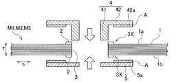
- FIG. 3A shows a state when a general FRP member is drilled with a drill.
- FIG. 3B shows a state when a general FRP member is drilled.
- FIG. 3C shows a state when a general FRP member is drilled.
- FIG. 3D shows a state when a general FRP member is drilled.
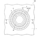
- FIG. 4A is a top view of the composite material member according to the second embodiment. The color and washer are omitted for simplicity.
- FIG. 4B is a cross-sectional view taken along line IVb-IVb in FIG. 4A.
- FIG. 5A is a top view of the composite material member according to the third embodiment. The color and washer are omitted for simplicity.
- FIG. 5B is a cross-sectional view taken along line Vb-Vb in FIG. 5A.
- FIG. 6A is a top view of the composite material member according to the fourth embodiment. The color and washer are omitted for simplicity. 6B is a cross-sectional view taken along line VIb-VIb of FIG. 6A.
- FIG. 7A is a diagram illustrating a method for manufacturing a composite material member.
- FIG. 7B is a diagram illustrating a method for manufacturing a composite material member.
- FIG. 7B is a diagram illustrating a method for manufacturing a composite material member.
- FIG. 7C is a diagram illustrating a method for manufacturing a composite material member.
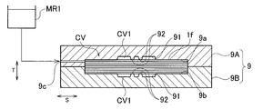
- FIG. 8A is an enlarged view of a main part of a mold for molding a composite material member.
- 8B is a cross-sectional view taken along line VIIIb-VIIIb in FIG. 8A.
- FIG. 9A is a diagram illustrating a method for manufacturing a composite material member.
- FIG. 9B is a diagram illustrating a method for manufacturing a composite material member.
- FIG. 9C is a diagram illustrating a method for manufacturing a composite material member.
- FIG. 10A is a diagram illustrating another method for manufacturing a composite material member.
- FIG. 10B is a diagram illustrating another method of manufacturing a composite material member.
- FIG. 10C is a diagram illustrating another method of manufacturing the composite material member.
- FIG. 11A is a diagram illustrating another method of manufacturing a composite material member.
- FIG. 11B is a diagram illustrating another method for manufacturing a composite material member.
- member CMs composite material members
- terms representing directions such as “up” and “down” are defined for convenience in order to describe the positional relationship between the respective parts, and do not limit the actual mounting posture or the like.
- the member CM according to the first embodiment includes an FRP layer 1, a resin rich layer 2 formed on an upper surface 1a of the FRP layer 1, and an FRP layer 1.
- the resin rich layer 2 formed on the lower surface 1b and the hole 3 formed in the thickness direction T of the member CM.
- the illustrated member CM is formed in a flat plate shape, but the shape can be appropriately selected according to the application, and may be, for example, a curved plate shape.
- the FRP layer 1 is made of fiber reinforced plastic, and is mainly composed of reinforced fibers F and matrix resin MR.
- the reinforcing fibers F are made of continuous fibers oriented along the surface direction S of the member CM.
- the reinforcing fibers F may have a laminated structure in which reinforcing fiber bundles are stacked in one direction or at different angles, or a woven fabric.
- the thickness of the FRP layer 1 is not particularly limited, and can be appropriately set according to the strength, rigidity, and the like required for the member CM.
- the reinforcing fiber F is not particularly limited, and for example, carbon fiber, glass fiber, polyaramid fiber, alumina fiber, silicon carbide fiber, boron fiber, silicon carbide fiber, or the like can be used.
- carbon fiber for example, polyacrylonitrile (PAN-based), pitch-based, cellulose-based, hydrocarbon-grown vapor-grown carbon fiber, graphite fiber, or the like can be used. Two or more of these fibers may be used in combination.
- the matrix resin MR is not particularly limited, and examples thereof include known thermosetting resins such as epoxy resins, phenol resins, unsaturated polyester resins, vinyl ester resins, polyimide resins, polycarbonate resins, polyamide resins, polyphenylene sulfide (PPS) resins, and the like.
- a thermoplastic resin can be used.
- the FRP layer 1 can contain various additives, such as a coloring agent and a filler, as components other than the reinforcing fiber F and the matrix resin MR.
- the resin rich layer 2 is mainly composed of the above-described known thermosetting resin or thermoplastic resin exemplified as the material of the matrix resin MR.
- the main component resin of the resin rich layer 2 may be the same resin as the matrix resin MR, a different resin, or a mixture thereof. Similar to the FRP layer 1, the resin-rich layer 2 can contain reinforcing fibers and various additives as components other than the main component resin.
- the resin rich layer 2 has a fiber content lower than that of the FRP layer 1.
- the fiber content of the FRP layer 1 is a volume ratio of the reinforcing fibers F included in the FRP layer 1 to the entire FRP layer 1, and the fiber content of the resin rich layer 2 is a resin of reinforcing fibers included in the resin rich layer 2. It is a volume ratio with respect to the entire rich layer 2.
- the holes 3 are formed so as to penetrate the FRP layer 1 and the resin rich layers 2 formed on the surfaces 1a and 1b on both sides thereof.
- a collar 4 is mounted in the hole 3.
- the collar 4 has a cylindrical portion 41 and a flange 42, and the cylindrical portion 41 is inserted through the hole 3.
- the flange 42 is bonded to the FRP layer 1 by an adhesive A provided in a gap G1 between the back surface 42a and the front surface 1a of the FRP layer 1.
- the upper resin-rich layer 2 is interposed between the front surface 1a of the FRP layer 1 and the rear surface 42a of the flange 42 with its surface in contact with the rear surface 42a of the flange 42, and defines the size of the gap G1. ing.
- a metal washer 5 is provided on the lower surface 1 b of the FRP layer 1.
- the washer 5 is bonded to the FRP layer 1 by an adhesive A provided in a gap G2 between the back surface 5a and the front surface 1b of the FRP layer 1.
- the lower resin-rich layer 2 is interposed between the front surface 1b of the FRP layer 1 and the back surface 5a of the washer 5 with its surface in contact with the back surface 5a of the washer 5, and defines the size of the gap G2. is doing.
- the adhesive A is not specifically limited, For example, well-known adhesives, such as an epoxy type and a urethane type, can be used.
- the peripheral part 3X of the hole 3 together with the collar 4 and the washer 5 constitute a fastening part FP of the member CM.
- the fastening portion FP is fastened to the article to be fastened 8 by a fastener (for example, a bolt 6 and a nut 7) inserted through the cylindrical portion 41 of the collar 4.
- a fastener for example, a bolt 6 and a nut 7
- the object to be fastened 8 is overlapped with the washer 5, the bolt 6 is inserted into the tubular portion 41 of the collar 4 and the hole 8 a of the fastened object 8, and the nut 7 is fastened to the bolt 6.
- the member CM and the fastened object 8 can be fastened.
- the washer 5 is omitted, and the upper surface 8b of the article 8 to be fastened is brought into contact with the tip of the cylindrical portion 41 of the collar 4, or the upper surface 8b of the article 8 to be fastened is brought into contact with the surface 1b of the FRP layer 1. It is also possible to fasten the member CM and the article to be fastened 8 in a state of being brought into contact with each other.
- a drill, an end mill, a water jet or the like is used for drilling the FRP member.
- the drill tip Da is caused to enter the surface S1 on the drill entry side.
- the rotational force of the drill D may act in the direction (mainly the surface direction S) to peel the reinforcing fiber F from the drill tip Da to the reinforcing fiber F on the outermost layer of the hole peripheral part X. Accordingly, when the force generated between the reinforcing fibers F exceeds the adhesive force between the reinforcing fibers F, the reinforcing fibers may be peeled off or the resin may be lost in the hole peripheral portion X of the surface S1.
- the reinforcing fiber F acts on the outermost reinforcing fiber F in the direction in which the reinforcing fiber F is peeled off (mainly in the thickness direction T).
- the reinforcing fibers F may be peeled off at the hole peripheral portion X of the surface S2, as shown in FIG. 3D. .
- the cutting force or cutting force may act in the direction of peeling the reinforcing fiber F from the reinforcing fiber F on the outermost layer of the hole peripheral part X. Similar to the processing, peeling of the reinforcing fibers F and loss of the resin may occur.
- the resin rich layer 2 is formed on the surfaces 1a and 1b of the FRP layer 1, and the holes 3 penetrate the FRP layer 1 and the resin rich layer 2. It is drilled to do. That is, during the drilling, the outermost reinforcing fiber F in the hole peripheral portion 3X of the FRP layer 1 is supported or restrained by the resin rich layer 2 adjacent in the thickness direction T, and the deformation thereof is suppressed. For this reason, the force which acts on the reinforcing fiber F of the outermost layer of the hole peripheral portion 3 ⁇ / b> X in the direction of tearing the hole is reduced as compared with the case where the resin rich layer 2 is not provided.
- the fiber content rate of the resin rich layer 2 is lower than that of the FRP layer 1, the force transmitted from the tool to the reinforcing fiber F of the outermost layer through the resin rich layer 2 during drilling processing is such that the fiber content rate is FRP. Compared with the case where a layer higher than the layer 1 is adopted, the size becomes smaller.
- the reinforcing fiber F it is difficult for the reinforcing fiber F to be peeled off from the FRP layer 1 and the resin to be lost due to the drilling process. Thereby, there is little peeling of the reinforcing fiber F and resin loss that can cause cracking of the fastening portion FP in the hole peripheral portion 3X, and a member CM with high strength and reliability of the fastening portion FP can be obtained.
- the member CM since the resin rich layer 2 is formed on the surfaces 1a and 1b on both sides of the FRP layer 1, the effect (A) is obtained on the surfaces 1a and 1b on both sides of the FRP layer 1. be able to. Accordingly, it is possible to obtain a member CM in which the reinforcing fibers F in the hole peripheral portion 3X are less peeled and the resin is not lost, and the strength and reliability of the fastening portion FP are higher.
- the upper resin rich layer 2 is interposed between the front surface 1a of the FRP layer 1 and the rear surface 42a of the flange 42, and the lower resin rich layer 2 is the surface of the FRP layer 1. 1b and the back surface 5a of the washer 5 are interposed to define the sizes of the gaps G1 and G2, respectively. For this reason, by increasing / decreasing the thickness of the resin rich layer 2, the size of the gaps G1, G2, that is, the thickness of the adhesive A can be controlled, and the adhesive strength can be stably obtained.
- the thickness of the resin rich layer 2 is not particularly limited, but is preferably 0.1 mm or more in order to obtain the effects (A) and (B) more reliably. More preferably, it is 0.5 mm or more, More preferably, it is 1.0 mm or more.
- the thickness of the resin rich layer 2 includes the thickness t2 of the resin layer constituting the surface of the resin rich layer 2 in the hole peripheral portion 3X and the general portion of the FRP layer 1 (the portion where the resin rich layer 2 is not formed). ), The difference from the thickness t1 of the resin layer constituting the surfaces 1a and 1b.
- the thicknesses t1 and t2 can be measured by observing a cross section perpendicular to the surface direction S with, for example, an electron microscope.
- the thickness t1 is defined as an average value of a predetermined number of measured values of the distance from the surfaces 1a, 1b of the FRP layer 1 to the outermost reinforcing fiber F.
- the thickness t2 is defined as an average value of a predetermined number of measured values of the distance from the surface of the resin rich layer 2 to the outermost reinforcing fiber F.
- the fiber content of the resin-rich layer 2 is not particularly limited, but is preferably 80% or less of the fiber content of the FRP layer 1 in order to obtain the effects (A) and (B) more reliably. . More preferably, it is 60% or less of the fiber content of the FRP layer 1, more preferably 40% or less of the fiber content of the FRP layer 1, and still more preferably 20% or less of the fiber content of the FRP layer 1. Preferably, it is 5% or less of the fiber content of the FRP layer 1.
- the fiber content Vf of the resin rich layer 2 can be obtained from the following equation (1).
- Vf 100 ⁇ volume of reinforcing fiber / (volume of reinforcing fiber + volume of components other than reinforcing fiber) (1)
- components other than the reinforcing fibers are removed from the sample of the resin-rich layer 2, the masses of the reinforcing fibers and the other components are obtained, and the value of these masses is converted into a volume using the density of each component. And a method of obtaining these volume values by applying them to the equation (1).
- a method for removing components other than reinforcing fibers from the sample include a method for removing by combustion (thermal decomposition) and a method for dissolving and removing by chemical substances. Note that the fiber content Vf of the FRP layer 1 can be obtained in the same manner.
- the reinforcing fiber F discontinuous fibers such as long fibers and short fibers, or a combination of continuous fibers and discontinuous fibers can be employed. Furthermore, in another modification, a part or all of the reinforcing fibers F can be randomly oriented. These modified examples are suitable when the shape of the member CM is complicated and high formability is required. Moreover, according to these modified examples, in addition to the effects (A), (B), and (D), it is possible to obtain an effect that the separation of the reinforcing fiber F can be further suppressed by the structure of the reinforcing fiber F itself. Can do.
- the first resin-rich layer 21 and the second resin-rich layer 2 as the resin-rich layer 2 are formed on the surface 1 a of the FRP layer 1 covered by the flange 42.
- the resin rich layer 22 is formed.
- a first resin rich layer 21 and a second resin rich layer 22 as the resin rich layer 2 are also formed on the region covered with the washer 5 on the surface 1 b of the FRP layer 1.
- the hole 3 is formed in the center of the first resin rich layer 21 formed on the surfaces 1a and 1b, and the structure of the hole peripheral part 3X is the same as that of the first embodiment and its modification. is there. Therefore, in the second to fourth embodiments, the same effect as that of the first embodiment and its modification can be obtained.
- the second resin rich layer 22 is provided outside the first resin rich layer 21 in the radial direction of the hole 3. For this reason, by controlling the thickness of the second resin-rich layer 22 located away from the hole 3, the size of the gaps G1, G2, that is, the thickness of the adhesive A can be controlled more accurately. In addition, the adhesive strength of the flange 42, the washer 5, etc. can be obtained more stably.
- the second resin rich layer 22 constitutes an annular convex portion 22 a that continuously surrounds the first resin rich layer 21. Yes. Therefore, since the adhesive A can be blocked by the annular convex portion 22a, the adhesive A does not protrude into the outer region of the flange 42 or the washer 5 while controlling the thickness of the adhesive A more accurately. can do.
- the shape of the annular convex portion 22a shown in FIGS. 4A and 4B is a single annular shape, but may be a double or more annular shape.
- the 2nd resin rich layer 22 comprises the some island-shaped convex part 22b which surrounds the circumference
- the plurality of island-shaped convex portions 22b shown in FIGS. 5A and 5B are arranged in two rows concentrically along the circumferential direction, but the number of rows may be one or three or more. You may arrange
- island-shaped convex portions 22b shown in FIGS. 5A and 5B are formed, but the number thereof may be 63 or less or 65 or more.
- the shape of each island-shaped convex part 22b is not specifically limited, Circular shape, elliptical shape, polygonal shape, fan shape, circular arc shape, etc. may be sufficient.
- the 2nd resin rich layer 22 comprises the linear convex part 22c extended in the radial direction outer side of the hole 3 from the 1st resin rich layer 21. is doing. Since the linear protrusion 22c extends outward from the first resin-rich layer 21, the thickness of the linear protrusion 22c is controlled so that the collar 4 and the washer 5 on the surfaces 1a and 1b of the FRP layer 1 The posture (angle) can be defined more accurately. 6A and 6B extend continuously outward from the first resin-rich layer 21, but the linear protrusion 22 c extends along the radial direction of the hole 3. You may be comprised from the some linear convex part 22c arranged in a discontinuous manner. Further, the number of the linear protrusions 22c is not particularly limited, and may be 3 or less or 5 or more.
- annular convex portion 22a, the island-shaped convex portion 22b, and the linear convex portion 22c of the second to fourth embodiments can be applied in combination of two or more thereof.
- the reinforcing fiber body 1f (reinforcing fiber base material) that becomes the reinforcing fiber F of the member CM is prepared from a so-called dry reinforcing fiber not impregnated with resin.
- the reinforcing fiber body 1f is formed by stacking reinforcing fiber bundles in one direction or at different angles and binding them with stitch yarns, retaining them by heat fusion without using stitch yarns, or reinforcing fiber fabrics, etc. Composed.
- the reinforcing fibers constituting the reinforcing fiber body 1f may be continuous reinforcing fibers, discontinuous reinforcing fibers, or a combination thereof.
- the molding die 9 is a die for molding the member CM, and includes an upper die 9A and a lower die 9B.
- the upper mold 9A has a molding surface 9a for molding the upper surface of the member CM
- the lower mold 9B has a molding surface 9b for molding the lower surface of the member CM.
- the molding surface 9b of the lower mold 9B has a recess 90 as shown in FIGS. 8A and 8B.
- the recessed part 90 is formed in the area
- the to-be-pierced portion 3Y means a portion where the hole 3 is formed in a member before the hole 3 is formed, such as the molded bodies M1 and M2 and the bonding structure M3 described later.
- the concave portion 90 of the lower mold 9B forms a part of the molding surface 9b and forms the resin rich layer 2 on the surface 1b of the FRP layer 1.
- protrusions 92 that protrude upward from the bottom surface 91 and support the lower surface of the reinforcing fiber body 1 f away from the bottom surface 91 are formed on the bottom surface 91 of the recess 90.
- the recessed part 90 is formed also in the area
- the concave portion 90 of the upper mold 9A forms a part of the molding surface 9a and forms the resin rich layer 2 on the surface 1a of the FRP layer 1.
- protrusions 92 are formed on the bottom surface 91 of the recess 90 so as to protrude downward from the bottom surface 91 and support the upper surface of the reinforcing fiber body 1 f in a state of being separated from the bottom surface 91.
- the height of each projection 92 is set so that the height position of the tip end surface 92 a is aligned with the height positions of the molding surfaces 9 a and 9 b around the recess 90.
- the broken-line circle in FIG. 8A indicates the position of the hole 3 provided in the member CM.
- the concave portion 90 is arranged and formed so as to include a dashed circle region (hereinafter also referred to as a hole region H).
- the shape of the recess 90 is not limited to that shown in the figure, and can be appropriately selected according to the shape of the resin rich layer 2 to be molded.
- the mold 9 is closed and the reinforcing fiber body 1 f is sealed in the mold 9.
- a molding space (cavity) CV closed by the molding surface 9a and the molding surface 9b is defined, and the concave portion 90 of the molding surface 9a and the concave portion 90 of the molding surface 9b are in the thickness direction T. They are arranged opposite to each other.
- the molding surface 9a other than the recess 90 abuts on the upper surface of the reinforcing fiber body 1f, and the molding surface 9b other than the recess 90 abuts on the lower surface of the reinforcement fiber body 1f.
- the tip end surface 92a of the protrusion 92 abuts on the upper surface or the lower surface of the reinforcing fiber body 1f.
- a gap CV ⁇ b> 1 is formed between the reinforcing fiber body 1 f that is held away from the bottom surface 91 by the protrusion 92 and the bottom surface 91.
- molten resin MR1 is injected into the cavity CV from the resin injection port 9c provided in the mold 9.
- the reinforcing fiber body 1f sealed in the mold is held by the protrusion 92 in a state of being separated from the bottom surface 91 which is a part of the molding surfaces 9a and 9b.
- the injected resin MR1 spreads in the gap CV1 formed between the reinforcing fiber body 1f and the bottom surface 91, and is impregnated between the reinforcing fibers F constituting the reinforcing fiber body 1f to spread over the entire area of the reinforcing fiber body 1f. Go around.
- the liquid pressure, liquid temperature, injection speed, and the like at the time of injection can be determined based on the recommended molding conditions of the resin MR1 to be used, and can be appropriately adjusted according to the dimensions of the member CM. For example, when an epoxy resin is employed, the liquid pressure can be set to 7 to 20 MPa and the liquid temperature can be set to 40 to 80 ° C.
- the reinforcing fiber body 1f is pressurized and heated by the upper mold 9A and the lower mold 9B at the curing temperature (for example, 120 to 130 ° C.) of the resin MR1, thereby curing the resin MR1 injected into the cavity CV. .
- the resin MR1 injected into the reinforcing fiber body 1f is integrated with the reinforcing fiber body 1f to become the matrix resin MR of the FRP layer 1, and the reinforcing fiber body 1f becomes the reinforcing fiber F of the FRP layer 1.
- the resin MR1 injected into the gap CV1 becomes the resin rich layer 2 after curing.
- the mold is opened, and the molded body M1 (composite material molded body) is taken out from the mold 9.
- the hole 3 is drilled by the drill D in the drilled portion 3Y of the molded body M1.
- the holes 3 are formed so as to penetrate the FRP layer 1 and the resin rich layers 2 on the surfaces on both sides thereof.
- the adhesive A is applied to the adhesive surface of the back surface 42 a of the flange 42 of the collar 4 to the surface 1 a of the FRP layer 1. Then, the cylindrical portion 41 of the collar 4 is inserted into the hole 3, and the back surface 42 a of the flange 42 is brought into contact with the surface of the resin rich layer 2 formed in the hole peripheral portion 3 X of the surface 1 a of the FRP layer 1. Further, the adhesive A is also applied to the adhesive surface of the back surface 5 a of the washer 5 to the surface 1 b of the FRP layer 1. Then, the back surface 5a of the washer 5 is brought into contact with the surface of the resin rich layer 2 formed in the hole peripheral portion 3X of the surface 1b of the FRP layer 1.
- the gap G1 formed between the back surface 42a of the flange 42 and the surface 1a of the FRP layer 1 is bonded.
- Agent A is filled.
- the adhesive A is filled in a gap G2 formed between the back surface 5a of the washer 5 and the surface 1b of the FRP layer 1 in a region outside the resin rich layer 2 in the radial direction of the hole 3.
- the back surface 42 a of the flange 42 is bonded to the front surface 1 a of the FRP layer 1, and the back surface 5 a of the washer 5 is bonded to the front surface 1 b of the FRP layer 1 with the adhesive A.
- the thicknesses of the gaps G1 and G2 are defined by the thickness of the resin rich layer 2.
- the reinforcing fiber body 1f is sealed in the mold 9, and the molten resin MR1 is injected into the reinforcing fiber body 1f.
- projections 92 are formed in regions corresponding to the drilled portions 3Y of the upper die 9A and the lower die 9B, and while the resin MR1 spreads over the entire area in the cavity CV, the projections 92 provide the reinforcing fiber body 1f,
- the recessed portion 90 is held in a state separated from the bottom surface 91 by a predetermined distance. For this reason, the resin rich layer 2 corresponding to the height of the protrusion 92 having a fiber content lower than that of the FRP layer 1 can be formed on the surface layer of the drilled portion 3Y.
- the fiber lifting (meandering) of the reinforcing fiber body 1f in the perforated portion 3Y can be suppressed by pressing the fiber with the protrusion 92.
- strength of the fastening part FP of member CM can be improved.
- each protrusion 92 is not limited to a cylindrical shape, and may be a polygonal column shape, a truncated cone shape, a truncated pyramid shape, a plate shape, or the like.
- 8A and 8B is provided in the hole region H, but may be provided in a region outside the hole region H.
- the recess formed in the resin rich layer 2 by the protrusion 92 provided in the region outside the hole region H can be used for filling the adhesive A, for example.
- a prepreg 1p (first sheet-shaped molding material) obtained by impregnating a reinforcing fiber base material, which becomes the reinforcing fiber F of the member CM, with a resin to be in a semi-cured state, and a resin-rich sheet 2p having a fiber content lower than that of the prepreg 1p (Second sheet-shaped molding material).
- the material of the prepreg 1p is selected from materials that become the FRP layer 1 after resin curing, and the material of the resin rich sheet 2p is selected from materials that become the resin rich layer 2 after resin curing.
- the resin-rich sheet 2p cut into a predetermined shape is placed on the upper and lower surfaces of the prepreg 1p cut into a predetermined shape to form a laminate SB.
- This is set in the mold 10.
- the upper mold 10A has a molding surface 10a for molding the upper surface of the member CM
- the lower mold 10B has a molding surface 10b for molding the lower surface of the member CM.
- a concave portion 90 for forming the resin rich layer 2 is formed in a region corresponding to the drilled portion 3Y in both the molding surfaces 10a and 10b.
- the mold 10 is closed, and the laminate SB is pressed and heated at the resin curing temperature by the upper mold 10A and the lower mold 10B, so that the prepreg 1p and the resin rich sheet 2p The resin is cured and these are integrally molded. After the resin is cured, the prepreg 1p becomes the FRP layer 1, and the resin rich sheet 2p becomes the resin rich layer 2. Thereafter, as shown in FIG. 10C, the mold is opened and the molded body M ⁇ b> 2 is taken out from the mold 10.
- a hole 3 is formed so as to penetrate the FRP layer 1 made of the cured prepreg 1p and the resin rich layer 2 made of the cured resin rich sheet 2p, and the collar 4 and the washer 5 are attached to the hole 3. Since the step of forming the hole 3 and the step of mounting the collar 4 and the like are the same as the respective steps in the manufacturing method P1 described with reference to FIGS. 9A to 9C, description thereof is omitted here.
- the manufacturing method P2 a material in which the resin-rich sheet 2p is superimposed on the surface of the prepreg 1p is pressure-molded by the molding die 10.
- the reinforcing fiber F does not rise (meander) in the drilled portion 3Y.
- strength of the fastening part FP of member CM can be improved.
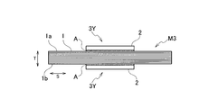
- an FRP member 1m made of fiber reinforced plastic and a resin rich sheet member 2m (sheet member) having a fiber content lower than that of the FRP member 1m are prepared.
- the FRP member 1m can be made of the same material as the material of the FRP layer 1 of the member CM, and the resin rich sheet member 2m can be made of the same material as the material of the resin rich layer 2 of the member CM.
- the adhesive A is applied to the back surface of the resin-rich sheet member 2m having a predetermined shape, and this is adhered to the upper and lower surfaces of the FRP member 1m having the predetermined shape.
- FIG. 11B an integrated adhesion structure M3 is obtained.
- the FRP member 1m constitutes the FRP layer 1
- the resin rich sheet member 2m constitutes the resin rich layer 2.
- a hole 3 is formed in the adhesive structure M3 so as to penetrate the FRP member 1m and the resin rich sheet member 2m, and the collar 4 and the washer 5 are attached to the hole 3. Since the step of forming the hole 3 and the step of mounting the collar 4 and the like are the same as the respective steps in the manufacturing method P1 described with reference to FIGS. 9A to 9C, description thereof is omitted here.
- the manufacturing method P3 since the hole 3 is formed in the bonding structure M3 in which the resin-rich sheet member 2m is bonded on the surface of the FRP member 1m, molding with a molding die is unnecessary. Compared to the method using a mold, the number of steps is small and the productivity is good.
- the reinforcing fibers F meander in the perforated portion 3Y, and the strength of the fastening portion FP of the member CM is the same as in the manufacturing method P2. Can be improved.
- an autoclave method an SMC method, a hand lay-up method, a spray-up method, or the like can be adopted as a method for manufacturing the member CM.
- the FRP layer 1 is made of fiber reinforced plastic.
- the FRP layer 1 may be made of another material (for example, a resin foam or the like).
- One or more core materials may be included as an intermediate layer.
- a decorative skin material may be provided on the surfaces 1 a and 1 b of the FRP layer 1.
- the resin rich layer 2 was formed in the area
- the resin rich layer 2 was formed in the surfaces 1a and 1b of the both sides of the FRP layer 1, the resin rich layer 2 is only the surface 1a or 1b of the one side of the FRP layer 1. May be formed.
- the cross-sectional shape of the hole 3 is not limited to a circle, and may be an oval, a rectangle, or the like.
- the composite material member CM can be used as a structural member of a vehicle such as an automobile such as a hood, a door panel, a bumper, a trunk lid, a rear gate, a fender panel, a side body panel, and a roof panel.
- the composite material member CM can be used as a constituent member of a transport device such as an aircraft, a ship, and a railway vehicle, a household electric product, a power generation facility, a production machine, a housing equipment, furniture, and a leisure article.
Landscapes
- Engineering & Computer Science (AREA)
- Mechanical Engineering (AREA)
- Chemical & Material Sciences (AREA)
- Composite Materials (AREA)
- Forests & Forestry (AREA)
- Life Sciences & Earth Sciences (AREA)
- Manufacturing & Machinery (AREA)
- Textile Engineering (AREA)
- Moulding By Coating Moulds (AREA)
- Lining Or Joining Of Plastics Or The Like (AREA)
- Perforating, Stamping-Out Or Severing By Means Other Than Cutting (AREA)
- Laminated Bodies (AREA)
- Moulds For Moulding Plastics Or The Like (AREA)
- Injection Moulding Of Plastics Or The Like (AREA)
Abstract
Description
図1A、図1B及び図2に示すように、第1実施形態にかかる部材CMは、FRP層1と、FRP層1の上側の表面1a上に形成された樹脂リッチ層2と、FRP層1の下側の表面1b上に形成された樹脂リッチ層2と、部材CMの厚さ方向Tに穿設された孔3とを備える。なお、図示した部材CMは、平板状に形成されているが、その形状は用途に応じて適宜選択可能であり、例えば、曲板状であってもよい。
Vf=100×強化繊維の体積/(強化繊維の体積+強化繊維以外の成分の体積) (1)
本実施形態の変形例では、強化繊維Fとして、長繊維、短繊維などの不連続な繊維、または連続繊維と不連続繊維との組み合わせを採用することができる。さらに、他の変形例では、強化繊維Fの一部または全部が、ランダムに配向されたものを採用することができる。これらの変形例は、部材CMの形状が複雑で高い成形性が求められる場合などに好適である。また、これらの変形例によれば、上記効果(A)、(B)及び(D)に加えて、強化繊維Fそのものの構造により、強化繊維Fの剥離をより一層抑制できるという効果を得ることができる。
次に、第2乃至第4実施形態にかかる部材CMについて、図4A乃至図6Bを参照して説明する。なお、上記において既に説明した要素と同じ機能を有する要素については、同じ符号を付し、その説明を省略する。
部材CMの製造方法P1について、図7A乃至図9Cを参照して説明する。
次に、部材CMの他の製造方法P2について、図10A乃至図10Cを参照して説明する。なお、上記において既に説明した部材と同じ機能を有する部材については、同じ符号を付し、その説明を省略する。
次に、部材CMの他の製造方法P3について、図11A及び図11Bを参照して説明する。なお、上記において既に説明した部材と同じ機能を有する部材については、同じ符号を付し、その説明を省略する。
1 FRP層
1a,1b FRP層の表面
F 強化繊維
MR マトリックス樹脂
2 樹脂リッチ層
21 第1の樹脂リッチ層
22 第2の樹脂リッチ層
22a 環状凸部
22b 島状凸部
22c 線状凸部
3 孔
4 カラー
42 フランジ
42a 裏面
G1 隙間
A 接着剤
1f 強化繊維体(強化繊維基材)
MR1 樹脂
M1 成形体(複合材料成形体)
3Y 被穿孔部
9 成形型(型)
9a,9b 成形面
91 底面(成形面)
92 突起
CV1 隙間
9c 樹脂注入口(注入口)
1p プリプレグ(第1シート状成形材料)
2p 樹脂リッチシート(第2シート状成形材料)
1m FRP部材
2m 樹脂リッチシート部材(シート部材)
Claims (12)
- 繊維強化プラスチックからなるFRP層と、
前記FRP層の表面の少なくとも一部の領域上に形成された、前記FRP層よりも繊維含有率の低い樹脂リッチ層と、
前記FRP層及び前記樹脂リッチ層を貫通するように穿設された孔と、
を備えた複合材料部材。 - 前記樹脂リッチ層が、前記FRP層の両側の表面に形成されており、
前記孔が、前記FRP層の両側の表面に形成された前記樹脂リッチ層と、前記FRP層とを貫通している、請求項1に記載の複合材料部材。 - 前記FRP層の強化繊維が連続繊維からなる、請求項1または2に記載の複合材料部材。
- 前記孔には、フランジを有するカラーが挿通されており、
前記フランジは、前記フランジの裏面と前記FRP層の表面との間の隙間に設けられた接着剤によって、前記FRP層に接着されており、
前記樹脂リッチ層は、前記FRP層の表面と前記フランジの裏面との間に介在して、前記隙間の大きさを規定している、請求項1乃至3のいずれか一項に記載された複合材料部材。 - 前記樹脂リッチ層は、前記FRP層の表面の前記フランジによって覆われた領域上に形成された、第1及び第2の樹脂リッチ層を備えており、
前記第1の樹脂リッチ層は、中央部に前記孔が穿設されており、
前記第2の樹脂リッチ層は、前記第1の樹脂リッチ層の外側に設けられている、請求項4に記載された複合材料部材。 - 前記第2の樹脂リッチ層が、前記第1の樹脂リッチ層の周囲を連続して包囲する環状凸部を構成している、請求項5に記載された複合材料部材。
- 前記第2の樹脂リッチ層が、前記第1の樹脂リッチ層の周囲を包囲する複数の島状凸部を構成している、請求項5または6に記載された複合材料部材。
- 前記第2の樹脂リッチ層が、前記第1の樹脂リッチ層から外側へ連続または不連続に延びる線状凸部を構成している、請求項5乃至7のいずれか一項に記載された複合材料部材。
- 複合材料部材の強化繊維となる強化繊維基材を型内に封入する工程と、
前記型内の前記強化繊維基材に樹脂を注入する工程と、
前記型内の前記樹脂を硬化させ、成形体を得る工程と、
前記成形体に孔を穿設する工程と、
を備え、
前記強化繊維基材を型内に封入する工程では、前記型の成形面に形成された突起により、前記強化繊維基材を前記成形面から離間した状態に保持し、
前記樹脂を注入する工程では、前記成形面から離間した状態に保持された前記強化繊維基材と前記成形面との間に形成される隙間に、前記樹脂を行き渡らせ、
前記孔を穿設する工程では、前記隙間に行き渡った樹脂が硬化したものからなる層を貫通するように、前記孔を穿設する、
複合材料部材の製造方法。 - 強化繊維基材に樹脂を含浸させてなる第1シート状成形材料と、前記第1シート状成形材料よりも繊維含有率の低い第2シート状成形材料とを、互いに重ね合わせた状態で加圧成形する工程と、
硬化した前記第1シート状成形材料からなる層と、硬化した前記第2シート状成形材料からなる層とを貫通するように孔を穿設する工程と、
を備える複合材料部材の製造方法。 - 繊維強化プラスチックからなるFRP部材の表面上に、前記FRP部材よりも繊維含有率の低いシート部材を接着する工程と、
前記FRP部材及び前記シート部材を貫通するように孔を穿設する工程と、
を備える複合材料部材の製造方法。 - 被穿孔部を有する複合材料成形体を成形するための型であって、
前記複合材料成形体の強化繊維となる強化繊維基材に樹脂を注入するための注入口と、
前記複合材料成形体の表面を成形する成形面と、
前記成形面のうち前記被穿孔部に対応する領域に形成され、前記強化繊維基材を前記成形面から離間した状態に保持する突起と、
を備えた型。
Priority Applications (5)
| Application Number | Priority Date | Filing Date | Title |
|---|---|---|---|
| EP17899723.5A EP3593990A4 (en) | 2017-03-10 | 2017-03-10 | COMPOSITE MATERIAL, METHOD FOR PRODUCING A COMPOSITE MATERIAL ELEMENT AND MOLD FOR IT |
| PCT/JP2017/009740 WO2018163411A1 (ja) | 2017-03-10 | 2017-03-10 | 複合材料部材、複合材料部材の製造方法及びその成形用型 |
| JP2019504272A JP6721107B2 (ja) | 2017-03-10 | 2017-03-10 | 複合材料部材、複合材料部材の製造方法及びその成形用型 |
| US16/484,855 US10864699B2 (en) | 2017-03-10 | 2017-03-10 | Composite material member, method for producing composite material member, and molding die for same |
| CN201780088266.8A CN110431002B (zh) | 2017-03-10 | 2017-03-10 | 复合材料构件、复合材料构件的制造方法及其成形用模具 |
Applications Claiming Priority (1)
| Application Number | Priority Date | Filing Date | Title |
|---|---|---|---|
| PCT/JP2017/009740 WO2018163411A1 (ja) | 2017-03-10 | 2017-03-10 | 複合材料部材、複合材料部材の製造方法及びその成形用型 |
Publications (1)
| Publication Number | Publication Date |
|---|---|
| WO2018163411A1 true WO2018163411A1 (ja) | 2018-09-13 |
Family
ID=63448411
Family Applications (1)
| Application Number | Title | Priority Date | Filing Date |
|---|---|---|---|
| PCT/JP2017/009740 WO2018163411A1 (ja) | 2017-03-10 | 2017-03-10 | 複合材料部材、複合材料部材の製造方法及びその成形用型 |
Country Status (5)
| Country | Link |
|---|---|
| US (1) | US10864699B2 (ja) |
| EP (1) | EP3593990A4 (ja) |
| JP (1) | JP6721107B2 (ja) |
| CN (1) | CN110431002B (ja) |
| WO (1) | WO2018163411A1 (ja) |
Cited By (1)
| Publication number | Priority date | Publication date | Assignee | Title |
|---|---|---|---|---|
| JP2020203436A (ja) * | 2019-06-18 | 2020-12-24 | スズキ株式会社 | 樹脂構造体 |
Families Citing this family (3)
| Publication number | Priority date | Publication date | Assignee | Title |
|---|---|---|---|---|
| JP2020032651A (ja) * | 2018-08-31 | 2020-03-05 | 本田技研工業株式会社 | 繊維強化樹脂成形品及びその製造方法 |
| NL2027367B1 (en) | 2021-01-22 | 2022-08-05 | Green Composites B V | Fibre-reinforced composite material |
| GB2604126A (en) * | 2021-02-24 | 2022-08-31 | Airbus Operations Ltd | Reinforced holes |
Citations (7)
| Publication number | Priority date | Publication date | Assignee | Title |
|---|---|---|---|---|
| JPH01228797A (ja) * | 1988-03-10 | 1989-09-12 | Canon Electron Inc | 積層板の穴加工方法とその装置 |
| JPH0331113U (ja) * | 1989-08-03 | 1991-03-26 | ||
| JP2002322588A (ja) * | 2001-04-25 | 2002-11-08 | Nitto Shinko Kk | マスキング材の製造方法及びマスキング材 |
| JP2009023163A (ja) * | 2007-07-18 | 2009-02-05 | Toyota Motor Corp | 繊維強化樹脂面材 |
| JP2015160393A (ja) * | 2014-02-28 | 2015-09-07 | パナソニックIpマネジメント株式会社 | 熱可塑性frpの加飾成形装置 |
| JP2016028838A (ja) * | 2014-07-25 | 2016-03-03 | 株式会社イノアックコーポレーション | 炭素繊維複合材の孔あけ加工方法 |
| JP2016114139A (ja) | 2014-12-15 | 2016-06-23 | 日産自動車株式会社 | 炭素繊維強化樹脂材の締結構造 |
Family Cites Families (8)
| Publication number | Priority date | Publication date | Assignee | Title |
|---|---|---|---|---|
| JP2000351857A (ja) | 1999-04-07 | 2000-12-19 | Toray Ind Inc | 繊維強化プラスチック製部材 |
| US20040145092A1 (en) | 2003-01-24 | 2004-07-29 | Mccollum Robert P. | Method of making a composite molded article |
| JP2004338271A (ja) * | 2003-05-16 | 2004-12-02 | Mitsubishi Rayon Co Ltd | 穿孔加工に好適な繊維強化樹脂複合材及び穿孔繊維強化樹脂複合材の製造方法 |
| US7828924B2 (en) | 2005-12-12 | 2010-11-09 | Panasonic Corporation | Intermediate material for manufacturing circuit board and method for manufacturing circuit board using such intermediate material |
| JP2009231222A (ja) | 2008-03-25 | 2009-10-08 | Ajinomoto Co Inc | 絶縁樹脂シート |
| WO2014157570A1 (ja) * | 2013-03-27 | 2014-10-02 | 三菱瓦斯化学株式会社 | 繊維強化複合材又は金属の切削加工用エントリーシート及び該切削加工方法 |
| EP3164261A4 (en) * | 2014-07-03 | 2018-02-14 | Saab Ab | A composite article having multifunctional properties and method for its manufacture |
| JP6685752B2 (ja) * | 2016-02-15 | 2020-04-22 | 三菱重工業株式会社 | 積層板及び積層板の加工方法 |
-
2017
- 2017-03-10 WO PCT/JP2017/009740 patent/WO2018163411A1/ja active Application Filing
- 2017-03-10 JP JP2019504272A patent/JP6721107B2/ja active Active
- 2017-03-10 US US16/484,855 patent/US10864699B2/en active Active
- 2017-03-10 CN CN201780088266.8A patent/CN110431002B/zh active Active
- 2017-03-10 EP EP17899723.5A patent/EP3593990A4/en active Pending
Patent Citations (7)
| Publication number | Priority date | Publication date | Assignee | Title |
|---|---|---|---|---|
| JPH01228797A (ja) * | 1988-03-10 | 1989-09-12 | Canon Electron Inc | 積層板の穴加工方法とその装置 |
| JPH0331113U (ja) * | 1989-08-03 | 1991-03-26 | ||
| JP2002322588A (ja) * | 2001-04-25 | 2002-11-08 | Nitto Shinko Kk | マスキング材の製造方法及びマスキング材 |
| JP2009023163A (ja) * | 2007-07-18 | 2009-02-05 | Toyota Motor Corp | 繊維強化樹脂面材 |
| JP2015160393A (ja) * | 2014-02-28 | 2015-09-07 | パナソニックIpマネジメント株式会社 | 熱可塑性frpの加飾成形装置 |
| JP2016028838A (ja) * | 2014-07-25 | 2016-03-03 | 株式会社イノアックコーポレーション | 炭素繊維複合材の孔あけ加工方法 |
| JP2016114139A (ja) | 2014-12-15 | 2016-06-23 | 日産自動車株式会社 | 炭素繊維強化樹脂材の締結構造 |
Non-Patent Citations (1)
| Title |
|---|
| See also references of EP3593990A4 |
Cited By (2)
| Publication number | Priority date | Publication date | Assignee | Title |
|---|---|---|---|---|
| JP2020203436A (ja) * | 2019-06-18 | 2020-12-24 | スズキ株式会社 | 樹脂構造体 |
| JP7253986B2 (ja) | 2019-06-18 | 2023-04-07 | スズキ株式会社 | 樹脂構造体 |
Also Published As
| Publication number | Publication date |
|---|---|
| US10864699B2 (en) | 2020-12-15 |
| JPWO2018163411A1 (ja) | 2020-02-27 |
| US20200055273A1 (en) | 2020-02-20 |
| CN110431002B (zh) | 2021-05-18 |
| EP3593990A4 (en) | 2020-07-29 |
| CN110431002A (zh) | 2019-11-08 |
| EP3593990A1 (en) | 2020-01-15 |
| JP6721107B2 (ja) | 2020-07-15 |
Similar Documents
| Publication | Publication Date | Title |
|---|---|---|
| WO2018163411A1 (ja) | 複合材料部材、複合材料部材の製造方法及びその成形用型 | |
| US8216501B2 (en) | Process for producing molded parts, in particular decorative part and/or trim part for the passenger compartment of a vehicle | |
| US4762740A (en) | Resin transfer molding core, preform and process | |
| JP2011143609A (ja) | インサート部品を有する繊維強化樹脂部材の製造方法 | |
| JP5681617B2 (ja) | ナット付き繊維強化樹脂部材の製造方法 | |
| JP5611365B2 (ja) | 繊維強化プラスチック成形体の製造方法、プリフォームおよびその製造方法、ならびに、接着フィルム | |
| US10155331B2 (en) | Method of producing fiber-reinforced resin-molded member, and method of connecting members | |
| US20160332395A1 (en) | Frp shaping jig and method of shaping frp structure | |
| JP6294298B2 (ja) | プラスチック材料から車両構成要素/構造構成要素を製造するための方法 | |
| JP2015178241A (ja) | 繊維強化樹脂材の製造方法 | |
| EP2650096A1 (en) | Method for manufacturing composite material | |
| US7374715B2 (en) | Co-cured resin transfer molding manufacturing method | |
| US20140186574A1 (en) | Method for producing and connecting fibre-reinforced components and aircraft or spacecraft | |
| EP3492251B1 (en) | Method for producing a composite component | |
| US9539769B2 (en) | Composite structure and core positioning ply | |
| KR101857959B1 (ko) | 림 제조용 몰드 및 이를 이용한 림 제조방법 | |
| JP2008068587A (ja) | Frp製成形品、その成形方法並びにその成形型 | |
| JP2002248620A (ja) | 繊維強化プラスチック成形用基材および繊維強化プラスチックの成形方法 | |
| JP2007015187A (ja) | Frp成形物 | |
| JP5238152B2 (ja) | 積層体およびこれを用いた自動車用ボンネット | |
| JP5605267B2 (ja) | 繊維強化樹脂材とその製造方法 | |
| JP6564530B2 (ja) | 繊維強化樹脂成形体およびその製造方法 | |
| WO2023062870A1 (ja) | 金属-プリプレグ複合体 | |
| JP7395219B1 (ja) | 繊維強化樹脂中空又は複合成形体 | |
| KR20190055376A (ko) | 차량용 필러 보강재 및 이의 제조방법 |
Legal Events
| Date | Code | Title | Description |
|---|---|---|---|
| 121 | Ep: the epo has been informed by wipo that ep was designated in this application |
Ref document number: 17899723 Country of ref document: EP Kind code of ref document: A1 |
|
| ENP | Entry into the national phase |
Ref document number: 2019504272 Country of ref document: JP Kind code of ref document: A |
|
| NENP | Non-entry into the national phase |
Ref country code: DE |
|
| WWE | Wipo information: entry into national phase |
Ref document number: 2017899723 Country of ref document: EP |
|
| ENP | Entry into the national phase |
Ref document number: 2017899723 Country of ref document: EP Effective date: 20191010 |