WO2018159792A1 - ブレーキ制御装置 - Google Patents
ブレーキ制御装置 Download PDFInfo
- Publication number
- WO2018159792A1 WO2018159792A1 PCT/JP2018/007916 JP2018007916W WO2018159792A1 WO 2018159792 A1 WO2018159792 A1 WO 2018159792A1 JP 2018007916 W JP2018007916 W JP 2018007916W WO 2018159792 A1 WO2018159792 A1 WO 2018159792A1
- Authority
- WO
- WIPO (PCT)
- Prior art keywords
- pressure
- control
- pressure increase
- estimated value
- deviation
- Prior art date
- Legal status (The legal status is an assumption and is not a legal conclusion. Google has not performed a legal analysis and makes no representation as to the accuracy of the status listed.)
- Ceased
Links
Images




Classifications
-
- B—PERFORMING OPERATIONS; TRANSPORTING
- B60—VEHICLES IN GENERAL
- B60T—VEHICLE BRAKE CONTROL SYSTEMS OR PARTS THEREOF; BRAKE CONTROL SYSTEMS OR PARTS THEREOF, IN GENERAL; ARRANGEMENT OF BRAKING ELEMENTS ON VEHICLES IN GENERAL; PORTABLE DEVICES FOR PREVENTING UNWANTED MOVEMENT OF VEHICLES; VEHICLE MODIFICATIONS TO FACILITATE COOLING OF BRAKES
- B60T8/00—Arrangements for adjusting wheel-braking force to meet varying vehicular or ground-surface conditions, e.g. limiting or varying distribution of braking force
- B60T8/17—Using electrical or electronic regulation means to control braking
- B60T8/172—Determining control parameters used in the regulation, e.g. by calculations involving measured or detected parameters
-
- B—PERFORMING OPERATIONS; TRANSPORTING
- B60—VEHICLES IN GENERAL
- B60T—VEHICLE BRAKE CONTROL SYSTEMS OR PARTS THEREOF; BRAKE CONTROL SYSTEMS OR PARTS THEREOF, IN GENERAL; ARRANGEMENT OF BRAKING ELEMENTS ON VEHICLES IN GENERAL; PORTABLE DEVICES FOR PREVENTING UNWANTED MOVEMENT OF VEHICLES; VEHICLE MODIFICATIONS TO FACILITATE COOLING OF BRAKES
- B60T8/00—Arrangements for adjusting wheel-braking force to meet varying vehicular or ground-surface conditions, e.g. limiting or varying distribution of braking force
- B60T8/17—Using electrical or electronic regulation means to control braking
- B60T8/176—Brake regulation specially adapted to prevent excessive wheel slip during vehicle deceleration, e.g. ABS
- B60T8/1761—Brake regulation specially adapted to prevent excessive wheel slip during vehicle deceleration, e.g. ABS responsive to wheel or brake dynamics, e.g. wheel slip, wheel acceleration or rate of change of brake fluid pressure
-
- B—PERFORMING OPERATIONS; TRANSPORTING
- B62—LAND VEHICLES FOR TRAVELLING OTHERWISE THAN ON RAILS
- B62L—BRAKES SPECIALLY ADAPTED FOR CYCLES
- B62L3/00—Brake-actuating mechanisms; Arrangements thereof
- B62L3/02—Brake-actuating mechanisms; Arrangements thereof for control by a hand lever
Definitions
- Embodiments of the present invention relate to a brake control device.
- a pumping brake that repeats a series of operations in which a brake operation is once released and then a brake operation is performed again is known as a manual driving operation technique for suppressing wheel lock. .
- one of the problems of the embodiment is that the brake capable of suppressing the occurrence of inconsistency between the driver's brake operation and the actually generated braking force when the pumping brake is performed together with the antilock control. It is to provide a control device.
- the brake control device is, for example, a brake control device that controls a brake mechanism that generates a braking force by applying pressure to the wheels of the vehicle, and includes a pressure reduction control that reduces the pressure during braking of the vehicle.
- a brake control device Acquiring the output value of the sensor that detects the information related to the running state of the vehicle, and the control unit that executes the anti-lock control that suppresses the lock of the wheel by executing at least the pressure increasing control that increases the pressure
- a second method based on the output value and the control state of the antilock control while calculating the first estimated value of the deceleration occurring in the vehicle by the first method based only on the output value
- a calculation unit that calculates a second estimated value of deceleration, and the control unit is configured to execute a pressure increase control when the deviation between the first estimated value and the second estimated value is the first deviation.
- Pressure increase Distribution is deviation to be greater than the pressure increase gradient in time a small second deviation than the first deviation, corrects the pressure increase gradient. As a result, even when the pumping brake is performed together with the anti-lock control, the pressure increase gradient is corrected according to the deviation between the first estimated value and the second estimated value. It is possible to suppress the occurrence of mismatch with the braking force.
- FIG. 1 is an exemplary block diagram showing a configuration of a vehicle brake system according to the first embodiment.
- FIG. 2 is an exemplary block diagram showing a functional configuration of the brake control device according to the first embodiment.
- FIG. 3 is an exemplary graph for explaining a method of estimating the wheel cylinder pressure during pressure reduction control in the first embodiment.
- FIG. 4 is an exemplary graph for explaining a method of estimating the wheel cylinder pressure during the pressure increase control in the first embodiment.
- FIG. 5 is an exemplary diagram showing an example of a means for realizing a desired pressure increasing gradient in the first embodiment.
- FIG. 6 is an exemplary graph showing an example of a pressure increasing gradient realized by the means shown in FIG. 5 in the first embodiment.
- FIG. 1 is an exemplary block diagram showing a configuration of a vehicle brake system according to the first embodiment.
- FIG. 2 is an exemplary block diagram showing a functional configuration of the brake control device according to the first embodiment.
- FIG. 3 is an exemplary graph for explaining a method of estimating the
- FIG. 7 is an exemplary flowchart showing a process executed by the brake control device according to the first embodiment during the antilock control.
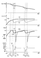
- FIG. 8 is an exemplary timing chart for explaining the brake control according to the comparative example.
- FIG. 9 is an exemplary timing chart for explaining the brake control according to the first embodiment.
- FIG. 10 is an exemplary timing chart for explaining the effectiveness of the brake control according to the first embodiment.
- FIG. 11 is an exemplary timing chart for explaining the brake control according to the second embodiment.
- FIG. 1 is an exemplary block diagram illustrating a configuration of a brake system 1 of a vehicle 10 according to an embodiment.
- the vehicle 10 according to the embodiment is a two-wheeled vehicle
- the technique of the embodiment can be applied to a general vehicle such as a four-wheeled vehicle.
- the brake system 1 includes a brake mechanism 110 that generates a braking force by applying pressure to the front wheels 2F, and a brake mechanism 120 that generates a braking force by applying pressure to the rear wheels 2R. And a brake control device 200 that controls the brake mechanism 110 on the front wheel 2F side.
- the brake mechanism 120 on the rear wheel 2R side applies a master cylinder 122 that pressurizes according to the operation of the brake pedal 121, and pressurizes the friction braking member based on the pressure (hydraulic pressure) from the master cylinder 122 to A wheel cylinder 123 for braking.
- the brake mechanism 110 on the front wheel 2F side presses the front wheel 2F by pressurizing the friction brake member based on the master cylinder 112 that pressurizes according to the operation of the brake lever 111 and the pressure (hydraulic pressure) from the master cylinder 112.
- a wheel cylinder 123 for braking and a hydraulic pressure control circuit 124 provided between the master cylinder 112 and the wheel cylinder 123 are provided.
- the hydraulic pressure control circuit 124 includes a hydraulic pressure adjusting unit 125 that adjusts the hydraulic pressure applied to the wheel cylinder 123, and a reflux mechanism 126 that returns the fluid on the downstream side (wheel cylinder 123 side) to the upstream side (master cylinder 112 side). , Including.
- the hydraulic pressure adjusting unit 125 includes a pressure increasing valve 125a and a pressure reducing valve 125b that electrically switch between an open state and a closed state, and a check valve 125c provided in parallel to the pressure increasing valve 125a.
- the reflux mechanism 126 includes a reservoir 126a that temporarily stores brake fluid (fluid), a pump 126b that pumps fluid from the reservoir 126a, and a motor 126c that drives the pump 126b.
- the pressure increasing valve 125a is provided between the wheel cylinder 123 and the master cylinder 112, and the pressure reducing valve 125b is provided between the wheel cylinder 123 and the reservoir 126a.
- the brake control device 200 is a control unit including hardware similar to a normal computer such as a processor and a memory.
- the brake control device 200 is realized as an ECU (Electronic Control Unit), for example.
- the brake control device 200 increases or maintains the pressure (braking force) generated in the wheel cylinder 123 of the front wheel 2F by controlling the pressure increasing valve 125a, the pressure reducing valve 125b, and the motor 126c of the brake mechanism 110. Or depressurize. As a result, the brake control device 200 can execute anti-lock control that prevents the front wheel 2F from being locked during braking of the vehicle 10.
- 1ch ABS Antilock Blanking System
- the technology of the embodiment can also be applied to an ABS of 2ch or more. is there.
- the brake control device 200 uses the output values of various sensors such as a wheel speed sensor 301 that detects the rotational speed of the front wheel 2F and an acceleration sensor 302 that detects the longitudinal acceleration generated in the vehicle 10 for control. can do.
- VWF represents the rotational speed of the front wheel 2 ⁇ / b> F
- Gx represents the longitudinal acceleration generated in the vehicle 10.
- the anti-lock control is generally executed when a slip of the wheel during braking of the vehicle 10 is detected based on a change in the output value of the wheel speed sensor 301 or the like.
- the antilock control is realized by a combination of a pressure reduction control for reducing the pressure (braking force) applied to the wheel, a pressure increase control for increasing the pressure, and a holding control for holding the pressure.
- pressure reduction control when wheel slip is detected, first, pressure reduction control is executed. And when the fall of the rotational speed of a wheel is eased by pressure reduction control, a control state switches from pressure reduction control to holding control. When the rotation speed of the wheel starts to be recovered by the holding control, the control state is switched from the holding control to the pressure increasing control, and the pressure increasing control is executed until the wheel slip is detected again.
- the pressure increase control in order to ensure a certain level of braking force at an early stage, first, sudden pressure increase control with a relatively large pressure increase gradient was executed, and after that, sufficient braking force of a certain level or more was ensured. In order to maintain the state for a longer time, the slow pressure increase control with a relatively small pressure increase gradient is executed.
- a pumping brake that repeats a series of operations in which a brake operation is once released and then a brake operation is performed again is known as a manual driving operation technique for suppressing wheel lock. .
- a pumping brake is performed together with the conventional antilock control as described above, the following inconvenience may occur.
- the brake control device 200 has a configuration as described below, so that even when the pumping brake is performed together with the pressure increase control of the antilock control, the brake operation of the driver and the braking force actually generated are generated. It is possible to suppress the occurrence of inconsistency.
- FIG. 2 is an exemplary block diagram showing a functional configuration of the brake control device 200 according to the embodiment.
- the brake control device 200 includes an acquisition unit 201, a calculation unit 202, and a control unit 203.
- These functional configurations are realized, for example, as a result of execution of software (program) stored in a memory by the processor of the brake control device 200.
- part or all of these functional configurations may be realized by dedicated hardware (circuit).
- the acquisition unit 201 receives (acquires) output values of sensors such as the wheel speed sensor 301 and the acceleration sensor 302 that detect the traveling state of the vehicle 10 via the in-vehicle network.
- the in-vehicle network is, for example, a CAN (Controller Area Network).
- the calculation unit 202 estimates the deceleration generated in the vehicle 10 based on the output value of the acceleration sensor 302 acquired by the acquisition unit 201 and the control state of the antilock control by two methods.
- the control state represents various types of control that can be executed during the antilock control, such as the above-described pressure reduction control or pressure increase control.
- the calculation unit 202 calculates the first estimated value of the deceleration of the vehicle 10 by the first method based only on the output value of the acceleration sensor 302. As described above, since the acceleration sensor 302 detects the acceleration of the vehicle 10, according to the output value of the acceleration sensor 302, the first estimated value of the deceleration of the vehicle 10 is directly calculated (acquired). can do.
- the calculation unit 202 calculates a second estimated value of the deceleration of the vehicle 10 by a second method based on the output value of the acceleration sensor 302 and the control state of the antilock control.
- the second method includes a step of estimating a pressure applied to the front wheel 2F by the wheel cylinder 123 (hereinafter referred to as wheel cylinder pressure).
- the second method when the control state is the pressure reduction control will be described.
- the braking force generated in the front wheel 2F at the start of the pressure reduction control that is, the wheel cylinder pressure of the front wheel 2F at the start of the pressure reduction control is estimated.
- the second estimated value at the start time of the pressure reduction control is calculated by converting the wheel cylinder pressure at the start time of the pressure reduction control into the deceleration.
- the wheel cylinder pressure is estimated by the following method, and the second estimated value is calculated based on the estimated wheel cylinder pressure.
- FIG. 3 is an exemplary graph for explaining a method of estimating the wheel cylinder pressure during pressure reduction control in the first embodiment.
- the graph of FIG. 3 represents the relationship between the execution time of the pressure reduction control and the wheel cylinder pressure (WC pressure).
- WC pressure wheel cylinder pressure
- the wheel cylinder pressure at a certain time point t1 is P1
- the wheel cylinder pressure at can be estimated and a second estimated value can be calculated.
- the second estimated value can be calculated by the same calculation method as when the control state is the pressure reduction control. That is, when the control state is the rapid pressure increase control, the second estimated value at the start time of the rapid pressure increase control is calculated based on the wheel cylinder pressure of the front wheel 2F at the time of the start of the rapid pressure increase control.
- the wheel cylinder pressure at the start of the sudden pressure increase control is an estimated value of the wheel cylinder pressure at the end of the pressure reduction control. Good.
- the wheel cylinder pressure is estimated by the following method, and the second estimated value is calculated based on the estimated wheel cylinder pressure.
- FIG. 4 is an exemplary graph for explaining a method of estimating the wheel cylinder pressure during the rapid pressure increase control in the first embodiment.
- the graph of FIG. 4 represents the relationship between the execution time of the rapid pressure increase control and the wheel cylinder pressure (WC pressure).
- WC pressure wheel cylinder pressure
- the information as in the graph of FIG. 4 can be obtained in advance by calculation or experiment. Therefore, in the first embodiment, it is assumed that information such as the graph of FIG. 4 is stored in advance in a memory or the like in addition to the information such as the graph of FIG.
- the wheel cylinder pressure is controlled to increase at a predetermined pressure increase gradient (pressure increase speed) as described later. Therefore, the wheel cylinder pressure during the slow pressure increase control is calculated based on the estimated value of the wheel cylinder pressure at the end of the sudden pressure increase control as the wheel cylinder pressure at the start of the slow pressure increase control. It can be easily estimated from the wheel cylinder pressure at the start time, the pressure increase gradient set in the slow pressure increase control, and the execution time of the slow pressure increase control. For example, by increasing the pressure increase gradient during the slow pressure increase control and the execution time of the slow pressure increase control, the wheel cylinder pressure increases from the start point of the slow pressure increase control to the target time (for example, the current time). By calculating the amount and adding the calculated increase amount to the wheel cylinder pressure at the start of the slow pressure increase control, the wheel cylinder pressure at the target time can be estimated. The second estimated value can be calculated based on the wheel cylinder pressure estimated by such a method.
- the second estimated value is based on the wheel cylinder pressure estimated according to information set in advance according to the control state of the antilock control. Therefore, unlike the first estimated value corresponding to the actual traveling state of the vehicle 10, the second estimated value may not reflect the actual traveling state of the vehicle 10. For example, when the brake operation in the pumping brake is released while the anti-lock control pressure increase control (slow pressure increase control) is being executed, the first estimated value approaches zero according to the release of the brake operation. On the other hand, the second estimated value changes (relatively slowly) according to the pressure increase control regardless of the release of the brake operation. For this reason, when the pumping brake is performed together with the antilock control, the deviation between the first estimated value and the second estimated value is considered to be relatively large.
- the first estimated value that is the deceleration is clearly smaller than the second estimated value that is the deceleration (the deceleration represented by the second estimated value). It is considered that the degree of deceleration represented by the first estimated value is smaller than the degree of.
- the control unit 203 monitors the deviation between the first estimated value and the second estimated value during execution of the pressure increase control, and when the deviation exceeds the threshold value, By executing the following processing, the occurrence of inconsistency between the brake operation of the driver and the braking force actually generated is suppressed.
- the desired effect can be obtained at an earlier stage if the threshold value is set as small as possible. However, if the threshold value is set too small, the influence of the operation not related to the original aim such as the braking operation on the rear wheel 2R side. Thus, the deviation may exceed a threshold value. Therefore, the threshold value is set as small as possible within a range not affected by the braking operation on the rear wheel 2R side.
- the control unit 203 increases the wheel cylinder pressure according to the magnitude of the deviation. Correct (adjust) the pressure gradient. More specifically, when the deviation between the first estimated value and the second estimated value is the first deviation, the control unit 203 determines that the pressure increase gradient is a second deviation that is smaller than the first deviation. The pressure increase gradient is corrected so as to be larger than the pressure increase gradient at.
- control unit 203 may correct the pressure increase gradient so that the pressure increase gradient increases as the deviation between the first estimated value and the second estimated value increases.
- the pressure increase gradient may be corrected based on the maximum deviation in the interval.
- FIG. 5 is an exemplary diagram showing an example of specific means for realizing a desired pressure increasing gradient in the first embodiment
- FIG. 6 is shown in FIG. 5 in the first embodiment. It is an exemplary graph which showed the example of the pressure increase gradient implement
- a cycle composed of increasing the wheel cylinder pressure and maintaining the wheel cylinder pressure is repeated a plurality of times at a constant period ⁇ , so that a desired An increasing pressure gradient is realized.
- the pressure increase is realized by an instruction (output) for opening the pressure increase valve 125a, and the holding is realized by an instruction (output) for closing the pressure increase valve 125a.
- the fourth and subsequent cycles are not shown.
- ⁇ 111 and ⁇ 112 respectively represent the pressure increase and holding execution times in the first cycle for realizing the pressure increase gradient X1.
- ⁇ 121 and ⁇ 122 represent the pressure increasing and holding execution times in the second cycle for realizing the pressure increasing gradient X1, respectively.
- ⁇ 131 and ⁇ 132 respectively represent the pressure increase and holding execution times in the third cycle for realizing the pressure increase gradient X1. It is assumed that the sum of ⁇ 111 and ⁇ 112, the sum of ⁇ 121 and ⁇ 122, and the sum of ⁇ 131 and ⁇ 132 are equal and coincide with the above-mentioned period ⁇ . According to these cycles, it is possible to obtain a change in the wheel cylinder pressure approximated to the solid line L11 representing the pressure increase gradient X1, such as the one-dot chain line L10 in the example of FIG.
- ⁇ 211 and ⁇ 212 respectively represent the pressure increasing and holding execution times in the first cycle for realizing the pressure increasing gradient X2.
- ⁇ 221 and ⁇ 222 respectively represent execution times of pressure increase and holding in the second cycle for realizing the pressure increase gradient X2.
- ⁇ 231 and ⁇ 232 represent the execution time of pressure increase and holding in the third cycle for realizing the pressure increase gradient X2, respectively. It is assumed that the sum of ⁇ 211 and ⁇ 212, the sum of ⁇ 221 and ⁇ 222, and the sum of ⁇ 231 and ⁇ 232 are the same and coincide with the above-mentioned period ⁇ . According to these cycles, a change in the wheel cylinder pressure approximated to the solid line L21 representing the pressure increase gradient X2, such as the two-dot chain line L20 in the example of FIG. 6, can be obtained.
- the information as shown in FIG. 5 in which the execution time of pressure increase and holding for each cycle is set according to various pressure increase gradients is stored in advance in the form of a table, a map, or the like. .
- the various pressure increase gradients according to the deviation of a 1st estimated value and a 2nd estimated value are easily realizable.
- FIG. 7 is an exemplary flowchart showing processing executed by the brake control device 200 according to the first embodiment during anti-lock control.
- the series of processing shown in FIG. 7 is repeatedly executed during antilock control.
- the calculation unit 202 of the brake control device 200 first calculates the first estimated value of the deceleration of the vehicle 10 in S ⁇ b> 1 by the first method based only on the output value of the acceleration sensor 302. To do.
- the calculation part 202 calculates the 2nd estimated value of the deceleration of the vehicle 10 with the 2nd method based on the output value of the acceleration sensor 302, and the control state of anti-lock control.
- the control unit 203 calculates a deviation between the first estimated value calculated in S1 and the second estimated value calculated in S2. More specifically, the control unit 203 obtains the deviation by subtracting the first estimated value calculated in S1 from the second estimated value calculated in S2. In this case, for example, when the first estimated value is larger than the second estimated value, the control unit 203 may set the deviation to 0 (zero).
- control unit 203 determines whether or not the deviation calculated in S3 exceeds a threshold value.
- control unit 203 calculates a correction coefficient for correcting the pressure increase gradient of the wheel cylinder pressure based on the deviation calculated in S3. More specifically, the control unit 203 satisfies the condition that the pressure increase gradient when the deviation is the first deviation is larger than the pressure increase gradient when the deviation is the second deviation smaller than the first deviation. Such a correction coefficient is calculated.
- control unit 203 corrects the pressure increase gradient based on the correction coefficient calculated in S5. And the control part 203 performs pressure increase control (slow pressure increase control) according to the information of FIG. 5 corresponding to the corrected pressure increase gradient, and the process ends.
- the brake control according to the following timing chart is realized.
- the brake control according to the first embodiment will be described in comparison with the brake control according to the comparative example.
- This comparative example is an example in which the correction of the pressure increase gradient based on the deviation between the first estimated value and the second estimated value as in the first embodiment is not executed.
- FIG. 8 is an exemplary timing chart for explaining the brake control according to the comparative example.
- a solid line L101 represents a time change of the vehicle speed (corresponding to the speed of the vehicle 10 in the first embodiment)
- a solid line L102 is a time of wheel speed (corresponding to the rotational speed of the front wheel 2F in the first embodiment). Represents change.
- the solid line L103 represents the change over time of the estimated value of the master cylinder pressure (MC pressure, corresponding to the pressure of the master cylinder 112 on the front wheel 2F side in the first embodiment).
- a solid line L104 represents a temporal change in an estimated value of the wheel cylinder pressure (WC pressure, corresponding to the pressure of the wheel cylinder 123 on the front wheel 2F side in the first embodiment), and a one-dot chain line L104a represents a wheel that causes the wheel to be locked. This represents a lock pressure P100 that is a cylinder pressure.
- a dotted line L105 represents a temporal change in deceleration (corresponding to the first estimated value in the first embodiment) calculated based on the running state of the vehicle
- a solid line L106 represents a temporal change in the control state of the antilock control. Represents.
- the pressure reduction control When the pressure reduction control is started at the timing T101, the wheel cylinder pressure is reduced along with the pressure reduction control (see the solid line L104), and the drop of the wheel speed is substantially stopped at the timing T102 (see the solid line L102). Thereby, it is determined that it is not necessary to further reduce the wheel cylinder pressure, and the pressure reduction control shifts to the holding control at timing T102 (see the solid line L106).
- the wheel cylinder pressure increases with a pressure increase gradient preset by the rapid pressure increase control (see the solid line L104). Then, at the timing T104 when the pressure increase amount, which is the increase amount of the wheel cylinder pressure, reaches a predetermined amount (or when a predetermined time has elapsed), the sudden pressure increase control shifts to the slow pressure increase control (see the solid line L106). As a result, after timing T104, the wheel cylinder pressure gradually rises at a pressure increase gradient that is less than the pressure increase gradient of the rapid pressure increase control that is set in advance in the slow pressure increase control (see the solid line L104).
- the brake operation is performed again at timing T108.
- the operation of the brake mechanism starts again, and the master cylinder pressure increases (see solid line L103).
- the wheel cylinder pressure is related to the amount of brake operation until the timing T109 when the wheel cylinder pressure approaches the lock pressure P100 again.
- the pressure increases only with a gentle pressure increase gradient set in advance by the slow pressure increase control (see the solid line L104). Therefore, in the example of FIG. 8, inconsistency between the driver's braking operation and the actually generated braking force may occur after timing T108.
- the subsequent operations at timings T109 to T112 are the same as the operations at timings T101 to T104, respectively, and thus description thereof is omitted here.
- the pumping brake is performed together with the pressure increasing control of the antilock control.
- a mismatch between the brake operation of the driver and the actually generated braking force may occur.
- the pressure increasing gradient is corrected based on the deviation between the first estimated value and the second estimated value.
- FIG. 9 is an exemplary timing chart for explaining the brake control according to the first embodiment.
- a solid line L201 represents a temporal change in the speed (vehicle speed) of the vehicle 10
- a solid line L202 represents a temporal change in the rotational speed (wheel speed) of the front wheel 2F.
- a solid line L203 represents a change over time of an estimated value of the pressure (master cylinder pressure, MC pressure) of the master cylinder 112 on the front wheel 2F side.
- a solid line L204 represents a temporal change in an estimated value of the pressure (wheel cylinder pressure, WC pressure) of the wheel cylinder 123 on the front wheel 2F side, and
- a one-dot chain line L204a represents a lock pressure that is a wheel cylinder pressure that causes the front wheel 2F to be locked.
- P200 is represented.
- a dotted line L205 represents a temporal change in the first estimated value of the deceleration of the vehicle 10 calculated by the first method based only on the output value of the acceleration sensor 302, and a solid line L205a represents the output value of the acceleration sensor 302.
- the time change of the 2nd estimated value of the deceleration of the vehicle 10 calculated by the 2nd method based on the control state of anti-lock control is represented.
- a solid line L206 represents a temporal change in the control state of the antilock control.
- the master cylinder pressure and the wheel cylinder pressure rise in response to the first brake operation from timing T200 to timing T201 (see solid lines L203 and L204).
- the first estimated value based on the actual traveling state of the vehicle 10 and the second estimated value based on the estimated value of the wheel cylinder pressure both increase (see the dotted line L205 and the solid line L205a).
- the pressure reduction control When the pressure reduction control is started at the timing T201, the wheel cylinder pressure is reduced along with the pressure reduction control (see the solid line L204), and the drop of the wheel speed is substantially stopped at the timing T202 (see the solid line L202). During this time, the vehicle 10 is in a slip state with the front wheel 2F locked. Therefore, even if the wheel cylinder pressure decreases, the first estimated value that is a deceleration obtained only from the output value of the acceleration sensor 302 does not substantially change (see the dotted line L205). On the other hand, the second estimated value is obtained by converting the wheel cylinder pressure into a deceleration. Therefore, when the wheel cylinder pressure decreases, the second estimated value decreases as the wheel cylinder pressure decreases (see the solid line L205a). Then, when the drop of the wheel speed substantially stops at timing T202, the pressure reduction control shifts to the holding control (see the solid line L206).
- the wheel cylinder pressure is maintained as it is (see solid line L204), and a recovery (increase) tendency of the wheel speed is seen at timing T203 (see solid line L202).
- the first estimated value does not substantially change as described above (see the dotted line L205).
- the second estimated value does not change as the wheel cylinder pressure is maintained (see the solid line L205a).
- the rapid pressure increase control When the rapid pressure increase control is started at timing T203, the wheel cylinder pressure increases with a pressure increase gradient preset by the rapid pressure increase control (see the solid line L204). Then, at the timing T204 when the wheel cylinder pressure increase amount (pressure increase amount) reaches a predetermined amount, the rapid pressure increase control shifts to the slow pressure increase control (see the solid line L206). As a result, after timing T204, the wheel cylinder pressure gradually rises with a pressure increase gradient that is gentler than the pressure increase gradient of the sudden pressure increase control set in advance in the slow pressure increase control (see the solid line L204). The deviation from the wheel speed is gradually reduced (see solid lines L201 and L202).
- the first estimated value gradually decreases as slip is resolved due to the coincidence between the vehicle speed and the wheel speed (see the dotted line L205).
- the second estimated value increases so as to correspond to the increase in wheel cylinder pressure (see solid line L205a).
- the first estimated value decreases (see the dotted line L205).
- the second estimated value reflects the control state of the anti-lock control on the assumption that the master cylinder pressure is maintained at a predetermined value regardless of the brake operation, so that the release of the brake operation is started.
- the pressure continues to rise gradually with a gentle pressure increase gradient preset by the slow pressure increase control (see solid line L205a). Therefore, after the timing T206 when the first estimated value and the second estimated value intersect, the deviation between the first estimated value and the second estimated value gradually increases (both directions between the dotted line L205 and the solid line L205a). See arrow).
- the wheel cylinder in the pressure increase control of the antilock control according to the deviation when the deviation between the first estimated value and the second estimated value exceeds the threshold value, the wheel cylinder in the pressure increase control of the antilock control according to the deviation.
- the pressure increase gradient is corrected.
- the pressure increase gradient may be corrected so as to increase as the deviation increases, or may be corrected based on the maximum value of the deviation in a predetermined section from the time when the deviation exceeds the threshold. As an example, an example in which the pressure increase gradient is corrected as in the former will be described.
- the correction of the pressure increase gradient of the wheel cylinder pressure in the pressure increase control is started at a timing T207 when the deviation between the first estimated value and the second estimated value exceeds the threshold value.
- the pressure increase gradient is larger than the pressure increase gradient at the timing T207. That is, assuming that the pressure increase gradient at timing T207 is the first pressure increase gradient (pressure increase gradient in the normal slow pressure increase control) and the pressure increase gradient at timing T208 is the second pressure increase gradient, the second pressure increase gradient. > The magnitude relationship of the first pressure increase gradient is established.
- the deviation between the first estimated value and the second estimated value is further reduced (see the double-pointed arrow between the dotted line L205 and the solid line L205a).
- the correction of the pressure increase gradient is finished, and the wheel cylinder pressure increases with the normal pressure increase gradient (see solid line L204). This normal pressure increasing gradient is maintained as it is until the timing T213 when the wheel cylinder pressure approaches the lock pressure P200 again.
- the operations at timings T213 to T216 are the same as the operations at timings T201 to T204, respectively, and the operations at timings T217 to T220 are also the same as the operations at timings T201 to T204, respectively. To do.
- the correction of the pressure increase gradient based on the deviation between the first estimated value and the second estimated value is executed, so that the pumping is performed together with the pressure increasing control of the antilock control. Even when a brake (more specifically, a brake operation after releasing the brake operation) is performed, the wheel cylinder pressure quickly increases in response to the driver's brake operation. It is possible to suppress the occurrence of mismatch with the braking force generated in the vehicle.
- the correction of the pressure increase gradient according to the first embodiment is not executed in the following situation where it is not necessary to correct the pressure increase gradient, and thus functions effectively in this respect.
- FIG. 10 is an exemplary timing chart for explaining the effectiveness of the brake control according to the first embodiment.
- a solid line L301 represents a time change in the speed (vehicle speed) of the vehicle 10
- a solid line L302 represents a time change in the rotational speed (wheel speed) of the front wheel 2F.
- a solid line L303 represents a temporal change in the estimated value of the pressure (master cylinder pressure, MC pressure) of the master cylinder 112 on the front wheel 2F side
- a solid line L304 represents the pressure (wheel cylinder pressure, It represents the time change of the estimated value of (WC pressure).
- a one-dot chain line L304a represents a lock pressure P300a that is a wheel cylinder pressure that causes the front wheel 2F to be locked on a road surface (high ⁇ road) having a relatively high road resistance
- a two-dot chain line L304b represents a road resistance.
- a dotted line L305 represents a time change of the first estimated value of the deceleration of the vehicle 10 calculated by the first method based only on the output value of the acceleration sensor 302, and a solid line L305a represents the output value of the acceleration sensor 302.
- the time change of the 2nd estimated value of the deceleration of the vehicle 10 calculated by the 2nd method based on the control state of anti-lock control is represented.
- a solid line L306 represents a temporal change in the control state of the antilock control.
- timing T300 In the example of FIG. 10, it is assumed that a normal brake operation that is not a pumping brake is started at timing T300. In the example of FIG. 10, it is assumed that the traveling road surface of the vehicle 10 changes from a high ⁇ road to a low ⁇ road at timing T305.
- the operations at timings T300 to T304 are the same as the operations at timings T200 to T204 in FIG. 9 described above, so the operations after timing T305 will be described below.
- the wheel cylinder pressure is reduced along with the pressure reduction control (see the solid line L304), and the drop of the wheel speed is substantially stopped at the timing T307 (see the solid line L302).
- the second estimated value obtained by converting the wheel cylinder pressure into the deceleration decreases as the wheel cylinder pressure decreases (see the solid line L305a).
- the first estimated value which is a deceleration obtained only from the output value of the acceleration sensor 302, does not substantially change as in the example of FIG. 9 described above unless the road resistance changes, but in the example of FIG.
- the road surface resistance is reduced at timing T305. Therefore, in the example of FIG. 10, in a predetermined section after timing T305, the first estimated value also decreases by a predetermined amount in accordance with the decrease in road resistance (see dotted line L305).
- the second estimated value when the first estimated value decreases from the timing T306 to the timing T307, the second estimated value also greatly decreases. Therefore, in this case, since the deviation between the first estimated value and the second estimated value does not exceed the threshold value, correction of the pressure increase gradient according to the deviation is not started.
- the traveling road surface changes from a high ⁇ road to a low ⁇ road
- the wheel cylinder pressure does not increase with a pressure increase gradient larger than usual.
- the operation at the timings T307 to T309 is substantially the same as the operation at the timings T302 to T304 except that the lock pressure P300a is changed to the lock pressure P300b, and thus the description thereof is omitted here.
- the operations at timings T310 to T313 are the same as the operations at timings T307 to T309, respectively, and thus description thereof is omitted here.
- the description of operations after timing T314, after T315, and after T316 is also omitted.
- the road surface is changed from a high ⁇ road to a low ⁇ road by monitoring whether or not the deviation between the first estimated value and the second estimated value is equal to or greater than a threshold value. Therefore, it is possible to avoid erroneously determining that the decrease in the deceleration of the vehicle due to this is a pumping brake. Thereby, it is possible to avoid the correction of the pressure increase gradient in a situation where it is not necessary to correct the pressure increase gradient.
- the master cylinder pressure is low. It is assumed that the wheel cylinder pressure does not increase at the assumed pressure increase gradient and that the vehicle deceleration is low.
- the difference between the second estimated value calculated on the assumption that the pressure increases with a predetermined pressure increase gradient and the first estimated value indicating the deceleration of the vehicle is increased. The pressure gradient is corrected and switching to a higher pressure increasing gradient is performed. Therefore, the first embodiment is also effective in this respect.
- the example in which the first estimated value of the deceleration of the vehicle 10 is calculated using only the output value of the acceleration sensor 302 has been described.
- the first estimated value is a deceleration, it can be obtained from the vehicle speed calculated from the wheel speed. Therefore, in the following, as the second embodiment, an example in which the first estimated value is calculated using only the output value of the wheel speed sensor 301 instead of the output value of the acceleration sensor 302 will be described.
- This limit value is set based on the maximum deceleration that the vehicle 10 can generate, for example.
- the first estimated value is a deceleration
- the first estimated value when the first estimated value is calculated using only the output value of the wheel speed sensor 301, when the wheel slip is resolved and the wheel speed tends to recover,
- the first estimated value changes all at once from the + side (deceleration side) to the-side (acceleration side).
- the deviation between the first estimated value and the second estimated value also increases at a stretch.
- the pressure increase gradient of the wheel cylinder pressure also increases at a stretch.
- the wheel cylinder pressure suddenly increases too much and the wheel There is a risk that control that deviates from the original aim of anti-lock control, such as the speed dropping immediately, may be executed.
- the first estimated value increases as the wheel speed increases. Correction of the wheel cylinder pressure increase gradient is suspended.
- FIG. 11 is an exemplary timing chart for explaining the brake control according to the second embodiment.
- a solid line L401 represents a temporal change in the speed (vehicle speed) of the vehicle 10
- a solid line L402 represents a temporal change in the rotational speed (wheel speed) of the front wheel 2F.
- a solid line L403 represents a change over time of an estimated value of the pressure (master cylinder pressure, MC pressure) of the master cylinder 112 on the front wheel 2F side.
- a solid line L404 represents a temporal change in an estimated value of the pressure (wheel cylinder pressure, WC pressure) of the wheel cylinder 123 on the front wheel 2F side, and
- a one-dot chain line L404a represents a lock pressure that is a wheel cylinder pressure that causes the front wheel 2F to be locked.
- P400 is represented.
- a dotted line L405 represents a temporal change in the first estimated value of the deceleration of the vehicle 10 calculated using only the output value of the wheel speed sensor 301
- a solid line L405a represents the output value of the acceleration sensor 302 and the antilock control.
- the time change of the 2nd estimated value of the deceleration of the vehicle 10 calculated by the 2nd method based on these control states is represented.
- a one-dot chain line L405b represents a deceleration limit value D400 that the vehicle 10 can generate.
- a solid line L406 represents a temporal change in the control state of the antilock control.
- the master cylinder pressure and the wheel cylinder pressure increase according to the brake operation from timing T400 to timing T401 (see solid lines L403 and L404).
- the first estimated value based on the actual traveling state of the vehicle 10 and the second estimated value based on the estimated value of the wheel cylinder pressure both increase (see dotted line L405 and solid line L405a).
- the wheel speed and the vehicle speed coincide at timing T406 (see solid lines L401 and L402). That is, at timing T406, it can be said that the wheel slip is resolved and the wheel speed tends to recover. Accordingly, at this time, the first estimated value, which is a deceleration calculated using only the wheel speed, changes all at once from the + side (deceleration side) to the ⁇ side (acceleration side) (see dotted line L405).
- the second estimated value is based on the estimated value of the wheel cylinder pressure in consideration of the control state of the anti-lock control, the rapid fluctuation like the first estimated value does not occur. Therefore, in this case, the deviation between the first estimated value and the second estimated value is increased to a threshold value or more at once.
- timings T407 to T410 are the same as the operations at timings T403 to T406, respectively, and thus description thereof is omitted here.
Landscapes
- Engineering & Computer Science (AREA)
- Mechanical Engineering (AREA)
- Transportation (AREA)
- Physics & Mathematics (AREA)
- Fluid Mechanics (AREA)
- Regulating Braking Force (AREA)
Abstract
実施形態によるブレーキ制御装置は、アンチロック制御を実行する制御部(203)と、車両の走行状態に関する情報を検出するセンサの出力値を取得する取得部(201)と、出力値のみに基づく第1の手法で、車両に発生している減速度の第1推定値を算出する(S1)とともに、出力値と、アンチロック制御の制御状態と、に基づく第2の手法で、減速度の第2推定値を算出する(S2)算出部(202)と、を備え、制御部は、増圧制御の実行時に、第1推定値と第2推定値との偏差が第1偏差であるときにおける圧力の増圧勾配が、偏差が第1偏差よりも小さい第2偏差であるときにおける増圧勾配よりも大きくなるように、増圧勾配を補正する(S6)。
Description
本発明の実施形態は、ブレーキ制御装置に関する。
従来、車両の制動中に、当該車両の車輪に付与する圧力(制動力)を減少させる減圧制御と、当該圧力を増加させる増圧制御と、を実行することで、車輪のロックを抑制するアンチロック制御が知られている。従来の増圧制御では、圧力を急激に増加させる急増圧制御が比較的短い所定時間実行された後は、圧力を緩やかに増加させる緩増圧制御に移行する。
一方、車輪のロックを抑制するための手動の運転操作技術として、ブレーキ操作を行った後、一旦ブレーキ操作を解除し、その後再びブレーキ操作を行うという一連の操作を繰り返すポンピングブレーキが知られている。
しかしながら、上述したような従来のアンチロック制御の緩増圧制御が実行されている段階で、ポンピングブレーキにおけるブレーキ操作の解除が行われると、その後再びブレーキ操作が行われても、緩増圧制御で設定されている緩やかな増圧勾配でしか、圧力が増加しない。このため、上述したような従来のアンチロック制御とともにポンピングブレーキが行われると、ドライバのブレーキ操作と実際に発生する制動力との不整合が発生しうる。
そこで、実施形態の課題の一つは、アンチロック制御とともにポンピングブレーキが行われる場合に、ドライバのブレーキ操作と実際に発生する制動力との不整合が発生するのを抑制することが可能なブレーキ制御装置を提供することである。
実施形態によるブレーキ制御装置は、たとえば、車両の車輪に圧力を付与することで制動力を発生させるブレーキ機構を制御するブレーキ制御装置であって、車両の制動中に、圧力を減少させる減圧制御と、圧力を増加させる増圧制御と、を少なくとも実行することで、車輪のロックを抑制するアンチロック制御を実行する制御部と、車両の走行状態に関する情報を検出するセンサの出力値を取得する取得部と、出力値のみに基づく第1の手法で、車両に発生している減速度の第1推定値を算出するとともに、出力値と、アンチロック制御の制御状態と、に基づく第2の手法で、減速度の第2推定値を算出する算出部と、を備え、制御部は、増圧制御の実行時に、第1推定値と第2推定値との偏差が第1偏差であるときにおける圧力の増圧勾配が、偏差が第1偏差よりも小さい第2偏差であるときにおける増圧勾配よりも大きくなるように、増圧勾配を補正する。これにより、アンチロック制御とともにポンピングブレーキが行われる場合であっても、第1推定値と第2推定値との偏差に応じて増圧勾配が補正されるため、ドライバのブレーキ操作と実際に発生する制動力との不整合の発生を抑制することができる。
以下、本発明の実施形態を図面に基づいて説明する。以下に記載する実施形態の構成、ならびに当該構成によってもたらされる作用および結果(効果)は、あくまで一例であって、以下の記載内容に限られるものではない。
<第1実施形態>
図1は、実施形態による車両10のブレーキシステム1の構成を示した例示的なブロック図である。以下では、実施形態による車両10が二輪車である例について説明するが、実施形態の技術は、たとえば四輪自動車などといった一般的な車両にも適用可能である。
図1は、実施形態による車両10のブレーキシステム1の構成を示した例示的なブロック図である。以下では、実施形態による車両10が二輪車である例について説明するが、実施形態の技術は、たとえば四輪自動車などといった一般的な車両にも適用可能である。
図1に示されるように、ブレーキシステム1は、前輪2Fに圧力を付与することで制動力を発生させるブレーキ機構110と、後輪2Rに圧力を付与することで制動力を発生させるブレーキ機構120と、前輪2F側のブレーキ機構110を制御するブレーキ制御装置200と、を備える。
後輪2R側のブレーキ機構120は、ブレーキペダル121の操作に応じて加圧するマスタシリンダ122と、マスタシリンダ122からの圧力(液圧)に基づいて摩擦制動部材を加圧することで後輪2Rを制動するホイールシリンダ123と、を備えている。
また、前輪2F側のブレーキ機構110は、ブレーキレバー111の操作に応じて加圧するマスタシリンダ112と、マスタシリンダ112からの圧力(液圧)に基づいて摩擦制動部材を加圧することで前輪2Fを制動するホイールシリンダ123と、マスタシリンダ112とホイールシリンダ123との間に設けられる液圧制御回路124と、を備えている。液圧制御回路124は、ホイールシリンダ123に与えられる液圧を調整する液圧調整部125と、下流側(ホイールシリンダ123側)のフルードを上流側(マスタシリンダ112側)へ戻す還流機構126と、を含んでいる。
液圧調整部125は、開状態と閉状態とを電気的に切り替える増圧弁125aおよび減圧弁125bと、増圧弁125aに並列に設けられたチェック弁125cと、を有している。また、還流機構126は、ブレーキ液(フルード)を一時的に貯蔵するリザーバ126aと、リザーバ126aからフルードを汲み上げるポンプ126bと、ポンプ126bを駆動するモータ126cと、を有している。なお、増圧弁125aは、ホイールシリンダ123とマスタシリンダ112との間に設けられており、減圧弁125bは、ホイールシリンダ123とリザーバ126aとの間に設けられている。
ブレーキ制御装置200は、プロセッサやメモリなどといった通常のコンピュータと同様のハードウェアを備えた制御ユニットである。ブレーキ制御装置200は、たとえばECU(Electoronic Control Unit)として実現される。
ブレーキ制御装置200は、ブレーキ機構110の増圧弁125a、減圧弁125b、およびモータ126cを制御することで、前輪2Fのホイールシリンダ123に発生させる圧力(制動力)を、昇圧したり、維持したり、減圧したりする。これにより、ブレーキ制御装置200は、車両10の制動中に前輪2Fがロックするのを抑制するアンチロック制御を実行することができる。以下では、アンチロック制御の対象が後輪2Rを含まない前輪2Fのみである、いわゆる1chのABS(Antilock Blaking System)について説明するが、実施形態の技術は、2ch以上のABSにも適用可能である。
なお、ブレーキ制御装置200は、前輪2Fの回転速度を検出する車輪速センサ301や、車両10に発生している前後方向の加速度を検出する加速度センサ302などといった各種センサの出力値を制御に利用することができる。図1において、VWFは、前輪2Fの回転速度を表し、Gxは、車両10に発生している前後方向の加速度を表す。
ところで、一般に、アンチロック制御は、車輪速センサ301の出力値の変動などに基づき車両10の制動中における車輪のスリップが検出された場合に実行される。また、一般に、アンチロック制御は、車輪に付与される圧力(制動力)を減少させる減圧制御と、当該圧力を増加させる増圧制御と、当該圧力を保持する保持制御と、の組み合わせによって実現される。
たとえば、従来では、車輪のスリップが検出された場合、まず、減圧制御が実行される。そして、減圧制御によって車輪の回転速度の落ち込みが緩和した場合、制御状態が減圧制御から保持制御に切り替わる。そして、保持制御によって車輪の回転速度が回復し始めたら、制御状態が保持制御から増圧制御に切り替わり、車輪のスリップが再度検出されるまで増圧制御が実行される。なお、増圧制御では、早い段階である程度の制動力を確保するため、最初は比較的大きい増圧勾配での急増圧制御が実行され、その後は、ある程度以上の十分な制動力が確保された状態をより長く維持するため、比較的小さい増圧勾配での緩増圧制御が実行される。
一方、車輪のロックを抑制するための手動の運転操作技術として、ブレーキ操作を行った後、一旦ブレーキ操作を解除し、その後再びブレーキ操作を行うという一連の操作を繰り返すポンピングブレーキが知られている。しかしながら、このようなポンピングブレーキが上述したような従来のアンチロック制御とともに行われると、次のような不都合が発生することがある。
より具体的に、上述したような従来のアンチロック制御の緩増圧制御が実行されている段階で、ポンピングブレーキにおけるブレーキ操作の解除が行われると、その後再びブレーキ操作が行われても、緩増圧制御で設定されている比較的小さい増圧勾配でしか圧力が増加しない。このため、上述したような従来のアンチロック制御とともにポンピングブレーキが行われると、ドライバのブレーキ操作と実際に発生する制動力との不整合が発生しうる。
そこで、実施形態によるブレーキ制御装置200は、以下に説明するような構成を有することで、アンチロック制御の増圧制御とともにポンピングブレーキが行われる場合でも、ドライバのブレーキ操作と実際に発生する制動力との不整合の発生を抑制することを可能にする。
図2は、実施形態によるブレーキ制御装置200の機能的構成を示した例示的なブロック図である。図2に示されるように、ブレーキ制御装置200は、取得部201と、算出部202と、制御部203と、を備える。これらの機能的構成は、たとえば、ブレーキ制御装置200のプロセッサがメモリに格納されたソフトウェア(プログラム)を実行した結果として実現される。なお、実施形態では、これらの機能的構成の一部または全部が専用のハードウェア(回路)によって実現されてもよい。
取得部201は、車輪速センサ301や加速度センサ302などといった、車両10の走行状態を検出するセンサの出力値を、車載ネットワークを介して受信(取得)する。車載ネットワークとは、たとえばCAN(Controller Area Network)である。
算出部202は、取得部201が取得した加速度センサ302の出力値と、アンチロック制御の制御状態と、に基づいて、車両10に発生している減速度を、2通りの手法で推定する。なお、制御状態とは、上述の減圧制御や増圧制御などといった、アンチロック制御中に実行されうる各種の制御を表すものである。
より具体的に、算出部202は、加速度センサ302の出力値のみに基づく第1の手法で、車両10の減速度の第1推定値を算出する。上述したように、加速度センサ302は、車両10の加速度を検出するものであるので、加速度センサ302の出力値によれば、車両10の減速度の第1推定値を直接的に算出(取得)することができる。
また、算出部202は、加速度センサ302の出力値と、アンチロック制御の制御状態と、に基づく第2の手法で、車両10の減速度の第2推定値を算出する。以下に説明するように、第2の手法は、ホイールシリンダ123が前輪2Fに付与している圧力(以下、ホイールシリンダ圧と記載する)を推定するステップを含んでいる。
たとえば、制御状態が減圧制御である場合における第2の手法について説明する。この場合、まず、加速度センサ302の出力値に基づいて、減圧制御の開始時点で前輪2Fに発生している制動力、すなわち減圧制御の開始時点における前輪2Fのホイールシリンダ圧が推定される。そして、減圧制御の開始時点でのホイールシリンダ圧を減速度に換算することで、減圧制御の開始時点での第2推定値が算出される。なお、減圧制御の開始以降は、たとえば次のような方法でホイールシリンダ圧が推定され、推定されたホイールシリンダ圧に基づいて第2推定値が算出される。
図3は、第1実施形態における減圧制御中のホイールシリンダ圧の推定方法を説明するための例示的なグラフである。この図3のグラフは、減圧制御の実行時間とホイールシリンダ圧(WC圧)との関係性を表している。図3のグラフによれば、たとえばある時点t1でのホイールシリンダ圧がP1である場合、当該時点t1から時間T1だけ経過した時点t2では、ホイールシリンダ圧がP2となることが容易に分かる。したがって、図3のグラフのような情報を予め取得しておけば、減圧制御の開始時点でのホイールシリンダ圧と、減圧制御の実行時間とを取得するだけで、減圧制御の開始以降の各時点でのホイールシリンダ圧を推定し、第2推定値を算出することができる。
なお、減圧制御の実行時間とホイールシリンダ圧との関係性を表す図3のグラフのような情報は、演算または実験により予め求めておくことが可能である。したがって、第1実施形態では、図3のグラフのような情報がメモリなどに予め記憶されているものとする。
次に、制御状態が増圧制御である場合における第2の手法について説明する。制御状態が増圧制御の急増圧制御である場合も、制御状態が減圧制御である場合と同様の算出手法で、第2推定値を算出することができる。すなわち、制御状態が急増圧制御である場合、急増圧制御の開始時点での前輪2Fのホイールシリンダ圧に基づいて、急増圧制御の開始時点での第2推定値が算出される。ここで、減圧制御が終了した後は、保持制御によってホイールシリンダ圧が保持されるため、急増圧制御の開始時点でのホイールシリンダ圧は、減圧制御の終了時点でのホイールシリンダ圧の推定値としてよい。急増圧制御の開始以降は、たとえば次のような方法でホイールシリンダ圧が推定され、推定されたホイールシリンダ圧に基づいて第2推定値が算出される。
図4は、第1実施形態における急増圧制御中のホイールシリンダ圧の推定方法を説明するための例示的なグラフである。この図4のグラフは、急増圧制御の実行時間とホイールシリンダ圧(WC圧)との関係性を表している。図4のグラフによれば、たとえばある時点t11でのホイールシリンダ圧がP11である場合、当該時点t11から時間T11だけ経過した時点t12では、ホイールシリンダ圧がP12となることが容易に分かる。したがって、図4のグラフのような情報を予め取得しておけば、急増圧制御の開始時点でのホイールシリンダ圧と、急増圧制御の実行時間とを取得するだけで、急増圧制御の開始以降の各時点でのホイールシリンダ圧を推定し、第2推定値を算出することができる。
なお、図3のグラフのような情報と同様に、図4のグラフのような情報も、演算または実験により予め求めておくことが可能である。したがって、第1実施形態では、図3のグラフのような情報に加えて、図4のグラフのような情報がメモリなどに予め記憶されているものとする。
また、急増圧制御に続く緩増圧制御では、後述するようにホイールシリンダ圧が所定の増圧勾配(増圧速度)で増加するように制御される。したがって、緩増圧制御中のホイールシリンダ圧は、急増圧制御の終了時点でのホイールシリンダ圧の推定値を緩増圧制御の開始時点でのホイールシリンダ圧とした上で、緩増圧制御の開始時点でのホイールシリンダ圧と、緩増圧制御で設定されている増圧勾配と、緩増圧制御の実行時間と、から容易に推定することができる。たとえば、緩増圧制御中の増圧勾配と、緩増圧制御の実行時間と、を積算することで、緩増圧制御の開始時点から対象の時点(たとえば現時点)までのホイールシリンダ圧の増加量を算出し、算出した増加量を緩増圧制御の開始時点でのホイールシリンダ圧に加算することで、対象の時点でのホイールシリンダ圧を推定することができる。そして、このような手法で推定したホイールシリンダ圧に基づいて、第2推定値を算出することができる。
このように、第2推定値は、アンチロック制御の制御状態に応じて予め設定された情報に従って推定されるホイールシリンダ圧に基づいている。したがって、第2推定値は、車両10の実際の走行状態に対応する第1推定値と異なり、車両10の実際の走行状態を反映しない場合がある。たとえば、アンチロック制御の増圧制御(緩増圧制御)が実行されている段階でポンピングブレーキにおけるブレーキ操作の解除が行われる場合、第1推定値は、ブレーキ操作の解除に応じてゼロに近づくように(急激に)変化する一方、第2推定値は、ブレーキ操作の解除と関わりなく、増圧制御に従って(比較的緩やかに)変化する。このため、アンチロック制御とともにポンピングブレーキが行われる場合、第1推定値と第2推定値との偏差は、比較的大きくなると考えられる。別の言い方をすると、アンチロック制御とともにポンピングブレーキが行われる場合、減速度である第2推定値に対し、減速度である第1推定値が明確に小さく(第2推定値で表される減速の度合よりも第1推定値で表される減速の度合の方が小さく)なると考えられる。
ところで、前述したように、アンチロック制御の増圧制御とともにポンピングブレーキが行われる場合、ドライバのブレーキ操作と実際に発生する制動力との不整合が発生しうる。そこで、図2に戻り、第1実施形態による制御部203は、増圧制御の実行時における第1推定値と第2推定値との偏差を監視し、当該偏差が閾値を超えた場合に、次のような処理を実行することで、ドライバのブレーキ操作と実際に発生する制動力との不整合の発生を抑制する。なお、閾値をできるだけ小さく設定した方が、所望の効果をより早い段階で得られるが、閾値を小さく設定し過ぎると、後輪2R側の制動動作などといった本来の狙いとは関係ない動作の影響で、偏差が閾値を超えてしまうことがある。したがって、閾値は、後輪2R側の制動動作などの影響を受けない範囲で、できるだけ小さい値に設定するものとする。
すなわち、制御部203は、アンチロック制御における増圧制御の実行時に、第1推定値および第2推定値の偏差が閾値を超えた場合、当該偏差の大きさに応じて、ホイールシリンダ圧の増圧勾配を補正(調整)する。より具体的に、制御部203は、第1推定値と第2推定値との偏差が第1偏差であるときにおける増圧勾配が、当該偏差が第1偏差よりも小さい第2偏差であるときにおける増圧勾配よりも大きくなるように、増圧勾配を補正する。
なお、制御部203は、第1推定値と第2推定値との偏差が大きいほど増圧勾配が大きくなるように増圧勾配を補正してもよいし、偏差が閾値を超えた時点から所定の区間における偏差の最大値に基づいて増圧勾配を補正してもよい。以下、増圧勾配の補正方法、すなわち所望の増圧勾配を実現するための具体的な手段について説明する。
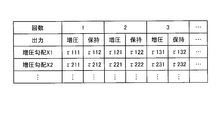
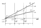
図5は、第1実施形態において所望の増圧勾配を実現するための具体的な手段の例を示した例示的な図であり、図6は、第1実施形態において図5に示された手段により実現される増圧勾配の例を示した例示的なグラフである。
図5および図6に示されるように、第1実施形態では、ホイールシリンダ圧の増圧と、ホイールシリンダ圧の保持と、からなるサイクルが一定の周期Τで複数回繰り返されることで、所望の増圧勾配が実現される。増圧は、増圧弁125aを開状態にする指示(出力)によって実現され、保持は、増圧弁125aを閉状態にする指示(出力)によって実現される。なお、図5および図6では、4回目以降のサイクルの図示を省略している。
図5の例において、τ111およびτ112は、それぞれ、増圧勾配X1を実現するための1回目のサイクルにおける増圧および保持の実行時間を表す。また、τ121およびτ122は、それぞれ、増圧勾配X1を実現するための2回目のサイクルにおける増圧および保持の実行時間を表す。また、τ131およびτ132は、それぞれ、増圧勾配X1を実現するための3回目のサイクルにおける増圧および保持の実行時間を表す。なお、τ111とτ112との和、τ121とτ122との和、およびτ131とτ132との和は、それぞれ等しく、上記の周期Τと一致するものとする。これらのサイクルによれば、図6の例における一点鎖線L10のような、増圧勾配X1を表す実線L11と近似したホイールシリンダ圧の変化を得ることができる。
同様に、図5の例において、τ211およびτ212は、それぞれ、増圧勾配X2を実現するための1回目のサイクルにおける増圧および保持の実行時間を表す。また、τ221およびτ222は、それぞれ、増圧勾配X2を実現するための2回目のサイクルにおける増圧および保持の実行時間を表す。また、τ231およびτ232は、それぞれ、増圧勾配X2を実現するための3回目のサイクルにおける増圧および保持の実行時間を表す。なお、τ211とτ212との和、τ221とτ222との和、およびτ231とτ232との和は、それぞれ等しく、上記の周期Τと一致するものとする。これらのサイクルによれば、図6の例における二点鎖線L20のような、増圧勾配X2を表す実線L21と近似したホイールシリンダ圧の変化を得ることができる。
第1実施形態では、サイクル毎の増圧および保持の実行時間が様々な増圧勾配に応じて設定された図5に示されるような情報が、テーブルやマップなどといった形式で予め記憶されている。これにより、第1実施形態では、第1推定値と第2推定値との偏差に応じた様々な増圧勾配を容易に実現することができる。
次に、第1実施形態において実行される処理の流れについて説明する。
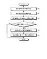
図7は、第1実施形態によるブレーキ制御装置200がアンチロック制御中に実行する処理を示した例示的なフローチャートである。第1実施形態では、図7に示される一連の処理が、アンチロック制御中に繰り返し実行される。
図7に示されるように、ブレーキ制御装置200の算出部202は、まず、S1において、加速度センサ302の出力値のみに基づく第1の手法で、車両10の減速度の第1推定値を算出する。
そして、S2において、算出部202は、加速度センサ302の出力値と、アンチロック制御の制御状態とに基づく第2の手法で、車両10の減速度の第2推定値を算出する。
そして、S3において、制御部203は、S1で算出された第1推定値と、S2で算出された第2推定値と、の偏差を算出する。より具体的に、制御部203は、S2で算出された第2推定値から、S1で算出された第1推定値を減算することで、偏差を求める。この場合、制御部203は、たとえば第2推定値より第1推定値が大きい場合には、偏差を0(ゼロ)としてもよい。
そして、S4において、制御部203は、S3で算出された偏差が閾値を超えたか否かを判断する。
S4において、S3で算出された偏差が閾値以下であると判断された場合、そのまま処理が終了する。しかしながら、S4において、S3で算出された偏差が閾値を超えたと判断された場合、S5に処理が進む。
S5において、制御部203は、S3で算出された偏差に基づき、ホイールシリンダ圧の増圧勾配を補正するための補正係数を算出する。より具体的に、制御部203は、偏差が第1偏差であるときにおける増圧勾配が、偏差が第1偏差よりも小さい第2偏差であるときにおける増圧勾配よりも大きくなるという条件を満たすような補正係数を算出する。
そして、S6において、制御部203は、S5で算出された補正係数に基づいて増圧勾配を補正する。そして、制御部203は、補正された増圧勾配に対応する図5の情報に従って増圧制御(緩増圧制御)を実行し、処理が終了する。
以上のような構成および処理により、第1実施形態では、アンチロック制御とともにポンピングブレーキが行われる場合に、以下のようなタイミングチャートに沿ったブレーキ制御が実現される。以下、第1実施形態によるブレーキ制御を、比較例によるブレーキ制御と対比して説明する。
まず、比較例によるブレーキ制御について簡単に説明する。この比較例は、第1実施形態のような第1推定値と第2推定値との偏差に基づく増圧勾配の補正が実行されない例である。
図8は、比較例によるブレーキ制御を説明するための例示的なタイミングチャートである。図8において、実線L101は、車速(第1実施形態では車両10の速度に対応)の時間変化を表し、実線L102は、車輪速(第1実施形態では前輪2Fの回転速度に対応)の時間変化を表す。
また、実線L103は、マスタシリンダ圧(MC圧、第1実施形態では前輪2F側のマスタシリンダ112の圧力に対応)の推定値の時間変化を表す。また、実線L104は、ホイールシリンダ圧(WC圧、第1実施形態では前輪2F側のホイールシリンダ123の圧力に対応)の推定値の時間変化を表し、一点鎖線L104aは、車輪のロックを引き起こすホイールシリンダ圧であるロック圧P100を表す。
また、点線L105は、車両の走行状態に基づいて算出される減速度(第1実施形態では第1推定値に対応)の時間変化を表し、実線L106は、アンチロック制御の制御状態の時間変化を表す。
図8の例では、タイミングT100で、ポンピングブレーキにおける最初のブレーキ操作が開始されるものとする。そして、タイミングT105で、ポンピングブレーキにおけるブレーキ操作の解除が開始され、タイミングT107で、当該ブレーキ操作が完全に解除されるものとする。そして、タイミングT108で、ポンピングブレーキにおける再度のブレーキ操作が開始されるものとする。
図8に示されるように、比較例では、タイミングT100からタイミングT101にかけて、最初のブレーキ操作に応じてマスタシリンダ圧およびホイールシリンダ圧が上昇し(実線L103およびL104参照)、減速度が大きくなる(点線L105参照)。そして、タイミングT101で、ホイールシリンダ圧がロック圧P100に接近し(一点鎖線L104a参照)、車速と車輪速との乖離が所定値以上となる(実線L101およびL102参照)。この結果、タイミングT101で車輪のロック傾向が見られるようになり、アンチロック制御の制御状態が、制御開始前を表す未制御の状態から、減圧制御に切り替わる(実線L106参照)。
タイミングT101で減圧制御が開始すると、当該減圧制御に伴ってホイールシリンダ圧が低下し(実線L104参照)、タイミングT102で、車輪速の落ち込みが略止まる(実線L102参照)。これにより、ホイールシリンダ圧をさらに低下させる必要はないとの判断が行われ、タイミングT102で、減圧制御が保持制御へと移行する(実線L106参照)。
タイミングT102で保持制御が開始すると、ホイールシリンダ圧がそのまま維持され(実線L104参照)、タイミングT103で、車輪速の回復(上昇)傾向が見られるようになる(実線L102参照)。これにより、タイミングT103では、制動力確保のためにホイールシリンダ圧を上昇させる必要があるとの判断が行われ、減圧制御が急増圧制御へと移行する(実線L106参照)。
タイミングT103で急増圧制御が開始すると、急増圧制御で予め設定された増圧勾配で、ホイールシリンダ圧が上昇する(実線L104参照)。そして、ホイールシリンダ圧の上昇量である増圧量が所定量に達した(あるいは所定時間が経過した)タイミングT104で、急増圧制御が緩増圧制御へと移行する(実線L106参照)。これにより、タイミングT104以降は、緩増圧制御で予め設定された、急増圧制御の増圧勾配よりも緩やかな増圧勾配で、ホイールシリンダ圧が緩やかに上昇する(実線L104参照)。
そして、タイミングT105で、ブレーキ操作の解除が開始される。すると、タイミングT106で、ブレーキ機構(第1実施形態では前輪2F側のブレーキ機構110に対応)の動作が開始し、マスタシリンダ圧が低下する(実線L103参照)。マスタシリンダ圧が低下すると、それに伴い、ホイールシリンダ圧も低下し(実線L104参照)、車両の減速度が小さくなる(点線L105参照)。そして、マスタシリンダ圧、ホイールシリンダ圧、および減速度は、ブレーキ操作が完全に解除されたタイミングT107で、ゼロになる。
そして、タイミングT108で、再度のブレーキ操作が行われる。すると、再びブレーキ機構の動作が開始し、マスタシリンダ圧が上昇する(実線L103参照)。しかしながら、タイミングT108では、緩増圧制御が未だ実行中であるため(実線L106参照)、ホイールシリンダ圧は、ホイールシリンダ圧が再びロック圧P100に接近するタイミングT109までは、ブレーキ操作の量に関わらず、緩増圧制御で予め設定された緩やかな増圧勾配でしか上昇することがない(実線L104参照)。したがって、図8の例では、タイミングT108以降で、ドライバのブレーキ操作と実際に発生する制動力との不整合が発生しうる。なお、これ以降のタイミングT109~T112における動作は、それぞれ、タイミングT101~T104における動作と同様であるため、ここでは説明を省略する。
このように、第1実施形態のような第1推定値と第2推定値との偏差に基づく増圧勾配の補正を実行しない比較例では、アンチロック制御の増圧制御とともにポンピングブレーキが行われた場合(特に、ブレーキ操作の解除後の再度のブレーキ操作が増圧制御とともに行われた場合)に、ドライバのブレーキ操作と実際に発生する制動力との不整合が発生しうる。
これに対して、第1実施形態は、アンチロック制御の増圧制御とともにポンピングブレーキが行われた場合に、第1推定値と第2推定値との偏差に基づく増圧勾配の補正を実行することで、上記の不整合の発生が抑制された以下のようなブレーキ制御を実現する。
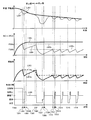
図9は、第1実施形態によるブレーキ制御を説明するための例示的なタイミングチャートである。図9において、実線L201は、車両10の速度(車速)の時間変化を表し、実線L202は、前輪2Fの回転速度(車輪速)の時間変化を表す。
また、実線L203は、前輪2F側のマスタシリンダ112の圧力(マスタシリンダ圧、MC圧)の推定値の時間変化を表す。また、実線L204は、前輪2F側のホイールシリンダ123の圧力(ホイールシリンダ圧、WC圧)の推定値の時間変化を表し、一点鎖線L204aは、前輪2Fのロックを引き起こすホイールシリンダ圧であるロック圧P200を表す。
また、点線L205は、加速度センサ302の出力値のみに基づく第1の方法で算出される車両10の減速度の第1推定値の時間変化を表し、実線L205aは、加速度センサ302の出力値とアンチロック制御の制御状態とに基づく第2の方法で算出される車両10の減速度の第2推定値の時間変化を表す。また、実線L206は、アンチロック制御の制御状態の時間変化を表す。
図9の例では、タイミングT200で、ポンピングブレーキにおけるドライバの最初のブレーキ操作が開始されるものとする。そして、タイミングT205で、ポンピングブレーキにおけるブレーキ操作の解除が開始され、タイミングT209で、当該ブレーキ操作が完全に解除されるものとする。そして、タイミングT210で、ポンピングブレーキにおける再度のブレーキ操作が開始されるものとする。
図9に示されるように、第1実施形態では、タイミングT200からタイミングT201にかけて、最初のブレーキ操作に応じてマスタシリンダ圧およびホイールシリンダ圧が上昇する(実線L203およびL204参照)。これにより、車両10の実際の走行状態に基づく第1推定値と、ホイールシリンダ圧の推定値に基づく第2推定値とは、共に大きくなる(点線L205および実線L205a参照)。
そして、タイミングT201でホイールシリンダ圧がロック圧P200に接近すると(一点鎖線L204a参照)と、車速と車輪速との乖離が所定値以上となり(実線L201およびL202参照)、前輪2Fのロック傾向が見られるようになる。これにより、タイミングT201で、アンチロック制御の制御状態が、制御開始前を表す未制御の状態から、減圧制御に切り替わる(実線L206参照)。
タイミングT201で減圧制御が開始すると、当該減圧制御に伴ってホイールシリンダ圧が低下し(実線L204参照)、タイミングT202で、車輪速の落ち込みが略止まる(実線L202参照)。この間、車両10は、前輪2Fがロックした状態でスリップした状態になっている。したがって、ホイールシリンダ圧が低下したとしても、加速度センサ302の出力値のみから得られる減速度である第1推定値は、略変化しない(点線L205参照)。一方、第2推定値は、ホイールシリンダ圧を減速度に換算することで得られるものである。したがって、ホイールシリンダ圧が低下すると、第2推定値は、当該ホイールシリンダ圧の低下に伴って低下する(実線L205a参照)。そして、タイミングT202で車輪速の落ち込みが略止まると、減圧制御が保持制御へと移行する(実線L206参照)。
タイミングT202で保持制御が開始すると、ホイールシリンダ圧がそのまま維持され(実線L204参照)、タイミングT203で、車輪速の回復(上昇)傾向が見られるようになる(実線L202参照)。この間、第1推定値は、上記と同様に略変化しない(点線L205参照)。また、第2推定値も、ホイールシリンダ圧の保持に伴い、変化しない(実線L205a参照)。タイミングT203で車輪速の回復傾向が見られるようになると、減圧制御が急増圧制御へと移行する(実線L206参照)。
タイミングT203で急増圧制御が開始すると、当該急増圧制御で予め設定された増圧勾配で、ホイールシリンダ圧が上昇する(実線L204参照)。そして、ホイールシリンダ圧の上昇量(増圧量)が所定量に達したタイミングT204で、急増圧制御が緩増圧制御へと移行する(実線L206参照)。これにより、タイミングT204以降は、緩増圧制御で予め設定された、急増圧制御の増圧勾配よりも緩やかな増圧勾配で、ホイールシリンダ圧が緩やかに上昇し(実線L204参照)、車速と車輪速との乖離が徐々に小さくなる(実線L201およびL202参照)。そして、第1推定値は、車速と車輪速との一致によるスリップの解消に伴って徐々に低下する(点線L205参照)。一方、第2推定値は、ホイールシリンダ圧の上昇に対応するように上昇する(実線L205a参照)。
そして、タイミングT205で、ブレーキ操作の解除が開始される。すると、タイミングT206で、前輪2F側のブレーキ機構110の動作が開始し、マスタシリンダ圧が低下する(実線L203参照)。マスタシリンダ圧が低下すると、これに伴い、ホイールシリンダ圧も低下する(実線L204参照)。そして、ホイールシリンダ圧が低下すると、車両10の制動力が低下し、加速度センサ302の出力値のみから得られる減速度である第1推定値も低下する(点線L205参照)。
このように、ブレーキ操作の解除が開始されたタイミングT205以降、第1推定値は低下していく(点線L205参照)。一方、第2推定値は、ブレーキ操作とは関係なく、マスタシリンダ圧が所定値を維持していることを前提としたアンチロック制御の制御状態を反映するので、ブレーキ操作の解除が開始されたタイミングT205以降も、緩増圧制御で予め設定された緩やかな増圧勾配で、緩やかに上昇を続ける(実線L205a参照)。したがって、第1推定値と第2推定値とが交差するタイミングT206以降は、第1推定値と第2推定値との偏差が徐々に広がっていく(点線L205と実線L205aとの間の両向き矢印参照)。
ここで、上述したように、第1実施形態では、第1推定値と第2推定値との偏差が閾値を超えた場合に、当該偏差に応じて、アンチロック制御の増圧制御におけるホイールシリンダ圧の増圧勾配が補正される。増圧勾配は、偏差が大きいほど大きくなるように補正されてもよいし、偏差が閾値を超えた時点から所定の区間における当該偏差の最大値に基づいて補正されてもよいが、以下では、一例として、増圧勾配が前者のように補正される例について説明する。
図9の例では、第1推定値と第2推定値との偏差が閾値を超えたタイミングT207で、増圧制御におけるホイールシリンダ圧の増圧勾配の補正が開始される。これにより、偏差がタイミングT207よりも広がったタイミングT208では、増圧勾配が、タイミングT207の増圧勾配よりも大きい値となる。すなわち、タイミングT207での増圧勾配を第1増圧勾配(通常の緩増圧制御における増圧勾配)とし、タイミングT208での増圧勾配を第2増圧勾配とすると、第2増圧勾配>第1増圧勾配という大小関係が成立する。
そして、タイミングT209でブレーキ操作の完全な解除が行われ、タイミングT210で再度のブレーキ操作が行われると、タイミングT210以降における各種の状態量の時間変化は、次のようになる。
タイミングT210で再度のブレーキ操作が行われると、再び前輪2F側のブレーキ機構110の動作が開始し、マスタシリンダ圧が上昇する(実線L203参照)。このとき、緩増圧制御は、未だ実行中であり(実線L206参照)、かつ、ホイールシリンダ圧の増圧勾配は、上記のように、通常の緩増圧制御における増圧勾配よりも大きい値に設定されている。したがって、このとき、ホイールシリンダ圧は、通常よりも素早く上昇する(実線L204参照)。
なお、タイミングT210以降は、第1推定値と第2推定値との偏差が徐々に小さくなっていく(点線L205と実線L205aとの間の両向き矢印参照)。したがって、ホイールシリンダ圧の増圧勾配は、偏差がある程度小さくなったタイミングT211で、より小さい値に切り替わる(実線L204参照)。
また、タイミングT211以降は、第1推定値と第2推定値との偏差がさらに小さくなっていく(点線L205と実線L205aとの間の両向き矢印参照)。この結果、タイミングT212で偏差がタイミングT207の偏差と同等になると、増圧勾配の補正が終了し、ホイールシリンダ圧が通常の増圧勾配で上昇するようになる(実線L204参照)。この通常の増圧勾配は、ホイールシリンダ圧が再びロック圧P200に接近するタイミングT213までは、そのまま維持される。
なお、タイミングT213~T216における動作は、それぞれ、タイミングT201~204における動作と同様であり、タイミングT217~T220における動作も、それぞれ、タイミングT201~204における動作と同様であるため、ここでは説明を省略する。
このように、第1実施形態では、比較例と異なり、第1推定値と第2推定値との偏差に基づく増圧勾配の補正が実行されることで、アンチロック制御の増圧制御とともにポンピングブレーキ(より具体的にはブレーキ操作の解除後の再度のブレーキ操作)が行われた場合であっても、ドライバのブレーキ操作に応じて素早くホイールシリンダ圧が上昇するため、ドライバのブレーキ操作と実際に発生する制動力との不整合の発生を抑制することができる。
また、第1実施形態は、第1推定値と第2推定値との偏差に基づいて、増圧勾配の補正を実行するか否かを決定している。したがって、第1実施形態による増圧勾配の補正は、増圧勾配を補正する必要が無い次のような状況では実行されることがないので、この点においても有効に機能する。
図10は、第1実施形態によるブレーキ制御の有効性を説明するための例示的なタイミングチャートである。図10において、実線L301は、車両10の速度(車速)の時間変化を表し、実線L302は、前輪2Fの回転速度(車輪速)の時間変化を表す。また、実線L303は、前輪2F側のマスタシリンダ112の圧力(マスタシリンダ圧、MC圧)の推定値の時間変化を表し、実線L304は、前輪2F側のホイールシリンダ123の圧力(ホイールシリンダ圧、WC圧)の推定値の時間変化を表す。
また、図10において、一点鎖線L304aは、路面抵抗が比較的高い路面(高μ路)上で前輪2Fのロックを引き起こすホイールシリンダ圧であるロック圧P300aを表し、二点鎖線L304bは、路面抵抗が比較的低い路面(低μ路)上でのロック圧P300bを表す。また、点線L305は、加速度センサ302の出力値のみに基づく第1の方法で算出される車両10の減速度の第1推定値の時間変化を表し、実線L305aは、加速度センサ302の出力値とアンチロック制御の制御状態とに基づく第2の方法で算出される車両10の減速度の第2推定値の時間変化を表す。また、実線L306は、アンチロック制御の制御状態の時間変化を表す。
図10の例では、タイミングT300で、ポンピングブレーキではない通常のブレーキ操作が開始されるものとする。また、図10の例では、タイミングT305で、車両10の走行路面が高μ路から低μ路に変化するものとする。なお、図10において、タイミングT300~T304の動作は、それぞれ、上述した図9におけるタイミングT200~T204の動作と同様であるので、以下では、タイミングT305以降の動作について説明する。
図10に示されるように、タイミングT305で走行路面が高μ路から低μ路に変化すると、その直後のタイミングT305で、路面抵抗の変化に伴い、車輪速が大きく落ち込み始める(実線L302参照)。したがって、タイミングT306で、アンチロック制御の制御状態は、緩増圧制御から減圧制御に切り替わる(実線L306参照)。
タイミングT306で減圧制御が開始すると、当該減圧制御に伴ってホイールシリンダ圧が低下し(実線L304参照)、タイミングT307で、車輪速の落ち込みが略止まる(実線L302参照)。この間、ホイールシリンダ圧を減速度に換算することで得られる第2推定値は、ホイールシリンダ圧の低下に伴って低下する(実線L305a参照)。ここで、加速度センサ302の出力値のみから得られる減速度である第1推定値は、路面抵抗の変化がなければ、上述した図9の例と同様に略変化しないが、図10の例では、タイミングT305で路面抵抗が小さくなっている。したがって、図10の例では、タイミングT305以降の所定区間において、路面抵抗の低下に応じて第1推定値も所定量低下する(点線L305参照)。
上記の結果、タイミングT306からタイミングT307にかけて第1推定値が低下するとき、第2推定値も大きく低下することになる。したがって、この場合、第1推定値と第2推定値との偏差が閾値以上となることがないので、当該偏差に応じた増圧勾配の補正が開始されることはない。これにより、走行路面が高μ路から低μ路に変化した場合に、通常よりも大きい増圧勾配でホイールシリンダ圧が上昇することがなくなる。この結果、ホイールシリンダ圧が低μ路におけるロック圧P300bに急に接近して車輪速がすぐに落ち込むなど、アンチロック制御の本来の狙いとは外れた制御が実行されるのを回避することができる。
なお、タイミングT307~T309における動作は、ロック圧P300aがロック圧P300bに変化していること以外は、タイミングT302~T304における動作と実質的に同様であるので、ここでは説明を省略する。また、タイミングT310~T313における動作は、それぞれ、タイミングT307~T309における動作と同様であるので、ここでは説明を省略する。また、タイミングT314以降、T315以降、およびT316以降における動作についても、同様に説明を省略する。
このように、第1実施形態によれば、第1推定値と第2推定値との偏差が閾値以上になるか否かを監視することで、走行路面が高μ路から低μ路に変化したことによる車両の減速度の低下をポンピングブレーキだと誤判定するのを回避することができる。これにより、増圧勾配の補正を行う必要が無い状況で増圧勾配の補正が行われるのを回避することができる。
この他にも、たとえば通常ではアンチロック制御に入らないような緩やかな制動中に路面の凹凸(段差)などといったいわゆる路面外乱によってアンチロック制御が開始される状況では、マスタシリンダ圧が低いことによって、想定した増圧勾配でホイールシリンダ圧が増加せず、車両の減速度が低い状態が続くことが想定される。この場合、第1実施形態によれば、所定の増圧勾配で増加することを前提に算出された第2推定値と、車両の減速度を示す第1推定値の偏差が大きくなるため、増圧勾配の補正が行われ、より高い増圧勾配への切り替えが実行される。したがって、この点においても、第1実施形態は有効である。
<第2実施形態>
上述した第1実施形態では、車両10の減速度の第1推定値を、加速度センサ302の出力値のみを用いて算出する例について説明した。しかしながら、第1推定値は、減速度であるため、車輪速から算出される車速から求めることも可能である。そこで、以下では、第2実施形態として、加速度センサ302の出力値ではなく、車輪速センサ301の出力値のみを用いて第1推定値を算出する例について説明する。
上述した第1実施形態では、車両10の減速度の第1推定値を、加速度センサ302の出力値のみを用いて算出する例について説明した。しかしながら、第1推定値は、減速度であるため、車輪速から算出される車速から求めることも可能である。そこで、以下では、第2実施形態として、加速度センサ302の出力値ではなく、車輪速センサ301の出力値のみを用いて第1推定値を算出する例について説明する。
ここで、車輪速=車速とすると、車輪(前輪2F)のロックにより車輪速が落ち込んでも、それに追従して車速も落ち込むことになるので、車輪のスリップが検出できない。したがって、この場合、車速が落ち込む速度(=減速度)に上限値(制限値)を設定する。この制限値は、たとえば、車両10が発生可能な最大の減速度に基づいて設定される。これにより、車輪速が急に大きく落ち込んだ場合でも、車速が落ち込む速度は最大でも上記の制限値となるので、車輪速と車速との乖離を検出し、車輪のスリップを検出することが可能になる。
ところで、第1推定値は、減速度であるため、車輪速センサ301の出力値のみを用いて第1推定値を算出すると、車輪のスリップが解消して車輪速が回復傾向になる場合に、第1推定値が+側(減速側)から-側(加速側)に一気に変動することになる。この場合、第1推定値と第2推定値との偏差も一気に大きくなる。上述した第1実施形態の技術によれば、偏差が一気に大きくなると、ホイールシリンダ圧の増圧勾配も一気に大きくなるが、このような制御を実行すると、ホイールシリンダ圧が急に大きくなり過ぎて車輪速がすぐに落ち込むなど、アンチロック制御の本来の狙いとは外れた制御が実行されるおそれがある。
そこで、第2実施形態では、以下に説明するように、第1推定値と第2推定値との偏差が閾値を超えた場合でも、車輪速の増加とともに第1推定値が増加する場合は、ホイールシリンダ圧の増圧勾配の補正が保留される。
図11は、第2実施形態によるブレーキ制御を説明するための例示的なタイミングチャートである。図11において、実線L401は、車両10の速度(車速)の時間変化を表し、実線L402は、前輪2Fの回転速度(車輪速)の時間変化を表す。
また、実線L403は、前輪2F側のマスタシリンダ112の圧力(マスタシリンダ圧、MC圧)の推定値の時間変化を表す。また、実線L404は、前輪2F側のホイールシリンダ123の圧力(ホイールシリンダ圧、WC圧)の推定値の時間変化を表し、一点鎖線L404aは、前輪2Fのロックを引き起こすホイールシリンダ圧であるロック圧P400を表す。
また、点線L405は、車輪速センサ301の出力値のみを用いて算出される車両10の減速度の第1推定値の時間変化を表し、実線L405aは、加速度センサ302の出力値とアンチロック制御の制御状態とに基づく第2の方法で算出される車両10の減速度の第2推定値の時間変化を表す。また、一点鎖線L405bは、車両10が発生可能な減速度の制限値D400を表す。また、実線L406は、アンチロック制御の制御状態の時間変化を表す。
図11の例では、タイミングT400で、ポンピングブレーキではない通常のブレーキ操作が開始されるものとする。
図11に示されるように、第2実施形態では、タイミングT400からタイミングT401にかけて、ブレーキ操作に応じてマスタシリンダ圧およびホイールシリンダ圧が上昇する(実線L403およびL404参照)。これにより、車両10の実際の走行状態に基づく第1推定値と、ホイールシリンダ圧の推定値に基づく第2推定値とは、共に大きくなる(点線L405および実線L405a参照)。
そして、タイミングT401でホイールシリンダ圧がロック圧P400に接近すると(実線L404および一点鎖線L404a参照)、車輪のロック傾向が見られるようになる。すると、車輪速の落ち込みが始まり(実線L402参照)、それに伴い、車速の落ち込みも始まる(実線L401参照)。
そして、タイミングT402で第1推定値および第2推定値が制限値D400に達すると(点線L405、実線L405a、および一点鎖線L405b参照)、車輪速の落ち込み速度はより大きくなる一方(実線L402参照)、車速の落ち込み速度は略一定となる(実線L401参照)。これにより、タイミングT402以降は、車輪速と車速との乖離が徐々に大きくなっていく。
そして、タイミングT403でホイールシリンダ圧がロック圧P400に到達すると(一点鎖線L404a参照)、車輪速と車速との乖離が所定値以上となり(実線L401およびL402参照)、車輪(前輪2F)のロック傾向が見られるようになる。これにより、タイミングT403で、アンチロック制御の制御状態が、制御開始前を表す未制御の状態から、減圧制御に切り替わる(実線L406参照)。これ以降のタイミングT403~T406までの動作は、それぞれ、上述した図9におけるタイミングT201~T204までの動作と同様であるので、ここでは説明を省略する。
図11の例では、タイミングT406で車輪速と車速とが一致する(実線L401およびL402参照)。つまり、タイミングT406では、車輪のスリップが解消して車輪速が回復傾向になっていると言える。したがって、このとき、車輪速のみを用いて算出される減速度である第1推定値は、+側(減速側)から-側(加速側)に一気に変動する(点線L405参照)。一方、第2推定値は、アンチロック制御の制御状態も考慮したホイールシリンダ圧の推定値に基づいているため、第1推定値のような急激な変動は起こらない。したがって、この場合、第1推定値と第2推定値との偏差が一気に閾値以上まで大きくなる。
ここで、第1実施形態の技術をそのまま適用すると、タイミングT406で、ホイールシリンダ圧の増圧勾配の補正が行われることになる。しかしながら、第1推定値が減速側から加速側に一気に変動することによって生じる偏差は、通常想定される偏差に比べて非常に大きいため、この偏差を反映して増圧勾配を補正すると、ホイールシリンダ圧が急に大きくなり過ぎて車輪速がすぐに落ち込むなど、アンチロック制御の本来の狙いとは外れた制御が実行されることになる。
すなわち、図11の例では、タイミングT406以降で、車輪速の増加とともに第1推定値が増加することで、第1推定値と第2推定値との偏差がすぐに小さくなるので、このような場合にまでホイールシリンダ圧の増圧勾配の補正を行うのは適当ではない。したがって、第2実施形態は、第1推定値と第2推定値との偏差が閾値を超えた場合でも、車輪速の増加とともに第1推定値が増加する場合は、ホイールシリンダ圧の増圧勾配の補正を保留することで、車輪速センサ301の出力値のみを用いて第1推定値を算出する場合において発生しうる上述したような不都合を解消することができる。
なお、タイミングT407~T410における動作は、それぞれ、タイミングT403~T406における動作と同様であるため、ここでは説明を省略する。
以上、本発明のいくつかの実施形態を説明したが、上述した実施形態はあくまで一例であって、発明の範囲を限定することは意図していない。上述した新規な実施形態は、様々な形態で実施されることが可能であり、発明の要旨を逸脱しない範囲で、種々の省略、置き換え、変更を行うことができる。また、上述した実施形態およびその変形は、発明の範囲や要旨に含まれるとともに、請求の範囲に記載された発明とその均等の範囲に含まれる。
Claims (5)
- 車両の車輪に圧力を付与することで制動力を発生させるブレーキ機構を制御するブレーキ制御装置であって、
前記車両の制動中に、前記圧力を減少させる減圧制御と、前記圧力を増加させる増圧制御と、を少なくとも実行することで、前記車輪のロックを抑制するアンチロック制御を実行する制御部と、
前記車両の走行状態に関する情報を検出するセンサの出力値を取得する取得部と、
前記出力値のみに基づく第1の手法で、前記車両に発生している減速度の第1推定値を算出するとともに、前記出力値と、前記アンチロック制御の制御状態と、に基づく第2の手法で、前記減速度の第2推定値を算出する算出部と、
を備え、
前記制御部は、前記増圧制御の実行時に、前記第1推定値と前記第2推定値との偏差が第1偏差であるときにおける前記圧力の増圧勾配が、前記偏差が前記第1偏差よりも小さい第2偏差であるときにおける前記増圧勾配よりも大きくなるように、前記増圧勾配を補正する、
ブレーキ制御装置。 - 前記制御部は、前記偏差が大きいほど前記増圧勾配が大きくなるように前記増圧勾配を補正する、
請求項1に記載のブレーキ制御装置。 - 前記制御部は、所定の区間における前記偏差の最大値に基づいて前記増圧勾配を補正する、
請求項1に記載のブレーキ制御装置。 - 前記制御部は、前記増圧制御の実行時に、前記偏差が閾値を超えた場合に、前記増圧勾配の補正を実行する、
請求項1~3のいずれか1項に記載のブレーキ制御装置。 - 前記センサは、前記車輪の回転速度を検出する車輪速センサを含み、
前記制御部は、前記偏差が前記閾値を超えた場合でも、前記回転速度の増加とともに前記第1推定値が増加する場合は、前記増圧勾配の補正を保留する、
請求項4に記載のブレーキ制御装置。
Priority Applications (1)
| Application Number | Priority Date | Filing Date | Title |
|---|---|---|---|
| CN201880013932.6A CN110337392B (zh) | 2017-03-02 | 2018-03-02 | 制动控制装置 |
Applications Claiming Priority (2)
| Application Number | Priority Date | Filing Date | Title |
|---|---|---|---|
| JP2017039622A JP6711301B2 (ja) | 2017-03-02 | 2017-03-02 | ブレーキ制御装置 |
| JP2017-039622 | 2017-03-02 |
Publications (1)
| Publication Number | Publication Date |
|---|---|
| WO2018159792A1 true WO2018159792A1 (ja) | 2018-09-07 |
Family
ID=63370766
Family Applications (1)
| Application Number | Title | Priority Date | Filing Date |
|---|---|---|---|
| PCT/JP2018/007916 Ceased WO2018159792A1 (ja) | 2017-03-02 | 2018-03-02 | ブレーキ制御装置 |
Country Status (3)
| Country | Link |
|---|---|
| JP (1) | JP6711301B2 (ja) |
| CN (1) | CN110337392B (ja) |
| WO (1) | WO2018159792A1 (ja) |
Cited By (1)
| Publication number | Priority date | Publication date | Assignee | Title |
|---|---|---|---|---|
| CN111645652A (zh) * | 2019-10-24 | 2020-09-11 | 摩登汽车有限公司 | 车辆制动力的计算方法 |
Families Citing this family (3)
| Publication number | Priority date | Publication date | Assignee | Title |
|---|---|---|---|---|
| DE102019133010A1 (de) * | 2019-12-04 | 2021-06-10 | Zf Cv Systems Global Gmbh | Ausfallsicherheitsventileinheit für eine Parkbremsfunktion sowie Parkbremsventilanordnung |
| CN111674498B (zh) * | 2020-08-14 | 2020-11-24 | 成都信息工程大学 | 一种自行车智能abs系统 |
| CN114715095B (zh) * | 2022-04-01 | 2023-03-31 | 东风汽车集团股份有限公司 | 一种防抱死制动的系统及控制方法 |
Citations (5)
| Publication number | Priority date | Publication date | Assignee | Title |
|---|---|---|---|---|
| JPH05294226A (ja) * | 1992-04-23 | 1993-11-09 | Nippondenso Co Ltd | アンチスキッド制御装置 |
| JPH11189139A (ja) * | 1997-12-25 | 1999-07-13 | Aisin Seiki Co Ltd | 車両の制動制御装置 |
| JP2001001881A (ja) * | 1999-06-17 | 2001-01-09 | Aisin Seiki Co Ltd | ブレーキ液圧制御装置 |
| JP2004090899A (ja) * | 2002-09-04 | 2004-03-25 | Advics:Kk | 車両用ブレーキ警報装置 |
| JP2007022404A (ja) * | 2005-07-19 | 2007-02-01 | Advics:Kk | アンチスキッド制御装置 |
Family Cites Families (6)
| Publication number | Priority date | Publication date | Assignee | Title |
|---|---|---|---|---|
| US5884987A (en) * | 1995-07-14 | 1999-03-23 | Nissan Diesel Co., Ltd. | Antilock brake device |
| JP3875607B2 (ja) * | 2002-09-04 | 2007-01-31 | 本田技研工業株式会社 | 駐車ブレーキ警報装置 |
| JP2007196705A (ja) * | 2006-01-23 | 2007-08-09 | Toyota Motor Corp | 車両用制動制御装置 |
| JP5411832B2 (ja) * | 2010-11-12 | 2014-02-12 | トヨタ自動車株式会社 | 車両用制動制御システム |
| CN102658812B (zh) * | 2012-05-08 | 2014-08-13 | 清华大学 | 一种电驱动汽车混合制动相平面防抱死控制方法 |
| CN106218616B (zh) * | 2016-08-02 | 2019-02-05 | 天津英创汇智汽车技术有限公司 | 一种无压力传感器的esc系统及其控制方法 |
-
2017
- 2017-03-02 JP JP2017039622A patent/JP6711301B2/ja active Active
-
2018
- 2018-03-02 CN CN201880013932.6A patent/CN110337392B/zh active Active
- 2018-03-02 WO PCT/JP2018/007916 patent/WO2018159792A1/ja not_active Ceased
Patent Citations (5)
| Publication number | Priority date | Publication date | Assignee | Title |
|---|---|---|---|---|
| JPH05294226A (ja) * | 1992-04-23 | 1993-11-09 | Nippondenso Co Ltd | アンチスキッド制御装置 |
| JPH11189139A (ja) * | 1997-12-25 | 1999-07-13 | Aisin Seiki Co Ltd | 車両の制動制御装置 |
| JP2001001881A (ja) * | 1999-06-17 | 2001-01-09 | Aisin Seiki Co Ltd | ブレーキ液圧制御装置 |
| JP2004090899A (ja) * | 2002-09-04 | 2004-03-25 | Advics:Kk | 車両用ブレーキ警報装置 |
| JP2007022404A (ja) * | 2005-07-19 | 2007-02-01 | Advics:Kk | アンチスキッド制御装置 |
Cited By (1)
| Publication number | Priority date | Publication date | Assignee | Title |
|---|---|---|---|---|
| CN111645652A (zh) * | 2019-10-24 | 2020-09-11 | 摩登汽车有限公司 | 车辆制动力的计算方法 |
Also Published As
| Publication number | Publication date |
|---|---|
| JP2018144559A (ja) | 2018-09-20 |
| CN110337392A (zh) | 2019-10-15 |
| JP6711301B2 (ja) | 2020-06-17 |
| CN110337392B (zh) | 2021-09-24 |
Similar Documents
| Publication | Publication Date | Title |
|---|---|---|
| JP6711301B2 (ja) | ブレーキ制御装置 | |
| JP5569550B2 (ja) | 車両の制動制御装置及び車両の制動制御方法 | |
| KR101659773B1 (ko) | 브레이크 시스템 제어 장치 및 제어 방법 | |
| JP5991696B2 (ja) | 車両用ブレーキ液圧制御装置 | |
| KR102286743B1 (ko) | 차량용 회생제동 시스템 제어 방법 | |
| JP5692533B2 (ja) | 車両の制動制御装置 | |
| KR102379930B1 (ko) | 전자식으로 슬립을 제어할 수 있는 차량 브레이크 시스템 내의 제동력을 증강하기 위한 방법 및 전자식으로 슬립을 제어할 수 있는 차량 브레이크 시스템 | |
| JP6214543B2 (ja) | ブレーキペダル振動抑制機能を有する車両ブレーキシステム及びブレーキペダルの振動を抑制する車両ブレーキシステムを動作させる方法 | |
| JP6531740B2 (ja) | ブレーキ制御装置 | |
| WO2018056392A1 (ja) | ブレーキ制御装置 | |
| KR101619418B1 (ko) | 차량의 제동 장치 및 방법 | |
| JP2007216944A (ja) | 車両用ディスクブレーキ制御装置 | |
| CN106143453B (zh) | 电子驻车制动系统的控制方法及装置 | |
| JP6393600B2 (ja) | バーハンドル車両用ブレーキ制御装置 | |
| JP5783663B2 (ja) | 車両のブレーキシステムの少なくとも1つのホイールブレーキシリンダにブレーキ液を移送するための制御装置および方法 | |
| JP2016088146A (ja) | 車両用ブレーキ制御装置 | |
| JP7392355B2 (ja) | 車両の制動制御装置 | |
| JP6281878B2 (ja) | 車両用ブレーキ液圧制御装置 | |
| JP2021103917A (ja) | 制動制御装置 | |
| JP2015003563A (ja) | 車両用ブレーキ液圧制御装置 | |
| JP6656042B2 (ja) | 車両用ブレーキ液圧制御装置 | |
| JP6387949B2 (ja) | 車両のブレーキ制御装置 | |
| JP2018177109A (ja) | 車線逸脱抑制装置 | |
| JP2010095098A (ja) | 制動制御装置及び制動方法 | |
| JP2017081185A (ja) | 車両用ブレーキシステム |
Legal Events
| Date | Code | Title | Description |
|---|---|---|---|
| 121 | Ep: the epo has been informed by wipo that ep was designated in this application |
Ref document number: 18761906 Country of ref document: EP Kind code of ref document: A1 |
|
| NENP | Non-entry into the national phase |
Ref country code: DE |
|
| 122 | Ep: pct application non-entry in european phase |
Ref document number: 18761906 Country of ref document: EP Kind code of ref document: A1 |