WO2018159748A1 - Fe-Ni系合金薄板の製造方法およびFe-Ni系合金薄板 - Google Patents
Fe-Ni系合金薄板の製造方法およびFe-Ni系合金薄板 Download PDFInfo
- Publication number
- WO2018159748A1 WO2018159748A1 PCT/JP2018/007734 JP2018007734W WO2018159748A1 WO 2018159748 A1 WO2018159748 A1 WO 2018159748A1 JP 2018007734 W JP2018007734 W JP 2018007734W WO 2018159748 A1 WO2018159748 A1 WO 2018159748A1
- Authority
- WO
- WIPO (PCT)
- Prior art keywords
- thin plate
- rolling
- cold rolling
- cold
- width
- Prior art date
- Legal status (The legal status is an assumption and is not a legal conclusion. Google has not performed a legal analysis and makes no representation as to the accuracy of the status listed.)
- Ceased
Links
Images


Classifications
-
- B—PERFORMING OPERATIONS; TRANSPORTING
- B21—MECHANICAL METAL-WORKING WITHOUT ESSENTIALLY REMOVING MATERIAL; PUNCHING METAL
- B21B—ROLLING OF METAL
- B21B1/00—Metal-rolling methods or mills for making semi-finished products of solid or profiled cross-section; Sequence of operations in milling trains; Layout of rolling-mill plant, e.g. grouping of stands; Succession of passes or of sectional pass alternations
- B21B1/40—Metal-rolling methods or mills for making semi-finished products of solid or profiled cross-section; Sequence of operations in milling trains; Layout of rolling-mill plant, e.g. grouping of stands; Succession of passes or of sectional pass alternations for rolling foils which present special problems, e.g. because of thinness
-
- B—PERFORMING OPERATIONS; TRANSPORTING
- B21—MECHANICAL METAL-WORKING WITHOUT ESSENTIALLY REMOVING MATERIAL; PUNCHING METAL
- B21B—ROLLING OF METAL
- B21B1/00—Metal-rolling methods or mills for making semi-finished products of solid or profiled cross-section; Sequence of operations in milling trains; Layout of rolling-mill plant, e.g. grouping of stands; Succession of passes or of sectional pass alternations
- B21B1/22—Metal-rolling methods or mills for making semi-finished products of solid or profiled cross-section; Sequence of operations in milling trains; Layout of rolling-mill plant, e.g. grouping of stands; Succession of passes or of sectional pass alternations for rolling plates, strips, bands or sheets of indefinite length
-
- B—PERFORMING OPERATIONS; TRANSPORTING
- B21—MECHANICAL METAL-WORKING WITHOUT ESSENTIALLY REMOVING MATERIAL; PUNCHING METAL
- B21B—ROLLING OF METAL
- B21B15/00—Arrangements for performing additional metal-working operations specially combined with or arranged in, or specially adapted for use in connection with, metal-rolling mills
-
- B—PERFORMING OPERATIONS; TRANSPORTING
- B21—MECHANICAL METAL-WORKING WITHOUT ESSENTIALLY REMOVING MATERIAL; PUNCHING METAL
- B21B—ROLLING OF METAL
- B21B3/00—Rolling materials of special alloys so far as the composition of the alloy requires or permits special rolling methods or sequences ; Rolling of aluminium, copper, zinc or other non-ferrous metals
- B21B3/02—Rolling special iron alloys, e.g. stainless steel
-
- C—CHEMISTRY; METALLURGY
- C21—METALLURGY OF IRON
- C21D—MODIFYING THE PHYSICAL STRUCTURE OF FERROUS METALS; GENERAL DEVICES FOR HEAT TREATMENT OF FERROUS OR NON-FERROUS METALS OR ALLOYS; MAKING METAL MALLEABLE, e.g. BY DECARBURISATION OR TEMPERING
- C21D7/00—Modifying the physical properties of iron or steel by deformation
- C21D7/02—Modifying the physical properties of iron or steel by deformation by cold working
-
- C—CHEMISTRY; METALLURGY
- C21—METALLURGY OF IRON
- C21D—MODIFYING THE PHYSICAL STRUCTURE OF FERROUS METALS; GENERAL DEVICES FOR HEAT TREATMENT OF FERROUS OR NON-FERROUS METALS OR ALLOYS; MAKING METAL MALLEABLE, e.g. BY DECARBURISATION OR TEMPERING
- C21D9/00—Heat treatment, e.g. annealing, hardening, quenching or tempering, adapted for particular articles; Furnaces therefor
- C21D9/46—Heat treatment, e.g. annealing, hardening, quenching or tempering, adapted for particular articles; Furnaces therefor for sheet metals
-
- C—CHEMISTRY; METALLURGY
- C22—METALLURGY; FERROUS OR NON-FERROUS ALLOYS; TREATMENT OF ALLOYS OR NON-FERROUS METALS
- C22C—ALLOYS
- C22C38/00—Ferrous alloys, e.g. steel alloys
-
- C—CHEMISTRY; METALLURGY
- C22—METALLURGY; FERROUS OR NON-FERROUS ALLOYS; TREATMENT OF ALLOYS OR NON-FERROUS METALS
- C22C—ALLOYS
- C22C38/00—Ferrous alloys, e.g. steel alloys
- C22C38/08—Ferrous alloys, e.g. steel alloys containing nickel
-
- C—CHEMISTRY; METALLURGY
- C22—METALLURGY; FERROUS OR NON-FERROUS ALLOYS; TREATMENT OF ALLOYS OR NON-FERROUS METALS
- C22C—ALLOYS
- C22C38/00—Ferrous alloys, e.g. steel alloys
- C22C38/10—Ferrous alloys, e.g. steel alloys containing cobalt
-
- B—PERFORMING OPERATIONS; TRANSPORTING
- B21—MECHANICAL METAL-WORKING WITHOUT ESSENTIALLY REMOVING MATERIAL; PUNCHING METAL
- B21B—ROLLING OF METAL
- B21B15/00—Arrangements for performing additional metal-working operations specially combined with or arranged in, or specially adapted for use in connection with, metal-rolling mills
- B21B2015/0071—Levelling the rolled product
Definitions
- the present invention relates to an Fe—Ni-based alloy thin plate used for, for example, a lead frame or a metal mask, and a method for manufacturing the same.
- ear waves formed at both ends of a thin plate in the direction perpendicular to the rolling direction (hereinafter also referred to as the width direction).
- the ear wave is a wave shape generated at both ends in the width direction of the thin plate, and is formed when the length in the rolling direction of the end portion of the thin plate is longer than the length in the rolling direction of the central portion of the thin plate. Excessive ear waves cause problems such as bending of the plate and meandering when the thin plate is wound, and lowering the adhesion between the thin plate and the film when the film is bonded to the thin plate.
- Patent Document 2 discloses a roll using a work roll for rolling, which has microscopic regular irregularities and a macroscopic pattern constituted by the irregularities is different in the axial direction of the roll. It describes a cold rolling method for suppressing the generation of ear waves by cross rolling.
- Patent Document 1 is useful as a method for suppressing an ear wave, since the roll pressing force at the central portion in the width direction of the thin plate is increased by reducing the roll pressing force at the side end portion, the middle elongation There is a high possibility that another shape defect such as (a wave shape formed at the center in the width direction of the thin plate) will occur.
- Patent Document 2 is also an invention that can reduce the steepness of the ear waves at both ends, but it is necessary to change the tolerance angle and the type of roll depending on the material and shape of the shape, so that productivity is increased. Tend to decrease. In addition, there is no description regarding reducing the length of the acoustic wave in the width direction.
- An object of the present invention is to provide an Fe—Ni-based alloy thin plate that can obtain good flatness with a small amount of trimming and a method for manufacturing the same by controlling the formation range of ear waves.
- One aspect of the present invention is an intermediate cold rolling process for producing an intermediate cold rolled material having a thickness of 0.4 mm or less by performing cold rolling on a material for cold rolling using an Fe—Ni alloy hot rolled material.
- a finish cold rolling step in which the intermediate cold-rolled material is cold-rolled to form a thin plate having a thickness of 0.2 mm or less; Including a shape correction step of performing shape correction on the thin plate,
- a multi-stage rolling mill having an intermediate roll shift mechanism is used to adjust the intermediate roll shift amount, which is a parallel distance between the intermediate roll end and the intermediate cold rolled material end, to 0 to +9 mm.
- the shape correction step the shape correction with an elongation of 0.3 to 0.7 is performed.
- the cold rolling rate in the finish cold rolling step is 15 to 50%.
- the plate width of the thin plate is 500 to 1200 mm.
- Another aspect of the present invention is an Fe—Ni alloy thin plate having a thickness of 0.2 mm or less, At both ends of the thin plate in the direction perpendicular to the rolling direction, there is an ear wave whose maximum length in the direction perpendicular to the rolling direction is within 10% of the width of the thin plate,
- Each of the ear waves is a Fe—Ni-based alloy thin plate in which 10 or more pieces are formed at both ends of the thin plate in the direction perpendicular to the rolling direction, about 800 mm in the rolling direction length of the thin plate.
- the number of ear waves having a maximum width exceeding 10% of the sheet width is 3 or less per 800 mm at both ends of the sheet in the direction perpendicular to the rolling direction.
- the plate width of the thin plate is 500 to 1200 mm.
- the present invention it is possible to suppress the generation of excessive ear waves, middle elongation, and the like by intentionally forming minute ear waves at both ends of the thin plate. As a result, an Fe—Ni alloy thin plate having good flatness can be obtained with a small amount of trimming.
- FIG. 6 is a schematic top view for explaining the shape of a comparative Fe—Ni alloy thin plate. It is the schematic of the finishing mill used in this embodiment. 6 is a graph showing the steepness of thin plates of Invention Example 1 and Comparative Example 11. It is a graph showing the steepness of the thin plates of Invention Example 2 and Comparative Examples 12 and 13.
- an Fe—Ni alloy thin plate having low thermal expansion can be obtained.
- Ni and Co are preferably adjusted to a range of 35.0 to 43.0% in order to obtain low thermal expansion.
- Co does not necessarily need to be added, but Co has the effect of increasing the strength of the Fe—Ni-based alloy. In the range, a part of Ni can be replaced by Co.
- Si and Mn are usually contained in trace amounts in the Fe—Ni alloy for the purpose of deoxidation, but if excessively contained, segregation is likely to occur, so Si is 0.5% or less, and Mn is 1.0%. % Or less is preferable.
- the minimum of Si and Mn is not specifically limited, Since it adds as a deoxidation element as mentioned above, 0.05% of Si and 0.05% of Mn remain not a little.
- the balance is Fe and impurities] Any element other than the above elements may be substantially Fe, but impurities inevitable in production are included. Impurity elements that need to be particularly restricted include C.
- the upper limit is preferably set to 0.05%.
- a free-cutting element such as S may be contained at 0.020% or less.
- An element such as B that improves hot workability may be contained in an amount of 0.0050% or less.
- Cold rolling material In this invention, it can be set as the raw material for cold rolling using the above-mentioned hot rolling material. Since an oxide layer is formed on the hot-rolled material, the oxide layer may be removed, for example, mechanically or chemically. Further, the edge may be trimmed so that a defect such as a crack does not occur from the edge of the cold rolled material during the cold rolling. Such processing can be performed to obtain a material for cold rolling.
- the cold rolling material is cold rolled to produce an intermediate cold rolled material having a thickness of 0.4 mm or less.
- the thickness of the intermediate cold-rolled material exceeds 0.4 mm, the reduction ratio of finish cold rolling described later becomes too high, and a large amount of excessive ear waves and medium elongation tend to occur in the thin plate after finish cold rolling. It is in.
- cold rolling can be performed one or more times, and the rolling reduction can be appropriately set according to the purpose.
- the rolling reduction is 85% or more and the cold rolling is performed only once.
- the upper limit of the rolling reduction is not particularly defined, but if the rolling reduction exceeds 99%, there is a possibility of increasing the cost due to excessive rolling time, so the upper limit can be set to 99%.
- the thickness of the hot-rolled material mentioned above shall be 2 mm or more. If the hot-rolled material is too thick, the number of passes during the cold-rolling process may increase, and it may be difficult to adjust the shape of the Fe-Ni alloy during rolling.
- the upper limit of the thickness is preferably 5 mm.
- softening annealing may be performed in order to remove and soften the strain of the intermediate cold-rolled material work-hardened by the above-described intermediate cold rolling. Thereby, it exists in the tendency which becomes easy to adjust to desired plate
- softening annealing may be performed during the cold rolling. In this embodiment, it is preferable to perform softening annealing at a temperature of 800 ° C. or higher in order to adjust the shape of the crystal grains of the thin plate. Further, if the temperature is too high, desired characteristics may not be obtained, so it is preferable to set the upper limit to 1100 ° C.
- This soft annealing can be performed by continuously passing the intermediate cold-rolled material through a heating furnace set to a desired temperature.
- a heating furnace set to a desired temperature.
- it can be performed by a method in which the intermediate cold-rolled material is drawn out from a rolled state, passed through a heating furnace, and wound into a coil shape.
- finish cold rolling is performed on the intermediate cold-rolled material after the intermediate cold rolling step described above or after the softening annealing described above.
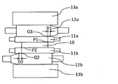
- the rolling mill used in the finish cold rolling process a multi-stage rolling mill having an intermediate roll shift mechanism as shown in FIG. 3 is used, and the intermediate roll shift amount is adjusted to be 0 to +9 mm.
- the load is concentrated on the end portion of the thin plate, and an ear wave (hereinafter also referred to as a micro ear wave) whose maximum width direction length is 10% or less of the thin plate width is referred to as the thin plate end portion. Can be intentionally concentrated.
- the intermediate roll shift amount in the present embodiment means the distances D1 and D2 between the end portions (tapered ends) Q1 and Q2 of the intermediate roll and the end portions P1 and P2 of the intermediate cold rolled material as shown in FIG.
- the intermediate roll shift amount is “+”, it indicates that the taper ends Q1 and Q2 of the intermediate roll are located on the outer side in the roll axis direction from the thin plate ends P1 and P2, and the intermediate roll shift amount is “ ⁇ ”. ”, The taper ends Q1 and Q2 of the intermediate roll are located on the inner side in the roll axis direction than the thin plate ends P1 and P2 (Q1 is located on the left side in FIG. 3 with respect to P1, or Q2 is located in the right direction in FIG. 3 rather than P2.
- the rolling forward tension during finish cold rolling is 20 to 40 kgf / mm 2 and the rolling load to 80 to 120 ton.
- the above-described minute ear waves tend to be more easily formed.
- shape defects such as excessive ear waves are likely to occur, which is not preferable.
- the reduction ratio during finish cold rolling can be set to 50% or less. If it exceeds 50%, a large load is likely to be applied to the central portion in the width direction of the thin plate, so that a medium elongation defect tends to occur.
- the upper limit of the preferable rolling reduction is 45%, more preferably 40%.
- the lower limit of the rolling reduction is not particularly limited, but if the rolling reduction is too small, a desired minute ear wave may not be formed, and can be set to 15%. A preferable lower limit of the rolling reduction is 20%.
- the finish cold rolling is preferably performed in one pass in order to perform rolling at a low cost while suppressing surface defects on the thin plate.
- the thickness after finish cold rolling is 0.2 mm or less. Preferably, it is 0.15 mm or less.
- the lower limit is not particularly limited, it can be set to 0.02 mm because the shape tends to easily change if the material is too thin.
- the Fe—Ni alloy thin plate of the present invention is preferably applied to a wide thin plate, and specifically, the plate width is preferably 500 to 1200 mm. A more preferable lower limit of the plate width is 600 mm, and a more preferable lower limit of the plate width is 700 mm.
- the upper limit of a preferable board width is 1100 mm, More preferably, it is 1000 mm.
- shape correction is performed on a thin plate that has been subjected to finish cold rolling. As a result, it is possible to correct the ear waves and the middle elongation remaining on the thin plate and to greatly improve the flatness.
- a conventionally used shape correction device such as a roller leveler or a tension leveler can be used (in this embodiment, a tension leveler is used).
- the elongation is set to 0.3 to 0.7. When the elongation rate exceeds 0.7, new middle elongation and ear waves may occur in the thin plate, which is not preferable.
- the Fe—Ni thin sheet obtained by the manufacturing method of this embodiment can be wound into a coil by a winder to form a thin coil, which can be supplied to the next step.
- the thin plate obtained by the manufacturing method of the present embodiment can suppress the occurrence of excessive ear waves and medium elongation, and has good flatness, so that it can be used without trimming for cost reduction. It is. However, when it is desired to further improve the flatness, it is preferable to trim both ends in the width direction of the thin plate after the shape correction. Since the thin plate obtained by the manufacturing method of the present embodiment can remove most of the minute ear waves with fewer trimmings than in the past, it is possible to obtain a thin plate with very high flatness (low steepness). For example, in this embodiment, by trimming both ends of the thin plate after shape correction by 1 to 9% of the thin plate width, the maximum steepness is 0.5% or less while suppressing the trimming amount and suppressing the yield reduction.
- a more preferable lower limit of the trimming amount is 4%.
- trimming is performed on both ends of the thin plate by 10 to 20% (more preferably 10 to 16%) of the thin plate width. Thereby, it becomes possible to make the maximum steepness of the thin plate obtained 0.3% or less.
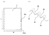
- FIG. 1 shows the wave shape of a thin plate according to an embodiment of the present invention.
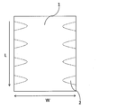
- FIG. 2 shows a schematic diagram of the thin plate of the present invention of the comparative example (assuming that the length L in the rolling direction is 800 mm).
- the Fe—Ni alloy thin plate (before trimming) of the present invention produced by the above-described manufacturing method has a maximum length Wm of 10% or less of the thin plate width W at both ends in the direction perpendicular to the rolling direction (width direction) of the thin plate.
- the ear waves 2 are formed, and ten or more micro ear waves in a length of 800 mm in the rolling direction of the thin plate are formed at both ends of the thin plate.
- an ear wave microwave ear wave
- an ear wave having a short maximum width in the width direction is intentionally formed in a narrow region at the end of the thin plate, so that the maximum length in the width direction exceeds 10% of the thin plate width. Generation of waves (excessive ear waves) and medium elongation can be suppressed.
- the preferred widthwise maximum length Wm of the ear waves is 8% or less of the thin plate width.
- Wm widthwise maximum length
- both ends of the thin plate must be greatly trimmed to remove the ear waves, leading to a decrease in yield.
- the maximum length in the width direction of the micro-ear wave is smaller, it is difficult to manufacture at 0%, so 1% of the thin plate width may be set as the lower limit.
- the maximum lift height of the minute ear wave according to the present embodiment is too large, the maximum length in the width direction of the ear wave tends to increase, and therefore it is preferably 1.0 mm or less.
- a more preferable height is 0.7 mm or less. The smaller the value of the lift height, the better.
- the lower limit may be set to 0.01 mm.
- Such a floating height can be measured by placing a sample on a horizontal surface plate and using a laser displacement meter (three-dimensional shape measuring machine) device or the like.
- the number of micro-ear waves in the present embodiment needs to be 10 or more at both ends in the width direction in a thin plate having a length of 800 mm.
- the number of micro ear waves is less than 10, an excessive ear wave whose maximum length in the width direction of the ear wave exceeds 10% of the thin plate width is likely to be generated.
- the preferred lower limit of the number of minute ear waves can be twelve.
- the upper limit of the number is not particularly set, but considering the ease of manufacturing, the upper limit of the number of ear waves can be set to 30.
- the number of ear waves in the present embodiment can be measured using, for example, a laser displacement meter (three-dimensional shape measuring machine) device by cutting a thin plate into a length of 800 mm and placing it on a horizontal surface plate. it can.
- the number of the ear waves 2a is measured by using a portion that is convex toward the upper surface of the thin plate and has a height of 0.2 mm or more as an ear wave.
- the ear wave 2b having a convex shape toward the lower surface of the thin plate is not measured).
- the ear waves may be measured visually using an existing measuring device such as an optical microscope.
- the width direction maximum length indicates the ear wave maximum length Wm in the direction perpendicular to the plate width from the end of the thin plate.
- the portion indicated by the dotted line in FIG. 1A is a portion having a lift of 0.2 mm or more at both ends of the thin plate, and the length in the width direction is the maximum length of the ear wave Wm.
- the Fe—Ni alloy having the composition shown in Table 1 was hot pressed and hot rolled to prepare a hot rolled material having a thickness of 3.0 mm. Thickness is obtained by removing the oxide layer on the surface of the hot-rolled material by chemical polishing and mechanical polishing of the hot-rolled material described above, and removing cracks at the time of hot rolling at both ends in the width direction of the material by trimming. A material for cold rolling of .55 mm was prepared. In addition, the width
- the material for cold rolling described above was divided into an example of the present invention and a comparative example, and subjected to intermediate cold rolling, soft annealing, and finish cold rolling to obtain a Fe—Ni alloy thin sheet.
- an intermediate cold rolled material having a reduction rate of 85%, a pass number of 10 passes, and a thickness of 0.125 mm was produced using the cold rolling material described above.
- softening annealing was performed at a temperature of 900 ° C. and a holding time of 0.36 minutes to prepare samples of the inventive examples and the comparative examples.
- the intermediate roll shift amount was set to +10 mm, and the rolling forward tension and rolling load were the same as those in Example 2 of the present invention.
- the rolling reduction during finish cold rolling was 36% for both the inventive example and the comparative example, the number of passes was 1 pass, and a thin plate having a thickness of 0.08 mm was used.
- shape correction was performed with a tension leveler under conditions of an elongation of 0.6 and a tension (unit tension) of 60 kgf / mm 2 . No heat treatment was performed after finish cold rolling.
- the thin plate after shape correction is cut into a length of 800 mm with the length direction taken as the rolling direction to produce a test piece having a length of 800 mm, a width of 850 mm or 730 mm, and a thickness of 0.08 mm.
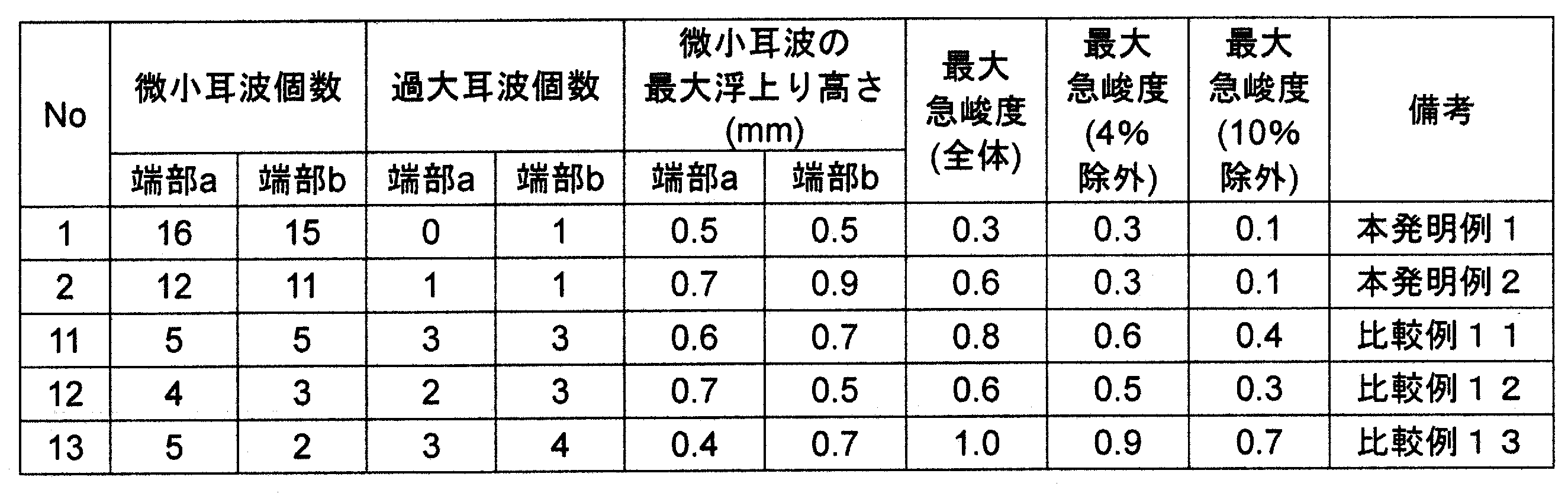
- the number of maximum length in the direction was within 10% of the width of the thin plate, the number of excessive ear waves (the maximum length in the width direction exceeded 10% of the width of the thin plate), and the maximum steepness were measured.
- the number of ear waves at this time was measured with a three-dimensional shape measuring instrument, and the steepness was also derived from the floating height of the test piece placed on a horizontal surface plate using the three-dimensional shape measuring instrument. The results are shown in Table 2.
- the maximum steepness (total) is the maximum value of the steepness of the entire thin plate, and the maximum steepness (excluded by 4%) and the maximum steepness (excluded by 10%) respectively from the end of the thin plate to the thin plate.
- the maximum steepness value excluding the steepness up to the position of 4% of the width and the maximum steepness value excluding the steepness from the end of the thin plate to the position of 10% of the thin plate width are shown.
- the sample No. of the present invention As shown in Table 2 (in Table 2, the one end side is the end portion a and the other end side is the end portion b), the sample No. of the present invention.
- No. 1 has about 15 ear waves (micro ear waves) each having a length in the width direction of 85 mm (10% of the thin plate width) or less at both ends.
- No. 2 confirmed that about 11 ear waves (micro ear waves) having a length in the width direction of 73 mm (10% of the width of the thin plate) or less were formed at both ends.
- An excessive ear wave whose maximum length in the width direction exceeds 10% of the width of the thin plate is also known as Sample No. 1, only one was confirmed on the end b side. In 2, only one was confirmed at each end. The maximum steepness at the edge is no.
- the maximum steepness was a value worse than that of the example of the present invention.
- the comparative example 11 is about 200 mm
- the comparative example 12 is about 120 mm
- the comparative example 13 is about 230 mm at both ends. It can be confirmed that it is necessary to trim. For this reason, there is a concern that the yield of the sample of the comparative example is greatly reduced. From the above, according to the present invention, a very good flatness can be imparted to a thin Fe—Ni alloy thin plate having a thickness of 0.2 mm or less even when the width is increased. Therefore, it has good adhesion and etching properties and can be applied to various uses.
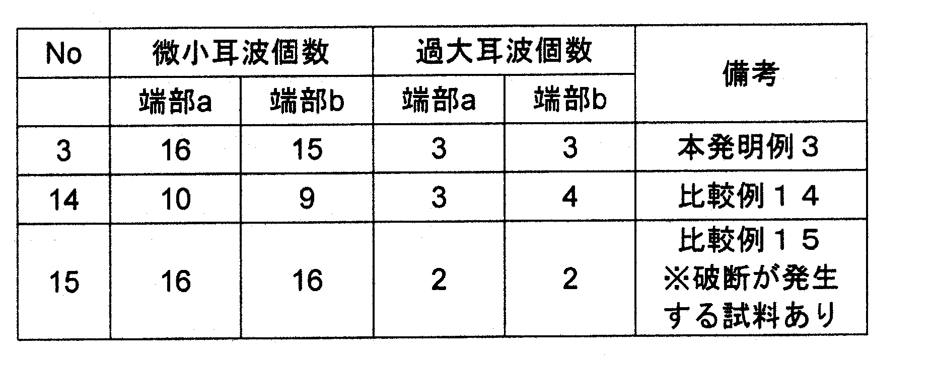
- the tension leveler conditions in shape correction were changed and the effect was confirmed.
- a cold rolling material having a width of 730 mm was prepared, and an Fe—Ni alloy thin sheet was produced under the same conditions as in Example 2 of the present invention until Example cold rolling.
- the elongation condition was changed to the sample after finish cold rolling, and the sample of the present invention and the sample of the comparative example were produced.
- the sample of Invention Example 3 had an elongation of 0.5
- the sample of Comparative Example 14 had an elongation of 0.2
- the sample of Comparative Example 15 had an elongation of 0.8.
- shape correction was performed under the condition of 60 kgf / mm 2 in both the present invention and the comparative example. As in Example 1, no heat treatment was performed after finish cold rolling.
- Comparative Example 14 had a small number of minute ear waves, and the steepness was higher than that of the present invention.
- Comparative Example 15 although the number of micro-ear waves and the steepness were about the same, an uneven shape was generated in the central portion in the width direction of the sample, resulting in an inferior shape as compared with the present invention.
- the elongation rate was too high in the shape correction conditions of Comparative Example 15, it was also confirmed that there was a sample that broke when a plurality of samples were straightened under the same conditions.
Landscapes
- Chemical & Material Sciences (AREA)
- Engineering & Computer Science (AREA)
- Mechanical Engineering (AREA)
- Materials Engineering (AREA)
- Metallurgy (AREA)
- Organic Chemistry (AREA)
- Crystallography & Structural Chemistry (AREA)
- Physics & Mathematics (AREA)
- Thermal Sciences (AREA)
- Metal Rolling (AREA)
- Control Of Metal Rolling (AREA)
Abstract
Description
本発明の目的は、耳波の形成範囲を制御することで、少ないトリミング量で良好な平坦度を得ることができるFe-Ni系合金薄板およびその製造方法を提供することである。
前記中間冷延素材を冷間圧延して厚さ0.2mm以下の薄板とする仕上冷間圧延工程と、
前記薄板に形状矯正を行う形状矯正工程とを含み、
前記仕上冷間圧延工程では、中間ロールシフト機構を有する多段圧延機を用い、中間ロール端部と中間冷延素材端部との間の平行距離である中間ロールシフト量を0~+9mmに調整して冷間圧延が行われ、
前記形状矯正工程では、伸び率0.3~0.7の形状矯正が行われることを特徴とする、Fe-Ni系合金薄板の製造方法である。
好ましくは、仕上冷間圧延工程での冷間圧延率は、15~50%である。
好ましくは、前記薄板の板幅が500~1200mmである。
前記薄板の圧延直角方向両端部には、前記圧延直角方向の最大長さが前記薄板幅の10%以内である耳波を有し、
前記耳波が、前記薄板の圧延方向長さ800mmあたりで、薄板の圧延直角方向両端部にそれぞれ10個以上形成されているFe-Ni系合金薄板である。
好ましくは、薄板幅の10%を超える最大幅を有する耳波が、薄板の圧延直角方向両端部に800mmあたりそれぞれ3個以下である。
好ましくは、前記薄板の板幅が500~1200mmである。
<熱間圧延材組成>
本実施形態では、例えば、質量%でNi+Co:35.0~43.0%(但し、Coは0~6.0%)、Si:0.5%以下、Mn:1.0%以下、残部はFe及び不純物からなる組成を有する熱間圧延材に適用することができる。上記の組成を有することで、低熱膨張性を有するFe-Ni系合金薄板を得ることができる。
[Ni+Co:35.0~43.0%(但し、Coは0~6.0%)]
Ni及びCoは、低熱膨張性を得るために35.0~43.0%の範囲に調整することが好ましい。なお、Coは必ずしも添加の必要はないが、CoにはFe-Ni系合金を高強度とする作用があるため、特に厳しいハンドリング性を求められるような、薄い板厚では6.0%までの範囲で、Niの一部をCoで置換することができる。
Si、Mnは通常Fe-Ni系合金では、脱酸を目的に微量含有されているが、過剰に含有すれば偏析を起こし易くなるため、Siは0.5%以下とし、Mnは1.0%以下とすることが好ましい。なお、SiとMnの下限は特に限定しないが、前述のように脱酸元素として添加されることから、Siは0.05%、Mnは0.05%は少なからず残留する。
[残部はFe及び不純物]
上記の元素以外は実質的にFeであれば良いが、製造上不可避的な不純物は含まれる。特に制限の必要な不純物元素にはCがあり、例えば、エッチングを行う用途に使用するのであれば、その上限を0.05%とすると良い。
また、プレス打抜き性を向上させる場合はS等の快削性元素を0.020%以下で含有させても良い。熱間加工性を向上させるようなB等の元素を0.0050%以下で含有させても良い。
本発明では、前述の熱間圧延材を用いて冷間圧延用素材とすることができる。熱間圧延材には酸化層が形成されていることから、その酸化層を、例えば、機械的、或いは化学的に除去することがよい。また、冷間圧延中の冷間圧延材のエッジから割れ等の不良が発生しないように、エッジをトリミングしてもよい。このような加工を行って冷間圧延用素材とすることができる。
<中間冷間圧延>
本実施形態における中間冷間圧延工程では、冷間圧延用素材に冷間圧延を施して厚さ0.4mm以下の中間冷延素材を作製する。この中間冷延素材の厚さが0.4mmを超える場合、後述する仕上冷間圧延の圧下率が高くなりすぎ、仕上冷間圧延後の薄板に過大な耳波や中伸びが多く発生する傾向にある。この中間冷間圧延工程では、冷間圧延を1回以上行うことができ、圧下率も目的に合わせて適宜設定することができる。より低コストかつ機械特性を向上させるためには、圧下率を85%以上として1回のみ冷間圧延を行う中間冷間圧延工程とすることが好ましい。圧下率の上限は特に定めないが、圧下率が99%を超えると過大な圧延時間によるコストの増大を招く可能性があるため、99%に上限を設定することができる。なお圧下率を85%以上に設定する場合は、上述した熱間圧延材の厚さを2mm以上とすることが好ましい。また熱間圧延材が厚すぎると冷間圧延工程中のパス回数が増えたり、圧延中のFe-Ni系合金の形状の調整が困難になる可能性があるため、用いる熱間圧延材の厚さの上限を5mmとすることが好ましい。
本実施形態では、前述した中間冷間圧延で加工硬化した中間冷延素材の歪を除去して軟化させるために、軟化焼鈍を行ってもよい。これにより、後述する仕上冷間圧延において所望の板厚に調整し易くなる傾向にある。中間冷間圧延工程にて複数回の冷間圧延を行う場合は、その冷間圧延の間に軟化焼鈍を行ってもよい。本実施形態では、薄板の結晶粒の形状を整えるために800℃以上の温度で軟化焼鈍を行うことが好ましい。また温度が高すぎると所望の特性が得られなくなる可能性があるため、上限を1100℃に設定することが好ましい。なおこの軟化焼鈍は、所望の温度に設定された加熱炉に中間冷延素材を連続的に通して行うことができる。例えば、中間冷延素材がロール状に巻かれた状態から引き出し、加熱炉に通板させ、コイル状に巻き取る方法で行うことができる。
本実施形態の製造方法では、前述した中間冷間圧延工程の後、または前述した軟化焼鈍の後の中間冷延素材に仕上冷間圧延を施す。この仕上冷間圧延工程の際に使用する圧延機には、図3に示すような中間ロールシフト機構を有する多段圧延機を用い、中間ロールシフト量が0~+9mmとなるように調整する。このように調整することで、薄板の端部に荷重を集中させ、最大幅方向長さが前記薄板幅の10%以下である耳波(以下、微小耳波とも記載する。)を薄板端部に意図的に集中して形成させることが可能である。この中間ロールシフト量が0mm未満(負値)の場合、薄板に形成される耳波の幅方向長さが過大となったり、幅方向中央部に波形状(中伸び)が発生する傾向にあるため、好ましくない。中間ロールシフト量が+9mmを超える場合、薄板の端部にかかる荷重が大きくなりすぎるため、極端な端部板厚の減少や、端部割れの原因となる傾向にある。より好ましい中間ロールシフト量の上限は、+6mmである。なお本実施形態での中間ロールシフト量とは、図3に示すように中間ロールの端部(テーパー端部)Q1、Q2と中間冷延素材の端部P1、P2との距離D1、D2を示す。中間ロールシフト量が「+」の場合、中間ロールのテーパ端部Q1、Q2が薄板の端部P1、P2よりもロール軸方向外側に位置していることを示し、中間ロールシフト量が「-」の場合、中間ロールのテーパ端部Q1、Q2が薄板の端部P1、P2よりもロール軸方向内側に位置している(Q1がP1よりも図3における左方向に位置している、またはQ2がP2よりも図3における右方向に位置している)ことを示す。
本実施形態の製造方法では、仕上冷間圧延を終えた薄板に形状矯正を行う。これにより薄板に残存している耳波や中伸びを矯正し、平坦度を大幅に向上させることが可能となる。この形状矯正に用いる装置は、ローラレベラーやテンションレベラー等、従来から用いられている形状矯正装置を使用することができる(本実施形態ではテンションレベラーを使用する)。ここで形状矯正は、伸び率を0.3~0.7に設定する。伸び率が0.7を超える場合、新たな中伸びや耳波は薄板に発生する可能性があるため、好ましくない。また伸び率が0.3未満となる場合、波形状を矯正しきれない可能性があるため、好ましくない。好ましい伸び率の下限は0.4であり、好ましい伸び率の上限は0.6である。本実施形態の製造方法で得られたFe-Ni系薄板は、巻取り機によってコイル状に巻きとって薄板コイルとし、次工程に供給することができる。

以上のことから、本発明によれば、厚さが0.2mm以下の薄いFe-Ni系合金薄板において、広幅化となっても非常に良好な平坦性を付与することができる。そのため密着性やエッチング性も良く、様々な用途に適用することができる。
2 耳波
2a 薄板上面に向かって凸の耳波
2b 薄板上面に向かって凹の耳波
11a、11b ワークロール
12a、12b 中間ロール
13a、13b バックアップロール
D1、D2 中間ロールシフト量
L 圧延方向長さ
P1、P2 中間ロール端部(テーパ端部)
Q1、Q2 薄板端部
W 薄板幅
Wm 耳波の圧延直角方向最大長さ
Claims (6)
- Fe-Ni系合金熱間圧延材を用いた冷間圧延用素材に冷間圧延を施して厚さ0.4mm以下の中間冷延素材を作製する中間冷間圧延工程と、
前記中間冷延素材を冷間圧延して厚さ0.2mm以下の薄板とする仕上冷間圧延工程と、
前記薄板に形状矯正を行う形状矯正工程とを含み、
前記仕上冷間圧延工程では、中間ロールシフト機構を有する多段圧延機を用い、中間ロール端部と中間冷延素材端部との間の平行距離である中間ロールシフト量を0~+9mmに調整して冷間圧延が行われ、
前記形状矯正工程では、伸び率0.3~0.7の形状矯正が行われることを特徴とする、Fe-Ni系合金薄板の製造方法。 - 前記仕上冷間圧延工程での冷間圧延率は、15~50%であることを特徴とする、請求項1に記載のFe-Ni系合金薄板の製造方法。
- 前記薄板の板幅が500~1200mmであることを特徴とする、請求項1または2に記載のFe-Ni系合金薄板の製造方法。
- 厚さが0.2mm以下のFe-Ni系合金薄板において、
前記薄板の圧延直角方向両端部には、前記圧延直角方向の最大長さが前記薄板幅の10%以内である耳波を有し、
前記耳波が、前記薄板の圧延方向長さ800mmあたりで、薄板の圧延直角方向両端部にそれぞれ10個以上形成されていることを特徴とする、Fe-Ni系合金薄板。 - 前記薄板幅の10%を超える最大幅を有する耳波が、薄板の圧延直角方向両端部に800mmあたりそれぞれ3個以下であることを特徴とする、請求項4に記載のFe-Ni系合金薄板。
- 前記薄板の板幅が500~1200mmであることを特徴とする、請求項4または5に記載のFe-Ni系合金薄板。
Priority Applications (3)
| Application Number | Priority Date | Filing Date | Title |
|---|---|---|---|
| JP2019503103A JP6975391B2 (ja) | 2017-03-01 | 2018-03-01 | Fe−Ni系合金薄板の製造方法およびFe−Ni系合金薄板 |
| KR1020197025191A KR102225061B1 (ko) | 2017-03-01 | 2018-03-01 | Fe-Ni계 합금 박판의 제조 방법 및 Fe-Ni계 합금 박판 |
| CN201880014823.6A CN110352101B (zh) | 2017-03-01 | 2018-03-01 | Fe-Ni系合金薄板及其制造方法 |
Applications Claiming Priority (2)
| Application Number | Priority Date | Filing Date | Title |
|---|---|---|---|
| JP2017-038361 | 2017-03-01 | ||
| JP2017038361 | 2017-03-01 |
Publications (1)
| Publication Number | Publication Date |
|---|---|
| WO2018159748A1 true WO2018159748A1 (ja) | 2018-09-07 |
Family
ID=63371400
Family Applications (1)
| Application Number | Title | Priority Date | Filing Date |
|---|---|---|---|
| PCT/JP2018/007734 Ceased WO2018159748A1 (ja) | 2017-03-01 | 2018-03-01 | Fe-Ni系合金薄板の製造方法およびFe-Ni系合金薄板 |
Country Status (4)
| Country | Link |
|---|---|
| JP (1) | JP6975391B2 (ja) |
| KR (1) | KR102225061B1 (ja) |
| CN (1) | CN110352101B (ja) |
| WO (1) | WO2018159748A1 (ja) |
Cited By (2)
| Publication number | Priority date | Publication date | Assignee | Title |
|---|---|---|---|---|
| JP2021014639A (ja) * | 2019-07-10 | 2021-02-12 | 日立金属株式会社 | Fe−Ni系合金薄板の製造方法 |
| JP2023046321A (ja) * | 2021-09-22 | 2023-04-03 | 寰采星科技(寧波)有限公司 | メタルマスクの製造に適した高平坦度金属箔材の製造方法 |
Citations (3)
| Publication number | Priority date | Publication date | Assignee | Title |
|---|---|---|---|---|
| JPH0824927A (ja) * | 1994-07-18 | 1996-01-30 | Nisshin Steel Co Ltd | 金属帯の圧延形状の自動制御方法および装置 |
| JPH09268352A (ja) * | 1996-04-02 | 1997-10-14 | Daido Steel Co Ltd | ブラウン管電子銃用ステンレス鋼板 |
| JP2017064764A (ja) * | 2015-09-30 | 2017-04-06 | 日立金属株式会社 | Fe−Ni系合金薄板及びその製造方法 |
Family Cites Families (11)
| Publication number | Priority date | Publication date | Assignee | Title |
|---|---|---|---|---|
| JPH07256313A (ja) | 1994-03-18 | 1995-10-09 | Sumitomo Metal Ind Ltd | 圧延用ワークロール及びその製造方法並びにそれを用いた冷間圧延方法及び冷間圧延機 |
| JPH0810816A (ja) | 1994-06-22 | 1996-01-16 | Nisshin Steel Co Ltd | 圧延方法および圧延機 |
| CN100352570C (zh) * | 2005-07-29 | 2007-12-05 | 宝山钢铁股份有限公司 | 克服复合浪形的轧制方法 |
| CN101422785B (zh) * | 2007-10-30 | 2012-10-10 | 宝山钢铁股份有限公司 | 一种调整二次冷轧荫罩带钢机组中间辊窜动的方法 |
| CN101618402B (zh) * | 2008-06-30 | 2011-04-13 | 宝山钢铁股份有限公司 | 冷轧带钢平直度控制方法 |
| CN102601127A (zh) * | 2012-03-19 | 2012-07-25 | 中冶南方工程技术有限公司 | Cvc四辊冷轧机高精度板形控制预报方法 |
| CN103894424B (zh) * | 2014-02-11 | 2015-11-25 | 首钢总公司 | 一种单机架可逆轧机轧制马口铁的调控方法 |
| CN104492822B (zh) * | 2014-10-27 | 2016-05-18 | 燕山大学 | 一种适合于平整轧制的as-ucm机型轧机的板形控制方法 |
| JP6628082B2 (ja) * | 2015-01-20 | 2020-01-08 | 日立金属株式会社 | Fe−Ni系合金薄板の製造方法 |
| CN105803333A (zh) * | 2015-01-20 | 2016-07-27 | 日立金属株式会社 | Fe-Ni系合金薄板的制造方法 |
| CN106111708B (zh) * | 2016-05-05 | 2019-04-12 | 首钢京唐钢铁联合有限责任公司 | 一种降低镀锡板边降的方法 |
-
2018
- 2018-03-01 CN CN201880014823.6A patent/CN110352101B/zh active Active
- 2018-03-01 JP JP2019503103A patent/JP6975391B2/ja active Active
- 2018-03-01 WO PCT/JP2018/007734 patent/WO2018159748A1/ja not_active Ceased
- 2018-03-01 KR KR1020197025191A patent/KR102225061B1/ko active Active
Patent Citations (3)
| Publication number | Priority date | Publication date | Assignee | Title |
|---|---|---|---|---|
| JPH0824927A (ja) * | 1994-07-18 | 1996-01-30 | Nisshin Steel Co Ltd | 金属帯の圧延形状の自動制御方法および装置 |
| JPH09268352A (ja) * | 1996-04-02 | 1997-10-14 | Daido Steel Co Ltd | ブラウン管電子銃用ステンレス鋼板 |
| JP2017064764A (ja) * | 2015-09-30 | 2017-04-06 | 日立金属株式会社 | Fe−Ni系合金薄板及びその製造方法 |
Non-Patent Citations (1)
| Title |
|---|
| ANDO, NARUMI ET AL., SHAPE PROPERTIES OF HIGH-SPEED TANDEM 6-HI MILLS. TETSU-TO HAGANE, vol. 65, no. 11, October 1979 (1979-10-01), pages S793 * |
Cited By (4)
| Publication number | Priority date | Publication date | Assignee | Title |
|---|---|---|---|---|
| JP2021014639A (ja) * | 2019-07-10 | 2021-02-12 | 日立金属株式会社 | Fe−Ni系合金薄板の製造方法 |
| JP7532826B2 (ja) | 2019-07-10 | 2024-08-14 | 株式会社プロテリアル | Fe-Ni系合金薄板の製造方法 |
| JP2023046321A (ja) * | 2021-09-22 | 2023-04-03 | 寰采星科技(寧波)有限公司 | メタルマスクの製造に適した高平坦度金属箔材の製造方法 |
| JP7471011B2 (ja) | 2021-09-22 | 2024-04-19 | 寰采星科技(寧波)有限公司 | メタルマスクの製造に適した高平坦度金属箔材の製造方法 |
Also Published As
| Publication number | Publication date |
|---|---|
| KR20190112078A (ko) | 2019-10-02 |
| JPWO2018159748A1 (ja) | 2019-12-26 |
| KR102225061B1 (ko) | 2021-03-09 |
| CN110352101A (zh) | 2019-10-18 |
| CN110352101B (zh) | 2020-11-20 |
| JP6975391B2 (ja) | 2021-12-01 |
Similar Documents
| Publication | Publication Date | Title |
|---|---|---|
| CN106955892B (zh) | Fe-Ni系合金薄板的制造方法 | |
| JP7156279B2 (ja) | メタルマスク用薄板の製造方法及びメタルマスク用薄板 | |
| CN108713067B (zh) | 马氏体系不锈钢箔及其制造方法 | |
| JP7532826B2 (ja) | Fe-Ni系合金薄板の製造方法 | |
| JP5035806B2 (ja) | 1次冷延シャドウマスク鋼帯の製造方法 | |
| JP2015193871A (ja) | Fe−Ni系合金薄板及びその製造方法 | |
| JP2017064764A (ja) | Fe−Ni系合金薄板及びその製造方法 | |
| JP2006097073A (ja) | Fe−Ni系合金薄板材の製造方法 | |
| JP6975391B2 (ja) | Fe−Ni系合金薄板の製造方法およびFe−Ni系合金薄板 | |
| JP6070616B2 (ja) | 熱延鋼板の製造方法 | |
| KR102244229B1 (ko) | Fe-Ni계 합금 박판의 제조 방법 및 Fe-Ni계 합금 박판 | |
| JP7294336B2 (ja) | Fe-Ni系合金薄板 | |
| WO2025100438A1 (ja) | Fe-Ni系合金薄板の製造方法およびFe-Ni系合金薄板 | |
| JP2020163402A (ja) | フェライト系ステンレス薄板の製造方法およびフェライト系ステンレス薄板 | |
| JP5152791B2 (ja) | 熱間圧延での耳割れ発生を防止できるCr−Ni系ステンレス鋼帯の製造方法 | |
| JP4496995B2 (ja) | 冷間圧延性、波付け加工性に優れた溶融亜鉛めっき鋼板用熱延原板の製造方法 | |
| WO2023243710A1 (ja) | Fe-Ni系合金薄板の製造方法およびFe-Ni系合金薄板 | |
| JP2020163401A (ja) | Fe−Ni系合金薄板の製造方法およびFe−Ni系合金薄板 |
Legal Events
| Date | Code | Title | Description |
|---|---|---|---|
| 121 | Ep: the epo has been informed by wipo that ep was designated in this application |
Ref document number: 18761031 Country of ref document: EP Kind code of ref document: A1 |
|
| ENP | Entry into the national phase |
Ref document number: 2019503103 Country of ref document: JP Kind code of ref document: A |
|
| ENP | Entry into the national phase |
Ref document number: 20197025191 Country of ref document: KR Kind code of ref document: A |
|
| NENP | Non-entry into the national phase |
Ref country code: DE |
|
| 122 | Ep: pct application non-entry in european phase |
Ref document number: 18761031 Country of ref document: EP Kind code of ref document: A1 |