WO2018159239A1 - 電気部品の接続構造及びモータ、電気部品の接続方法 - Google Patents
電気部品の接続構造及びモータ、電気部品の接続方法 Download PDFInfo
- Publication number
- WO2018159239A1 WO2018159239A1 PCT/JP2018/004144 JP2018004144W WO2018159239A1 WO 2018159239 A1 WO2018159239 A1 WO 2018159239A1 JP 2018004144 W JP2018004144 W JP 2018004144W WO 2018159239 A1 WO2018159239 A1 WO 2018159239A1
- Authority
- WO
- WIPO (PCT)
- Prior art keywords
- base member
- electrical component
- connection
- connection terminal
- connector
- Prior art date
Links
Images


Classifications
-
- H—ELECTRICITY
- H01—ELECTRIC ELEMENTS
- H01R—ELECTRICALLY-CONDUCTIVE CONNECTIONS; STRUCTURAL ASSOCIATIONS OF A PLURALITY OF MUTUALLY-INSULATED ELECTRICAL CONNECTING ELEMENTS; COUPLING DEVICES; CURRENT COLLECTORS
- H01R13/00—Details of coupling devices of the kinds covered by groups H01R12/70 or H01R24/00 - H01R33/00
- H01R13/58—Means for relieving strain on wire connection, e.g. cord grip, for avoiding loosening of connections between wires and terminals within a coupling device terminating a cable
- H01R13/582—Means for relieving strain on wire connection, e.g. cord grip, for avoiding loosening of connections between wires and terminals within a coupling device terminating a cable the cable being clamped between assembled parts of the housing
-
- H—ELECTRICITY
- H02—GENERATION; CONVERSION OR DISTRIBUTION OF ELECTRIC POWER
- H02K—DYNAMO-ELECTRIC MACHINES
- H02K5/00—Casings; Enclosures; Supports
- H02K5/04—Casings or enclosures characterised by the shape, form or construction thereof
- H02K5/22—Auxiliary parts of casings not covered by groups H02K5/06-H02K5/20, e.g. shaped to form connection boxes or terminal boxes
- H02K5/225—Terminal boxes or connection arrangements
-
- H—ELECTRICITY
- H01—ELECTRIC ELEMENTS
- H01R—ELECTRICALLY-CONDUCTIVE CONNECTIONS; STRUCTURAL ASSOCIATIONS OF A PLURALITY OF MUTUALLY-INSULATED ELECTRICAL CONNECTING ELEMENTS; COUPLING DEVICES; CURRENT COLLECTORS
- H01R13/00—Details of coupling devices of the kinds covered by groups H01R12/70 or H01R24/00 - H01R33/00
- H01R13/40—Securing contact members in or to a base or case; Insulating of contact members
- H01R13/42—Securing in a demountable manner
- H01R13/436—Securing a plurality of contact members by one locking piece or operation
- H01R13/4361—Insertion of locking piece perpendicular to direction of contact insertion
-
- H—ELECTRICITY
- H01—ELECTRIC ELEMENTS
- H01R—ELECTRICALLY-CONDUCTIVE CONNECTIONS; STRUCTURAL ASSOCIATIONS OF A PLURALITY OF MUTUALLY-INSULATED ELECTRICAL CONNECTING ELEMENTS; COUPLING DEVICES; CURRENT COLLECTORS
- H01R13/00—Details of coupling devices of the kinds covered by groups H01R12/70 or H01R24/00 - H01R33/00
- H01R13/46—Bases; Cases
- H01R13/52—Dustproof, splashproof, drip-proof, waterproof, or flameproof cases
- H01R13/5202—Sealing means between parts of housing or between housing part and a wall, e.g. sealing rings
-
- H—ELECTRICITY
- H01—ELECTRIC ELEMENTS
- H01R—ELECTRICALLY-CONDUCTIVE CONNECTIONS; STRUCTURAL ASSOCIATIONS OF A PLURALITY OF MUTUALLY-INSULATED ELECTRICAL CONNECTING ELEMENTS; COUPLING DEVICES; CURRENT COLLECTORS
- H01R13/00—Details of coupling devices of the kinds covered by groups H01R12/70 or H01R24/00 - H01R33/00
- H01R13/46—Bases; Cases
- H01R13/52—Dustproof, splashproof, drip-proof, waterproof, or flameproof cases
- H01R13/5213—Covers
-
- H—ELECTRICITY
- H02—GENERATION; CONVERSION OR DISTRIBUTION OF ELECTRIC POWER
- H02K—DYNAMO-ELECTRIC MACHINES
- H02K5/00—Casings; Enclosures; Supports
- H02K5/24—Casings; Enclosures; Supports specially adapted for suppression or reduction of noise or vibrations
-
- H—ELECTRICITY
- H01—ELECTRIC ELEMENTS
- H01R—ELECTRICALLY-CONDUCTIVE CONNECTIONS; STRUCTURAL ASSOCIATIONS OF A PLURALITY OF MUTUALLY-INSULATED ELECTRICAL CONNECTING ELEMENTS; COUPLING DEVICES; CURRENT COLLECTORS
- H01R2201/00—Connectors or connections adapted for particular applications
- H01R2201/10—Connectors or connections adapted for particular applications for dynamoelectric machines
-
- H—ELECTRICITY
- H02—GENERATION; CONVERSION OR DISTRIBUTION OF ELECTRIC POWER
- H02K—DYNAMO-ELECTRIC MACHINES
- H02K5/00—Casings; Enclosures; Supports
- H02K5/04—Casings or enclosures characterised by the shape, form or construction thereof
- H02K5/10—Casings or enclosures characterised by the shape, form or construction thereof with arrangements for protection from ingress, e.g. water or fingers
Definitions
- the present invention relates to a structure and method for connecting an electrical component such as a motor to a connector such as a wire harness.
- the applicant of the present application has proposed the structure described in Patent Document 1, for example.
- a connection terminal is provided in the motor body, and a connector of the wire harness is attached to the connection terminal, so that the motor and the wire harness can be electrically connected.
- a main object of the present invention is to provide a connection structure or a motor that can maintain a reliable connection between an electrical component and a connector even under severe vibration and dust conditions.
- Another object of the present invention is to provide a connection method for obtaining such a connection structure or motor.
- An electrical component main body having a connection terminal, a wiring connector connected to the connection terminal, a base member, and a cover member are provided, and the base member has a connection location between the connection terminal and the connector.
- the housing is provided with a housing recess having an opening that opens upward, and the cover member is attached to the base member so as to cover the opening.
- a sealing material for sealing the connection portion between the connection terminal and the connector and fixing the connection portion, the base member, and the cover member to each other is filled. According to the present invention, the connection portion between the connection terminal and the connector can be sealed by the sealing material filled in the housing recess. Further, since the connecting portion, the base member, and the cover member are fixed to each other with the sealing material as the center, a strong sealing state can be obtained.
- the inner surface of the cover member facing the receiving recess is formed with a protruding portion that protrudes toward the sealing material filled in the receiving recess and is fixed to the sealing material. ing. Therefore, by fixing the protruding portion to the sealing material, not only can the sealing state be maintained more firmly, but also the amount of sealing material used can be reduced, and leakage of the sealing material can be kept low. it can.
- the base member may have a boss hole that accommodates a tip of the protruding portion.
- the base member may be formed with ribs so as to protrude toward the sealing member.
- the base member may have a ridge formed on the inner surface of the side portion of the base member, and the electrical component body may be formed with a guide groove that contacts the ridge and guides the base member. In such a case, it is desirable that the side portion of the cover member is disposed so as to cover the outside of the side portion of the base member while being attached to the base member.
- the connector includes a fixture connected to a connection terminal of an electrical component body, and a wiring electrically connected to the connection terminal by the fixture, and the cover member includes the wiring
- the base member has a lower recess at a position facing the upper recess, and the upper recess and the lower recess allow the wiring to pass outside.
- a hole may be formed.
- the electric component body of the present invention may be a motor.
- An electrical component connection method using an electrical component main body having a connection terminal, a connector connected to the connection terminal, a base member having a housing recess having an opening opened upward, and a cover member A step of arranging the base member so that a connection portion between the connection terminal and the connector is accommodated in the accommodation recess of the base member; and the connection terminal and the connector in the accommodation recess. Filling the sealing material so as to seal the connecting portion; attaching the cover member to the base member so as to cover the opening in the housing recess and to contact the sealing material; An electrical component comprising a step of fixing the connection portion between the connection terminal and the connector, the base member, and the cover member to each other by curing the sealing material It is a connection method.
- connection structure or a motor that can maintain a reliable connection between an electrical component and a connector even under severe vibration and dust conditions.
- the connection method for obtaining such a connection structure can be provided.
- FIG. 4 is a cross-sectional view of a main part taken along line AA in FIG. 3.
- FIG. 4 is a cross-sectional view of a main part taken along line BB in FIG. 3.
- It is a front view of a base member.
- FIG. 7 is a cross-sectional view taken along line AA in FIG. 6.
- FIG. 7 is a plan view of FIG. 6.
- FIG. 7 is a bottom view of FIG. 6.
- connection structure for electrical components according to an embodiment of the present invention (hereinafter, simply referred to as “connection structure”) will be described with reference to the accompanying drawings.
- connection structure of the present embodiment includes an electrical component body 1, a wiring connector 2, a base member 3, and a cover member 4 as basic components.
- the electric component body 1 in the present embodiment is not particularly limited, but is a motor, for example.
- a connection terminal 11 for connecting the connector 2 is formed on the surface of the electrical component body 1 so as to protrude in the surface direction (see FIGS. 1 and 2).
- the surface from which the connection terminal 11 protrudes is referred to as a mounting surface 12.
- the number of connection terminals 11 is four in the present embodiment, but is not particularly limited.
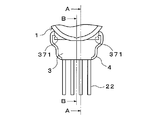
- the left and right side surfaces 13 of the electrical component body 1 are respectively formed with guide grooves 131 for guiding convex shapes 371 (described later) formed on the side portions 37 of the base member 3.
- the connector 2 includes a fixture 21 that is connected to the connection terminal 11 of the electrical component body 1 and a wiring 22 that is electrically connected to the connection terminal 11 by these fixtures.
- the fixture 21 of the present embodiment is fixed so as to be detachable from the connection terminal 11 by fitting.
- the fixing tool 21 fitted to the connection terminal 11 is reliably joined to the connection terminal 11 by soldering.
- the base member 3 includes a housing recess 31 that houses a connection portion between the connection terminal 11 and the connector 2 and has an opening 311 that opens upward (see FIGS. 1 and 7).
- the base member 3 of the present embodiment includes three ribs 32 (see FIG. 6) formed so as to protrude between the wirings 22 and protrusions 41 (described later) of the cover member 4. It has a boss hole 33 for accommodating the tip inside.
- a lower arcuate surface 36 accommodated therein is formed.
- the direction in which the wiring 22 is extended (for example, the lower left direction in FIG. 1) is referred to as “front” or “front”, and the opposite direction is “rear” or “rear”. Called.
- the guide part 35 is disposed at a position facing the lower circular arc surface 36, and a gap for accommodating and positioning the wiring 22 is formed between the guide parts 35.
- the above-described convex shapes 371 that are received in the guide grooves 131 of the electrical component main body 1 are formed.
- a stepped portion 38 for facilitating the close contact between the lower end surface 121 (see FIG. 2) of the mounting surface 12 of the electric component main body 1 on the lower side of the base member 3 and the lower end surface 121 (see FIG. 2).
- the stepped portion 38 is in close contact with the lower end surface 121, thereby providing a structure in which the sealing material 5 filled in the housing recess 31 is less likely to leak downward.
- the cover member 4 is attached to the base member 3 so as to cover the opening 311 of the housing recess 31.
- a protrusion 41 that protrudes toward the sealing material 5 filled in the housing recess 31 and is fixed to the sealing material 5 is formed on the inner surface facing the housing recess 31. (See FIGS. 2, 5, and 10 to 13).
- connection terminal 11 and the connector 2 Inside the accommodating recess 31, a connecting portion between the connection terminal 11 and the connector 2 is sealed, and the sealing member 5 for fixing the connecting portion, the base member 3 and the cover member 4 to each other (FIGS. 4 and 4). 14 (c)).
- the sealing material 5 will be described later.
- an upper concave portion 42 for accommodating the wiring 22 is formed on the front lower surface of the cover member 4.
- the upper concave portion 42 is formed at a position facing the lower concave portion 34 of the base member 3 described above, and a through hole for allowing the wiring 22 to pass outside can be formed by both of them.
- an upper arc surface 43 is formed on the front lower surface of the cover member 4 at a position facing the lower arc surface 36 of the base member 3.
- These upper and lower circular arc surfaces 36 and 43 are in close contact with each other (see FIG. 5 and FIG. 14 (d)), and can restrict the outflow of the sealing material 5 from the inside.
- the side part 44 of the cover member 4 covers the outside of the side part 37 of the base member 3 in a state where it is attached to the base member 3 (see FIGS. 3 and 14D).
- a guide groove 45 is formed on the front inner surface of the cover member 4 to accommodate the guide portion 35 of the base member 3 and improve the sealing degree between the base member 3 and the cover member 4.
- the sealing material 5 (see FIG. 4 and FIG. 14C) is filled in the housing recess 31 of the base member 3.
- the connection portion between the connection terminal 11 and the fixture 21 of the connector 2 is sealed.
- the sealing material 5 of the present embodiment fixes the connection portion between the connection terminal 11 of the electrical component body 1 and the fixture 21 of the connector 2, the inner surface of the base member 3, and the inner surface of the cover member 4. ing. More specifically, the sealing material 5 is in close contact with the surface of the mounting surface 12 of the electrical component body 1, whereby the electrical component body 1 and the wiring connector 2 are in contact with the sealing material 5.
- the fixing tool 21, the base member 3, and the cover member 4 are fixed.
- the structure of the present embodiment has a configuration in which sealing to the terminal portion by the sealing material 5 and fixing of these components can be achieved simultaneously.
- the sealing material 5 of this embodiment For example, a two-component curable type, a photocurable type, or a temperature curable type epoxy-type or acrylic-type adhesive can be used.
- the sealing material 5 of the present embodiment has a function necessary for fixing each member described above, and has a hardness sufficient to seal the connection portion of the wiring connector 2 in the cured state after filling. What is necessary is just to have.
- the photo-curing type it is preferable that the photo-curing type is cured by light transmitted through the cover member 4 or the base member 3.
- the fixture 21 of the connector 2 is attached to each connection terminal 11 in a state where the connection terminals 11 of the electrical component body 1 are exposed. Next, by soldering the two, electrical connection can be reliably performed.
- the base member 3 is disposed below the mounting surface 12 of the electrical component body 1 with the opening 311 of the housing recess 31 facing upward.
- the base member 3 is accommodated in the guide groove 131 formed in the side surface 13 of the electric component main body 1 by accommodating the protrusions 371 formed on the inner surface of the side portion 37 of the base member 3.
- an appropriate jig (not shown) may be used as an auxiliary.
- the wiring 22 of the connector 2 is accommodated and positioned in the lower recess 34 of the base member 3. Furthermore, since the rib 32 of the base member 3 is disposed between the wires, the ribs 32 can prevent the wires from being excessively approached. In the present embodiment, the wiring 22 can be positioned by accommodating the wiring 22 in a gap formed between the guide portions 35.
- the encapsulating recess 31 of the base member 3 is filled with the encapsulating material 5 in a flowable state by an encapsulating material injection means (for example, a nozzle) (not shown).
- an encapsulating material injection means for example, a nozzle
- the guide part 35 which protrudes upwards was formed in the base member 3, a possibility that a sealing material may leak from the lower side recessed part 34 can be reduced.
- connection terminal 11 and the connector 2 can be sealed by filling the sealing material 5.
- the filling amount of the sealing material 5 in the present embodiment is an amount that does not reach the opening end (the upper end in FIG. 14C) of the opening 311 of the housing recess 31, for example, 80% of the fillable volume. It is preferable to make it to the extent. If it does in this way, the leakage amount of the sealing material 5 at the time of attachment of the below-mentioned cover member 4 can be restrained low.
- the cover member 4 is attached so as to cover the opening 311 of the base member 3.
- the protruding portion 41 of the cover member 4 is fitted into the boss hole 33 of the base member 3.
- the tip of the protruding portion 41 is pushed into the sealing material 5 filled in the housing recess 31 of the base member 3 and can reliably contact the sealing material 5.
- the positioning of the cover member 4 with respect to the base member 3 can be accurately performed by fitting the protruding portion 41 into the boss hole 33.
- the upper concave portion 42 formed in front of the cover member 4 can form a through-hole between the lower concave portion 34 of the base member 3 and allow the wiring 22 to pass therethrough.
- the upper arc surface 43 of the cover member 4 is accommodated in contact with the lower arc surface 36 of the base member 3, so that the sealing material 5 is formed at the joint between the cover member 4 and the base member 3.
- the amount of leakage can be kept low.
- the sealing material 5 is cured according to the properties of the sealing material 5.
- fever required for hardening is provided to the sealing material 5.
- FIG. there exists an advantage that the connection part of the connector 2 and the connecting terminal 11 can be sealed reliably.
- the components covering the periphery of the filled sealing material 5 are fixed and fixed, so that the connector 2 and the connection terminals can be used even under severe vibration and dust conditions. 11 can be maintained.
- the opening 311 of the base member 3 (that is, the open surface of the sealing material 5) can be covered by the cover member 4 before the sealing material 5 is cured.
- the electric component main body 1 can be transported before the material 5 is cured. This also has the advantage that the time required for the manufacturing process can be shortened.
- the rib 32 is formed on the base member 3, not only can the amount of the sealing material 5 to be filled in the housing recess 31 of the base member 3 be reduced, There is also an advantage that formation of voids between the lower surface of the housing recess 31 can be suppressed.
Landscapes
- Engineering & Computer Science (AREA)
- Power Engineering (AREA)
- Connector Housings Or Holding Contact Members (AREA)
- Motor Or Generator Frames (AREA)
- Casings For Electric Apparatus (AREA)
- Details Of Connecting Devices For Male And Female Coupling (AREA)
Abstract
過酷な振動や粉塵の条件下においても、電気部品とコネクタとの間の確実な接続を維持できる接続構造またはモータを提供する。具体的には、ベース部材3は、接続端子11と配線用のコネクタ2との接続箇所を内部に収容し、かつ、上方に開口する開口部311を有する収容凹部31を備える。カバー部材4は、開口部311を覆うようにベース部材3に取り付けられている。収容凹部31の内部には、接続端子11とコネクタ2との接続箇所を封止し、かつ、この接続箇所とベース部材3とカバー部材4とを互いに固着する封止材が充填されている。
Description
本発明は、モータなどの電気部品をワイヤハーネスなどのコネクタに接続するための構造及び方法に関するものである。
モータをコネクタに接続するための構造として、本願の出願人は、例えば下記特許文献1に記載の構造を提案している。この構造では、モータ本体に接続端子を設けておき、この接続端子にワイヤハーネスのコネクタを取り付けることで、モータとワイヤハーネスとを電気的に接続できるようになっている。
ところで、車載用モータのように、過酷な振動や粉塵の条件にさらされる用途においては、電気的接続を一層確実に維持できる構造が望まれる。
本発明は、前記した状況に鑑みてなされたものである。本発明の主な目的は、過酷な振動や粉塵の条件下においても、電気部品とコネクタとの間の確実な接続を維持できる接続構造またはモータを提供することである。本発明の他の目的は、そのような接続構造またはモータを得るための接続方法を提供することである。
前記した課題を解決する手段は、以下の項目のように記載できる。
接続端子を有する電気部品本体と、前記接続端子に接続された配線用のコネクタと、ベース部材と、カバー部材とを備えており、前記ベース部材は、前記接続端子と前記コネクタとの接続箇所を内部に収容し、かつ、上方に開口する開口部を有する収容凹部を備えており、前記カバー部材は、前記開口部を覆うように前記ベース部材に取り付けられており、前記収容凹部の内部には、前記接続端子と前記コネクタとの接続箇所を封止し、かつ、前記接続箇所と前記ベース部材と前記カバー部材とを互いに固着する封止材が充填されていることを特徴とする。本発明によれば、収容凹部に充填された封止材により、接続端子とコネクタとの接続箇所を封止できる。さらに、この接続箇所とベース部材とカバー部材とが封止材を中心として互いに固定されるので、強固な封止状態を得ることができる。
本発明において、前記カバー部材における、前記収容凹部に対向する内面には、前記収容凹部に充填された前記封止材に向けて突出されて、前記封止材に固着される突出部が形成されている。したがって、突出部を封止材に固着することで、封止状態をより強固に保つことができるだけでなく、使用する封止材量を減らし、また、封止材の漏れ出しを低く抑えることができる。
本発明において、前記ベース部材は、前記突出部の先端を収容するボス穴を有していてもよい。また、前記ベース部材は、前記封止部材に向けて突出するようにリブが形成されていてもよい。さらに、前記ベース部材は、前記ベース部材の側部の内面に凸条が形成され、前記電気部品本体は、前記凸条と当接し前記ベース部材を案内する案内溝が形成されていてもよい。そのような場合には、前記カバー部材の側部は、前記ベース部材に取り付けられた状態で、前記ベース部材の側部の外側を覆うように配置されていることが望ましい。
本発明において、前記コネクタは、電気部品本体の接続端子に接続された固定具と、前記固定具により前記接続端子に電気的に接続される配線とを備えており、前記カバー部材は、前記配線を収容するための上側凹部を有し、前記ベース部材は、前記上側凹部と対向する位置に下側凹部を有し、前記上側凹部と前記下側凹部によって、配線を外部に通過させるための貫通孔が形成されていてもよい。また、本発明の前記電気部品本体は、モータであってもよい。
接続端子を有する電気部品本体と、前記接続端子に接続されたコネクタと、上方に開口された開口部を有する収容凹部を備えたベース部材と、カバー部材とを用いる電気部品の接続方法であって、前記ベース部材の前記収容凹部に前記接続端子と前記コネクタとの接続箇所が収納されるように、前記ベース部材を配置する工程と、前記収容凹部の内部に、前記接続端子と前記コネクタとの前記接続箇所を封止するように封止材を充填する工程と、前記カバー部材を、前記収容凹部における開口部を覆いかつ前記封止材に接するように、前記ベース部材に取り付ける工程と、前記封止材を硬化させることにより、前記接続端子と前記コネクタとの接続箇所と、前記ベース部材と、前記カバー部材とを互いに固着する工程とを備える電気部品の接続方法である。
本発明によれば、過酷な振動や粉塵の条件下においても、電気部品とコネクタとの間の確実な接続を維持できる接続構造またはモータを提供することができる。また、本発明によれば、そのような接続構造を得るための接続方法を提供することができる。
以下、添付図面を参照しながら、本発明の一実施形態に係る電気部品の接続構造(以下単に「接続構造」と称することがある)について説明する。
(本実施形態の構成)
本実施形態の接続構造は、電気部品本体1と、配線用のコネクタ2と、ベース部材3と、カバー部材4とを、基本的な構成要素として備えている。
本実施形態の接続構造は、電気部品本体1と、配線用のコネクタ2と、ベース部材3と、カバー部材4とを、基本的な構成要素として備えている。
(電気部品本体)
本実施形態における電気部品本体1は、特に制約されないが、例えばモータである。電気部品本体1の表面には、コネクタ2を接続するための接続端子11が、表面方向に突出するように形成されている(図1及び図2参照)。本明細書においては、接続端子11が突出している表面を、取付面12と称する。接続端子11の数は、本実施形態では、四つとされているが、特に制約されない。
本実施形態における電気部品本体1は、特に制約されないが、例えばモータである。電気部品本体1の表面には、コネクタ2を接続するための接続端子11が、表面方向に突出するように形成されている(図1及び図2参照)。本明細書においては、接続端子11が突出している表面を、取付面12と称する。接続端子11の数は、本実施形態では、四つとされているが、特に制約されない。
電気部品本体1の左右の両側面13には、ベース部材3の側部37に形成された凸状371(後述)を案内する案内溝131がそれぞれ形成されている。
(配線用コネクタ)
コネクタ2は、電気部品本体1の接続端子11にそれぞれ接続された固定具21と、これらの固定具により接続端子11に電気的に接続される配線22とを備えている。本実施形態の固定具21は、嵌合により接続端子11に着脱可能なように固定されるものである。また、本実施形態では、接続端子11に嵌合された固定具21をはんだ付けにより接続端子11に確実に接合している。ただし、固定具21を用いずに、例えばはんだ付けなどの適宜な固定手段により配線22を接続端子11に接続して接続部を構成することも可能である。
コネクタ2は、電気部品本体1の接続端子11にそれぞれ接続された固定具21と、これらの固定具により接続端子11に電気的に接続される配線22とを備えている。本実施形態の固定具21は、嵌合により接続端子11に着脱可能なように固定されるものである。また、本実施形態では、接続端子11に嵌合された固定具21をはんだ付けにより接続端子11に確実に接合している。ただし、固定具21を用いずに、例えばはんだ付けなどの適宜な固定手段により配線22を接続端子11に接続して接続部を構成することも可能である。
(ベース部材)
ベース部材3は、接続端子11とコネクタ2との接続部を内部に収容し、かつ、上方に開口する開口部311を有する収容凹部31を備えている(図1及び図7参照)。
ベース部材3は、接続端子11とコネクタ2との接続部を内部に収容し、かつ、上方に開口する開口部311を有する収容凹部31を備えている(図1及び図7参照)。
より詳しくは、本実施形態のベース部材3は、配線22の間に向けて突出するように形成された3条のリブ32(図6参照)と、カバー部材4の突出部41(後述)の先端を内部に収容するボス穴33とを備えている。
また、ベース部材3の前方側には、配線22を収容する下側凹部(34)と、カバー部材4の前側内面を案内する案内部35と、カバー部材4の上側円弧面43(後述)を内部に収容する下側円弧面36とが形成されている。なお、この実施形態の説明においては、配線22が延長されている方向(例えば図1においては左下方向)を「前方」または「前」と称し、その反対の方向を「後方」または「後」と称する。
案内部35は、下側円弧面36に対向する位置に配置されており、かつ、案内部35どうしの間には、配線22を収容して位置決めする間隙が形成されている。
さらに、ベース部材3の左右両側の側部37の内面には、前記した電気部品本体1の案内溝131に収容される前記した凸状371が形成されている。
また、ベース部材3の下側における、電気部品本体1の取付面12の下端面121(図2参照)との当接部には、両者の密着を容易とするための段差部38(図5~図7参照)が形成されている。段差部38は、下端面121に密着することにより、収容凹部31に充填された封止材5が下方に漏れにくい構造を提供している。
(カバー部材)
カバー部材4は、収容凹部31の開口部311を覆うようにベース部材3に取り付けられている。
カバー部材4は、収容凹部31の開口部311を覆うようにベース部材3に取り付けられている。
本実施形態のカバー部材4における、収容凹部31に対向する内面には、収容凹部31に充填された封止材5に向けて突出されて、封止材5に固着される突出部41が形成されている(図2、図5、図10~図13参照)。
収容凹部31の内部には、接続端子11とコネクタ2との接続箇所を封止し、かつ、この接続箇所とベース部材3とカバー部材4とを互いに固着する封止材5(図4及び図14(c)参照)が充填されている。封止材5については後述する。
また、カバー部材4の前方下面には、配線22を内部に収容するための上側凹部42が形成されている。上側凹部42は、前記したベース部材3の下側凹部34と対向する位置に形成されており、これら両者によって、配線22を外部に通過させるための貫通孔を形成できるようになっている。
さらに、カバー部材4の前方下面には、前記ベース部材3の下側円弧面36と対向する位置に、上側円弧面43が形成されている。これら上下の円弧面36及び43は、たがいに密着されており(図5及び図14(d)参照)、内部からの封止材5の流出を制限できるようになっている。
カバー部材4の側部44は、ベース部材3に取り付けられた状態では、ベース部材3の側部37の外側を覆うようになっている(図3及び図14(d)参照)。
また、カバー部材4の前方内面には、ベース部材3の案内部35を内部に収容して、ベース部材3とカバー部材4との間の密閉度を向上させる案内溝45が形成されている。
(封止材)
封止材5(図4及び図14(c)参照)は、前記したように、ベース部材3の収容凹部31の内部に充填されており、これにより、封止材5は、電気部品本体1の接続端子11とコネクタ2の固定具21との接続箇所を封止するようになっている。さらに、本実施形態の封止材5は、電気部品本体1の接続端子11とコネクタ2の固定具21との接続箇所と、ベース部材3の内面と、カバー部材4の内面とを互いに固着している。より具体的には、封止材5は、電気部品本体1の取付面12の表面に密着しており、これによって、封止材5に対して、電気部品本体1と、配線用コネクタ2の固定具21と、ベース部材3と、カバー部材4とが固定されるようになっている。その結果、本実施形態の構造では、封止材5による端子部分への封止と、これらの部品の固定とが同時に達成できる構成となっている。
封止材5(図4及び図14(c)参照)は、前記したように、ベース部材3の収容凹部31の内部に充填されており、これにより、封止材5は、電気部品本体1の接続端子11とコネクタ2の固定具21との接続箇所を封止するようになっている。さらに、本実施形態の封止材5は、電気部品本体1の接続端子11とコネクタ2の固定具21との接続箇所と、ベース部材3の内面と、カバー部材4の内面とを互いに固着している。より具体的には、封止材5は、電気部品本体1の取付面12の表面に密着しており、これによって、封止材5に対して、電気部品本体1と、配線用コネクタ2の固定具21と、ベース部材3と、カバー部材4とが固定されるようになっている。その結果、本実施形態の構造では、封止材5による端子部分への封止と、これらの部品の固定とが同時に達成できる構成となっている。
本実施形態の封止材5としては、特に制約されないが、例えば二液硬化型や光硬化型や温度硬化型の、エポキシ系やアクリル系の接着剤を用いることができる。ただし、本実施形態の封止材5としては、前記した各部材の固着に必要な機能を有し、かつ、充填後の硬化状態において配線用コネクタ2の接続部分を封止するに十分な硬度を有するものであればよい。また、光硬化型の場合、カバー部材4又はベース部材3を透過する光により硬化
するものであることが好ましい。
するものであることが好ましい。
(本実施形態における電気部品の接続方法)
次に、前記した接続構造を形成するための、電気部品の接続方法を、主に図14を参照しながら説明する。
次に、前記した接続構造を形成するための、電気部品の接続方法を、主に図14を参照しながら説明する。
(図14(a)及び(b))
まず、電気部品本体1の接続端子11が露出した状態において、コネクタ2の固定具21を各接続端子11に取り付ける。ついで両者をはんだ付けすることにより、電気的な接続を確実に行うことができる。
まず、電気部品本体1の接続端子11が露出した状態において、コネクタ2の固定具21を各接続端子11に取り付ける。ついで両者をはんだ付けすることにより、電気的な接続を確実に行うことができる。
(図14(c))
次に、電気部品本体1の取付面12の下方に、ベース部材3を、収容凹部31の開口部311が上方に向いた状態で配置する。この状態では、ベース部材3の側部37の内面に形成された凸条371を、電気部品本体1の側面13に形成された案内溝131に収容することによって、ベース部材3を電気部品本体1に対して位置決めすることができる。なお、ベース部材3の位置決めとしては、適宜な治具(図示せず)を補助的に用いてもよい。
次に、電気部品本体1の取付面12の下方に、ベース部材3を、収容凹部31の開口部311が上方に向いた状態で配置する。この状態では、ベース部材3の側部37の内面に形成された凸条371を、電気部品本体1の側面13に形成された案内溝131に収容することによって、ベース部材3を電気部品本体1に対して位置決めすることができる。なお、ベース部材3の位置決めとしては、適宜な治具(図示せず)を補助的に用いてもよい。
この状態では、コネクタ2の配線22は、ベース部材3の下側凹部34の内部に収容されて位置決めされる。さらに各配線間には、ベース部材3のリブ32が配置されるので、配線どうしの過剰な接近をリブ32により阻止できる。また、本実施形態では、案内部35どうしの間に形成された間隙に配線22を収容することによって、配線22の位置決めを行うこともできる。
ついで、図示しない封止材注入手段(例えばノズル)により、流動可能な状態の封止材5を、ベース部材3の収容凹部31に充填する。本実施形態では、ベース部材3に、上方に突出する案内部35を形成したので、下側凹部34から封止材が漏れ出すおそれを低減することができる。
この封止材5の充填作業により、接続端子11とコネクタ2との接続箇所を封止することができる。
ここで、本実施形態における封止材5の充填量としては、収容凹部31の開口部311の開口端(図14(c)において上端)までには達しない量、例えば充填可能容積の80%程度までとすることが好ましい。このようにすると、後述のカバー部材4の取付時における封止材5の漏れ出し量を低く抑えることができる。
(図14(d))
ついで、カバー部材4を、ベース部材3の開口部311を覆うようにして取り付ける。このとき、カバー部材4の突出部41をベース部材3のボス穴33に嵌入させる。すると、突出部41の先端は、ベース部材3の収容凹部31に充填された封止材5の中に押し込まれて、この封止材5に確実に接触することができる。また、本実施形態では、突出部41をボス穴33に嵌入させることにより、ベース部材3に対するカバー部材4の位置決めを正確に行うこともできる。
ついで、カバー部材4を、ベース部材3の開口部311を覆うようにして取り付ける。このとき、カバー部材4の突出部41をベース部材3のボス穴33に嵌入させる。すると、突出部41の先端は、ベース部材3の収容凹部31に充填された封止材5の中に押し込まれて、この封止材5に確実に接触することができる。また、本実施形態では、突出部41をボス穴33に嵌入させることにより、ベース部材3に対するカバー部材4の位置決めを正確に行うこともできる。
また、カバー部材4の前方に形成された上側凹部42は、前記したように、ベース部材3の下側凹部34との間において貫通孔を形成して、配線22を通過させることができる。
さらに、本実施形態では、カバー部材4の上側円弧面43がベース部材3の下側円弧面36に当接して収容されるので、カバー部材4とベース部材3との接合部において封止材5が漏れ出す量を低く抑えることができる。
また、本実施形態では、ベース部材3の突出部35をカバー部材4の案内溝45に収容することにより、カバー部材4を一層効率的に位置決めできるだけでなく、両者の嵌め合いにより、封止材5の漏れ出しを制約することができるという利点もある。
ついで、封止材5の性質に応じて、封止材5を硬化させる。例えば、熱硬化性樹脂であれば、硬化に必要な熱を封止材5に付与する。これにより、本実施形態の構造においては、コネクタ2と接続端子11との接続部分を、確実に封止することができるという利点がある。さらに、本実施形態では、充填された封止材5を中心として、その周囲を覆う各部品を固着して固定しているので、過酷な振動や粉塵の条件下においても、コネクタ2と接続端子11との間の確実な接続を維持することができる。
また、本実施形態の製造方法では、封止材5の硬化前に、カバー部材4により、ベース部材3の開口部311(つまり封止材5の開放面)を覆うことができるので、封止材5の硬化前に電気部品本体1を搬送することができる。これにより、製造工程における所要時間を短縮することができるという利点もある。
また、本実施形態の構成では、ベース部材3にリブ32を形成したので、ベース部材3の収容凹部31に充填すべき封止材5の量を減らすことができるだけでなく、封止材5と収容凹部31下面との間におけるボイドの形成を抑制できるという利点もある。
なお、本発明は、前記した実施の形態に限定されるものではなく、本発明の要旨を逸脱しない範囲内において種々の変更を加え得るものである。
1 電気部品本体、11 接続端子、12 取付面、13 電気部品本体の側面、131 案内溝、2 コネクタ、21 固定具、22 配線、3 ベース部材、31 収容凹部、311 開口部、32 リブ、33 ボス穴、34 下側凹部、35 案内部、36 下側円弧面、37 ベース部材の側部、371 凸状、38 段差部、4 カバー部材、41 突出部、42 上側凹部、43 上側円弧面、44 カバー部材の側部、5 封止材、
Claims (9)
- 接続端子を有する電気部品本体と、前記接続端子に接続された配線用のコネクタと、ベース部材と、カバー部材とを備えており、
前記ベース部材は、前記接続端子と前記コネクタとの接続箇所を内部に収容し、かつ、上方に開口する開口部を有する収容凹部を備えており、
前記カバー部材は、前記開口部を覆うように前記ベース部材に取り付けられており、
前記収容凹部の内部には、前記接続端子と前記コネクタとの前記接続箇所を封止し、かつ、前記接続箇所と前記ベース部材と前記カバー部材とを互いに固着する封止材が充填されていることを特徴とする電気部品の接続構造。 - 前記カバー部材における、前記収容凹部に対向する内面には、前記収容凹部に充填された前記封止材に向けて突出されて、前記封止材に固着される突出部が形成されていることを特徴とする請求項1に記載の電気部品の接続構造。
- 前記ベース部材は、前記突出部の先端を収容するボス穴を有することを特徴とする請求項2に記載の電気部品の接続構造。
- 前記ベース部材は、前記封止部材に向けて突出するようにリブが形成されていることを特徴とする請求項1に記載の電気部品の接続構造。
- 前記ベース部材は、前記ベース部材の側部の内面に凸条が形成され、
前記電気部品本体は、前記凸条と当接し前記ベース部材を案内する案内溝が形成されていることを特徴とする請求項1に記載の電気部品の接続構造。 - 前記カバー部材の側部は、前記ベース部材に取り付けられた状態で、前記ベース部材の側部の外側を覆うように配置されることを特徴とする請求項5に記載の電気部品の接続構造。
- 前記コネクタは、電気部品本体の接続端子に接続された固定具と、前記固定具により前記接続端子に電気的に接続される配線とを備えており、
前記カバー部材は、前記配線を収容するための上側凹部を有し、
前記ベース部材は、前記上側凹部と対向する位置に下側凹部を有し、
前記上側凹部と前記下側凹部によって、配線を外部に通過させるための貫通孔が形成されている事を特徴とする請求項1に記載の電気部品の接続構造。 - 前記電気部品本体は、モータであり、
請求項1から7のうちいずれかの項に記載の電気部品の接続構造を有することを特徴とするモータ。 - 接続端子を有する電気部品本体と、前記接続端子に接続されたコネクタと、上方に開口された開口部を有する収容凹部を備えたベース部材と、カバー部材とを用いる電気部品の接続方法であって、
前記ベース部材の前記収容凹部に前記接続端子と前記コネクタとの接続箇所が収納されるように、前記ベース部材を配置する工程と、
前記収容凹部の内部に、前記接続端子と前記コネクタとの前記接続箇所を封止するように封止材を充填する工程と、
前記カバー部材を、前記収容凹部における開口部を覆いかつ前記封止材に接するように、前記ベース部材に取り付ける工程と、
前記封止材を硬化させることにより、前記接続端子と前記コネクタとの接続箇所と、前記ベース部材と、前記カバー部材とを互いに固着する工程とを備える電気部品の接続方法。
Priority Applications (3)
| Application Number | Priority Date | Filing Date | Title |
|---|---|---|---|
| US16/490,597 US11539262B2 (en) | 2017-03-03 | 2018-02-07 | Connection structure of electric component, motor and connection method of electric component |
| CN201880015363.9A CN110392962B (zh) | 2017-03-03 | 2018-02-07 | 电子零件的连接结构及马达、电子零件的连接方法 |
| DE112018001125.9T DE112018001125T5 (de) | 2017-03-03 | 2018-02-07 | Verbindungsstruktur einer elektrokomponente, motor und verfahren zum verbinden einer elektrokomponente |
Applications Claiming Priority (2)
| Application Number | Priority Date | Filing Date | Title |
|---|---|---|---|
| JP2017-040317 | 2017-03-03 | ||
| JP2017040317A JP2018147650A (ja) | 2017-03-03 | 2017-03-03 | 電気部品の接続構造及び電気部品の接続方法 |
Publications (1)
| Publication Number | Publication Date |
|---|---|
| WO2018159239A1 true WO2018159239A1 (ja) | 2018-09-07 |
Family
ID=63370762
Family Applications (1)
| Application Number | Title | Priority Date | Filing Date |
|---|---|---|---|
| PCT/JP2018/004144 WO2018159239A1 (ja) | 2017-03-03 | 2018-02-07 | 電気部品の接続構造及びモータ、電気部品の接続方法 |
Country Status (5)
| Country | Link |
|---|---|
| US (1) | US11539262B2 (ja) |
| JP (1) | JP2018147650A (ja) |
| CN (1) | CN110392962B (ja) |
| DE (1) | DE112018001125T5 (ja) |
| WO (1) | WO2018159239A1 (ja) |
Families Citing this family (1)
| Publication number | Priority date | Publication date | Assignee | Title |
|---|---|---|---|---|
| JP7354904B2 (ja) * | 2020-03-31 | 2023-10-03 | ニデック株式会社 | モータユニット |
Citations (5)
| Publication number | Priority date | Publication date | Assignee | Title |
|---|---|---|---|---|
| JPS5126482U (ja) * | 1974-08-19 | 1976-02-26 | ||
| JP3019353U (ja) * | 1995-06-13 | 1995-12-12 | トーソク株式会社 | 絶縁キャップ |
| JPH11242968A (ja) * | 1998-02-25 | 1999-09-07 | Yazaki Corp | 防水保護カバー |
| JP2002325005A (ja) * | 2001-04-25 | 2002-11-08 | Alps Electric Co Ltd | アンテナの防水構造 |
| JP2009087855A (ja) * | 2007-10-02 | 2009-04-23 | Furukawa Electric Co Ltd:The | フレキシブルフラットハーネス及びその製造方法並びにスライドドアの給電装置 |
Family Cites Families (12)
| Publication number | Priority date | Publication date | Assignee | Title |
|---|---|---|---|---|
| JPS5126482A (ja) | 1974-08-30 | 1976-03-04 | Hitachi Ltd | Handotaisochinohaisenhoho |
| US4523117A (en) * | 1978-06-16 | 1985-06-11 | Emerson Electric Co. | Dynamoelectric machine with self-sealing lead wire grommet |
| JP3019353B2 (ja) | 1990-02-27 | 2000-03-13 | ソニー株式会社 | 充電装置 |
| JPH07242968A (ja) | 1994-03-01 | 1995-09-19 | Mitsubishi Materials Corp | 耐食性に優れたZr合金 |
| US5767596A (en) * | 1996-10-03 | 1998-06-16 | General Electric Company | Dynamoelectric machine and processes for making the same |
| JPH11224720A (ja) * | 1998-02-06 | 1999-08-17 | Sumitomo Wiring Syst Ltd | コネクタ |
| JP3790958B2 (ja) * | 2001-10-12 | 2006-06-28 | ミネベア株式会社 | レゾルバのリード端子構造 |
| US6809445B2 (en) * | 2002-04-04 | 2004-10-26 | General Electric Company | Method and apparatus for electric motor lead wire retention |
| JP2005253138A (ja) | 2004-03-01 | 2005-09-15 | Mitsubishi Material Cmi Kk | モータ |
| CN2749072Y (zh) * | 2004-09-29 | 2005-12-28 | 史秋伟 | 一种设于电缆线之连接器 |
| CN201243104Y (zh) * | 2008-06-25 | 2009-05-20 | 昆盈企业股份有限公司 | 计算机外设装置的电气连接结构 |
| CN203415751U (zh) * | 2013-08-15 | 2014-01-29 | 深圳市康瑞通精密仪器有限公司 | 一种可拆分式医用接头 |
-
2017
- 2017-03-03 JP JP2017040317A patent/JP2018147650A/ja active Pending
-
2018
- 2018-02-07 DE DE112018001125.9T patent/DE112018001125T5/de active Pending
- 2018-02-07 CN CN201880015363.9A patent/CN110392962B/zh not_active Expired - Fee Related
- 2018-02-07 WO PCT/JP2018/004144 patent/WO2018159239A1/ja active Application Filing
- 2018-02-07 US US16/490,597 patent/US11539262B2/en active Active
Patent Citations (5)
| Publication number | Priority date | Publication date | Assignee | Title |
|---|---|---|---|---|
| JPS5126482U (ja) * | 1974-08-19 | 1976-02-26 | ||
| JP3019353U (ja) * | 1995-06-13 | 1995-12-12 | トーソク株式会社 | 絶縁キャップ |
| JPH11242968A (ja) * | 1998-02-25 | 1999-09-07 | Yazaki Corp | 防水保護カバー |
| JP2002325005A (ja) * | 2001-04-25 | 2002-11-08 | Alps Electric Co Ltd | アンテナの防水構造 |
| JP2009087855A (ja) * | 2007-10-02 | 2009-04-23 | Furukawa Electric Co Ltd:The | フレキシブルフラットハーネス及びその製造方法並びにスライドドアの給電装置 |
Also Published As
| Publication number | Publication date |
|---|---|
| CN110392962A (zh) | 2019-10-29 |
| CN110392962B (zh) | 2021-03-09 |
| DE112018001125T5 (de) | 2019-12-05 |
| US20200014275A1 (en) | 2020-01-09 |
| JP2018147650A (ja) | 2018-09-20 |
| US11539262B2 (en) | 2022-12-27 |
Similar Documents
| Publication | Publication Date | Title |
|---|---|---|
| US7789696B2 (en) | Waterproof case for electrical apparatus | |
| WO2013084493A1 (en) | Connector and manufacturing method thereof | |
| US20180020558A1 (en) | Electronic Control Device | |
| JP2014086349A (ja) | コネクタ | |
| JP2018190639A (ja) | コネクタ及びコネクタ製造方法 | |
| KR20150052755A (ko) | 배터리 셀 연결보드 | |
| JP2015072797A (ja) | コネクタ | |
| JP6486419B2 (ja) | コネクタ | |
| WO2013183305A1 (en) | Connector | |
| WO2018159239A1 (ja) | 電気部品の接続構造及びモータ、電気部品の接続方法 | |
| JP7089486B2 (ja) | モーターコネクター及びこれを有するモーター | |
| JP2017192228A (ja) | 電動機の防水構造 | |
| JP2015018617A (ja) | コネクタハウジング、コネクタ及びコネクタ接続構造 | |
| JP2019053943A (ja) | モジュール用コネクタ | |
| KR101448511B1 (ko) | 밀폐형 복합터미널 커넥터 | |
| US9735496B1 (en) | Electronics unit | |
| KR101626371B1 (ko) | 카메라용 케이블 조립체 및 카메라용 케이블 조립체의 제작방법 | |
| KR102238646B1 (ko) | 커넥터 | |
| JP5766529B2 (ja) | フラットケーブルの防水コネクタ構造 | |
| JP5708855B1 (ja) | 電気コネクタの製造方法 | |
| JP2019114523A (ja) | コネクタ及びコネクタアセンブリ | |
| JP2014194899A (ja) | 防水コネクタ | |
| JP2019097339A (ja) | 保護部品及び保護方法 | |
| CN211702660U (zh) | 一种控制器罩壳连接结构 | |
| WO2024062981A1 (ja) | コネクタ |
Legal Events
| Date | Code | Title | Description |
|---|---|---|---|
| 121 | Ep: the epo has been informed by wipo that ep was designated in this application |
Ref document number: 18761422 Country of ref document: EP Kind code of ref document: A1 |
|
| 122 | Ep: pct application non-entry in european phase |
Ref document number: 18761422 Country of ref document: EP Kind code of ref document: A1 |