WO2018155580A1 - シール構造および該シール構造を備える装置 - Google Patents
シール構造および該シール構造を備える装置 Download PDFInfo
- Publication number
- WO2018155580A1 WO2018155580A1 PCT/JP2018/006538 JP2018006538W WO2018155580A1 WO 2018155580 A1 WO2018155580 A1 WO 2018155580A1 JP 2018006538 W JP2018006538 W JP 2018006538W WO 2018155580 A1 WO2018155580 A1 WO 2018155580A1
- Authority
- WO
- WIPO (PCT)
- Prior art keywords
- needle
- seal
- hole
- fluid chamber
- fluid
- Prior art date
Links
Images


Classifications
-
- F—MECHANICAL ENGINEERING; LIGHTING; HEATING; WEAPONS; BLASTING
- F16—ENGINEERING ELEMENTS AND UNITS; GENERAL MEASURES FOR PRODUCING AND MAINTAINING EFFECTIVE FUNCTIONING OF MACHINES OR INSTALLATIONS; THERMAL INSULATION IN GENERAL
- F16K—VALVES; TAPS; COCKS; ACTUATING-FLOATS; DEVICES FOR VENTING OR AERATING
- F16K41/00—Spindle sealings
- F16K41/02—Spindle sealings with stuffing-box ; Sealing rings
- F16K41/04—Spindle sealings with stuffing-box ; Sealing rings with at least one ring of rubber or like material between spindle and housing
-
- F—MECHANICAL ENGINEERING; LIGHTING; HEATING; WEAPONS; BLASTING
- F16—ENGINEERING ELEMENTS AND UNITS; GENERAL MEASURES FOR PRODUCING AND MAINTAINING EFFECTIVE FUNCTIONING OF MACHINES OR INSTALLATIONS; THERMAL INSULATION IN GENERAL
- F16J—PISTONS; CYLINDERS; SEALINGS
- F16J15/00—Sealings
- F16J15/50—Sealings between relatively-movable members, by means of a sealing without relatively-moving surfaces, e.g. fluid-tight sealings for transmitting motion through a wall
- F16J15/52—Sealings between relatively-movable members, by means of a sealing without relatively-moving surfaces, e.g. fluid-tight sealings for transmitting motion through a wall by means of sealing bellows or diaphragms
-
- B—PERFORMING OPERATIONS; TRANSPORTING
- B05—SPRAYING OR ATOMISING IN GENERAL; APPLYING FLUENT MATERIALS TO SURFACES, IN GENERAL
- B05B—SPRAYING APPARATUS; ATOMISING APPARATUS; NOZZLES
- B05B1/00—Nozzles, spray heads or other outlets, with or without auxiliary devices such as valves, heating means
- B05B1/30—Nozzles, spray heads or other outlets, with or without auxiliary devices such as valves, heating means designed to control volume of flow, e.g. with adjustable passages
- B05B1/3033—Nozzles, spray heads or other outlets, with or without auxiliary devices such as valves, heating means designed to control volume of flow, e.g. with adjustable passages the control being effected by relative coaxial longitudinal movement of the controlling element and the spray head
- B05B1/304—Nozzles, spray heads or other outlets, with or without auxiliary devices such as valves, heating means designed to control volume of flow, e.g. with adjustable passages the control being effected by relative coaxial longitudinal movement of the controlling element and the spray head the controlling element being a lift valve
- B05B1/3046—Nozzles, spray heads or other outlets, with or without auxiliary devices such as valves, heating means designed to control volume of flow, e.g. with adjustable passages the control being effected by relative coaxial longitudinal movement of the controlling element and the spray head the controlling element being a lift valve the valve element, e.g. a needle, co-operating with a valve seat located downstream of the valve element and its actuating means, generally in the proximity of the outlet orifice
-
- B—PERFORMING OPERATIONS; TRANSPORTING
- B05—SPRAYING OR ATOMISING IN GENERAL; APPLYING FLUENT MATERIALS TO SURFACES, IN GENERAL
- B05C—APPARATUS FOR APPLYING FLUENT MATERIALS TO SURFACES, IN GENERAL
- B05C11/00—Component parts, details or accessories not specifically provided for in groups B05C1/00 - B05C9/00
- B05C11/10—Storage, supply or control of liquid or other fluent material; Recovery of excess liquid or other fluent material
- B05C11/1002—Means for controlling supply, i.e. flow or pressure, of liquid or other fluent material to the applying apparatus, e.g. valves
- B05C11/1026—Valves
-
- B—PERFORMING OPERATIONS; TRANSPORTING
- B05—SPRAYING OR ATOMISING IN GENERAL; APPLYING FLUENT MATERIALS TO SURFACES, IN GENERAL
- B05C—APPARATUS FOR APPLYING FLUENT MATERIALS TO SURFACES, IN GENERAL
- B05C5/00—Apparatus in which liquid or other fluent material is projected, poured or allowed to flow on to the surface of the work
- B05C5/02—Apparatus in which liquid or other fluent material is projected, poured or allowed to flow on to the surface of the work the liquid or other fluent material being discharged through an outlet orifice by pressure, e.g. from an outlet device in contact or almost in contact, with the work
- B05C5/0225—Apparatus in which liquid or other fluent material is projected, poured or allowed to flow on to the surface of the work the liquid or other fluent material being discharged through an outlet orifice by pressure, e.g. from an outlet device in contact or almost in contact, with the work characterised by flow controlling means, e.g. valves, located proximate the outlet
-
- F—MECHANICAL ENGINEERING; LIGHTING; HEATING; WEAPONS; BLASTING
- F16—ENGINEERING ELEMENTS AND UNITS; GENERAL MEASURES FOR PRODUCING AND MAINTAINING EFFECTIVE FUNCTIONING OF MACHINES OR INSTALLATIONS; THERMAL INSULATION IN GENERAL
- F16J—PISTONS; CYLINDERS; SEALINGS
- F16J15/00—Sealings
- F16J15/16—Sealings between relatively-moving surfaces
- F16J15/18—Sealings between relatively-moving surfaces with stuffing-boxes for elastic or plastic packings
- F16J15/24—Sealings between relatively-moving surfaces with stuffing-boxes for elastic or plastic packings with radially or tangentially compressed packing
-
- F—MECHANICAL ENGINEERING; LIGHTING; HEATING; WEAPONS; BLASTING
- F16—ENGINEERING ELEMENTS AND UNITS; GENERAL MEASURES FOR PRODUCING AND MAINTAINING EFFECTIVE FUNCTIONING OF MACHINES OR INSTALLATIONS; THERMAL INSULATION IN GENERAL
- F16J—PISTONS; CYLINDERS; SEALINGS
- F16J15/00—Sealings
- F16J15/46—Sealings with packing ring expanded or pressed into place by fluid pressure, e.g. inflatable packings
- F16J15/48—Sealings with packing ring expanded or pressed into place by fluid pressure, e.g. inflatable packings influenced by the pressure within the member to be sealed
-
- F—MECHANICAL ENGINEERING; LIGHTING; HEATING; WEAPONS; BLASTING
- F16—ENGINEERING ELEMENTS AND UNITS; GENERAL MEASURES FOR PRODUCING AND MAINTAINING EFFECTIVE FUNCTIONING OF MACHINES OR INSTALLATIONS; THERMAL INSULATION IN GENERAL
- F16K—VALVES; TAPS; COCKS; ACTUATING-FLOATS; DEVICES FOR VENTING OR AERATING
- F16K1/00—Lift valves or globe valves, i.e. cut-off apparatus with closure members having at least a component of their opening and closing motion perpendicular to the closing faces
- F16K1/32—Details
- F16K1/34—Cutting-off parts, e.g. valve members, seats
- F16K1/46—Attachment of sealing rings
Definitions
- the present invention relates to a seal structure and an apparatus including the seal structure.
- the needle In the needle type valve, in order to prevent the fluid from entering the drive chamber from the fluid chamber, the needle is provided with a seal structure that separates the fluid chamber from the drive chamber. This is because when the fluid enters the drive chamber, it causes malfunction, and in the worst case, it may become inoperable.
- an O-ring In general, an O-ring is often used as the seal structure.
- a rod seal for example, Patent Document 1
- a diaphragm for example, Patent Document 2 in which a needle slides in a through hole. Etc. may be used.
- Patent Document 1 discloses that in an applicator that dispenses liquid by reciprocating movement of a valve rod, a pair of dynamic seals (90, 92) are provided in the main body (14), and the first movement is performed.
- the static seal (90) prevents liquid in the liquid flow path from leaking or moving into the piston chamber at the top of the body, and the second dynamic seal (92) prevents air in the piston chamber from flowing.
- An applicator is disclosed ([0014]) that prevents leakage or movement into the liquid flow path.
- Patent Document 2 discloses that in a needle valve that discharges paint by periodically opening and closing a needle, a diaphragm (25) is formed between an outer cylinder (22a) of a casing (22) and a liquid chamber case (29).
- a needle valve is disclosed ([0015] to [0016]) in which a needle (34) fitted to the nozzle opening (30) is coupled to the liquid chamber side of the diaphragm (25).
- an object of the present invention is to provide a seal structure in which a needle and a seal do not slide and can be easily attached and detached, and an apparatus including the seal structure.
- the seal of the present invention is a seal into which a needle of a valve device including a fluid chamber having an outflow hole and an inflow hole and a needle whose tip reciprocates in the fluid chamber is inserted, and the needle into which the needle is inserted
- a main body portion made of an elastic body in which an insertion hole is formed; and a flange portion (104, 105) made of an elastic body extending in an annular shape radially outward from the main body portion, and one of the needle insertion holes
- the end opening diameter (D 3 ) is smaller than the other end opening diameter (D 2 ) of the needle insertion hole.
- the main body portion and the collar portion may be integrally formed.
- the needle insertion hole includes (a) a first diameter, a second diameter, and a stepped portion, (b) an inner peripheral surface has a tapered cross section, (c) an inner periphery The surface may have a curved cross section that bulges inward, or (d) the inner peripheral surface may have a curved cross section that bulges outward.
- the seal may be characterized in that a protruding portion that protrudes to at least one of the outflow hole side and the opposite side of the outflow hole is formed on the outer peripheral portion (105) of the collar portion.
- the seal may be characterized in that the flange portions (104, 105) extend radially outward from a position closer to the end portion on the opposite side to the outflow hole than the end portion on the outflow hole side.
- the collar portion (104, 105) may be extended radially outward from an end portion of the main body portion opposite to the outflow hole.
- a seal structure according to a first aspect of the present invention is a seal structure of a valve device including a fluid chamber having an outflow hole and an inflow hole, and a needle whose tip reciprocates in the fluid chamber, the seal and the seal And an end opening diameter (D 3 ) on the outflow hole side of the needle insertion hole and an end opening diameter (D 3 ) on the opposite side to the outflow hole of the needle insertion hole.
- Any of 2 ) is characterized in that it has a smaller diameter than the diameter (D 1 ) of the needle.
- a seal structure is a seal structure of a valve device including a fluid chamber having an outflow hole and an inflow hole, and a needle whose tip reciprocates in the fluid chamber, the seal and the fluid
- One includes a step portion (215) that abuts on a surface adjacent to the outer peripheral end of the collar portion, and the first housing member (207) and the second housing member ( 06) are connected in a state where the outer peripheral portion (105) of the collar portion is narrowed, and when the needle reciprocates, the inner peripheral portion (104) of the collar portion follows and deforms, thereby the needle.
- an end opening diameter (D 3 ) on the outflow hole side of the needle insertion hole and an end opening diameter (D 2) on the opposite side of the needle insertion hole from the outflow hole. ) May have a smaller diameter than the diameter (D 1 ) of the needle.
- the valve device of the present invention includes the above-mentioned seal, a fluid chamber having an outflow hole and an inflow hole, a needle whose tip reciprocates within the fluid chamber, a housing in which the fluid chamber is formed, and a needle that reciprocates the needle.
- the second housing is narrower than the needle, and the housing includes a first housing member (207) including the fluid chamber and a driving chamber (204) wider than the needle through which the needle is inserted.
- the needle driving device may include an actuator, and may further include a stroke adjusting mechanism that adjusts a stroke of the needle.
- the fluid discharge device of the present invention comprises the valve device, a storage container fluidly connected to the inflow hole, a nozzle having a discharge port fluidly connected to the outflow hole, and the operation of the valve device. And a valve control device for controlling.
- the storage container may be a storage container of a liquid material
- the needle is advanced and collided with a valve seat that is an entrance portion of the outflow hole
- the present invention may be characterized by being a jet-type discharge device that moves the needle forward and stops immediately before it collides with the valve seat, and causes droplets to fly and discharge from the discharge port.
- the coating apparatus of the present invention includes the fluid ejection device, a stage on which an object to be coated is placed, a relative drive device that relatively moves the fluid ejection device and the stage, and a stage that controls the operation of the relative drive device. And a control device.
- the needle since the needle does not slide with the seal, the problems of heat generation and wear that occur in the seal can be solved. Further, the seal can be easily attached and detached without requiring tools or skills.
- FIG. (A) is principal part sectional drawing of the seal
- (b) is principal part sectional drawing of the seal
- (c) is principal part sectional drawing of the seal
- (D) is principal part sectional drawing of the seal
- (e) is principal part sectional drawing of the seal
- (f) is principal part sectional drawing of the seal
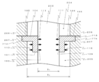
- FIG. (A) is sectional drawing of the seal
- (b) is sectional drawing of the seal
- the seal structure exemplified in the first to twelfth embodiments is mainly used for a dispenser that discharges a liquid material by opening and closing a valve seat at the tip of a needle.
- the seal structure of the present invention is an arbitrary fluid.
- the present invention can be applied to a valve for controlling the flow of air.
- the seal structure according to the first embodiment includes a seal 101, upper and lower housing members (206, 207) in which a fluid chamber 205 is formed, and a needle 203.
- the seal 101 is formed so as to penetrate a cylindrical main body 102, a main body 102, a through hole 103 having different inner diameters on the upper side and the lower side, and an outer periphery of the main body 102.
- a flange portion (104, 105) formed in a shape.
- the main body 102 is a cylindrical member and extends in a direction parallel to the needle 203 (that is, the vertical direction).
- the length (H 1 + H 2 ) of the main body 102 is, for example, 2 to 4 mm.
- the thickness H 1 of the collar (104, 105) (or the thickness W 1 of the through-hole side wall 111) For example, 2 to 5 times.
- a high holding force can be realized by setting the length (H 1 + H 2 ) of the main body 102 to a certain value or more.
- the outer diameter (D 4 ) of the main body 102 is configured to be smaller than the inner diameter (D 0 ) of the fluid chamber 205 so that the main body portion 102 can operate without contacting the inner wall of the fluid chamber 205.
- the through hole 103 is a through hole that penetrates the center of the main body 102 in a direction parallel to the needle 203 (that is, the vertical direction).
- the inner diameter of the upper end face 106 and the inner diameter of the lower end face 107 constituting the end face of the through-hole 103 are both smaller than the outer diameter of the needle 203, and the lower end face 107 is smaller than the inner diameter of the upper end face 106.
- the inner diameter is smaller. That, D 1 the outer diameter of the needle 203, when the inner diameter of the through-hole 103 upper end surface 106 D 2, the inner diameter of the lower end surface 107 of the through hole 103 and D 3, the relationship D 1> D 2> D 3 It holds.
- the needle 203 and the seal 101 can be easily attached and detached. Because the upper side of the needle 203 is connected to the needle driving device 202, the needle 203 is inserted into the seal 101 from the upper side of the seal 101 having a large inner diameter, and the needle 203 is also removed from the seal 101. This is because it is performed by moving the seal 101 having a large inner diameter to the upper side.
- the step portion 108 is provided in the through hole 103, but other shapes may be used (for example, see FIG. 4 described later).
- the collar portions (104, 105) are annular plate-like members formed in a convex shape from the outer periphery of the main body portion 102 toward the outer side in the radial direction, and include an inner peripheral portion 104 and an outer peripheral portion 105.
- the main body portion 102 and the collar portions (104, 105) are preferably configured integrally.
- the collar portions (104, 105) can be extended outward in the radial direction with a slight angle (for example, an angle of 15 degrees or less) with the horizontal plane, but are preferably extended in the horizontal direction as in this embodiment. .
- the shape of the collar portion (104, 105) viewed from the upper surface does not need to be a perfect circle, and the above-described annular shape includes a shape having a corner portion or a concave portion in a part of the outer peripheral edge, or a polygon.
- the inner peripheral part 104 is an inner part of the collar part, and connects the main body part 102 and the outer peripheral part 105. From another viewpoint, a portion corresponding to the inner diameter of the fluid chamber 205 of the collar portion to the outer diameter of the main body portion 102 corresponds to the inner peripheral portion 104.
- the thickness H 1 of the inner peripheral portion 104 is, for example, 0.2 to 2 mm.
- the horizontal thickness of the main body 102 (the value obtained by subtracting the inner diameter (D 2 ) of the through hole 103 from the outer diameter (D 4 ) of the main body 102 and dividing it by 2, for example, 0.5 to The thickness is 3 times. If it is too thick, elastic deformation is unlikely to occur, and the needle 203 may slide with the through-hole side wall 111. Since the inner peripheral portion 104 is elastically deformed between the main body portion 102 and the outer peripheral portion 105, the needle 203 does not slide in the through hole 103 of the seal 101, and the needle 203 can be appropriately operated.
- the collar portions (104, 105) are provided at the upper end portion 121 of the main body portion 102, but may be provided at a position below the upper end portion 121 as will be described later (for example, described later). FIG. 6).
- the outer peripheral part 105 is a part outside the collar part, and is formed at the outer end of the inner peripheral part 104. From another viewpoint, the portion sandwiched between the upper and lower housing members (206, 207) of the collar portion corresponds to the outer peripheral portion 105. The outer peripheral portion 105 is sandwiched and fixed between the upper and lower housing members (206, 207), thereby defining the position of the seal 101 in the fluid chamber 205. If the outer peripheral portion 105 is too thin, the amount of deformation at the time of narrow pressure fixing by the upper and lower housings (206, 207) cannot be secured, and a certain thickness is required.
- the thickness of the outer peripheral portion 105 in the present embodiment is H 1 that is the same as the thickness of the inner peripheral portion 104.
- the outer peripheral portion 105 has the same shape as the inner peripheral portion 104 and has a shape that extends outward in the radial direction. However, as described later, other shapes may be used (for example, described later). FIG. 5).
- the seal 101 is made of an elastic material, and particularly rubber is used in this embodiment. More specifically, for example, the use of silicone rubber, fluorine rubber, nitrile rubber, acrylic rubber, or urethane rubber is disclosed. As shown in FIG. 2, the needle 101 is inserted into the through hole 103 and the outer peripheral portion 105 is sandwiched between the upper and lower housing members (206, 207) and positioned in the fluid chamber 205.
- an annular recess (expanded diameter portion) is formed at the upper end of the lower housing member 207.
- the inner peripheral wall of the recess is referred to as an enlarged wall 213, and the inner bottom surface is referred to as a step 215.
- the inner periphery of the expanded wall 213 and the outer periphery of the collar portion (104, 105) have substantially the same diameter.
- the height of the enlarged diameter wall 213, flange portions (104, 105) is constituted of a height H 1 from the slightly lower, collapsing to press the upper surface of the seal 101 at the end face of the upper housing member 206 (bottom) This improves the sealing performance.
- the seal 101 is fixed to the upper and lower housing members (206, 207) by pressing with the end surfaces of the upper and lower housing members (206, 207), the attaching / detaching operation of the seal 101 can be easily performed. Can do.
- the upper and lower housing members (206, 207) are detachably connected by a connection mechanism (not shown).
- the upper housing member 206 may be provided with an enlarged wall 213.
- an enlarged wall 213 having the same diameter may be provided on both the upper housing member 206 and the lower housing member 207.
- the inner diameter of the through hole 103 is smaller than the outer diameter of the needle 203, so that the needle 203 is elastically deformed along the outer shape of the needle 203.
- the seal 101 is made of an elastic material, a force is exerted in a direction in which the through hole 103 contracts, that is, a direction in which the through hole side wall 111 is pressed against the outer wall surface of the needle 203 in order to return to the original shape (reference numeral 109 ).
- the seal 101 is fixed to the needle 203 by the action of this force.
- this force acts sufficiently, the seal 101 can be fixed to the needle 203 without using a fixing member such as a screw. Further, the action of this force prevents the fluid below the inner circumferential portion 104 (fluid chamber 205 side) from entering the upper side (driving chamber 204 side) from the inner circumferential portion 104 through the needle 203. it can.
- the inner diameter (D 3 ) of the lower end face 107 is larger than the inner diameter (D 2 ) of the upper end face 106. Is smaller than the seal 101 on the fluid chamber 205 side, and prevents fluid from entering the upper side of the seal 101 on the drive chamber 204 side more significantly than the conventional seal 101. it can. In other words, for securing sealing force required at constant length (H 3) from the lower end surface 107 of the through hole 103, beyond a certain length the (H 3) parts by weakening the sealing force Easy to attach and detach.
- the lower side (the fluid chamber 205 side) from the inner peripheral portion 104 is filled with pressurized fluid.
- the surface of the seal 101 is pressurized from the fluid. This pressure exerts a force in the direction of pressing the seal 101 against the needle 203 (reference numeral 110).
- This force works together with the restoring force (reference numeral 109) of the seal 101 described above, so that the seal 101 is more strongly fixed to the needle 203, and the fluid below the inner peripheral portion 104 (the fluid chamber 205 side) is fluidized on the inner periphery. It is possible to further prevent entry from the portion 104 to the upper side (the drive chamber 204 side).
- the seal 101 acts as follows when the needle 203 is operated. As shown in FIG. 2, the seal 101 is firmly fixed to the needle 203 by the aforementioned seal restoring force (reference numeral 109) and a pressing force (reference numeral 110) due to the surrounding fluid pressure. Further, the seal 101 is firmly fixed in the fluid chamber 205 by the outer peripheral portion 105 being sandwiched between the upper and lower housing members (206, 207).
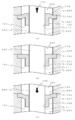
- FIG. 3 is a diagram for explaining the operation of the seal 101 according to the present embodiment. Since the seal 101 is made of an elastic material, when the needle 203 moves upward (reference numeral 131) from the non-operating state (FIG. 3B) (FIG. 3A), or the non-operating state ( When the needle 203 moves downward (reference numeral 132) from FIG. 3B (FIG. 3C), the inner peripheral portion 104 is elastically deformed. By elastically deforming in this way, the through hole side wall 111 and the needle 203 do not slide, and the needle 203 operates together with the main body 102 of the seal 101.
- the seal 101 according to the first embodiment is elastically deformed during the operation of the needle 203, but does not slide, and thus does not generate heat or wear. Thereby, there is little influence on the fluid and the seal 101 itself, no dust is generated, and there is an effect that the life of the parts is extended.
- 2nd Embodiment is related with the seal
- 3rd Embodiment is related with the seal
- 4th Embodiment is related with the seal
- the inner diameter of the lower end face 107 is smaller than the inner diameter of the upper end face 106, so that the needle 203 and the seal 101 can be easily attached and detached.
- the lower end of the seal 101 is tightened more tightly. This can be prevented more than the seal 101 having 103.
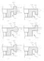
- the fifth embodiment includes an outer peripheral portion 105 having ridges 116 having a rectangular cross section symmetrically toward the upper side and the lower side at the end of the collar portion.
- the sixth embodiment includes an outer peripheral portion 105 having a circular portion 117 having a circular cross section with an outer diameter larger than the thickness of the inner peripheral portion 104 at the end of the collar portion.
- the eighth embodiment includes an outer peripheral portion 105 having a raised portion 119 having a rectangular cross section toward the lower side only at the end portion of the collar portion.
- a protruding portion 120 having a rectangular cross section is provided at the end of the inner peripheral portion 104 only toward the upper side.
- the tenth embodiment includes an outer peripheral portion 105 having a raised portion 119 having a rectangular cross section toward the lower side only at the end portion of the collar portion, and the inner peripheral portion 104 and R are formed at each corner of the outer peripheral portion 105. Since each seal 101 shown in FIG. 5 has a symmetrical shape, only the right half of the seal 101 is shown, and the left half is not shown. Shapes other than those illustrated in the fifth to tenth embodiments may be used, and although not illustrated, they may be, for example, symmetric ellipse, oval, cross, or asymmetric semicircle.
- the shape of the outer peripheral portion 105 is made different from the shape of the inner peripheral portion 104, and correspondingly, the upper and lower housing members (206, 207) are provided with grooves matching the shape, thereby fixing the seal 101. It is easy to do and can be made difficult to come off. Further, the outer peripheral portion 105 is sandwiched and fixed between the upper and lower housing members (206, 207), thereby defining the position of the seal 101 in the fluid chamber 205.
- the eleventh embodiment includes a collar portion (104, 105) provided at an intermediate position between the upper end 121 and the lower end 122 of the main body 102.
- the position of the collars (104, 105) is not limited to the position shown in FIG. May be.
- 6th Embodiment is provided with the collar part (104,105) provided in the lower side edge part 122 of the main-body part 102, as shown in FIG.6 (b).
- the inner peripheral portion 104 is elastically deformed between the main body portion 102 and the outer peripheral portion 105, so that the needle 203 can be moved up and down without sliding with respect to the seal 101.
- the collar portions (104, 105) can be disposed at any position between the upper end portion 121 and the lower end portion 122, but can effectively receive pressure from the fluid filling the fluid chamber 205. From the viewpoint of increasing the sealing force, it is preferable to dispose at a position close to the upper end 121.
- the valve device 201 includes a housing (206, 207) in which a drive chamber 204 for storing the needle drive device 202 and a fluid chamber 205 in which the needle 203 reciprocates are provided. Mainly from the inflow hole 208 to which the fluid is supplied, the outflow hole 209 for discharging the fluid, the valve seat 210 having the outflow hole 209, and the seal 101 that separates the drive chamber 204 and the fluid chamber 205. Configured.
- the drive chamber 204 side may be referred to as the upper side and the fluid chamber 205 side may be referred to as the lower side. Since the seal 101 is the same as that of the first embodiment, description thereof is omitted. In place of the seal 101 of the first embodiment, the seal 101 of the second to twelfth embodiments may be used.
- the housing is composed of an upper housing member 206 and a lower housing member 207.
- a drive chamber 204 for storing a needle drive device 202 for operating the needle 203 is provided on the upper portion of the upper housing member 206.
- a needle 203 is connected to a needle driving device 202 inside a driving chamber 204 not shown in detail.
- the lower portion of the drive chamber 204 is provided with a lower inner wall 212 of the drive chamber so that the needle 203 can operate without sliding contact.
- the needle driving device 202 is an actuator.
- an elastic member spring that urges the compressed gas or the needle 203 in one direction by providing a piston on the side of the driving chamber 204 of the needle 203 to bisect the driving chamber 204.
- the needle 203 is operated using the force of the above, the needle 203 is operated using an electric motor and a ball screw, the needle 203 is operated using an electromagnet, and the needle 203 is operated using a piezoelectric element. Can be used.
- the operation of the needle driving device 202 is controlled by the control device 222.
- a fluid chamber 205 which is a space in which the tip of the needle 203 is disposed, is provided in the direction in which the needle 203 extends (that is, the vertical direction).
- an annular concave portion (expanded diameter portion) surrounded by a circumferential expanded diameter wall 213 is formed in the upper part of the fluid chamber 205.
- the seal 101 and seal pressing members 214a and 214b are disposed in the annular recess.
- a through-hole having a diameter larger than that of the needle 203 is provided at the center of the seal pressing members 214a and 214b made of an annular plate member.
- the seal pressing members 214 a and 214 b may be configured by a single plate-like member. Further, the seal pressing members 214 a and 214 b may be disposed below the seal 101.
- An inflow hole 208 for supplying fluid into the fluid chamber 205 (reference numeral 218) is provided on the side surface of the fluid chamber 205 so as to penetrate the side wall of the lower housing 207.
- a supply pipe 223 is connected to the outside of the inflow hole 208 by a fixing member 217, and the inflow hole 208 and the supply pipe 223 are always in communication.
- the vertical position of the inflow hole 208 is not limited to the position shown in the figure, and may be close to the seal 101 or close to the outflow hole 209 depending on the nature of the fluid to be used and the control mode.
- the angle intersecting with the fluid chamber 205 does not need to be connected at a right angle to the fluid chamber 205 as illustrated in FIG. 7 according to the fluid to be used, and may be connected with an angle such as an acute angle or an obtuse angle.
- a valve seat 210 having an outflow hole 209 that communicates the inside and the outside of the fluid chamber 205 is provided at the lower end of the fluid chamber 205.
- the valve seat 210 is fixed by a valve seat fixing member 220 that is screwed into the lower end portion of the lower housing 207.
- the valve seat fixing member 220 is provided with a valve seat fixing member through hole 221.
- a discharge pipe 224 is connected to the bottom surface of the valve seat 210 so as to communicate with the valve seat fixing member through hole 221 by a fixing member 211.
- the inner diameter of the outflow hole 209 of the valve seat 210 is smaller than the outer diameter of the needle 203. When the hemispherical tip of the needle 203 contacts the valve seat 210, the outflow hole 209 can be closed.
- the shape of the tip of the needle 203 is not limited to the illustrated shape.
- the needle 203 may be a flat surface, a protrusion provided at the center, or a tapered shape.
- the fluid is supplied to the fluid chamber 205 by a pump or the like (not shown), and supplied to the fluid chamber 205 in a state where pressure is applied.
- the pressing force (reference numeral 110) due to the pressure applied to the fluid can be used for fixing the seal 101 to the needle 203, and the drive chamber 204 side It is possible to more reliably prevent fluid from entering.
- the valve device 201 generally operates as follows. As shown in FIG. 7, the needle driving device 202 is operated so that the needle 203 is positioned upward, the tip of the needle 203 is separated from the outflow hole 209 of the valve seat 210, and the outflow hole 209 of the valve seat 210 is opened.
- the fluid (reference numeral 218) supplied from the inflow hole 208 passes through the fluid chamber 205 and is discharged from the outflow hole 209 of the valve seat 210 (reference numeral 219).
- the needle 203 is moved downward by the needle driving device 202, the seal 101 is deformed as shown in FIG.
- valve device 201 can control the flow of fluid by controlling the needle 203 to be operated in either the open state or the closed state by operating the needle 203 with the needle driving device 202. For example, (1) control is normally performed in an open state and closed when necessary, and (2) control is normally performed in a closed state and open when necessary.
- the state shown in FIG. 3C is a closed state and the state shown in FIG. 3B is an open state.
- the positional relationship may be an open state or a closed state.
- FIG. 3B is in a closed state and FIG. 3A is in an open state
- FIG. 3C is in a closed state and FIG. 3A is in an open state.
- FIG. 3B is a no-load state when the movement is stopped, and a state in which the seal 101 is deformed based on the control condition (FIG. 3A ) And (c)) are preferably not maintained for a long time.
- a stroke adjusting mechanism may be provided to limit the stroke.
- the stroke adjustment mechanism is used not only to keep the stroke small, but also to adjust to a desired stroke.
- the stroke adjusting mechanism of the present embodiment is realized by providing a stroke adjusting member 216 that contacts and positions the rear end portion (upper end portion) of the needle 203, but unlike this, an actuator that can accurately perform positioning is used. You may implement
- the needle driving device 202 is configured with an actuator using a compressed gas or a spring force or a type using an electromagnet, the length is adjusted to hit the rear end of the needle 203. It is exemplified that a possible stroke adjusting member is provided in the drive chamber 204.
- the needle 203 does not slide (displace) with respect to the seal 101, heat generation and wear do not occur. For this reason, there is little influence on the fluid and the seal 101 itself, no dust is generated, and the life of the parts is extended.
- the pressing force (symbol 110) by the pressure applied to the fluid can be used for fixing the seal 101 to the needle 203, so that the drive chamber 204 side is reached. It is possible to more reliably prevent the fluid from entering.
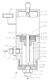
- the discharge device 301 As shown in FIG. 8, the discharge device 301 according to the fourteenth embodiment has a storage container 302 connected to the inlet hole 208 of the valve device 201 of the thirteenth embodiment described above, and a nozzle member at the lower end of the lower housing member 207. 305 is connected. Since the valve device 201 is the same as that in the thirteenth embodiment, the description thereof is omitted and only different portions will be described.
- the storage container 302 is a cylindrical container that stores a fluid therein, and is connected via an extending member 303 that is provided outside the inflow hole 208 and has a channel inside.
- a commercially available syringe can be used for the storage container 302.
- a compressed gas 304 for pumping fluid is supplied from a compressed gas source (not shown).
- a nozzle member 305 through which a tubular member 306 communicating with the outflow hole 209 of the valve seat 210 is provided.
- the nozzle member 305 is fixed to the lower end of the lower housing member 207 (fluid chamber 205) by the nozzle fixing member 307 together with the valve seat 210.
- the nozzle fixing member 307 is detachable to facilitate replacement of the nozzle member 305.
- the lower end opening of the tubular member 306 constitutes a discharge port. That is, the fluid supplied into the fluid chamber 205 is discharged from the outflow hole 209 of the valve seat 210 to the outside through the inside of the tubular member 306.
- the control device 308 controls the needle driving device 202, but in addition, controls the pressure of the compressed gas 304 applied to the storage container 302. Unlike this, a control device for controlling the pressure of the compressed gas 304 applied to the storage container 302 may be separately provided, and the control of the needle driving device 202 may be configured in the same manner as the control device 222 of the thirteenth embodiment.
- the discharge device 301 generally operates as follows.
- the discharge device 301 is closed when the operation is stopped.
- the needle 203 is moved downward by the needle driving device 202, and when the needle 203 moves from the open state to the closed state, the tip of the needle 203 blocks the outflow hole 209 of the valve seat 210 to stop the flow of fluid.
- the discharge from the nozzle member 305 stops.
- the above is a basic one-time discharge operation. In other words, the discharge device 301 discharges the fluid to which the pressure is applied from the tubular member 306 to the outside only during the open time.
- the discharge is performed from the nozzle member 305 by controlling the time during which the valve is open and the magnitude of the pressure applied to the fluid in the storage container 302.
- the amount of fluid can be controlled.
- the liquid can be discharged from the nozzle member 305 in a droplet shape by shortening the opening time (for example, about 1 second or less).
- the pressure of the liquid supplied from the inflow hole 208 may be weakened, and the needle 203 may be advanced at a high speed to stop suddenly, thereby applying an inertial force to the liquid material in the fluid chamber 205 to eject and eject one droplet.
- This discharge method may be referred to as a jet type discharge method.
- the jet-type discharge method includes a seating-type jet-type discharge method in which the tip of the needle 203 abuts against the valve seat 210 when forming one droplet, and the tip of the needle 203 when forming one droplet.
- a non-sitting type jet discharge method that does not contact the valve seat 210, but the seal 101 of the present invention is applicable to any of them.
- a stroke adjusting member may be provided as necessary.
- the seal 101 when the needle 203 is operated, the seal 101 is elastically deformed similarly to the valve device 201 described above, so the needle 203 does not slide (displace) with respect to the seal 101. Does not generate heat or wear. For this reason, there is little influence on the fluid and the seal 101 itself, no dust is generated, and the life of the parts is extended. Further, in addition to the seal restoring force (symbol 109), the pressing force (symbol 110) due to the pressure applied to the fluid can be used to fix the seal 101 to the needle 203, and the force toward the drive chamber 204 can be utilized. The entry of fluid can be prevented more reliably. Furthermore, since the seal 101 is simply clamped and fixed, the needle 203 can be removed without requiring tools or skills, and in addition, the seal 101 can be attached or detached without requiring tools or skills. The load of maintenance work can be greatly reduced.
- the coating apparatus 401 includes a discharge apparatus 301 for discharging a fluid, a stage 402 on which an application target 403 is placed, and a discharge apparatus 301 and a stage 402.
- An XYZ driving device (404, 405, 406) for relative movement and a control device 412 for controlling the operation of each device are mainly configured. Since the discharge device 301 is the same as the discharge device 301 described in the above-described fourteenth embodiment, description thereof is omitted and only different portions will be described.
- the stage 402 is a flat plate-like member having a flat surface on which the application object 403 is placed.
- a mechanism for forming a plurality of holes leading from the inside of the stage 402 to the upper surface and sucking air from the holes to fix the application target object 403 by suction an application target object 403 A mechanism for fixing the coating object 403 can be used by sandwiching the member with a fixing member and fixing the member to the stage 402 with fixing means such as a screw.
- the XYZ driving device includes an X-direction driving device 404, a Y-direction driving device 405, and a Z-direction driving device 406.
- the ejection device 301 is relatively moved with respect to the stage 402 in the X direction (reference numeral 407), the Y direction (reference numeral 408), and the Z direction (reference numeral 409).
- the XYZ driving device is not limited to the above configuration as long as the ejection device 301 and the stage 402 can be relatively moved.
- the discharge device 301 may be moved in the X direction (reference numeral 407) and the Z direction (reference numeral 409), and the stage 402 may be moved in the Y direction (reference numeral 408), or an inverted U shape that straddles the stage 402.
- the discharge device 301 is installed on a frame (also referred to as a portal) so as to be movable in the Z direction (reference 409), and the stage 402 is moved in the X direction (reference 407) and the Y direction (reference 408).
- a frame also referred to as a portal
- the stage 402 is moved in the X direction (reference 407) and the Y direction (reference 408).
- the XYZ driving device a combination of an electric motor (servo motor, stepping motor, etc.) and a ball screw, a linear motor, or the like can be used.
- the control device 412 includes a processing device (not shown), a storage device, an input device, and an output device.
- the above-described ejection device 301 and XYZ driving devices (404, 405, 406) are connected to each other. Control the operation of the device.
- a processing device and the storage device for example, a personal computer (PC), a programmable logic controller (PLC), or the like can be used.
- PLC programmable logic controller
- a touch panel that also serves as an input / output can be used as an input device and an output device.
- the above-described devices are arranged on the top and inside of the gantry 410. It is preferable to cover the upper portion of the gantry 410 on which the above-described ejection device 301, stage 402, and XYZ driving devices (404, 405, 406) are provided with a cover 411 indicated by a dotted line. This prevents dust from entering the inside of the coating device 401, which may cause device failure or product failure, and inadvertent contact between the operator and a movable part such as the XYZ driving device (404, 405, 406). Can be prevented. For convenience of work, a door that can be opened and closed may be provided on the side surface of the cover 411.
- the coating apparatus 401 according to the fifteenth embodiment configured as described above combines various operations (for example, dot, point) by combining the operation of the ejection device 301 and the operation of the XYZ driving devices (404, 405, 406).
- a fluid of a straight line, a curved line, a combination thereof, or the like can be applied to the application object 403.
Landscapes
- Engineering & Computer Science (AREA)
- General Engineering & Computer Science (AREA)
- Mechanical Engineering (AREA)
- Physics & Mathematics (AREA)
- Architecture (AREA)
- Fluid Mechanics (AREA)
- Lift Valve (AREA)
- Sealing Devices (AREA)
- Coating Apparatus (AREA)
- Gasket Seals (AREA)
- Seal Device For Vehicle (AREA)
Priority Applications (7)
| Application Number | Priority Date | Filing Date | Title |
|---|---|---|---|
| KR1020197020700A KR102449612B1 (ko) | 2017-02-24 | 2018-02-22 | 시일 구조 및 상기 시일 구조를 구비하는 장치 |
| MYPI2019004874A MY196551A (en) | 2017-02-24 | 2018-02-22 | Seal Structure, and Device with Said Seal Structure |
| SG11201906854TA SG11201906854TA (en) | 2017-02-24 | 2018-02-22 | Seal structure, and device with said seal structure |
| CN201880013577.2A CN110325772B (zh) | 2017-02-24 | 2018-02-22 | 密封结构及具备该密封结构的装置 |
| EP18758331.5A EP3587866A4 (en) | 2017-02-24 | 2018-02-22 | SEALING STRUCTURE AND DEVICE WITH THIS SEALING STRUCTURE |
| US16/487,296 US11384862B2 (en) | 2017-02-24 | 2018-02-22 | Seal structure, and device with said seal structure |
| PH12019550161A PH12019550161A1 (en) | 2017-02-24 | 2019-08-20 | Seal structure, and device with said seal structure |
Applications Claiming Priority (2)
| Application Number | Priority Date | Filing Date | Title |
|---|---|---|---|
| JP2017032975A JP6793397B2 (ja) | 2017-02-24 | 2017-02-24 | シール構造および該シール構造を備える装置 |
| JP2017-032975 | 2017-02-24 |
Publications (1)
| Publication Number | Publication Date |
|---|---|
| WO2018155580A1 true WO2018155580A1 (ja) | 2018-08-30 |
Family
ID=63252723
Family Applications (1)
| Application Number | Title | Priority Date | Filing Date |
|---|---|---|---|
| PCT/JP2018/006538 WO2018155580A1 (ja) | 2017-02-24 | 2018-02-22 | シール構造および該シール構造を備える装置 |
Country Status (10)
| Country | Link |
|---|---|
| US (1) | US11384862B2 (zh) |
| EP (1) | EP3587866A4 (zh) |
| JP (1) | JP6793397B2 (zh) |
| KR (1) | KR102449612B1 (zh) |
| CN (1) | CN110325772B (zh) |
| MY (1) | MY196551A (zh) |
| PH (1) | PH12019550161A1 (zh) |
| SG (1) | SG11201906854TA (zh) |
| TW (1) | TWI757434B (zh) |
| WO (1) | WO2018155580A1 (zh) |
Families Citing this family (8)
| Publication number | Priority date | Publication date | Assignee | Title |
|---|---|---|---|---|
| JP6778426B2 (ja) * | 2016-09-20 | 2020-11-04 | 武蔵エンジニアリング株式会社 | 液体材料吐出装置 |
| JP7198771B2 (ja) * | 2017-04-21 | 2023-01-04 | ノードソン コーポレーション | 吐出システム |
| ES2906064T3 (es) * | 2019-03-29 | 2022-04-13 | Robatech Ag | Dispositivo para la distribución de un medio capaz de fluir |
| US20210301943A1 (en) * | 2020-03-27 | 2021-09-30 | Illinois Tool Works Inc. | Dispensing unit having fixed flexible diaphragm seal |
| KR102511232B1 (ko) | 2020-11-20 | 2023-03-20 | 농업회사법인 퓨리원 합자회사 | 인삼 재배용 상토 조성물 및 이를 이용한 인삼 재배 방법 |
| CN112431930A (zh) * | 2020-11-23 | 2021-03-02 | 石家庄禾柏生物技术股份有限公司 | 一种密封阀及包含该密封阀的出液结构 |
| TWI807812B (zh) * | 2022-05-06 | 2023-07-01 | 高科晶捷自動化股份有限公司 | 出膠裝置及其出膠方法 |
| CN116146720B (zh) * | 2023-02-17 | 2023-10-20 | 江苏江沅机械有限公司 | 一种安全控制阀门 |
Citations (3)
| Publication number | Priority date | Publication date | Assignee | Title |
|---|---|---|---|---|
| JPH07299402A (ja) | 1994-05-10 | 1995-11-14 | Nireco Corp | ムービングコイル駆動型ニードル弁 |
| JP2008267493A (ja) * | 2007-04-20 | 2008-11-06 | Kyoei Ind Co Ltd | 往復動作する作動軸のシール構造 |
| JP2012055883A (ja) | 2010-09-13 | 2012-03-22 | Nordson Corp | コンフォーマルコーティングアプリケータ及び方法 |
Family Cites Families (11)
| Publication number | Priority date | Publication date | Assignee | Title |
|---|---|---|---|---|
| US2594539A (en) * | 1945-09-08 | 1952-04-29 | Bridgeport Brass Co | Insecticide dispenser |
| US3073490A (en) | 1959-07-06 | 1963-01-15 | Dole Valve Co | Fluid dispensing valve |
| US3255974A (en) * | 1964-08-17 | 1966-06-14 | Hartford Machine Screw Co | Fuel injection nozzle |
| US3722801A (en) * | 1970-09-11 | 1973-03-27 | Stanadyne Inc | Fuel injector |
| JPS514841U (zh) | 1974-06-27 | 1976-01-14 | ||
| JPS52160047U (zh) | 1976-05-28 | 1977-12-05 | ||
| GB2194822A (en) | 1986-09-05 | 1988-03-16 | Grace W R & Co | Dispensing gun seal |
| FR2659115B1 (fr) * | 1990-03-02 | 1992-05-15 | Procal | Joint d'etancheite pour injecteur de moteur a combustion interne. |
| KR100506642B1 (ko) * | 2001-12-19 | 2005-08-05 | 마츠시타 덴끼 산교 가부시키가이샤 | 디스플레이 패널의 패턴 형성방법 및 형성장치 |
| JP4702052B2 (ja) * | 2003-03-31 | 2011-06-15 | 新日本理化株式会社 | 潤滑油及び潤滑方法 |
| US7070066B2 (en) * | 2004-04-08 | 2006-07-04 | Nordson Corporation | Liquid dispensing valve and method with improved stroke length calibration and fluid fittings |
-
2017
- 2017-02-24 JP JP2017032975A patent/JP6793397B2/ja active Active
-
2018
- 2018-02-22 US US16/487,296 patent/US11384862B2/en active Active
- 2018-02-22 KR KR1020197020700A patent/KR102449612B1/ko active IP Right Grant
- 2018-02-22 WO PCT/JP2018/006538 patent/WO2018155580A1/ja active Search and Examination
- 2018-02-22 MY MYPI2019004874A patent/MY196551A/en unknown
- 2018-02-22 SG SG11201906854TA patent/SG11201906854TA/en unknown
- 2018-02-22 EP EP18758331.5A patent/EP3587866A4/en active Pending
- 2018-02-22 CN CN201880013577.2A patent/CN110325772B/zh active Active
- 2018-02-23 TW TW107106194A patent/TWI757434B/zh active
-
2019
- 2019-08-20 PH PH12019550161A patent/PH12019550161A1/en unknown
Patent Citations (3)
| Publication number | Priority date | Publication date | Assignee | Title |
|---|---|---|---|---|
| JPH07299402A (ja) | 1994-05-10 | 1995-11-14 | Nireco Corp | ムービングコイル駆動型ニードル弁 |
| JP2008267493A (ja) * | 2007-04-20 | 2008-11-06 | Kyoei Ind Co Ltd | 往復動作する作動軸のシール構造 |
| JP2012055883A (ja) | 2010-09-13 | 2012-03-22 | Nordson Corp | コンフォーマルコーティングアプリケータ及び方法 |
Also Published As
| Publication number | Publication date |
|---|---|
| MY196551A (en) | 2023-04-19 |
| EP3587866A4 (en) | 2020-12-09 |
| CN110325772A (zh) | 2019-10-11 |
| PH12019550161A1 (en) | 2020-06-08 |
| CN110325772B (zh) | 2022-04-29 |
| JP2018138788A (ja) | 2018-09-06 |
| KR102449612B1 (ko) | 2022-09-29 |
| US20190376617A1 (en) | 2019-12-12 |
| JP6793397B2 (ja) | 2020-12-02 |
| KR20190116265A (ko) | 2019-10-14 |
| TW201839301A (zh) | 2018-11-01 |
| EP3587866A1 (en) | 2020-01-01 |
| US11384862B2 (en) | 2022-07-12 |
| TWI757434B (zh) | 2022-03-11 |
| SG11201906854TA (en) | 2019-08-27 |
Similar Documents
| Publication | Publication Date | Title |
|---|---|---|
| WO2018155580A1 (ja) | シール構造および該シール構造を備える装置 | |
| JP6199553B2 (ja) | 容積式ディスペンサー及び個別量の液体を吐出する方法 | |
| US8757511B2 (en) | Viscous non-contact jetting method and apparatus | |
| EP2764925A1 (en) | Liquid material discharge apparatus and method | |
| KR102559677B1 (ko) | 압전 분사 시스템 및 방법 | |
| JP5114527B2 (ja) | 液体供給装置 | |
| JP5166656B2 (ja) | 液体吐出装置、および、液体吐出方法 | |
| CN209855978U (zh) | 液体供给装置 | |
| JP4668330B2 (ja) | 液体吐出装置 | |
| US6932318B2 (en) | Flow control device | |
| KR101625337B1 (ko) | 고 점성 유체용 스프레이 밸브 | |
| JP6629838B2 (ja) | 液滴吐出装置 | |
| JP2017127791A (ja) | 液体吐出装置 | |
| JP2013053684A (ja) | 流路切換弁およびそれを用いた流動性材料の吐出制御装置 | |
| CN109219485B (zh) | 液体材料吐出装置、其涂布装置及涂布方法 | |
| KR20110077293A (ko) | 스프레이 건 | |
| US20220034698A1 (en) | Metering system and method for controlling a metering system | |
| US10272463B2 (en) | Non-impact jetting dispensing module and method | |
| KR101763121B1 (ko) | 개선된 약액 가압 장치, 및 이를 구비한 약액 공급 장치 | |
| TWI732912B (zh) | 隔膜閥 | |
| JP5232606B2 (ja) | マーキング装置用潤滑油供給装置 | |
| JP2017127838A (ja) | 液体吐出装置 | |
| JP2014031811A (ja) | 液体供給制御弁 | |
| JP2017127839A (ja) | 液体吐出用の吐出ノズル | |
| JP2017127837A (ja) | 液体吐出装置 |
Legal Events
| Date | Code | Title | Description |
|---|---|---|---|
| 121 | Ep: the epo has been informed by wipo that ep was designated in this application |
Ref document number: 18758331 Country of ref document: EP Kind code of ref document: A1 |
|
| DPE1 | Request for preliminary examination filed after expiration of 19th month from priority date (pct application filed from 20040101) | ||
| ENP | Entry into the national phase |
Ref document number: 20197020700 Country of ref document: KR Kind code of ref document: A |
|
| NENP | Non-entry into the national phase |
Ref country code: DE |
|
| ENP | Entry into the national phase |
Ref document number: 2018758331 Country of ref document: EP Effective date: 20190924 |