WO2018150446A1 - 測定装置、測定方法 - Google Patents
測定装置、測定方法 Download PDFInfo
- Publication number
- WO2018150446A1 WO2018150446A1 PCT/JP2017/005250 JP2017005250W WO2018150446A1 WO 2018150446 A1 WO2018150446 A1 WO 2018150446A1 JP 2017005250 W JP2017005250 W JP 2017005250W WO 2018150446 A1 WO2018150446 A1 WO 2018150446A1
- Authority
- WO
- WIPO (PCT)
- Prior art keywords
- component
- measuring
- antistatic
- mover
- measurement
- Prior art date
- Legal status (The legal status is an assumption and is not a legal conclusion. Google has not performed a legal analysis and makes no representation as to the accuracy of the status listed.)
- Ceased
Links
Images




Classifications
-
- H—ELECTRICITY
- H05—ELECTRIC TECHNIQUES NOT OTHERWISE PROVIDED FOR
- H05K—PRINTED CIRCUITS; CASINGS OR CONSTRUCTIONAL DETAILS OF ELECTRIC APPARATUS; MANUFACTURE OF ASSEMBLAGES OF ELECTRICAL COMPONENTS
- H05K13/00—Apparatus or processes specially adapted for manufacturing or adjusting assemblages of electric components
- H05K13/08—Monitoring manufacture of assemblages
- H05K13/082—Integration of non-optical monitoring devices, i.e. using non-optical inspection means, e.g. electrical means, mechanical means or X-rays
-
- G—PHYSICS
- G01—MEASURING; TESTING
- G01R—MEASURING ELECTRIC VARIABLES; MEASURING MAGNETIC VARIABLES
- G01R31/00—Arrangements for testing electric properties; Arrangements for locating electric faults; Arrangements for electrical testing characterised by what is being tested not provided for elsewhere
- G01R31/28—Testing of electronic circuits, e.g. by signal tracer
- G01R31/2801—Testing of printed circuits, backplanes, motherboards, hybrid circuits or carriers for multichip packages [MCP]
- G01R31/2806—Apparatus therefor, e.g. test stations, drivers, analysers, conveyors
- G01R31/2808—Holding, conveying or contacting devices, e.g. test adapters, edge connectors, extender boards
-
- G—PHYSICS
- G01—MEASURING; TESTING
- G01R—MEASURING ELECTRIC VARIABLES; MEASURING MAGNETIC VARIABLES
- G01R31/00—Arrangements for testing electric properties; Arrangements for locating electric faults; Arrangements for electrical testing characterised by what is being tested not provided for elsewhere
- G01R31/28—Testing of electronic circuits, e.g. by signal tracer
- G01R31/2851—Testing of integrated circuits [IC]
- G01R31/2893—Handling, conveying or loading, e.g. belts, boats, vacuum fingers
-
- H—ELECTRICITY
- H05—ELECTRIC TECHNIQUES NOT OTHERWISE PROVIDED FOR
- H05K—PRINTED CIRCUITS; CASINGS OR CONSTRUCTIONAL DETAILS OF ELECTRIC APPARATUS; MANUFACTURE OF ASSEMBLAGES OF ELECTRICAL COMPONENTS
- H05K13/00—Apparatus or processes specially adapted for manufacturing or adjusting assemblages of electric components
- H05K13/04—Mounting of components, e.g. of leadless components
- H05K13/0404—Pick-and-place heads or apparatus, e.g. with jaws
- H05K13/0408—Incorporating a pick-up tool
- H05K13/0409—Sucking devices
Definitions
- the present disclosure relates to a measuring apparatus that measures the electrical characteristics of a component mounted on a circuit board and a method for measuring the electrical characteristics of the component.
- Patent Documents 1 and 2 include a measurement platform including a holding table having a component holding unit for holding a component, and a pair of measuring elements that are provided so as to be able to approach and separate from each other and can measure electrical characteristics with the component interposed therebetween.
- An apparatus is described.
- the component holding part is formed of a conductive material. Therefore, after the part held by the part holding part is gripped by the pair of measuring elements, the part holding part (holding base) is separated from the part, and in this state, the electrical characteristics of the part are measured.
- the components held by the component holding unit are gripped by a pair of measuring elements, and the electrical characteristics are measured.
- Patent Document 2 does not describe a material for forming the component holding portion.
- the problem of the present disclosure is to make it possible to satisfactorily measure the electrical characteristics of a component even if the component is small.
- a measuring apparatus includes a component holding portion and a pair of measuring elements, and at least a part of the component holding portion is formed of a material having antistatic properties (hereinafter referred to as an antistatic material). It is considered as an antistatic part. Since the surface resistance of the antistatic part is large, the electrical characteristics of the part can be measured in a state where the part is held by the antistatic part.
- the measuring apparatus described in Patent Document 1 As described above, after the component is gripped by the pair of measuring elements, the component holding unit is separated from the component. For this reason, if the component is small, the component may scatter and the electrical characteristics may not be measured. On the other hand, in the measuring apparatus according to the present disclosure, it is not necessary to separate the antistatic portion of the component holding unit from the component when measuring the electrical characteristics of the component. Therefore, even if the component is small, it is possible to prevent the component from scattering and to measure the electrical characteristics well. Needless to say, in the measuring apparatus according to the present disclosure, the electrical characteristics can be satisfactorily measured when the parts are large.
- FIG. 9A It is a figure which shows the initial state of the said measuring apparatus.
- FIG. 9B It is a figure which shows the measurement state of the said measuring apparatus.
- FIG. 9C is a diagram showing a discarding state of the measuring device.
- the mounting machine shown in FIG. 1 mounts components on a circuit board, and includes an apparatus main body 2, a circuit board transport and holding device 4, a component supply device 6, a head moving device 8, and the like.
- the circuit board transport and holding device 4 transports and holds a circuit board P (hereinafter abbreviated as “substrate P”).
- substrate P a circuit board P
- the transport direction of the substrate P is the x direction and the width direction of the substrate P is y.
- the direction and the thickness direction of the substrate P are defined as the z direction.
- the y direction and the z direction are the front-rear direction and the vertical direction of the mounting machine, respectively. These x direction, y direction, and z direction are orthogonal to each other.
- the component supply device 6 supplies electronic components (hereinafter abbreviated as components) s to be mounted on the board P, and includes a plurality of tape feeders 14 and the like.
- the head moving device 8 holds the mounting head 16 and moves it in the x, y, and z directions.
- the mounting head 16 has a suction nozzle 18 that sucks and holds the component s.
- Reference numeral 20 denotes a camera.
- the camera 20 images the component s held by the suction nozzle 18 and determines whether the component s is to be mounted on the substrate P based on the image captured by the camera 20. Is done.
- Reference numeral 22 denotes a measuring apparatus.
- the measuring device 22 measures the electrical characteristics of the part s.
- the electrical characteristics of the component s include L (inductance), C (capacitance), R (resistance), Z ′ (impedance), and the like, and one or more of these are measured by the measuring device 22.
- the measuring device 22 is provided in the main body of the circuit board transporting and holding device 4 through the trash box 26.
- the waste bin 26 and the measuring device 22 are connected by a waste passage 28.
- the component s whose electrical characteristics have been measured is accommodated in the trash box 26 via the waste passage 28.
- the measuring device 22 includes: (i) a main body 30; (ii) a measuring table 32 having a component holding portion capable of holding the component s; and (iii) a stator 34 and a mover 36.
- a pair of measuring elements 37 (iv) a measuring table moving apparatus 40 for moving the measuring table 32, (v) a moving element moving apparatus 41 for moving the moving element 36 so as to approach and separate from the stator 34, (vi)
- An LCR detector 42 as an electrical characteristic detector is included.
- the component s has electrode portions at both ends, and can be gripped by a pair of measuring elements 37 at the electrode portions.
- a square chip corresponds to the component s.
- the measuring device 22 is attached to the main body of the circuit board transporting and holding device 4 in a posture in which the moving direction of the movable element 36 and the measuring table 32 corresponds to the y direction.
- an opening 30 a is provided at the bottom of the main body 30.
- the opening 30a is in communication with the waste passage 28.
- the measurement table 32 is held by the measurement table holder 46 so as to be movable integrally.
- the measurement table 32 includes a groove portion 45 formed on the upper surface thereof as a component holding portion.
- the groove portion 45 has a stepped shape extending in the y direction, and a pair of side surfaces extending in the y direction are provided at a first groove portion 45c having a generally V shape and a bottom portion of the first groove portion 45c.
- Of the second groove 45s extending in parallel. The component s is placed and held in the groove 45, but is held in the first groove 45c when the component s is large, and held in the second groove 45s when the component s is small. There are many.
- the measuring table 32 is made of a conductive material (hereinafter referred to as a conductive material), for example, an aluminum alloy or a stainless material, and the like, via a member formed of a plurality of conductive materials.
- a conductive material for example, an aluminum alloy or a stainless material, and the like
- the measurement table 32 is also grounded. That is, the measurement table 32 contacts the measurement table holder 46 and is fixed by the fastening portion 47, and the measurement table holder 46 contacts the main body 30 via the stopper 80 (see FIG. 3).
- the measurement table holder 46, the stopper 80, the main body 30, the fastening portion 47, and the like are formed of a conductive material. Therefore, the measurement table 32 is grounded via the measurement table holder 46, the stopper 80, the fastening portion 47, the main body 30, and the like.
- an antistatic material formed by a material having an antistatic property (hereinafter referred to as an antistatic material) on a portion on the stator 34 side in the y direction around the groove portion 45 of the measuring table 32.
- a portion 48 is provided.
- a static eliminating portion 49 and an antistatic portion 48 which are portions formed of a conductive material, are arranged in the y direction, and the antistatic portion 48 is on the forward side (stator side) of the mover 36. 49 is positioned on the backward side of the movable element 36.
- the surface resistance of the static elimination part 49 is very small. Therefore, it is possible to remove the charge of the component s by holding the component in the charge removal unit 49.
- the surface resistance of the antistatic portion 48 is between 10 9 ⁇ and 10 13 ⁇ .
- the antistatic material is a composite material composed of a plurality of materials, for example, a product manufactured by kneading an antistatic agent in a resin, a product manufactured by applying an antistatic agent to the surface of the resin, and the like.
- Antistatic agents are well known and include, for example, “Pelestat (registered trademark)” manufactured by Sanyo Chemical Industries, Ltd.
- the antistatic material has a surface resistance smaller than that of the insulating material, if the energization time to the component s is increased, a current also flows through the antistatic portion 48, and the electrical characteristics of the component may not be detected accurately. However, since the time required for measuring the electrical characteristics of the component s is short, there is no problem. Further, as described above, since the antistatic material has a surface resistance smaller than that of the insulating material, the antistatic portion 48 hardly generates static electricity and is difficult to be charged. Therefore, even if friction occurs in the antistatic portion 48 due to the movement of the component s, the generation of static electricity is suppressed and charging is prevented.
- the surface resistance of the antistatic material is larger than that of the conductive material and smaller than that of the insulating material. Therefore, the antistatic material has characteristics that it is difficult for electricity to flow and it is difficult to be charged. This characteristic makes it possible to measure the electrical characteristics of the component s in a state where the component s is held by the antistatic portion 48, and to produce a specific effect that the electrical characteristics can be measured with high accuracy. It is.
- the cover unit 50 is attached to the stator 34 side of the measurement table 32. As will be described later, the cover portion 50 prevents air from diffusing and prevents the parts s that have fallen due to the ejection of air from being scattered.
- the cover part 50 includes a pair of cover plate parts 52 and 54 provided on both sides of the groove part 45, respectively, separated from each other in the x direction.
- the cover plate portions 52 and 54 extend in the y direction and the z direction, that is, in the moving direction and the vertical direction of the measuring table 32 and the mover 36, respectively.
- the stator 34 and the mover 36 are provided so as to be able to approach and separate from each other.
- the stator 34 is fixed to the main body 30 via a stator holder 55.
- the mover 36 is held by a mover holding body 56 at one end (reverse side end), and can move integrally with the mover holding body 56.
- an engaging portion 36 a that can engage with the groove portion 45 of the measuring table 32 is provided at the other end portion (the end portion on the forward side) of the mover 36.
- the engaging portion 36 a has a stepped shape corresponding to the groove portion 45.
- the engaging portion 36a is provided with a first engaging portion 36c that extends downward and protrudes in a triangular shape, and a second engaging portion that protrudes further downward from the vicinity of the top of the first engaging portion 36c and has a quadrangular cross section. And a joining portion 36s.
- the first engaging part 36c engages with the first groove part 45c
- the second engaging part 36s engages with the second groove part 45s.
- at least a part of the engaging portion 36a is always engaged with the groove 45. Therefore, the gap between the engaging portion 36a and the groove portion 45 can be made very small.
- the stator 34 and the movable element 36 constitute a pair of measuring elements 37.
- the stator 34 and the mover 36 have opposing surfaces 34f and 36f that face each other, and the component s is gripped by the pair of opposing surfaces 34f and 36f. That is, the component s, the pair of measuring elements 37, the LCR detection unit 42, the power supply device not shown in the figure, and the like in a state where the electrode portions at both ends of the component s and the pair of measuring elements 37 are in contact with each other.
- An electrical circuit 58 is formed. While a voltage is applied between the stator 34 and the mover 36, a current flowing between them is detected by the LCR detector 42, and based on the applied voltage, the flowing current, etc.
- the electrical characteristics of the part s are acquired.
- the LCR detection unit 42 is not limited to a detection unit that detects L, C, and R, and can detect one or more physical quantities representing electrical characteristics such as L, C, R, and Z ′.
- Reference numerals 58a and 58b in FIGS. 2 and 3 are connecting portions of the pair of measuring elements 37 to the electric circuit 58.
- the measurement device 22 includes an air supply device 59.
- the air supply device 59 includes an air passage 60, an ionizer 62, an air source 68, and the like.
- the air passage 60 includes an internal passage 60h formed in the stator holding body 55, the main body 30, and the like, an air ejection passage 60s formed in the stator 34, and the like.
- the air ejection passage 60s extends in the y direction so as to incline downward toward the mover 36, and the opening 60a faces the facing surface 36f of the mover 36.
- the extension line K of the air ejection passage 60s is a portion (gripping part) R where the frequency of gripping the part s on the facing surface 36f of the mover 36 is high when the mover 36 is located away from the stator 34. Reach slightly above.
- the air supplied through the air ejection passage 60s strikes the facing surface 36f from obliquely above.
- An air source 68 and the like are connected to the air passage 60 via an ionizer 62.
- the ionizer 62 ionizes air by causing corona discharge, and supplies the ionized air.
- the measuring table moving device 40 moves the measuring table 32 and includes an air cylinder 64 as a drive source. As shown in FIG. 6, in the air cylinder 64, the interior of the housing is partitioned into two air chambers 64 a and 64 b by a piston, and the measurement table holder 46 is connected to the piston rod 66 of the piston.
- An electromagnetic valve device 69 is provided between the two air chambers 64a and 64b, the air source 68, the air passage 60, and the filter (atmosphere).
- the electromagnetic valve device 69 includes a plurality of electromagnetic valves, and the measurement table 32 is moved forward and backward by the control of the electromagnetic valve device 69. When the measuring table 32 moves forward, the air source 68 is communicated with the air chamber 64b, and the air passage 60 is communicated with the air chamber 64a. Therefore, air is supplied from the air chamber 64 a to the air passage 60 as the measurement table 32 advances.
- the mover moving device 41 moves the mover 36 and includes an air cylinder 70 as a drive source.
- an air source 68, an air passage 60, and a filter (atmosphere) are connected to the two air chambers 70a and 70b via an electromagnetic valve device 72.
- the mover 36 is moved forward and backward by the control of the electromagnetic valve device 72.
- the air source is communicated with the air chamber 70a, and the air passage 60 is communicated with the air chamber 70b. Therefore, air is supplied from the air chamber 70 b to the air passage 60 as the mover 36 moves backward.
- the air cylinders 64 and 70 also have a function as an air source of the air supply device 59.
- a pair of guide rods 74 and 75 extending in the y direction are provided between the main body 30 or the stator holder 55 and the mover holder 56, and the measurement table 32 and the mover holder are provided.
- a pair of guide rods 76 and 77 extending in the y direction are provided between the body 56 and the body 56. These guide rods 74, 75, 76, 77 allow the stator 34 and the mover 36 to move relative to each other in the y direction, and allow the measuring table 32 and the mover 36 to move relative to each other in the y direction.
- a stopper 82 is provided on the stator side of the mover holder 56, and a stopper 80 is provided on the main body 30 or the stator holder 55.
- the stopper 82 defines the approach limit between the movable element holder 56 and the measurement table 32 (measurement table holder 46), and the stopper 80 includes the stator 34 and the measurement table 32 (measurement table holder 46). This regulates the approach limit.
- the mounting machine includes a control device 100.
- the control device 100 includes a controller 102 mainly composed of a computer and a plurality of drive circuits 104.
- the controller 102 includes an execution unit 110, a storage unit 112, an input / output unit 114, and the like.
- the substrate transfer holding device 4, the component supply device 6, and the head moving device 8 each include a drive circuit 104.
- the electromagnetic valve devices 69 and 72 of the measuring table moving device 40 and the mover moving device 41 are connected.
- an LCR detection unit 42, a display 116, a mover position sensor 118, a measurement stand position sensor 120, a nozzle height sensor 122 for detecting the height of the nozzle 18, and the like are connected.
- the storage unit 112 stores a plurality of programs and tables such as the LCR measurement program represented by the flowchart of FIG. Further, time is measured by a timer 124 provided in the controller 102.
- the electromagnetic valve devices 69 and 72 are controlled by using the outputs of the measurement table position sensor 120 and the mover position sensor 118, the measurement time by the timer 124, etc., and the measurement table 32 and the mover 36 move forward. , Retreated.
- the operation of the mounting machine will be described.
- a command for measuring the electrical characteristics of the part s is issued, such as when a new tape feeder 14 is set or the tape feeder 14 is replaced, the electrical of the part s held by the tape feeder 14 is output. Characteristics are measured.
- a measured value that is a value of the measured electrical characteristic may be compared with a standard value of the component, and it may be determined whether or not these values substantially match. In that case, the result of comparing the measured value with the standard value can be displayed on the display 116.
- the electrical characteristics of the component s are measured by executing the LCR measurement program represented by the flowchart of FIG.
- the measuring device 22 In the non-operating state of the mounting machine, the measuring device 22 is in the initial state shown in FIG. 9A.
- the mover 36 is in the retracted end position, and the measuring table 32 is in the advanced end position. Since the measurement table 32 is in contact with the stopper 80, the charge removal unit 49 is grounded due to internal conduction or the like. Further, the neutralizing portion 49 of the groove portion 45 of the measuring table 32 is in a state where the engaging portion 36a of the movable element 36 is engaged.
- step 1 it is determined whether or not a measurement command for the electrical characteristics of the component s has been issued.
- the mounting head 16 is moved in S2, for example, the component s held by the newly attached tape feeder 14 is picked up by the suction nozzle 18, and the static elimination unit 49 It is placed and held in front of the facing surface 36f of the mover 36. It can be seen that the suction nozzle 18 is lowered and the component s is opened, so that the component s is held by the charge removal unit 49.
- the component s is large, it is held in the first groove 45c, and when the component s is small, it is held in the second groove 45s.
- the elapsed time after the component s is held by the static elimination unit 49 is measured, and it is waited for the static elimination time that is the set time to elapse.
- Each of the parts s held by the tape feeder 14 is in a state of being charged by static electricity generated due to vibration accompanying transportation of the tape feeder 14, contact with an object, or the like.
- the charged component s is neutralized by being held by the neutralization unit 49.
- the static elimination time is the time required to remove the static electricity of the capacity estimated to be possessed by the part s, and is obtained in advance by experiments or theoretically based on the size, characteristics, etc. of the part s. You can do it.
- the advancement of the mover 36 is started under the control of the electromagnetic valve device 72 in S4.
- the engaging portion 36a of the mover 36 is advanced along the groove portion 45 of the measuring table 32, and when the facing surface 36f contacts the component s, the component s is charged from the charge removal portion 49 by the advance of the mover 36. It is moved to the prevention unit 48.
- the mover 36 is moved forward after the suction nozzle 18 reaches the rising end.
- S ⁇ b> 5 the component s is clamped by the opposing surface 36 f of the movable element 36 and the opposing surface 34 f of the stator 34 at the electrode portions at both ends in the antistatic portion 48.
- the electrical characteristics of the component s are measured while being held by the antistatic portion 48.
- This state is the measurement state shown in FIG. 9B.
- the length L1 in the y direction of the engaging portion 36a of the mover 36 is shorter than the length L2 of the antistatic portion 48 (L1 ⁇ L2).
- the engaging portion 36a is located at a position separated from the static eliminating portion 49. Therefore, when current is supplied to the pair of measuring elements 37, current leakage through the static elimination section 49 can be satisfactorily prevented, and the electrical characteristics of the component s can be accurately measured.
- the movable element 36 is retracted by the control of the electromagnetic valve devices 72 and 69, and is retracted until the measuring table 32 comes into contact with the stopper 82.
- the front end surface of the measurement table 32 is located substantially the same as or slightly behind the opposed surface 36f of the mover 36, and there is no measurement table 32 below the pair of opposed surfaces 34f and 36f. .
- This state is a discarding state. The part s falls downward and is accommodated in the trash box 26 through the opening 30a and the disposal passage 28.
- the cover 50 covers the space between the pair of opposing surfaces 34f and 36f from the x direction. As a result, the component s can be further dropped from the facing surface 36f, and scattering of the component s can be prevented.
- the measurement table 32 is advanced to the forward end position by the control of the electromagnetic valve device 69, and is set to the initial state shown in FIG. 9A. Further, when the measuring table 32 moves forward, air is supplied from the opening 60a of the air ejection passage 60s to the facing surface 36f of the mover 36. For this reason, it is possible to satisfactorily eliminate the charge on the facing surface 36f of the mover 36. Further, as shown in FIGS. 9A to 9C, in this embodiment, the groove 45 of the measuring table 32 and at least a part of the engaging portion 36a of the movable element 36 are always engaged. Therefore, the gap between the engaging part 36a and the groove part 45 can be reduced, and even if the part s is small, the biting of the part s can be suppressed satisfactorily.
- the electrical characteristics of the component s are measured in a state where the component s is held by the antistatic portion 48. Therefore, even if the component s is small, it is possible to measure the electrical characteristics while preventing the component s from scattering. Further, the electrical characteristics are measured after the component s is held by the static elimination unit 49 and neutralized. As a result, it is possible to accurately measure the electrical characteristics of the component s.
- execution of S3 corresponds to the static elimination process
- execution of S4 corresponds to the movement process
- S5 corresponds to the measurement process
- execution of S6 corresponds to the disposal process.
- step S3 is not indispensable. If the static elimination time is very short, it can be ignored. Further, even when the static elimination time elapses until the suction nozzle 18 reaches the rising end, the step of S3 is substantially unnecessary. This is because the mover 36 is advanced after the suction nozzle 18 reaches the rising end.
- the movable table 36 may be retracted after the movable table 36 is retracted, or the movable table 36 and the measuring table 32 may be retracted almost simultaneously.
- the length L1 of the engaging part 36a is 80% or less, 70% or less, 60% or less, 50% or less, 40% or less, 30% or less, 20% or less, etc. of the length L2 of the antistatic part 48.
- the present disclosure can be implemented in various modifications and improvements based on the knowledge of those skilled in the art.
- Measuring device 30 Main body 30a: Opening 32: Measuring table 34: Stator 36: Movable member 36a: Engaging portion 34f, 36f: Opposing surface 40: Measuring table moving device 41: Movable member moving device 42: LCR detection unit 45: Groove part 45c: First groove part 45s: Second groove part 48: Antistatic part 49: Static elimination part 100: Control device
- a component holding unit for holding the component; Including a pair of measuring elements that are provided so as to be able to approach and separate from each other and sandwich the part held by the part holding part and measure the electrical characteristics of the part;
- a measuring apparatus in which the component holding unit includes a static eliminating unit formed of a conductive material and an antistatic unit formed of a material having antistatic properties.
- the antistatic part used in the measuring apparatus described in this section has characteristics that it is difficult for current to flow and it is difficult to be charged. In other words, even when a current is supplied to the component while the component is held by the antistatic portion, it is difficult for the current to flow through the antistatic portion and even if friction occurs with the component, it is difficult to be charged. It can have a surface resistance of a degree.
- the antistatic part may have a surface resistance between 10 9 ⁇ and 10 12 ⁇ .
- the pair of measuring elements includes a stator and a movable element, Item (1) or (2), wherein the antistatic portion and the static elimination portion are provided along the moving direction of the mover, and the antistatic portion is positioned on the forward side of the mover from the static elimination portion.
- the mover has an engaging portion that can be engaged with the component holding portion,
- the movable element and the component holding part are configured in a state where at least a part of the engaging part is engaged with the component holding part even when the movable element is in the retracted end position (3).
- the measuring device described in 1. At least a part of the engaging portion of the mover is always engaged with the component engaging portion. Therefore, the gap between the mover and the component engaging portion can be reduced.
- the measurement apparatus includes a holding table including the component holding unit, The measuring device according to any one of (1) to (5), wherein the component holding portion is provided on an upper surface of the holding base and is a groove portion parallel to a relative movement direction of the pair of measuring elements. .
- the groove portion includes a first groove portion having a pair of side surfaces generally V-shaped, and a second groove portion provided at a bottom portion of the first groove portion and the pair of side surfaces extending in parallel with each other.
- the measuring device described in 1. By using a stepped groove as the component holding portion, it is possible to hold the component well regardless of whether the component is large or small.
- the measurement device detects an electric current flowing between the pair of measuring elements in a state where a voltage is applied between the pair of measuring elements, and acquires the electrical characteristics of the component
- the measuring apparatus according to any one of (1) to (7), including a physical characteristic acquisition unit.
- a measuring method for measuring electrical characteristics of the component in the measuring device according to any one of (3) to (8), A moving step of moving the component held in front of the mover of the static eliminator of the component holding unit to the antistatic unit by advancement of the mover; A measuring method including a measuring step in which the pair of measuring elements grips the component in the antistatic part and measures the electrical characteristics of the component.
- the measurement apparatus includes a measurement table provided with the component holder.
Landscapes
- Engineering & Computer Science (AREA)
- Microelectronics & Electronic Packaging (AREA)
- Manufacturing & Machinery (AREA)
- Computer Hardware Design (AREA)
- General Engineering & Computer Science (AREA)
- Physics & Mathematics (AREA)
- General Physics & Mathematics (AREA)
- Operations Research (AREA)
- Supply And Installment Of Electrical Components (AREA)
- Testing Electric Properties And Detecting Electric Faults (AREA)
- Testing Of Individual Semiconductor Devices (AREA)
Abstract
測定装置において、仮に、部品が小さくても、電気的特性を良好に測定可能とすることである。 本測定装置においては、部品保持部の少なくとも一部が帯電防止材で形成された帯電防止部とされる。帯電防止部の表面抵抗は大きいため、部品が帯電防止部によって保持された状態で、その部品の電気的特性を測定することができる。その結果、仮に、部品が小さくても、部品の飛散を防止し、電気的特性を良好に測定することができる。
Description
本開示は、回路基板に装着される部品の電気的特性の測定を行う測定装置、部品の電気的特性の測定方法に関するものである。
特許文献1,2には、部品を保持する部品保持部を備えた保持台と、互いに接近・離間可能に設けられ、部品を挟んで電気的特性を測定可能な一対の測定子とを含む測定装置が記載されている。そのうちの特許文献1に記載の測定装置においては、部品保持部が、導電性を有する材料で形成されたものである。そのため、部品保持部に保持された部品が一対の測定子によって把持された後に、部品保持部(保持台)が部品から離間させられ、その状態で、部品の電気的特性が測定される。特許文献2に記載の測定装置においては、部品保持部に保持された部品が一対の測定子によって把持されて、電気的特性が測定される。特許文献2には、部品保持部を形成する材料についての記載はない。
本開示の課題は、仮に、部品が小さい場合であっても、部品の電気的特性を良好に測定可能とすることである。
本開示に係る測定装置は、部品保持部と、一対の測定子とを含むものであり、部品保持部の少なくとも一部が帯電防止性を有する材料(以下、帯電防止材と称する)で形成された帯電防止部とされる。帯電防止部の表面抵抗は大きいため、部品が帯電防止部によって保持された状態で、部品の電気的特性を測定することができる。
一方、特許文献1に記載の測定装置においては、上述のように、部品が一対の測定子によって把持された後に、部品保持部が部品から離間させられる。そのため、仮に、部品が小さい場合には、部品が飛散し、電気的特性を測定することができない場合があった。それに対して、本開示に係る測定装置においては、部品の電気的特性を測定する際に、部品から部品保持部の帯電防止部を離間させる必要がない。そのため、仮に、部品が小さい場合であっても、部品の飛散を防止し、電気的特性を良好に測定することができる。なお、本開示に係る測定装置においては、部品が大きい場合に電気的特性を良好に測定できることは言うまでもない。
以下、本開示の一実施形態である測定装置を含む装着機について図面に基づいて詳細に説明する。本測定装置においては、本開示の一実施形態である測定方法が実施される。
図1に示す装着機は、部品を回路基板に装着するものであり、装置本体2,回路基板搬送保持装置4,部品供給装置6,ヘッド移動装置8等を含む。
回路基板搬送保持装置4は、回路基板P(以下、基板Pと略称する)を搬送して保持するものであり、図1において、基板Pの搬送方向をx方向、基板Pの幅方向をy方向、基板Pの厚み方向をz方向とする。y方向、z方向は、それぞれ、装着機の前後方向、上下方向である。これら、x方向、y方向、z方向は互いに直交する。部品供給装置6は、基板Pに装着される電子部品(以下、部品と略称する)sを供給するものであり、複数のテープフィーダ14等を含む。ヘッド移動装置8は、装着ヘッド16を保持してx、y、z方向へ移動させるものであり、装着ヘッド16は、部品sを吸着して保持する吸着ノズル18を有する。
図1に示す装着機は、部品を回路基板に装着するものであり、装置本体2,回路基板搬送保持装置4,部品供給装置6,ヘッド移動装置8等を含む。
回路基板搬送保持装置4は、回路基板P(以下、基板Pと略称する)を搬送して保持するものであり、図1において、基板Pの搬送方向をx方向、基板Pの幅方向をy方向、基板Pの厚み方向をz方向とする。y方向、z方向は、それぞれ、装着機の前後方向、上下方向である。これら、x方向、y方向、z方向は互いに直交する。部品供給装置6は、基板Pに装着される電子部品(以下、部品と略称する)sを供給するものであり、複数のテープフィーダ14等を含む。ヘッド移動装置8は、装着ヘッド16を保持してx、y、z方向へ移動させるものであり、装着ヘッド16は、部品sを吸着して保持する吸着ノズル18を有する。
また、符号20はカメラを示す。カメラ20は、吸着ノズル18によって保持された部品sを撮像するものであり、カメラ20によって撮像された画像に基づいて、部品sが基板Pに装着される予定のものであるか否かが判定される。符号22は測定装置を示す。測定装置22は、部品sの電気的特性を測定するものである。部品sの電気的特性としては、L(インダクタンス)、C(キャパシタンス)、R(レジスタンス)、Z′(インピーダンス)等が該当し、測定装置22によってこれらのうちの1つ以上が測定される。
測定装置22は、ごみ箱26を介して回路基板搬送保持装置4の本体に設けられる。ごみ箱26と測定装置22とは廃棄通路28によって接続される。電気的特性が測定された部品sが、廃棄通路28を経てごみ箱26に収容される。
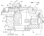
測定装置22は、図2~6に示すように、(i)本体30、(ii)部品sを保持可能な部品保持部を備えた測定台32、(iii)固定子34および可動子36から成る一対の測定子37、(iv)測定台32を移動させる測定台移動装置40、(v)可動子36を移動させて、固定子34に接近・離間させる可動子移動装置41、(vi)電気的特性検出部としてのLCR検出部42等を含む。本実施例において、部品sは、両端に電極部を有し、電極部において一対の測定子37によって把持可能なものである。部品sとしては、例えば、角チップが該当する。図2,3等に記載のように、測定装置22は、可動子36、測定台32の移動方向がy方向に対応する姿勢で回路基板搬送保持装置4の本体に取り付けられる。
本体30の底部には、図3に示すように、開口30aが設けられる。開口30aは、廃棄通路28と連通状態にある。
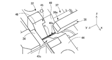
測定台32は、測定台保持体46に、一体的に移動可能に保持される。測定台32は、それの上面に形成された、部品保持部としての溝部45を含む。溝部45は、y方向に伸びた段付き形状を成し、y方向に伸びた一対の側面が、概してV字形を成した第1溝部45cと、その第1溝部45cの底部に設けられ、一対の側面が平行に伸びた第2溝部45sとを含む。溝部45に部品sが載せられて、保持されるのであるが、部品sが大きい場合には、第1溝部45cに保持され、部品sが小さい場合には、第2溝部45sに保持されることが多い。
測定台32は、大部分が、導電性を有する材料(以下、導電材と称する)、例えば、アルミニウム合金またはステンレス材料等によって製造されたものであり、複数の導電材で形成された部材を介して本体30に電気的に接続される(内部導通と称する場合がある)。また、本体30は接地(アース)されているため、測定台32も接地される。すなわち、測定台32が測定台保持体46に当接し、かつ、締結部47によって固定されるとともに、測定台保持体46が本体30にストッパ80(図3参照)を介して当接する。そして、測定台保持体46、ストッパ80、本体30、締結部47等は導電材で形成されたものである。したがって、測定台32は、測定台保持体46、ストッパ80、締結部47、本体30等を経て接地されるのである。
また、図4に示すように、測定台32の溝部45の周辺のy方向における固定子34側の部分には帯電防止性を有する材料(以下、帯電防止材と称する)によって形成された帯電防止部48が設けられる。溝部45には、y方向に、導電材によって形成された部分である除電部49と帯電防止部48とが並んで、帯電防止部48が可動子36の前進側(固定子側)に除電部49が可動子36の後退側に位置することになる。
除電部49の表面抵抗は非常に小さい。そのため、除電部49に部品を保持させることにより、部品sの除電を行うことができる。
帯電防止部48の表面抵抗は109Ω~1013Ωの間の大きさである。帯電防止材は、複数の材料から成る複合材であり、例えば、樹脂に帯電防止剤を混練して製造された物、樹脂の表面に帯電防止剤を塗布して製造された物等が該当する。帯電防止剤はよく知られたものであり、例えば、三洋化成工業株式会社製の商品名「ペレスタット(登録商標)」等がある。
このように、帯電防止部48の表面抵抗は大きいため、帯電防止部48には電流が流れ難い。そのため、部品sが帯電防止部48によって保持された状態で、部品sの電気的特性を測定することができる。一方、帯電防止材は、絶縁材より表面抵抗が小さいため、部品sへの通電時間が長くなると、帯電防止部48にも電流が流れ、部品の電気的特性を正確に検出できない場合もある。しかし、部品sの電気的特性を測定するために要する時間は短いため、差し支えない。
また、上述のように、帯電防止材は絶縁材より表面抵抗が小さいため、帯電防止部48においては、静電気が発生し難く、帯電し難い。そのため、部品sの移動等に起因して、帯電防止部48に摩擦が生じても、静電気の発生が抑制され、帯電が防止される。
以上のように、帯電防止材の表面抵抗は、導電材より大きく、絶縁材より小さい。そのため、帯電防止材は、電気が流れ難く、帯電し難いという特性を有する。この特性により、部品sが帯電防止部48によって保持された状態で部品sの電気的特性を測定することが可能となり、しかも、電気的特性を精度よく測定できるという特有の効果を奏することができるのである。
このように、帯電防止部48の表面抵抗は大きいため、帯電防止部48には電流が流れ難い。そのため、部品sが帯電防止部48によって保持された状態で、部品sの電気的特性を測定することができる。一方、帯電防止材は、絶縁材より表面抵抗が小さいため、部品sへの通電時間が長くなると、帯電防止部48にも電流が流れ、部品の電気的特性を正確に検出できない場合もある。しかし、部品sの電気的特性を測定するために要する時間は短いため、差し支えない。
また、上述のように、帯電防止材は絶縁材より表面抵抗が小さいため、帯電防止部48においては、静電気が発生し難く、帯電し難い。そのため、部品sの移動等に起因して、帯電防止部48に摩擦が生じても、静電気の発生が抑制され、帯電が防止される。
以上のように、帯電防止材の表面抵抗は、導電材より大きく、絶縁材より小さい。そのため、帯電防止材は、電気が流れ難く、帯電し難いという特性を有する。この特性により、部品sが帯電防止部48によって保持された状態で部品sの電気的特性を測定することが可能となり、しかも、電気的特性を精度よく測定できるという特有の効果を奏することができるのである。
測定台32の固定子34側にはカバー部50が取り付けられる。カバー部50は、後述するように、エアの拡散を防止するとともに、エアの噴出によって落下した部品sの飛散を防止するものである。カバー部50は、互いにx方向に隔たって、溝部45の両側にそれぞれ設けられた一対のカバー用板部52,54を含む。カバー用板部52,54は、それぞれ、y方向およびz方向、すなわち、測定台32、可動子36の移動方向および上下方向に伸びたものである。
固定子34、可動子36は、互いに接近・離間可能に設けられる。固定子34は固定子保持体55を介して本体30に固定される。可動子36は一端部(後退側の端部)において可動子保持体56に保持され、可動子保持体56と一体的に移動可能とされる。
また、図3に示すように、可動子36の他端部(前進側の端部)には、測定台32の溝部45に係合可能な係合部36aが設けられる。係合部36aは、図5に示すように、溝部45に対応する段付き形状とされている。係合部36aは、下方に三角形状に突出して伸びた第1係合部36cと、第1係合部36cの頂部付近からさらに下方に突出して設けられ、断面が四角形を成した第2係合部36sとを有する。第1係合部36cが第1溝部45cに係合し、第2係合部36sが第2溝部45sに係合する。また、本実施例においては、係合部36aの少なくとも一部が、常時、溝部45に係合した状態にある。そのため、係合部36aと溝部45との間の隙間を非常に小さくすることができる。
これら固定子34と可動子36とにより一対の測定子37が構成される。固定子34、可動子36は、それぞれ、互いに対向する対向面34f、36fを有し、これら一対の対向面34f、36fによって部品sが把持される。すなわち、部品sの両端の電極部と一対の測定子37とが接触した状態(通電可能な状態)で、部品s、一対の測定子37、LCR検出部42、図示を省略する電源装置等を含む電気回路58が形成される。これら固定子34と可動子36との間に電圧が印加された状態で、これらの間を流れる電流がLCR検出部42によって検出されるとともに、印加された電圧、流れた電流等に基づいて、部品sの電気的特性が取得される。LCR検出部42は、L,C,Rを検出する検出部に限らず、L,C,R,Z´等の電気的特性を表す物理量の1つ以上を検出するものとすることができる。なお、図2,3の符号58a、bは、一対の測定子37の電気回路58への接続部である。
本測定装置22はエア供給装置59を含む。エア供給装置59は、図3に示すように、エア通路60、イオナイザ62、エア源68等を含む。エア通路60は、固定子保持体55および本体30等に形成された内部通路60h、固定子34に形成されたエア噴出通路60s等を含む。エア噴出通路60sは、概してy方向に、可動子36に近づくにつれて下方へいく向きに傾斜して伸び、開口60aは可動子36の対向面36fに対向する。また、エア噴出通路60sの延長線Kは、可動子36が固定子34から離間した位置にある場合に、可動子36の対向面36fの部品sを把持する頻度が高い部分(把持部)Rのやや上方に達する。エア噴出通路60sを経て供給されたエアは、対向面36fに斜め上方から当たる。
エア通路60には、イオナイザ62を介してエア源68等が接続される。イオナイザ62は、コロナ放電を生起させてエアをイオン化するものであり、エアをイオン化して供給する。
エア通路60には、イオナイザ62を介してエア源68等が接続される。イオナイザ62は、コロナ放電を生起させてエアをイオン化するものであり、エアをイオン化して供給する。
測定台移動装置40は、測定台32を移動させるものであり、駆動源としてのエアシリンダ64を含む。図6に示すように、エアシリンダ64において、ハウジングの内部がピストンによって2つのエア室64a、64bに仕切られ、ピストンのピストンロッド66に測定台保持体46が連結される。2つのエア室64a、64bと、エア源68、エア通路60、フィルタ(大気)との間には電磁弁装置69が設けられる。電磁弁装置69は、複数の電磁弁を含むものであり、電磁弁装置69の制御により、測定台32が前進、後退させられる。なお、測定台32の前進時には、エア室64bにエア源68が連通させられ、エア室64aにエア通路60が連通させられる。そのため、測定台32の前進に伴って、エア室64aからエア通路60にエアが供給される。
可動子移動装置41は、可動子36を移動させるものであり、駆動源としてのエアシリンダ70を含む。エアシリンダ70においても同様に、ハウジングの内部には、ピストンによって仕切られた2つのエア室70a、70bが形成され、ピストンのピストンロッド71に可動子保持体56が連結される。2つのエア室70a、70bには、電磁弁装置72を介して、エア源68、エア通路60、フィルタ(大気)が接続される。電磁弁装置72の制御により、可動子36が前進、後退させられる。なお、可動子36の後退時には、エア室70aにエア源が、エア室70bにエア通路60が、それぞれ、連通させられる。そのため、可動子36の後退に伴ってエア室70bからエア通路60にエアが供給される。
以上のことから、エアシリンダ64,70は、エア供給装置59のエア源としての機能も有する。
以上のことから、エアシリンダ64,70は、エア供給装置59のエア源としての機能も有する。
図2に示すように、本体30または固定子保持体55と可動子保持体56との間には、y方向に伸びた一対のガイドロッド74,75が設けられ、測定台32と可動子保持体56との間には、y方向に伸びた一対のガイドロッド76,77が設けられる。これらガイドロッド74,75、76,77により固定子34と可動子36とがy方向に互いに相対移動可能とされるとともに、測定台32と可動子36とは互いにy方向に相対移動可能とされる。
また、図3に示すように、可動子保持体56の固定子側にはストッパ82が設けられ、本体30または固定子保持体55にはストッパ80が設けられる。ストッパ82は、可動子保持体56と測定台32(測定台保持体46)との接近限度を規定するものであり、ストッパ80は、固定子34と測定台32(測定台保持体46)との接近限度を規定するものである。
また、図3に示すように、可動子保持体56の固定子側にはストッパ82が設けられ、本体30または固定子保持体55にはストッパ80が設けられる。ストッパ82は、可動子保持体56と測定台32(測定台保持体46)との接近限度を規定するものであり、ストッパ80は、固定子34と測定台32(測定台保持体46)との接近限度を規定するものである。
当該装着機は制御装置100を含む。制御装置100は、図7に示すように、コンピュータを主体とするコントローラ102と、複数の駆動回路104とを含む。コントローラ102は、実行部110、記憶部112、入出力部114等を含み、入出力部114には、基板搬送保持装置4、部品供給装置6、ヘッド移動装置8が、それぞれ、駆動回路104を介して接続されるとともに、測定台移動装置40、可動子移動装置41の電磁弁装置69,72等が接続される。また、LCR検出部42、ディスプレイ116、可動子位置センサ118、測定台位置センサ120、ノズル18の高さを検出するノズル高さセンサ122等が接続される。記憶部112には、図8のフローチャートで表されるLCR測定プログラム等の複数のプログラム、テーブルが記憶されている。また、コントローラ102に設けられたタイマ124によって時間の計測が行われる。本実施例においては、測定台位置センサ120、可動子位置センサ118の出力、タイマ124による計測時間等を利用して、電磁弁装置69,72が制御され、測定台32、可動子36が前進、後退させられる。
以下、装着機の作動について説明する。
新たなテープフィーダ14のセット、テープフィーダ14の交換等が行われた場合等、部品sの電気的特性の測定指令が出された場合に、そのテープフィーダ14に保持された部品sの電気的特性が測定される。また、測定された電気的特性の値である測定値とその部品の規格値とが比較され、これらがほぼ一致するか否かが判定されるようにすることもできる。その場合には、測定値と規格値とを比較した結果がディスプレイ116に表示されるようにすることができる。
新たなテープフィーダ14のセット、テープフィーダ14の交換等が行われた場合等、部品sの電気的特性の測定指令が出された場合に、そのテープフィーダ14に保持された部品sの電気的特性が測定される。また、測定された電気的特性の値である測定値とその部品の規格値とが比較され、これらがほぼ一致するか否かが判定されるようにすることもできる。その場合には、測定値と規格値とを比較した結果がディスプレイ116に表示されるようにすることができる。
部品sの電気的特性は、図8のフローチャートで表されるLCR測定プログラムの実行により測定される。
装着機の非作動状態において、測定装置22は、図9Aに示す初期状態にある。可動子36は後退端位置にあり、測定台32は前進端位置にある。測定台32は、ストッパ80に当接した状態にあるため、除電部49は内部導通等によりアースされた状態にある。また、測定台32の溝部45の除電部49には、可動子36の係合部36aが係合した状態にある。
装着機の非作動状態において、測定装置22は、図9Aに示す初期状態にある。可動子36は後退端位置にあり、測定台32は前進端位置にある。測定台32は、ストッパ80に当接した状態にあるため、除電部49は内部導通等によりアースされた状態にある。また、測定台32の溝部45の除電部49には、可動子36の係合部36aが係合した状態にある。
ステップ1(以下、S1と略称する。他のステップについても同様とする)において、部品sの電気的特性の測定指令が出されたか否かが判定される。測定指令が出された場合には、S2において、装着ヘッド16が移動させられ、例えば、新たに取り付けられたテープフィーダ14に保持された部品sが吸着ノズル18によってピックアップされて、除電部49の可動子36の対向面36fの前方に載せられて、保持される。吸着ノズル18が下降させられ、部品sが開放されることにより、部品sが除電部49に保持されたことがわかる。部品sが大きい場合には第1溝部45cに保持され、部品sが小さい場合には第2溝部45sに保持される。
S3において、部品sが除電部49に保持されてからの経過時間が計測され、設定時間である除電時間が経過するのが待たれる。テープフィーダ14に保持された部品sの各々は、テープフィーダ14の運搬に伴う振動、物との接触等に起因して生じた静電気により帯電した状態にある。この帯電された部品sが、除電部49に保持されることにより除電される。除電時間は、部品sが有していると推定される容量の静電気を除去するのに要する時間であり、予め実験等により求めたり、部品sの大きさ、特性等に基づいて理論的に求めたりすること等ができる。
S3の判定がYESとなると、S4において、電磁弁装置72の制御により可動子36の前進が開始される。可動子36の係合部36aは、測定台32の溝部45に沿って前進させられ、対向面36fが部品sに当接すると、可動子36の前進によって、部品sは、除電部49から帯電防止部48へ移動させられる。なお、可動子36の前進は、吸着ノズル18が上昇端に達した後に、行われる。
そして、S5において、帯電防止部48において、部品sが、両端の電極部において、可動子36の対向面36fと固定子34の対向面34fとによってクランプされる。部品sの電気的特性は、帯電防止部48に保持された状態で測定される。この状態が図9Bに示す測定状態である。また、図3に示すように、可動子36の係合部36aのy方向の長さL1は、帯電防止部48の長さL2より短くされている(L1<L2)。測定状態において、係合部36aが除電部49から離間した位置にある。そのため、一対の測定子37に電流が供給された場合に、除電部49を経る電流の漏れを良好に防止することができ、部品sの電気的特性を精度よく測定することができる。
そして、S5において、帯電防止部48において、部品sが、両端の電極部において、可動子36の対向面36fと固定子34の対向面34fとによってクランプされる。部品sの電気的特性は、帯電防止部48に保持された状態で測定される。この状態が図9Bに示す測定状態である。また、図3に示すように、可動子36の係合部36aのy方向の長さL1は、帯電防止部48の長さL2より短くされている(L1<L2)。測定状態において、係合部36aが除電部49から離間した位置にある。そのため、一対の測定子37に電流が供給された場合に、除電部49を経る電流の漏れを良好に防止することができ、部品sの電気的特性を精度よく測定することができる。
部品sの電気的特性の測定が終了すると、S6において、電磁弁装置72、69の制御により、可動子36が後退させられ、測定台32がストッパ82に当接するまで後退させられる。図9Cに示すように、測定台32の前端面が、可動子36の対向面36fとほぼ同じあるいはやや後方に位置し、一対の対向面34f、36fの間の下方に測定台32は存在しない。この状態が廃棄状態である。部品sは下方へ落下し、開口30a、廃棄通路28を経てごみ箱26に収容される。また、可動子36の後退時には、エア噴出通路60sの開口60aからエアが噴出させられ、可動子36の領域Rの上方に当たる。また、カバー部50により、一対の対向面34f、36fの間の空間がx方向から覆われる。その結果、より一層、対向面36fから部品sを落下させることができ、かつ、部品sの飛散を防止することができる。
その後、S7において、電磁弁装置69の制御により、測定台32が前進端位置まで前進させられ、図9Aに示す初期状態とされる。また、測定台32の前進時には、エア噴出通路60sの開口60aから可動子36の対向面36fにエアが供給される。そのため、可動子36の対向面36fの除電を良好に行うことが可能となる。
また、図9A~Cに示すように、本実施例においては、測定台32の溝部45と可動子36の係合部36aの少なくとも一部とが、常時係合した状態にある。そのため、係合部36aと溝部45との隙間を小さくすることができ、部品sが小さくても、部品sの噛み込みを良好に抑制することができる。
また、図9A~Cに示すように、本実施例においては、測定台32の溝部45と可動子36の係合部36aの少なくとも一部とが、常時係合した状態にある。そのため、係合部36aと溝部45との隙間を小さくすることができ、部品sが小さくても、部品sの噛み込みを良好に抑制することができる。
以上のように、本実施例においては、部品sが帯電防止部48によって保持された状態で部品sの電気的特性が測定される。そのため、仮に、部品sが小さい場合であっても、部品sの飛散を防止しつつ、電気的特性を測定することが可能となる。
また、部品sは除電部49に保持されて、除電された後に、電気的特性の測定が行われる。その結果、部品sの電気的特性を精度よく測定することが可能となる。
また、部品sは除電部49に保持されて、除電された後に、電気的特性の測定が行われる。その結果、部品sの電気的特性を精度よく測定することが可能となる。
本実施例においては、S3の実行が除電工程、S4の実行が移動工程、S5が測定工程に対応し、S6の実行が廃棄工程に対応する。
なお、S3のステップは不可欠ではない。除電時間が非常に短い場合には、無視することも可能である。また、吸着ノズル18が上昇端に達するまでに除電時間が経過する場合にも、実質的に、S3のステップは不要となる。可動子36は、吸着ノズル18が上昇端に達した後に、前進させられるからである。
また、廃棄工程において、可動子36を後退させた後に測定台32を後退させても、可動子36と測定台32とをほぼ同時に後退させてもよい。
係合部36aの長さL1は、帯電防止部48の長さL2の80%以下、70%以下、60%以下、50%以下、40%以下、30%以下、20%以下等とすることができる等、本開示は、前記実施形態に記載の態様の他、当業者の知識に基づいて種々の変更、改良を施した形態で実施することができる。
22:測定装置 30:本体 30a:開口 32:測定台 34:固定子 36:可動子 36a:係合部 34f,36f:対向面 40:測定台移動装置 41:可動子移動装置 42:LCR検出部 45:溝部 45c:第1溝部 45s:第2溝部 48:帯電防止部 49:除電部 100:制御装置
以下の各項に、特許請求可能な態様を記載する。
(1)部品供給装置によって供給された部品をピックアップして回路基板に装着する装着機に設けられ、
部品を保持する部品保持部と、
互いに接近・離間可能に設けられ、前記部品保持部に保持された前記部品を挟んで、前記部品の電気的特性を測定する一対の測定子と
を含むとともに、
前記部品保持部が、導電性を有する材料で形成された除電部と、帯電防止性を有する材料で形成された帯電防止部とを含む測定装置。
(1)部品供給装置によって供給された部品をピックアップして回路基板に装着する装着機に設けられ、
部品を保持する部品保持部と、
互いに接近・離間可能に設けられ、前記部品保持部に保持された前記部品を挟んで、前記部品の電気的特性を測定する一対の測定子と
を含むとともに、
前記部品保持部が、導電性を有する材料で形成された除電部と、帯電防止性を有する材料で形成された帯電防止部とを含む測定装置。
(2)前記帯電防止部が、表面抵抗が109Ω以上1013Ω以下の大きさのものである(1)項に記載の測定装置。
本項に記載の測定装置に用いられる帯電防止部は、電流が流れ難く、帯電し難い特性を有するものである。換言すれば、部品が帯電防止部によって保持された状態で、部品に電流が供給されても、帯電防止部に電流が流れ難く、かつ、部品との間に摩擦が生じても、帯電し難い程度の表面抵抗を有するものとすることができる。なお、帯電防止部は、表面抵抗が109Ω~1012Ωの間の値を有するものとすることができる。
本項に記載の測定装置に用いられる帯電防止部は、電流が流れ難く、帯電し難い特性を有するものである。換言すれば、部品が帯電防止部によって保持された状態で、部品に電流が供給されても、帯電防止部に電流が流れ難く、かつ、部品との間に摩擦が生じても、帯電し難い程度の表面抵抗を有するものとすることができる。なお、帯電防止部は、表面抵抗が109Ω~1012Ωの間の値を有するものとすることができる。
(3)前記一対の測定子が、固定子と可動子とを含み、
前記帯電防止部と前記除電部とが、前記可動子の移動方向に沿って、前記帯電防止部が、前記除電部より、前記可動子の前進側に位置して設けられた(1)項または(2)項に記載の測定装置。
前記帯電防止部と前記除電部とが、前記可動子の移動方向に沿って、前記帯電防止部が、前記除電部より、前記可動子の前進側に位置して設けられた(1)項または(2)項に記載の測定装置。
(4)前記可動子が、前記部品保持部に係合可能な係合部を有し、
前記係合部の少なくとも一部が、前記可動子が後退端位置にあっても、前記部品保持部に係合した状態で、前記可動子と前記部品保持部とが構成された(3)項に記載の測定装置。
可動子の係合部の少なくとも一部は、常時、部品係合部に係合させられる。そのため、可動子と部品係合部との隙間を小さくすることができる。
前記係合部の少なくとも一部が、前記可動子が後退端位置にあっても、前記部品保持部に係合した状態で、前記可動子と前記部品保持部とが構成された(3)項に記載の測定装置。
可動子の係合部の少なくとも一部は、常時、部品係合部に係合させられる。そのため、可動子と部品係合部との隙間を小さくすることができる。
(5)前記係合部の長さが前記帯電防止部より短い(4)項に記載の測定装置。
可動子の係合部と固定子とによって部品が把持された場合に、係合部が帯電防止部内に存在する長さとすることが望ましい。その結果、可動子と固定子との間に電圧が印加された場合に、除電部(部品保持部の導電材で形成された部分)を経て電流が漏れ難くすることができる。
可動子の係合部と固定子とによって部品が把持された場合に、係合部が帯電防止部内に存在する長さとすることが望ましい。その結果、可動子と固定子との間に電圧が印加された場合に、除電部(部品保持部の導電材で形成された部分)を経て電流が漏れ難くすることができる。
(6)当該測定装置が、前記部品保持部を備えた保持台を含み、
前記部品保持部が、前記保持台の上面に設けられ、前記一対の測定子の相対移動方向と平行な溝部とされた(1)項ないし(5)項のいずれか1つに記載の測定装置。
前記部品保持部が、前記保持台の上面に設けられ、前記一対の測定子の相対移動方向と平行な溝部とされた(1)項ないし(5)項のいずれか1つに記載の測定装置。
(7)前記溝部が、一対の側面が概してV字形を成す第1溝部と、その第1溝部の底部に設けられ、一対の側面が互いに平行に伸びた第2溝部とを含む(6)項に記載の測定装置。
部品保持部を段付き溝とすることにより、部品が大きくても小さくても、良好に保持することが可能となる。
部品保持部を段付き溝とすることにより、部品が大きくても小さくても、良好に保持することが可能となる。
(8)当該測定装置が、前記一対の測定子の間に電圧が印加された状態で、前記一対の測定子の間に流れる電流を検出して、前記部品の前記電気的特性を取得する電気的特性取得部を含む(1)項ないし(7)項のいずれか1つに記載の測定装置。
(9)(3)項ないし(8)項のいずれかに記載の測定装置において前記部品の電気的特性を測定する測定方法であって、
前記部品保持部の前記除電部の、前記可動子の前方に保持された前記部品を、前記可動子の前進により、前記帯電防止部に移動させる移動工程と、
前記帯電防止部において前記一対の測定子が前記部品を把持して、前記部品の電気的特性を測定する測定工程と
を含む測定方法。
前記部品保持部の前記除電部の、前記可動子の前方に保持された前記部品を、前記可動子の前進により、前記帯電防止部に移動させる移動工程と、
前記帯電防止部において前記一対の測定子が前記部品を把持して、前記部品の電気的特性を測定する測定工程と
を含む測定方法。
(10)当該測定装置が、前記部品保持部を備えた測定台を含み、
前記測定工程の後に、前記可動子を後退させるとともに、前記測定台を後退させることにより、前記部品を廃棄させる廃棄工程を設けた(9)項に記載の測定方法。
前記測定工程の後に、前記可動子を後退させるとともに、前記測定台を後退させることにより、前記部品を廃棄させる廃棄工程を設けた(9)項に記載の測定方法。
(11)前記移動工程の前に、前記可動子が前記除電部に保持された状態を、設定時間の間保持する除電工程を設けた(9)項または(10)項に記載の測定方法。
除電工程を設けることは不可欠ではない。部品が小さい場合には、設定時間は非常に短い場合があるからである。
除電工程を設けることは不可欠ではない。部品が小さい場合には、設定時間は非常に短い場合があるからである。
Claims (8)
- 部品供給装置によって供給された部品をピックアップして回路基板に装着する装着機に設けられ、
部品を保持する部品保持部と、
互いに接近・離間可能であって、前記部品保持部に保持された前記部品を挟んで、前記部品の電気的特性を測定する一対の測定子と
を含むともに、
前記部品保持部が、導電性を有する材料で形成された除電部と、帯電防止性を有する材料で形成された帯電防止部とを含む測定装置。 - 前記帯電防止部が、表面抵抗が109Ω以上1013Ω以下の大きさであるものである請求項1に記載の測定装置。
- 前記一対の測定子が、固定子と可動子とを含み、
前記可動子が、前進により前記固定子に接近するものであり、
前記帯電防止部と前記除電部とが、前記可動子の移動方向に沿って、前記帯電防止部が、前記除電部より前記可動子の前進側に位置して設けられた請求項1または2に記載の測定装置。 - 前記可動子が、前記部品保持部に係合可能な係合部を有し、前記可動子と前記部品保持部とが、前記可動子が後退端位置にある場合であっても、前記係合部の少なくとも一部が、前記部品保持部に係合する構造を成す請求項3に記載の測定装置。
- 前記係合部の長さが前記帯電防止部より短い請求項4に記載の測定装置。
- 請求項3ないし5のいずれか1つに記載の測定装置において前記部品の電気的特性を測定する測定方法であって、
前記部品保持部の前記除電部の、前記可動子の前方に保持された前記部品を、前記可動子の前進により、前記帯電防止部に移動させる移動工程と、
前記帯電防止部において前記一対の測定子が前記部品を把持して、前記部品の電気的特性を測定する測定工程と
を含む測定方法。 - 当該測定装置が、前記部品保持部を備えた測定台を含み、
前記測定工程の後に、前記可動子を後退させるとともに、前記測定台を後退させることにより、前記部品を廃棄させる廃棄工程を設けた請求項6に記載の測定方法。 - 前記移動工程の前に、前記部品が前記除電部に保持された状態を、設定時間の間維持して、前記部品の除電を行う除電工程を設けた請求項6または7に記載の測定方法。
Priority Applications (4)
| Application Number | Priority Date | Filing Date | Title |
|---|---|---|---|
| JP2019500054A JP6830998B2 (ja) | 2017-02-14 | 2017-02-14 | 測定装置、測定方法 |
| PCT/JP2017/005250 WO2018150446A1 (ja) | 2017-02-14 | 2017-02-14 | 測定装置、測定方法 |
| CN201780086116.3A CN110268816B (zh) | 2017-02-14 | 2017-02-14 | 测定装置、测定方法 |
| US16/483,313 US11483953B2 (en) | 2017-02-14 | 2017-02-14 | Measurement device and measurement method |
Applications Claiming Priority (1)
| Application Number | Priority Date | Filing Date | Title |
|---|---|---|---|
| PCT/JP2017/005250 WO2018150446A1 (ja) | 2017-02-14 | 2017-02-14 | 測定装置、測定方法 |
Publications (1)
| Publication Number | Publication Date |
|---|---|
| WO2018150446A1 true WO2018150446A1 (ja) | 2018-08-23 |
Family
ID=63169774
Family Applications (1)
| Application Number | Title | Priority Date | Filing Date |
|---|---|---|---|
| PCT/JP2017/005250 Ceased WO2018150446A1 (ja) | 2017-02-14 | 2017-02-14 | 測定装置、測定方法 |
Country Status (4)
| Country | Link |
|---|---|
| US (1) | US11483953B2 (ja) |
| JP (1) | JP6830998B2 (ja) |
| CN (1) | CN110268816B (ja) |
| WO (1) | WO2018150446A1 (ja) |
Cited By (2)
| Publication number | Priority date | Publication date | Assignee | Title |
|---|---|---|---|---|
| WO2021074943A1 (ja) * | 2019-10-14 | 2021-04-22 | 株式会社Fuji | 測定装置、実装機、クランプ状態取得装置 |
| US20250052794A1 (en) * | 2021-12-21 | 2025-02-13 | Fuji Corporation | Electrical characteristic acquiring device |
Families Citing this family (2)
| Publication number | Priority date | Publication date | Assignee | Title |
|---|---|---|---|---|
| US12535502B2 (en) | 2021-06-14 | 2026-01-27 | Fuji Corporation | Measuring device |
| CN118408974B (zh) * | 2024-07-01 | 2024-08-23 | 江苏丰树新材料科技股份有限公司 | 防静电pvc地板抗静电剂分布检测装置 |
Citations (3)
| Publication number | Priority date | Publication date | Assignee | Title |
|---|---|---|---|---|
| JP2003337153A (ja) * | 2002-05-20 | 2003-11-28 | Murata Mfg Co Ltd | チップ部品の特性測定方法および特性測定装置 |
| JP2007019296A (ja) * | 2005-07-08 | 2007-01-25 | Matsushita Electric Ind Co Ltd | 電子部品の実装装置 |
| WO2017009987A1 (ja) * | 2015-07-15 | 2017-01-19 | 富士機械製造株式会社 | 検査装置 |
Family Cites Families (13)
| Publication number | Priority date | Publication date | Assignee | Title |
|---|---|---|---|---|
| JPS5230703A (en) | 1975-09-04 | 1977-03-08 | Koichi Ogiso | Process and apparatus for treating molten metal by convection |
| JPS5819493Y2 (ja) | 1979-01-31 | 1983-04-21 | 広播電子工業株式会社 | 電子部品測定装置 |
| US4543705A (en) * | 1984-08-20 | 1985-10-01 | Universal Instruments Corporation | Axial-lead component sequencing and inserting apparatus |
| JPH0639515Y2 (ja) | 1988-06-17 | 1994-10-12 | 富士通テン株式会社 | 回路部品の取付装置 |
| JP2523287Y2 (ja) | 1991-01-11 | 1997-01-22 | 株式会社コガネイ | 導電性真空パッド |
| DE19711476A1 (de) * | 1997-03-19 | 1998-10-15 | Siemens Ag | Verfahren und Vorrichtung zum Vermessen einer Einrichtung zur Herstellung von elektrischen Baugruppen |
| JP2000114775A (ja) * | 1998-10-08 | 2000-04-21 | Hitachi Ltd | 測定取付装置及びはんだ付け装置 |
| CN101071156B (zh) * | 2006-05-11 | 2010-04-07 | 鸿骐昶驎科技股份有限公司 | 多联板的次品检测装置及方法 |
| JP4996138B2 (ja) * | 2006-05-30 | 2012-08-08 | 矢崎総業株式会社 | ワイヤハーネス組立支援装置、ワイヤハーネス組立支援ユニット、及び、ワイヤハーネス組立支援方法 |
| CN102118961B (zh) * | 2010-01-06 | 2015-09-16 | Juki株式会社 | 电子部件安装装置 |
| US8536838B2 (en) * | 2010-12-14 | 2013-09-17 | General Electric Company | Capacitance check and voltage monitoring circuit for use with a circuit protection device |
| KR102015572B1 (ko) | 2013-10-02 | 2019-10-22 | 삼성전자주식회사 | 실장 장치 |
| WO2017009986A1 (ja) | 2015-07-15 | 2017-01-19 | 富士機械製造株式会社 | 検査装置 |
-
2017
- 2017-02-14 WO PCT/JP2017/005250 patent/WO2018150446A1/ja not_active Ceased
- 2017-02-14 JP JP2019500054A patent/JP6830998B2/ja active Active
- 2017-02-14 US US16/483,313 patent/US11483953B2/en active Active
- 2017-02-14 CN CN201780086116.3A patent/CN110268816B/zh active Active
Patent Citations (3)
| Publication number | Priority date | Publication date | Assignee | Title |
|---|---|---|---|---|
| JP2003337153A (ja) * | 2002-05-20 | 2003-11-28 | Murata Mfg Co Ltd | チップ部品の特性測定方法および特性測定装置 |
| JP2007019296A (ja) * | 2005-07-08 | 2007-01-25 | Matsushita Electric Ind Co Ltd | 電子部品の実装装置 |
| WO2017009987A1 (ja) * | 2015-07-15 | 2017-01-19 | 富士機械製造株式会社 | 検査装置 |
Cited By (4)
| Publication number | Priority date | Publication date | Assignee | Title |
|---|---|---|---|---|
| WO2021074943A1 (ja) * | 2019-10-14 | 2021-04-22 | 株式会社Fuji | 測定装置、実装機、クランプ状態取得装置 |
| JPWO2021074943A1 (ja) * | 2019-10-14 | 2021-04-22 | ||
| JP7389130B2 (ja) | 2019-10-14 | 2023-11-29 | 株式会社Fuji | 測定装置、実装機、クランプ状態取得装置 |
| US20250052794A1 (en) * | 2021-12-21 | 2025-02-13 | Fuji Corporation | Electrical characteristic acquiring device |
Also Published As
| Publication number | Publication date |
|---|---|
| CN110268816B (zh) | 2021-03-16 |
| JPWO2018150446A1 (ja) | 2019-11-07 |
| JP6830998B2 (ja) | 2021-02-17 |
| US20190380236A1 (en) | 2019-12-12 |
| US11483953B2 (en) | 2022-10-25 |
| CN110268816A (zh) | 2019-09-20 |
Similar Documents
| Publication | Publication Date | Title |
|---|---|---|
| JP6684795B2 (ja) | 検査装置 | |
| JPWO2018150446A1 (ja) | 測定装置、測定方法 | |
| JP6607719B2 (ja) | 検査装置 | |
| CN107736086B (zh) | 检查装置 | |
| JP6568733B2 (ja) | 検査装置 | |
| JP7326277B2 (ja) | 測定装置 | |
| JP6692362B2 (ja) | 検査装置 | |
| JP7101832B2 (ja) | 測定装置、装着機 | |
| JP6771256B2 (ja) | 検査装置 | |
| JP7035256B2 (ja) | 装着機 | |
| JP6852127B2 (ja) | 検査装置および検査方法 | |
| JPWO2018167880A1 (ja) | 装着機 | |
| JP6908676B2 (ja) | 電気的特性取得方法および部品装着方法 | |
| JP7013599B2 (ja) | 装着機 | |
| JP7370442B2 (ja) | 装着機、測定装置 | |
| JP2022040316A (ja) | 装着機 | |
| WO2021149175A1 (ja) | 電気的特性値取得装置 |
Legal Events
| Date | Code | Title | Description |
|---|---|---|---|
| 121 | Ep: the epo has been informed by wipo that ep was designated in this application |
Ref document number: 17896812 Country of ref document: EP Kind code of ref document: A1 |
|
| ENP | Entry into the national phase |
Ref document number: 2019500054 Country of ref document: JP Kind code of ref document: A |
|
| NENP | Non-entry into the national phase |
Ref country code: DE |
|
| 122 | Ep: pct application non-entry in european phase |
Ref document number: 17896812 Country of ref document: EP Kind code of ref document: A1 |