WO2018143308A1 - カメラ付き車載アンテナ装置 - Google Patents
カメラ付き車載アンテナ装置 Download PDFInfo
- Publication number
- WO2018143308A1 WO2018143308A1 PCT/JP2018/003307 JP2018003307W WO2018143308A1 WO 2018143308 A1 WO2018143308 A1 WO 2018143308A1 JP 2018003307 W JP2018003307 W JP 2018003307W WO 2018143308 A1 WO2018143308 A1 WO 2018143308A1
- Authority
- WO
- WIPO (PCT)
- Prior art keywords
- camera
- signal
- antenna
- vehicle
- unit
- Prior art date
- Legal status (The legal status is an assumption and is not a legal conclusion. Google has not performed a legal analysis and makes no representation as to the accuracy of the status listed.)
- Ceased
Links
Images






Classifications
-
- H—ELECTRICITY
- H04—ELECTRIC COMMUNICATION TECHNIQUE
- H04N—PICTORIAL COMMUNICATION, e.g. TELEVISION
- H04N23/00—Cameras or camera modules comprising electronic image sensors; Control thereof
- H04N23/57—Mechanical or electrical details of cameras or camera modules specially adapted for being embedded in other devices
-
- B—PERFORMING OPERATIONS; TRANSPORTING
- B60—VEHICLES IN GENERAL
- B60R—VEHICLES, VEHICLE FITTINGS, OR VEHICLE PARTS, NOT OTHERWISE PROVIDED FOR
- B60R11/00—Arrangements for holding or mounting articles, not otherwise provided for
- B60R11/02—Arrangements for holding or mounting articles, not otherwise provided for for radio sets, television sets, telephones, or the like; Arrangement of controls thereof
-
- H—ELECTRICITY
- H04—ELECTRIC COMMUNICATION TECHNIQUE
- H04B—TRANSMISSION
- H04B1/00—Details of transmission systems, not covered by a single one of groups H04B3/00 - H04B13/00; Details of transmission systems not characterised by the medium used for transmission
- H04B1/06—Receivers
- H04B1/08—Constructional details, e.g. cabinet
-
- H—ELECTRICITY
- H04—ELECTRIC COMMUNICATION TECHNIQUE
- H04B—TRANSMISSION
- H04B1/00—Details of transmission systems, not covered by a single one of groups H04B3/00 - H04B13/00; Details of transmission systems not characterised by the medium used for transmission
- H04B1/06—Receivers
- H04B1/16—Circuits
Definitions
- the present invention relates to a vehicle-mounted antenna device with a camera suitable for installation in a vehicle.
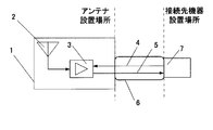
- FIG. 10 shows an example of a conventional antenna device.
- An antenna device 1 installed at an antenna installation location (for example, a vehicle roof) includes an antenna element 2 and an antenna reception amplifier 3 connected thereto.
- a power line 4 to the antenna reception amplifier 3 and a coaxial line 5 that transmits the output of the antenna reception amplifier 3 are connected to a demodulated received signal through a wiring path 6 provided in the vehicle body for display and audio signal extraction. It is connected to the device 7.
- the connection destination device 7 installed in the connection destination device installation location is an AM / FM radio receiver or the like. .
- FIG. 11A shows an example in which the camera 8 is mounted inside the antenna device 1 of FIG. 10, and the power line 9 and the signal line 10 are connected to the camera 8.
- the power supply line 9 and the signal line 10 are connected to a monitor 11 as a connection destination device of the camera 8 via the wiring path 6 as in FIG.
- FIG. 11B is an example in which the camera 8 is mounted in the vicinity of the antenna device 1 of FIG. 10.
- the power supply line 9 and the signal line 10 are connected to the camera 8 via the wiring path 6. It is connected to a monitor 11 as a connection destination device.
- Patent Document 1 shows a configuration in which a camera is provided in the case of an antenna device, but Patent Document 1 does not give consideration to reducing the number of wires.
- a signal leaking from a camera signal line or the like wired in the vicinity of the antenna device may interfere with a device such as a radio receiver that receives and uses a weak signal such as an antenna reception signal.
- Some camera signal transmission means perform signal transmission wirelessly.
- an antenna that can appropriately transmit a signal from the camera is required.
- the vehicle uses a lot of metal parts, placing the antenna in an inconspicuous place giving priority to aesthetics hides the antenna behind the metal parts, making it difficult to ensure the stability of communication.
- the wireless transmission path may change due to external factors such as weather conditions, reflection of the surrounding environment, or loading of luggage or personnel.
- the camera image is transmitted to a monitor or the like wirelessly such as Wi-Fi, the transmission time takes several ms, so the image displayed on the monitor or the like is not a real-time image.
- the camera signal when transmitted wirelessly, if there is a device that uses a signal of the same frequency at the destination or route of the vehicle, or if another wireless device is used in the passenger compartment, Or, on the contrary, may interfere with the equipment. In the case of an automobile corresponding to a wide variety of usage forms, it is difficult to completely avoid these causes of interference.
- the present invention has been made in view of such a situation, and its purpose is to suppress an increase in the number of wires and suppress noise generation when a camera is placed in or near the antenna device.
- Another object of the present invention is to provide a vehicle-mounted antenna device with a camera that can improve wiring workability in a required wiring route.
- the antenna in the present invention refers to a part necessary for radio wave reception in which only an antenna element or a combination of a matching circuit and a reception amplifier is used.
- the camera-equipped antenna device is not limited to the case where the camera is mounted inside the case of the antenna device. Even if the camera is installed near the case of the antenna device and the signal line or the power line penetrates the housing of the antenna device or is connected to the antenna device by a connector, it is called an antenna device with a camera.
- An aspect of the present invention is a vehicle-mounted antenna device with a camera.
- the vehicle-mounted antenna device with a camera includes a signal superimposing unit that frequency-converts an output signal of the camera and superimposing the received signal of the antenna, and a coaxial line that transmits the superimposed signal output from the signal superimposing unit.
- a power supply superimposing unit that superimposes a camera power supply on the coaxial line is further provided, and power is supplied to the camera via the coaxial line.
- a power supply superimposing unit that superimposes an antenna power supply on the coaxial line is further provided, and the power output from the power superimposing unit is supplied to the antenna via the coaxial line.
- the antenna, the camera, and the signal superimposing unit may be provided outside the passenger compartment.
- the antenna and the camera may be provided outside the passenger compartment, and the signal superimposing unit may be provided in the passenger compartment.
- the antenna, the camera, and the signal superimposing unit may be provided in a vehicle interior.
- the output signal frequency-converted by the signal superimposing unit is demultiplexed from the coaxial line, and the output signal frequency-converted by the signal superimposing unit is frequency-converted again, and the camera It is preferable to further include a frequency conversion unit that restores the output signal.
- the frequency used in the signal superimposing unit and the frequency used in the frequency converting unit may be the same frequency.
- the antenna is housed in a case disposed outside the passenger compartment, the camera is attached to the case or disposed near the case, and the height of the case is 70 mm or less.
- the output signal of the camera is frequency-converted and superimposed on the coaxial line for transmitting the antenna reception signal, thereby transmitting a wire while ensuring a stable wired connection.
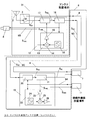
- Embodiment 1 which shows the circuit structure of the vehicle-mounted antenna apparatus with a camera concerning this invention, Comprising: The block diagram which shows the structural example which arrange
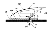
- FIG. 3 is a side cross-sectional view showing a schematic structure in the case of a configuration example in which a camera is arranged in an antenna unit installed outside a vehicle compartment in the first embodiment.
- FIG. 3 is a side cross-sectional view showing a schematic structure in the case of a configuration example in which a camera is arranged in an antenna unit installed outside a vehicle compartment in the first embodiment.
- FIG. 3 is a side cross-sectional view showing a schematic structure in the case of a configuration example in which a camera is disposed in the vicinity of the outside of an antenna unit installed outside the passenger compartment in the first embodiment.
- the camera output signal S 5B after the frequency conversion, and the restored camera video signal S 10D is compared.
- Graph shown shown.
- the fourth embodiment in order to superimpose the camera video signal S 10A in coaxial line 5C for transmitting the received signals obtained by amplifying the signal received by the antenna element 2 by an antenna for receiving amplifier 3, up-converts the camera video signal S 10A graph showing camera output signal S 5B, in contrast to the power (dBm) of the original camera image signal S 10A and the restored camera video signal S 10D in the 2.4GHz band.
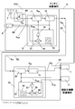
- FIG. 11 is a block diagram showing another antenna device in which a camera is added to the conventional configuration of FIG. 10.
- Embodiment 1-1 1A and 1B are block diagrams showing a circuit configuration of a vehicle-mounted antenna device with a camera according to a first embodiment of the present invention, and FIGS. 2A and 2B show a case where the antenna unit of the first embodiment is installed outside a vehicle compartment. It is a sectional side view showing a schematic structure.
- a vehicle-mounted antenna device 30 with a camera includes, for example, an antenna unit 31 mounted on a vehicle body roof or the like, a signal separation / power supply in the vicinity of a unit 7 and a monitor 11 that are connection destinations on a wiring path 6. And a superimposing circuit 19.
- FIGS. 1A and 2A show a configuration example in which the camera 8 is arranged in the antenna unit 31.
- the camera 8 is attached to a case 32 of the antenna unit 31.
- FIG. 1B and 2B show a configuration example in which the camera 8 is arranged in the vicinity of the outside of the antenna unit 31, that is, in the vicinity of the case 32. Except for the arrangement position of the camera 8, the vehicle-mounted vehicle shown in FIGS. 1A and 2A The configuration is the same as that of the antenna device, and the same operation is performed.
- the antenna unit 31 installed at the antenna installation location includes an antenna element 2 (for example, for AM / FM radio broadcasting), an antenna reception amplifier 3 connected to the antenna element 2, a camera 8 for imaging the periphery of the vehicle body, and signal superposition.
- a power supply separation circuit (signal superimposing unit / power supply separation unit) 12 that is housed in an internal space of a case 32 that includes a base 32A and a radio wave transmissive cover 32B that covers the base 32A as shown in FIG. 2A It is. However, a portion of the cover 32B corresponding to the lens of the camera 8 is formed with a through hole or a transparent member so that the outside can be seen through.
- the signal superimposing / power source separation circuit 12 includes a frequency conversion transmission circuit 13, a multiplexing circuit (multiplexing unit) 17, and a power source separation circuit (power source separation unit) 18.
- the frequency conversion transmission circuit 13 includes a transmission-side mixer 14, a transmission-side oscillator 15, and a transmission-side amplifier 16.
- the antenna reception amplifier 3 and the signal superposition / power source separation circuit 12 are provided on a fixed circuit board 34 on a base 32A shown in FIG. 2A.
- the case 32 in FIG. 2A has, for example, a shark fin shape, and when installed on the vehicle body roof, the height H from the bottom surface of the base 32A is preferably 70 mm or less.
- the signal separation / power supply superimposition circuit (signal separation unit / power supply superposition unit) 19 includes a power supply superposition circuit 20, a demultiplexing circuit (demultiplexing unit) 21, and a frequency conversion receiving circuit (frequency conversion unit) 22.
- the frequency conversion reception circuit 22 includes a reception side amplifier 23, a reception side oscillator 24, a reception side mixer 25, and a signal amplifier 26.
- the signal separation / power supply superimposing circuit 19 is connected to a unit 7 such as a radio receiver and a camera monitor 11 arranged on the vehicle interior side as a connection destination device installation location.
- the signal superposition / power source separation circuit 12 and the signal separation / power source superposition circuit 19 of the antenna unit 31 are connected by a single coaxial line 5C passing through a wiring hole 50 (included in the wiring path 6) formed in the vehicle body 35. Has been. Also, DC power is supplied from the unit 7 in the vehicle compartment to the antenna reception amplifier 3 via the power line 4 passing through the wiring hole 50. A total of two power supply lines 4 and coaxial lines 5C pass through the wiring holes 50. Further, DC power is supplied to the power superimposing circuit 20 and the frequency conversion receiving circuit 22 via the power line 9A from the monitor 11 to the camera.
- direct current power is supplied to the antenna reception amplifier 3 from the unit 7 in the passenger compartment via the power line 4 passing through the wiring path 6.
- a camera DC power supply is supplied to the camera power supply line 9A from the camera monitor 11, and the camera DC power supply is superimposed on the coaxial line 5C by the power supply superimposing circuit 20 and passes through the coaxial line 5C.
- the power supply separation circuit 18 of the antenna unit 31 is reached. Only the DC power supply component is separated by the power supply separation circuit 18 and output to the power supply line 9B, and the DC power supply is supplied to the frequency conversion transmission circuit 13 and the camera 8 to operate them. Note that the camera DC power supply is superimposed such that, for example, the core wire of the coaxial line 5C is on the + side and the outer conductor is on the-side.
- the reception signal of the antenna element 2 is amplified by the antenna reception amplifier 3, and the antenna reception signal S 5 A , which is the output of the antenna reception amplifier 3, is applied to the multiplexing circuit 17 in the signal superposition / power supply separation circuit 12.
- the camera video signal S 10A as an output signal output from the camera 8 is input to the transmission-side mixer 14 inside the frequency conversion transmission circuit 13 and mixed with the signal of the transmission-side oscillator 15 so that the frequency is increased.
- the signal is converted, amplified by the transmission side amplifier 16, and input to the multiplexing circuit 17 as the signal S10B after frequency conversion.
- the antenna reception signal S5A and the signal S10B are multiplexed, superimposed on the same signal line, and output as the signal S5B .
- Signal S 5B is a top coaxial line 5C propagates as a signal S 5C via the power separating circuit 18, the signal separation and power superimposition circuit 19 within via to next signal S 5D power superposition circuit 20, diplexer circuit The signal is demultiplexed at 21 to become a signal S10C .
- the signal S 10C is input to the receiving side amplifier 23 in the frequency conversion receiving circuit 22 and amplified, and is mixed with the signal of the receiving side oscillator 24 by the receiving side mixer 25 to be the original frequency (camera video signal S 10A and The signal is restored to substantially the same frequency), and is amplified again by the signal amplifier 26, whereby the restored camera video signal S10D is obtained.
- the camera video signal S 10D substantially the same as the camera video signal S 10A can be restored, and the camera video signal S 10D is input to the monitor 11.
- both the transmission-side oscillator 15 and the reception-side oscillator 24 built in the frequency conversion transmission circuit 13 and the frequency conversion reception circuit 22 have the same frequency so that they can be extracted as video signals having the same frequency before and after conversion. I can do it.
- the amplitude of the video signal is adjusted by the gains of the individual amplifiers 16, 23, and 26, and the attenuation amounts of the multiplexing circuit 17, power supply separation circuit 18, power supply superimposing circuit 20, and branching circuit 21.
- the antenna reception signal S 5A is transmitted in the order of the signal S 5B , the signal S 5C , the signal S 5D , and the antenna reception signal S 5E through the above-described processing, and reaches the unit 7 such as a radio receiver that is the original connection destination. To do.
- the antenna unit 31 is connected to the unit 7 and the monitor 11 to which the antenna unit 31 is connected. Is possible. Therefore, the transmission of the camera video signal can be performed with a stable wired connection, and the transmission and reception of interference via the space when using the wireless connection can be avoided. In other words, it is possible to avoid a change in the wireless environment that may occur depending on the use situation of the automobile (interference transfer or change in transmission path).
- FIG. 3 is a block diagram showing a circuit configuration of Embodiment 2 of the vehicle-mounted antenna device with a camera according to the present invention.
- the vehicle-mounted antenna device 30 ⁇ / b> A with the camera includes an antenna unit 31 ⁇ / b> A installed at the antenna installation location, a signal superposition / power source separation circuit 12, and a signal separation / power source superposition circuit 19 on the wiring path 6.
- the antenna unit 31A includes an antenna element 2 (for example, for AM / FM radio broadcast reception), an antenna reception amplifier 3 connected to the antenna element 2, and a camera 8 for imaging the surroundings of the vehicle body.
- the circuit 12 does not have.
- the signal superposition / power supply separation circuit 12 is arranged in the vicinity of the antenna unit 31A on the wiring path 6, and the signal separation / power supply superposition circuit 19 is arranged in the vicinity of the unit 7 and the monitor 11 to be connected.
- Other configurations are the same as those of the first embodiment.
- the external dimensions of the antenna unit 31A can be made smaller than that of the configuration of the first embodiment, and can be made comparable to the external dimensions of the conventional example of FIG. 11A.
- the number of components inside the case is smaller than the configuration of the first embodiment, when the antenna unit 31A is installed outside the passenger compartment, the height from the bottom surface of the case is set to 70 mm or less. Will also be easier.
- the same effect can be obtained by arranging the camera 8 near the outside of the antenna unit 31A as shown in FIG. 2B described in the first embodiment.
- FIG. 4 is a block diagram showing a circuit configuration of Embodiment 3 of the vehicle-mounted antenna device with a camera according to the present invention.
- the vehicle-mounted antenna device 30B with the camera includes an antenna unit 31B and a signal separation circuit (signal separation unit) 19A in the vicinity of the connection destination on the wiring path 6 and the monitor 11.
- DC power is supplied to the antenna receiving amplifier 3 from the unit 7 such as a radio receiver in the vehicle interior using the power line 4 passing through the wiring path 6 of the vehicle body, and to a dedicated camera passing through the wiring path 6.
- DC power is supplied to the camera 8 from the monitor 11 in the passenger compartment using the power line 9A.
- the signal superposition circuit 12A does not require the power supply separation circuit 18 in the first embodiment, and the signal separation circuit 19A does not require the power supply superposition circuit 20.
- the circuit configuration of the antenna unit 31B and the signal separation circuit 19A can be simplified, and the external shape and installation space of the antenna unit 31B and the signal separation circuit 19A can be reduced to facilitate installation.
- Other configurations are the same as those of the first embodiment.
- the same effect can be obtained by arranging the camera 8 in the vicinity of the outside of the antenna unit 31B as shown in FIGS. 1B and 2B described in the first embodiment.
- FIG. 5 is a block diagram showing a circuit configuration of Embodiment 4 of the vehicle-mounted antenna device with a camera according to the present invention.
- the on-vehicle antenna device 30C with a camera includes an antenna unit 31C, a signal superimposing circuit 12A on the wiring path 6, and a signal separating circuit 19A.
- the signal superimposing circuit 12A is arranged in the vicinity of the antenna unit 31C on the wiring path 6.
- Other configurations are the same as those of the third embodiment.
- the external dimensions of the antenna unit 31C can be reduced compared to the configuration of the third embodiment. Further, since the number of components inside the case is small, it is easy to set the height from the bottom surface of the case to 70 mm or less when the antenna unit 31 is installed outside the passenger compartment.
- the same effect can be obtained by arranging the camera 8 in the vicinity of the outside of the vehicle compartment antenna unit 31C as shown in FIG. 2B described in the first embodiment.
- FIG. 5 Embodiment 4
- the antenna element 2 and the antenna receiving amplifier 3 are configured as AM / FM antennas
- the camera 8 is combined.
- This is a frequency spectrum when the frequency of 10A is converted and superimposed on the antenna reception signal S5A, and the superimposed signal is demodulated again into the original camera video signal S10D .
- the 3.5 MHz band in the case of the NTSC signal
- FIG. 7 show the spectrum of the 2.4 GHz band (frequency band up-converted for superposition) that does not interfere with AM / FM radio broadcasting.
- the camera video signal S 10A from the camera 8 moves by up-converting to another frequency (2.4 GHz in the experiment) in the signal S 5B , disappears from the 3.5 MHz band, and is input to the monitor 11.
- the demodulated camera video signal S10D is restored to the original frequency again. Since the signal S signal components from 3.5MHz band in 5B coaxial line 5C disappears, for example, it does not interfere with AM radio reception signal (500kHz ⁇ 2MHz).
- the 2.4 GHz band signal is not output in the camera video signal S 10A from the camera 8, but by up-conversion, the signal component appears in the 2.4 GHz band in the signal S 5B and is demodulated.
- the camera video signal S 10D which is restored by frequency conversion to the original frequency band later, the signal component disappears from the 2.4 GHz band.
- the camera video signal S10A is frequency-converted to the 2.4 GHz band. Since it can be superimposed on the coaxial line 5C and transmitted (signal S 5B ) and restored to the original signal at the transmission destination (reconstructed camera video signal S 10D ), avoid interference with radio broadcast reception signals. It can be seen that video signals can be transmitted simultaneously on the same coaxial line. Further, since the signal S5B does not have a signal spectrum of the radio broadcast band, it is possible to avoid interference with radio broadcast reception due to signal leakage.
- FIG. 8 is a block diagram showing a circuit configuration of Embodiment 5 of the vehicle-mounted antenna device with a camera according to the present invention.
- the on-vehicle antenna device 30 ⁇ / b> D with a camera includes an antenna unit 31 ⁇ / b> D, a signal separation / power supply superimposing circuit 19 in the vicinity of the unit 7 and the monitor 11 that are connection destinations on the wiring path 6.
- the DC power supply for the antenna amplifier 3 and the camera 8 is shared, and the power supply superposition circuit 20 in the signal separation / power superposition circuit 19 and the unit 7 such as a receiver in the vehicle interior via the power line 4A and A DC power is supplied to the frequency conversion receiving circuit 22.
- the DC power is superimposed on the coaxial line 5C by the antenna amplifier 3 and the power supply superimposing circuit 20 for the camera, and reaches the power separation circuit 18 of the antenna unit 31D via the coaxial line 5C. Only the DC power supply component is separated by the power supply separation circuit 18 and output to the power supply lines 4B and 9B. The DC power is supplied to the antenna amplifier 3 and the camera 8, and these can be operated. Other configurations are the same as those in the first embodiment.
- the wiring passing through the wiring path 6 can be only one of the coaxial lines 5C, so that the wiring work can be further simplified. is there.
- the same effect can be obtained by arranging the camera 8 near the outside of the antenna unit 31D as shown in FIG. 2B described in the first embodiment.
- FIG. 9 is a block diagram showing a circuit configuration of Embodiment 6 of the vehicle-mounted antenna device with a camera according to the present invention.
- the vehicle-mounted antenna device 30 ⁇ / b> E with the camera includes an antenna unit 31 ⁇ / b> E, a signal superposition / power source separation circuit 12, and a signal separation / power source superposition circuit 19 on the wiring path 6.
- the signal superimposing / power source separation circuit 12 is disposed in the vicinity of the antenna unit 31E on the wiring path 6.
- Other configurations are the same as those of the fifth embodiment.
- the external dimensions of the antenna unit 31E can be reduced compared to the configuration of the fifth embodiment.
- the number of components inside the case is small, when the antenna unit 31E is installed outside the passenger compartment, it is easy to set the height from the bottom surface of the case to 70 mm or less.
- the same effect can be obtained by arranging the camera 8 near the outside of the antenna unit 31E as shown in FIG. 2B described in the first embodiment.
- the antenna 2, the camera 8, and the circuit configuration including the signal superimposing / power source separating circuit 12 may be provided in the vehicle interior.
- a circuit that multiplexes or demultiplexes two types of signals such as a multiplexing circuit 17 built in the signal superposition / power supply separation circuit 12 and a demultiplexing circuit 21 built in the signal separation / power supply superposition circuit 19.
- a diplexer combining a low-pass filter, a high-pass filter, a band-pass filter, a band emission filter, and the like can be used.
- the transmission-side amplifier 16, the reception-side amplifier 23, and the signal amplifier 26 can be partially or completely omitted if there is no problem in signal transmission and restoration, and a part or all of the transmission-side mixer 14 or the active-mixer can be omitted.
- a circuit configuration integrated with the receiving-side mixer 25 may be used.
- the antenna is not limited to radio broadcasting, and even with a receiving antenna for navigation satellite systems (GPS / GNSS), telephones, satellite radio, television broadcasting, etc., the frequency for converting the output signal of the camera can be set appropriately. It can be superimposed on a coaxial line.
- GPS navigation satellite systems
- GNSS navigation satellite systems
- telephones satellite radio
- television broadcasting etc.
- the frequency for converting the output signal of the camera can be set appropriately. It can be superimposed on a coaxial line.
- the number of wirings can be reduced by applying the present invention.
- the output signal from the camera has various formats, but even an analog composite signal such as NTSC or a serial digital signal (LVDS or the like) can be transmitted by being superimposed on the antenna reception signal with the same configuration.
- an analog composite signal such as NTSC or a serial digital signal (LVDS or the like) can be transmitted by being superimposed on the antenna reception signal with the same configuration.
Landscapes
- Engineering & Computer Science (AREA)
- Signal Processing (AREA)
- Computer Networks & Wireless Communication (AREA)
- Multimedia (AREA)
- Mechanical Engineering (AREA)
- Fittings On The Vehicle Exterior For Carrying Loads, And Devices For Holding Or Mounting Articles (AREA)
- Studio Devices (AREA)
- Structure Of Receivers (AREA)
Abstract
アンテナに加えてカメラを有する場合に、配線本数の増加を抑制して、車室内の配線作業性を容易にし、かつ作業性を良好にする。 アンテナ素子2及びカメラ8が車室外に設置されたカメラ付き車載アンテナ装置において、カメラ8の出力信号を周波数変換し、同軸線5Cにアンテナの受信信号と共に重畳させて伝送するとともに、同軸線5Cに直流電圧を重畳し、同軸線5Cを経由してカメラ8に電源を供給する。
Description
本発明は、車両に設置するのに適したカメラ付き車載アンテナ装置に関する。
近年、自動車にカメラを搭載する例が増えてきている。例えば、自動車の周囲の映像を取り込むためのカメラを、車両に設置したアンテナ装置内又は近傍に搭載する場合、既存のアンテナからの出力同軸線(同軸ケーブル)及び電源線と同様に、カメラ及び付属機器の電源線及び信号線を車両のアンテナ配線経路を通して所定の接続先となる機器まで配線する必要がある。
この時、必要な信号線及び電源線が当初から車両の設計に見込まれていない場合には、配線経路の確保が難しくなる。仮に、配線経路を確保できたとしても、自動車の配線に関する技量が求められる可能性がある。
こうしたことが、車両に設置されたアンテナ装置内又は近傍にカメラを搭載したり、カメラを搭載したアンテナ装置と取り替えたりすることに対する障壁の一つとなっている。
図10は従来のアンテナ装置の例であって、アンテナ設置場所(例えば車両ルーフ)に設置されたアンテナ装置1は、アンテナ素子2及びこれに接続されたアンテナ用受信増幅器3を内蔵している。アンテナ用受信増幅器3への電源線4及びアンテナ用受信増幅器3の出力を伝送する同軸線5は、車体に設けられた配線経路6を通して、受信信号を復調し表示や音声信号取り出しを行う接続先機器7に接続されている。例えば、アンテナ素子2及びアンテナ用受信増幅器3がAM/FMラジオ放送用であれば、接続先機器設置場所(例えば車室内)に設置された接続先機器7はAM/FMラジオ受信機等である。
図11Aは図10のアンテナ装置1の内部にカメラ8を搭載した例であって、カメラ8に電源線9及び信号線10が接続されている。この例では、電源線9と信号線10は、図10と同様に配線経路6を経由して、カメラ8の接続先機器としてのモニタ11に接続されている。
図11Bは図10のアンテナ装置1の近傍にカメラ8を搭載した例であって、図10や図11Aと同様に、電源線9及び信号線10は配線経路6を経由して、カメラ8の接続先機器としてのモニタ11に接続されている。
特許文献1はアンテナ装置のケースにカメラを設けた構成を示すが、特許文献1には配線本数の低減についての配慮はみられない。
上記図11A及び図11Bのアンテナ装置では、カメラを配置したことで、信号線や電源線の本数が増え、配線経路の確保が困難になる。また、アンテナ装置の近傍に配線されたカメラの信号線等から漏洩する信号が、アンテナ受信信号等の微弱信号を受信して利用するラジオ受信機等の機器を妨害する場合がある。
カメラ信号の信号伝送手段として、無線で信号伝送を行うものがある。この場合に、カメラからの信号を適切に伝送出来る様なアンテナが必要となる。この時、車両は金属部品を多用しているため、美観を優先してアンテナを目立たない場所に配置すると、それらの金属部品の陰にアンテナが隠れてしまい、通信の安定性確保が難しい。また、無線信号伝送に対し好適な設置とした場合であっても、気象条件や周辺環境の反射或いは荷物や人員の積載等の外的要因により、無線伝送路が変化してしまう可能性がある。更に、カメラの画像をWi-Fi等の無線でモニタ等に伝送すると伝送時間に数msかかるため、モニタ等に映し出される画像がリアルタイムな画像では無くなる。
更に、カメラ信号を無線で伝送すると、車両の移動先や移動経路に同様の周波数の信号を使用している機器が存在したり車室内で他の無線機器を使用した場合には、その機器からの妨害を受けたり、反対に、その機器へ妨害を与えたりする可能性がある。多種多様な利用形態に対応する自動車の場合にはこれらの妨害授受の要因を完全に回避することは困難である。
本発明はこうした状況を認識してなされたものであり、その目的は、アンテナ装置内又はアンテナ装置近傍にカメラを配置する場合に、配線本数の増加を抑制して、ノイズ発生を抑制し、また、求められる配線経路における配線作業性を良好にすることが可能なカメラ付き車載アンテナ装置を提供することにある。
尚、本発明におけるアンテナとは、アンテナ素子のみ、又はアンテナ素子に整合回路や受信アンプ等を組み合わせた電波受信に必要となる部位を示す。
また、本発明におけるカメラ付きアンテナ装置とは、アンテナ装置のケース内部にカメラを搭載した場合に限られない。カメラがアンテナ装置のケース近傍に設置され、信号線又は電源線がアンテナ装置の筐体を貫通またはアンテナ装置にコネクタ接続される構造であってもカメラ付きアンテナ装置と呼称する。
本発明のある態様はカメラ付き車載アンテナ装置である。このカメラ付き車載アンテナ装置は、カメラの出力信号を周波数変換し、アンテナの受信信号と重畳させる信号重畳部と、該信号重畳部から出力された重畳信号を伝送する同軸線と、を備えることを特徴とする。
前記態様において、前記同軸線にカメラ用電源を重畳する電源重畳部と、を更に備え、前記同軸線を経由して前記カメラに電源を供給するとよい。
前記態様において、前記同軸線にアンテナ用電源を重畳する電源重畳部と、を更に備え、前記同軸線を経由して、前記アンテナに前記電源重畳部から出力された電源を供給するとよい。
前記態様において、前記アンテナと、前記カメラと、前記信号重畳部とが車室外に設けられているとよい。
前記態様において、前記アンテナ及び前記カメラが車室外に設けられ、前記信号重畳部が車室内に設けられているとよい。
前記態様において、前記アンテナと、前記カメラと、前記信号重畳部とが車室内に設けられているとよい。
前記態様において、前記信号重畳部で周波数変換された出力信号を、前記同軸線から分波する分波部と、前記信号重畳部で周波数変換された前記出力信号を再度周波数変換して前記カメラの出力信号を復元する周波数変換部と、を更に備えるとよい。
前記態様において、前記信号重畳部で用いる周波数と、前記周波数変換部で用いる周波数とが、同じ周波数であるとよい。
前記態様において、前記アンテナが車室外に配置されたケース内に収容され、前記カメラは前記ケースに取り付けられるか前記ケース近傍に配置されており、前記ケースの高さが70mm以下であるとよい。
なお、以上の構成要素の任意の組合せ、本発明の表現を方法やシステム等の間で変換したものもまた、本発明の態様として有効である。
本発明に係るカメラ付き車載アンテナ装置によれば、カメラの出力信号を周波数変換し、アンテナの受信信号を伝送する同軸線上に重畳させて伝送することで、安定した有線接続を確保しつつ配線の本数を減らし、車両の配線作業を容易にするとともに、作業工数の低減、ケーブル等の配線材料の低減、ノイズ発生及び放射の抑制(画像伝送周波数の変更に伴うノイズ周波数の変更による受信妨害軽減)を図ることが可能である。
以下、図面を参照しながら本発明の好適な実施の形態を詳述する。なお、各図面に示される同一または同等の構成要素、部材、処理等には同一の符号を付し、適宜重複した説明は省略する。また、実施の形態は発明を限定するものではなく例示であり、実施の形態に記述されるすべての特徴やその組み合わせは必ずしも発明の本質的なものであるとは限らない。
実施の形態1-1
図1A及び図1Bは、本発明に係るカメラ付き車載アンテナ装置の実施の形態1の回路構成を示すブロック図、図2A及び図2Bは実施の形態1のアンテナユニットを車室外に設置した場合の概略構造を示す側断面図である。これらの図に示すように、カメラ付き車載アンテナ装置30は、例えば車体ルーフ等に搭載されるアンテナユニット31と、配線経路6上の接続先となるユニット7及びモニタ11の近傍に信号分離・電源重畳回路19とを備える。
図1A及び図1Bは、本発明に係るカメラ付き車載アンテナ装置の実施の形態1の回路構成を示すブロック図、図2A及び図2Bは実施の形態1のアンテナユニットを車室外に設置した場合の概略構造を示す側断面図である。これらの図に示すように、カメラ付き車載アンテナ装置30は、例えば車体ルーフ等に搭載されるアンテナユニット31と、配線経路6上の接続先となるユニット7及びモニタ11の近傍に信号分離・電源重畳回路19とを備える。
なお、図1A及び図2Aは、アンテナユニット31内にカメラ8を配置する構成例を示し、例えばカメラ8はアンテナユニット31のケース32に取り付けられている。図1B及び図2Bは、アンテナユニット31の外側近傍、つまりケース32の近傍にカメラ8を配置する構成例を示しており、カメラ8の配置位置以外は、図1A及び図2Aに示すカメラ付き車載アンテナ装置と同様の構成であり、同様に動作する。
以下、便宜上、図1A及び図2Aに示すカメラ付き車載アンテナ装置30について説明する。
アンテナ設置場所に設置されたアンテナユニット31は、アンテナ素子2(例えば、AM/FMラジオ放送用)と、これに接続されたアンテナ用受信増幅器3と、車体周囲を撮像するカメラ8と、信号重畳・電源分離回路(信号重畳部/電源分離部)12を有し、図2Aのように、これらをベース32Aとこれを覆う電波透過性のカバー32Bとからなるケース32の内部空間に収納したものである。但し、カバー32Bのカメラ8のレンズに対応する部分は、外部が透視可能なように透孔が形成されるか、透明部材が配置される。信号重畳・電源分離回路12は、周波数変換送信回路13と、合波回路(合波部)17と、電源分離回路(電源分離部)18とを有する。周波数変換送信回路13は、送信側混合器14と、送信側発振器15と、送信側増幅器16とを有する。アンテナ用受信増幅器3及び信号重畳・電源分離回路12は図2Aに示すベース32A上に固定の回路基板34に設けられている。図2Aのケース32は例えばシャークフィン形状であり、車体ルーフ上に設置する場合には、ベース32Aの底面からの高さHは、70mm以下であることが好ましい。
信号分離・電源重畳回路(信号分離部/電源重畳部)19は、電源重畳回路20と、分波回路(分波部)21と、周波数変換受信回路(周波数変換部)22とを有する。周波数変換受信回路22は、受信側増幅器23と、受信側発振器24と、受信側混合器25と、信号増幅器26とを有する。信号分離・電源重畳回路19は、接続先機器設置場所としての車室内側に配置されたラジオ受信機等のユニット7及びカメラのモニタ11にそれぞれ接続されている。アンテナユニット31の信号重畳・電源分離回路12と、信号分離・電源重畳回路19とは、車体35に作られた配線孔50(配線経路6に含まれる)を通る1本の同軸線5Cで接続されている。また、配線孔50を通る電源線4を経由して車室内のユニット7からアンテナ用受信増幅器3に直流電源が供給される。配線孔50を通るのは、電源線4と同軸線5Cの合計2本である。また、モニタ11からカメラへの電源線9Aを経由して電源重畳回路20及び周波数変換受信回路22に直流電源が供給される。
次に実施の形態1の動作を説明する。図1Aにおいて、アンテナ用受信増幅器3には、配線経路6を通る電源線4を経由して車室内のユニット7から直流電源が供給される。また、カメラへの電源線9Aにはカメラのモニタ11からカメラ用直流電源が供給され、このカメラ用直流電源は電源重畳回路20で同軸線5C上に電源重畳され、同軸線5Cを経由してアンテナユニット31の電源分離回路18に到達する。電源分離回路18で直流電源成分のみ分離されて電源線9Bに出力され、周波数変換送信回路13及びカメラ8に直流電源が供給され、これらを動作させることが出来る。なお、カメラ用直流電源は、例えば、同軸線5Cの芯線が+側、外被導体が-側となるように重畳される。
アンテナ素子2の受信信号はアンテナ用受信増幅器3で増幅され、アンテナ用受信増幅器3の出力であるアンテナ受信信号S5Aは、信号重畳・電源分離回路12内の合波回路17に加えられる。一方、カメラ8から出力された出力信号としてのカメラ映像信号S10Aは、周波数変換送信回路13の内部の送信側混合器14に入力され、送信側発振器15の信号と混合されることで周波数が変換され、送信側増幅器16で増幅されて周波数変換後の信号S10Bとして合波回路17に入力される。合波回路17ではアンテナ受信信号S5Aと信号S10Bを合波して、同一信号線上に重畳して信号S5Bとして出力する。信号S5Bは、電源分離回路18を経由して信号S5Cとして同軸線5C上を伝搬し、信号分離・電源重畳回路19内の電源重畳回路20を経由して信号S5Dとなり、分波回路21で分波されて信号S10Cとなる。信号S10Cは周波数変換受信回路22の内部の受信側増幅器23に入力されて増幅され、受信側混合器25にて受信側発振器24の信号と混合されて元の周波数(カメラ映像信号S10Aと実質的に同じ周波数)に復元され、信号増幅器26で再び増幅されることで復元されたカメラ映像信号S10Dとなる。これらの処理により、カメラ映像信号S10Aと実質的に同じカメラ映像信号S10Dを復元することができ、カメラ映像信号S10Dはモニタ11に入力される。
なお、周波数変換送信回路13と周波数変換受信回路22にそれぞれ内蔵される送信側発振器15及び受信側発振器24の両発振器は同じ周波数とすることで、変換前後で同じ周波数の映像信号として取り出すことが出来る。映像信号の振幅は、個別の増幅器16,23,26の利得や、合波回路17、電源分離回路18、電源重畳回路20、及び分波回路21の減衰量で調整される。
アンテナ受信信号S5Aは、前述の処理を経ながら信号S5B、信号S5C、信号S5D、アンテナ受信信号S5Eの順に伝送され、本来の接続先であるラジオ受信機等のユニット7に到達する。
本実施の形態によれば、下記の効果を奏することができる。
(1) カメラ8のカメラ映像信号S10Aの周波数を変換させることにより、ラジオ等のアンテナ受信信号S5Aとの相互干渉を避けることが出来、かつ信号や電源電圧を同一同軸線5C上に重畳して伝送することが出来る。これにより、カメラ8の信号線及び電源線の配線を別途設ける必要がなくカメラ8の設置が可能となり、スペースの制限された状況においても配線が可能となる。また、ノイズ放射の可能性のあるケーブル等の配線を最小限に抑えられる。また、カメラ8の信号線を単純に設けるとそこからの信号漏洩によりラジオ受信等を妨害しやすいのに対し、カメラ映像信号S10Aの周波数を移動しているので漏洩による妨害を回避できる。
(2) 車体35に作られた配線孔50を含む配線経路6がカメラの搭載を前提としない寸法、形状であっても、アンテナユニット31と接続先となるユニット7及びモニタ11との有線接続が可能となる。従って、カメラ映像信号の伝送を安定した有線接続で行うことができ、無線接続使用時の空間経由での妨害の授受を回避できる。つまり、自動車の使用状況に応じて起こり得る無線環境の変化(妨害の授受や伝送路の変化)を回避することが出来る。
(3) ケース32のベース底面からの高さを、70mm以下に設定することで、車体ルーフ上に好適に設置可能である。
(4) 図1B及び図2Bに示す、カメラ8がアンテナユニット31の外側近傍(つまりケース32の近傍)に設置され、信号線又は電源線がアンテナユニットを通過する構成例の場合にも同様の回路動作を行い、上記(1)-(3)と同じ効果が得られる。
実施の形態2
図3は本発明に係るカメラ付き車載アンテナ装置の実施の形態2の回路構成を示すブロック図である。図3に示すように、カメラ付き車載アンテナ装置30Aは、アンテナ設置場所に設置されるアンテナユニット31Aと、配線経路6上に信号重畳・電源分離回路12と、信号分離・電源重畳回路19とを備える。アンテナユニット31Aは、アンテナ素子2(例えば、AM/FMラジオ放送受信用)と、これに接続されたアンテナ用受信増幅器3と、車体周囲を撮像するカメラ8とを有するが、信号重畳・電源分離回路12は有しない。この場合、信号重畳・電源分離回路12は、配線経路6上のアンテナユニット31A近傍に配置され、信号分離・電源重畳回路19は接続先となるユニット7及びモニタ11の近傍に配置される。その他の構成は前述の実施の形態1と同様である。
図3は本発明に係るカメラ付き車載アンテナ装置の実施の形態2の回路構成を示すブロック図である。図3に示すように、カメラ付き車載アンテナ装置30Aは、アンテナ設置場所に設置されるアンテナユニット31Aと、配線経路6上に信号重畳・電源分離回路12と、信号分離・電源重畳回路19とを備える。アンテナユニット31Aは、アンテナ素子2(例えば、AM/FMラジオ放送受信用)と、これに接続されたアンテナ用受信増幅器3と、車体周囲を撮像するカメラ8とを有するが、信号重畳・電源分離回路12は有しない。この場合、信号重畳・電源分離回路12は、配線経路6上のアンテナユニット31A近傍に配置され、信号分離・電源重畳回路19は接続先となるユニット7及びモニタ11の近傍に配置される。その他の構成は前述の実施の形態1と同様である。
この実施の形態2によれば、実施の形態1の構成よりも、アンテナユニット31Aの外形寸法を小形化でき、図11Aの従来例の外形寸法と同程度にすることが可能である。また、実施の形態1の構成よりも、ケース内部の構成部品が少なくて済むため、アンテナユニット31Aを車室外に設置する場合においてはケースのベース底面からの高さを、70mm以下に設定することも容易となる。
図示はしていないが、実施の形態1で説明した図2Bのように、アンテナユニット31Aの外側近傍にカメラ8を配置する構成としても同様の効果を奏する。
実施の形態3
図4は本発明に係るカメラ付き車載アンテナ装置の実施の形態3の回路構成を示すブロック図である。図4に示すように、カメラ付き車載アンテナ装置30Bは、アンテナユニット31Bと、配線経路6上の接続先となるユニット7及びモニタ11の近傍に信号分離回路(信号分離部)19Aとを備える。この場合、車体の配線経路6を通る電源線4を用いて車室内のラジオ受信機等のユニット7からアンテナ用受信増幅器3に直流電源を供給するとともに、配線経路6を通る専用のカメラへの電源線9Aを用いて車室内のモニタ11からカメラ8に直流電源を供給している。この結果、信号重畳回路12Aでは実施の形態1における電源分離回路18が不要となり、信号分離回路19Aでは電源重畳回路20が不要となる。これにより、アンテナユニット31B及び信号分離回路19Aの回路構成の簡素化が可能となり、アンテナユニット31B及び信号分離回路19Aの外形や設置スペースを小さくして、設置し易くする効果がある。その他の構成は実施の形態1と同様である。
図4は本発明に係るカメラ付き車載アンテナ装置の実施の形態3の回路構成を示すブロック図である。図4に示すように、カメラ付き車載アンテナ装置30Bは、アンテナユニット31Bと、配線経路6上の接続先となるユニット7及びモニタ11の近傍に信号分離回路(信号分離部)19Aとを備える。この場合、車体の配線経路6を通る電源線4を用いて車室内のラジオ受信機等のユニット7からアンテナ用受信増幅器3に直流電源を供給するとともに、配線経路6を通る専用のカメラへの電源線9Aを用いて車室内のモニタ11からカメラ8に直流電源を供給している。この結果、信号重畳回路12Aでは実施の形態1における電源分離回路18が不要となり、信号分離回路19Aでは電源重畳回路20が不要となる。これにより、アンテナユニット31B及び信号分離回路19Aの回路構成の簡素化が可能となり、アンテナユニット31B及び信号分離回路19Aの外形や設置スペースを小さくして、設置し易くする効果がある。その他の構成は実施の形態1と同様である。
また、図示はしていないが、実施の形態1で説明した図1B及び図2Bのように、アンテナユニット31Bの外側近傍にカメラ8を配置する構成としても同様の効果を奏する。
実施の形態4
図5は本発明に係るカメラ付き車載アンテナ装置の実施の形態4の回路構成を示すブロック図である。図5に示すように、カメラ付き車載アンテナ装置30Cは、アンテナユニット31Cと、配線経路6上に信号重畳回路12Aと、信号分離回路19Aとを備える。この場合、信号重畳回路12Aは、配線経路6上のアンテナユニット31Cの近傍に配置される。その他の構成は前述の実施の形態3と同様である。
図5は本発明に係るカメラ付き車載アンテナ装置の実施の形態4の回路構成を示すブロック図である。図5に示すように、カメラ付き車載アンテナ装置30Cは、アンテナユニット31Cと、配線経路6上に信号重畳回路12Aと、信号分離回路19Aとを備える。この場合、信号重畳回路12Aは、配線経路6上のアンテナユニット31Cの近傍に配置される。その他の構成は前述の実施の形態3と同様である。
この実施の形態4によれば、実施の形態3の構成よりも、アンテナユニット31Cの外形寸法を小形化することが可能となる。また、ケース内部の構成部品が少なくて済むため、アンテナユニット31を車室外に設置する場合においてはケースのベース底面からの高さを、70mm以下に設定することも容易となる。
また、図示はしていないが、実施の形態1で説明した図2Bのように、車室外アンテナユニット31Cの外側近傍にカメラ8を配置する構成としても同様の効果を奏する。
図6及び図7は、測定系を図5(実施の形態4)とし、アンテナ素子2及びアンテナ用受信増幅器3をAM/FM用のアンテナとして構成してカメラ8とを組み合わせ、カメラ映像信号S10Aの周波数を変換してアンテナ受信信号S5Aと重畳し、重畳した信号を再び元のカメラ映像信号S10Dに復調したときの周波数スペクトラムである。つまり、図5のカメラ8からのカメラ映像信号S10A、重畳された信号S5B、復元されたカメラ映像信号S10Dの周波数スペクトラムをスペクトラムアナライザで測定した結果の3.5MHz帯(NTSC信号の場合)のスペクトラムを図6に、AM/FMラジオ放送と干渉しない周波数である2.4GHz帯(重畳する為にアップコンバートした周波数帯)のスペクトラムを図7に示す。
図6において、カメラ8からのカメラ映像信号S10Aが、信号S5Bでは別の周波数(実験では2.4GHz)にアップコンバートすることで移動して3.5MHz帯からは消え、モニタ11に入力するための信号として復調後のカメラ映像信号S10Dが元の周波数に再び復元されている。同軸線5C上の信号S5Bでは3.5MHz帯から信号成分が消えるので、例えばAMラジオの受信信号(500kHz~2MHz)とは干渉しない。
一方、図7においてはカメラ8からのカメラ映像信号S10Aには2.4GHz帯の信号は出力されていないが、アップコンバートすることにより信号S5Bでは2.4GHz帯に信号成分が表れ、復調後に元の周波数帯に周波数変換されて復元されたカメラ映像信号S10Dでは2.4GHz帯から信号成分が消えている。
これらの測定結果から、アンテナ受信信号S5Aと元の信号(カメラ8からのカメラ映像信号S10A)の干渉を避けるために、例として2.4GHz帯にカメラ映像信号S10Aを周波数変換して同軸線5Cに重畳して伝送し(信号S5B)、伝送先で元の信号に復元する(復元されたカメラ映像信号S10D)ことが出来るので、ラジオ放送の受信信号との干渉を避けて同一の同軸線で同時に映像信号を伝送することが可能であることが分かる。また、信号S5Bにはラジオ放送帯の信号スペクトルが無いため、信号漏洩によるラジオ放送受信の妨害が回避できる。
実施の形態5
図8は本発明に係るカメラ付き車載アンテナ装置の実施の形態5の回路構成を示すブロック図である。図8に示すように、カメラ付き車載アンテナ装置30Dは、アンテナユニット31Dと、配線経路6上の接続先となるユニット7及びモニタ11の近傍に信号分離・電源重畳回路19とを備える。この場合、アンテナ用増幅器3及びカメラ8の直流電源を共通化しており、電源線4Aを経由して車室内の受信機等のユニット7から信号分離・電源重畳回路19内の電源重畳回路20及び周波数変換受信回路22に直流電源が供給される。その直流電源は、アンテナ用増幅器3及びカメラ用として電源重畳回路20で同軸線5C上に電源重畳され、同軸線5Cを経由してアンテナユニット31Dの電源分離回路18に到達する。電源分離回路18で直流電源成分のみ分離されて電源線4B,9Bに出力され、アンテナ用増幅器3及びカメラ8に直流電源が供給され、これらを動作させることが出来る。その他の構成は、前述の実施の形態1と同様である。
図8は本発明に係るカメラ付き車載アンテナ装置の実施の形態5の回路構成を示すブロック図である。図8に示すように、カメラ付き車載アンテナ装置30Dは、アンテナユニット31Dと、配線経路6上の接続先となるユニット7及びモニタ11の近傍に信号分離・電源重畳回路19とを備える。この場合、アンテナ用増幅器3及びカメラ8の直流電源を共通化しており、電源線4Aを経由して車室内の受信機等のユニット7から信号分離・電源重畳回路19内の電源重畳回路20及び周波数変換受信回路22に直流電源が供給される。その直流電源は、アンテナ用増幅器3及びカメラ用として電源重畳回路20で同軸線5C上に電源重畳され、同軸線5Cを経由してアンテナユニット31Dの電源分離回路18に到達する。電源分離回路18で直流電源成分のみ分離されて電源線4B,9Bに出力され、アンテナ用増幅器3及びカメラ8に直流電源が供給され、これらを動作させることが出来る。その他の構成は、前述の実施の形態1と同様である。
この実施の形態5によれば、実施の形態1の効果に加えて、配線経路6を通過する配線を同軸線5Cの1本のみとすることができるから、さらに配線作業の簡素化が可能である。
また、図示はしていないが、実施の形態1で説明した図2Bのように、アンテナユニット31Dの外側近傍にカメラ8を配置する構成としても同様の効果を奏する。
実施の形態6
図9は本発明に係るカメラ付き車載アンテナ装置の実施の形態6の回路構成を示すブロック図である。図9に示すように、カメラ付き車載アンテナ装置30Eは、アンテナユニット31Eと、配線経路6上に信号重畳・電源分離回路12と、信号分離・電源重畳回路19とを備える。この場合、信号重畳・電源分離回路12は配線経路6上のアンテナユニット31Eの近傍に配置される。その他の構成は前述の実施の形態5と同様である。
図9は本発明に係るカメラ付き車載アンテナ装置の実施の形態6の回路構成を示すブロック図である。図9に示すように、カメラ付き車載アンテナ装置30Eは、アンテナユニット31Eと、配線経路6上に信号重畳・電源分離回路12と、信号分離・電源重畳回路19とを備える。この場合、信号重畳・電源分離回路12は配線経路6上のアンテナユニット31Eの近傍に配置される。その他の構成は前述の実施の形態5と同様である。
この実施の形態6によれば、実施の形態5の構成よりも、アンテナユニット31Eの外形寸法を小形化することが可能となる。また、ケース内部の構成部品が少なくて済むため、アンテナユニット31Eを車室外に設置する場合においてはケースのベース底面からの高さを、70mm以下に設定することも容易となる。
また、図示はしていないが、実施の形態1で説明した図2Bのように、アンテナユニット31Eの外側近傍にカメラ8を配置する構成としても同様の効果を奏する。
以上、実施の形態を例に本発明を説明したが、実施の形態の各構成要素や各処理プロセスには請求項に記載の範囲で種々の変形が可能であることは当業者に理解されるところである。以下、変形例について触れる。
上記各実施の形態において、アンテナ2と、カメラ8と、信号重畳・電源分離回路12(信号重畳部/電源分離部)を含む回路構成とが車室内に設けられていてもよい。
信号重畳・電源分離回路12に内蔵された合波回路17、及び信号分離・電源重畳回路19に内蔵された分波回路21のような2種類の信号を合波したり分波したりする回路は、2波の干渉が充分に抑制出来て各々の機器において機能・性能が満たせれば、ローパスフィルタ、ハイパスフィルタ、バンドパスフィルタ、バンドエミッションフィルタ等を組み合わせたダイプレクサを使用できる。あるいは、アンテナ素子側はカメラ側の周波数に対するフィルタを使用するか、又は直結とし、カメラ側を単に抵抗減衰させて合成するカプラ等で構成すること等も可能である。
また、送信側増幅器16、受信側増幅器23及び信号増幅器26は信号の送信及び復元に支障がなければ一部又は全てを省略可能であり、アクティブミキサーとして一部又は全てを送信側混合器14又は受信側混合器25と一体とした回路構成でも良い。
アンテナはラジオ放送用に限定されず、航法衛星システム(GPS/GNSS)、電話、衛星ラジオ、テレビ放送等の受信用アンテナであってもカメラの出力信号を変換する周波数を適切に設定することで同軸線に重畳させることができる。
カメラが同一ケース内でなくとも近傍に設置されて配線が同様の経路を採る場合には、本発明を適用することで配線数の削減が可能である。
カメラからの出力信号は様々な形式があるが、NTSC等のアナログコンポジット信号やシリアルのデジタル信号(LVDS等)であっても同様の構成でアンテナ受信信号と重畳させて伝送することが出来る。
1 アンテナ装置
2 アンテナ素子
3 アンテナ用受信増幅器
4,4A,4B,9,9A,9B 電源線
5C 同軸線
6 配線経路
7 ユニット
8 カメラ
10 信号線
11 モニタ
12 信号重畳・電源分離回路(信号重畳部/電源分離部)
12A 信号重畳回路(信号重畳部)
13 周波数変換送信回路
17 合波回路(合波部)
18 電源分離回路(電源分離部)
19 信号分離・電源重畳回路(信号分離部/電源重畳部)
19A 信号分離回路(信号分離部)
21 分波回路(分波部)
22 周波数変換受信回路(周波数変換部)
30,30A~30E カメラ付き車載アンテナ装置
31,31A~31E アンテナユニット
32 ケース
2 アンテナ素子
3 アンテナ用受信増幅器
4,4A,4B,9,9A,9B 電源線
5C 同軸線
6 配線経路
7 ユニット
8 カメラ
10 信号線
11 モニタ
12 信号重畳・電源分離回路(信号重畳部/電源分離部)
12A 信号重畳回路(信号重畳部)
13 周波数変換送信回路
17 合波回路(合波部)
18 電源分離回路(電源分離部)
19 信号分離・電源重畳回路(信号分離部/電源重畳部)
19A 信号分離回路(信号分離部)
21 分波回路(分波部)
22 周波数変換受信回路(周波数変換部)
30,30A~30E カメラ付き車載アンテナ装置
31,31A~31E アンテナユニット
32 ケース
Claims (9)
- カメラの出力信号を周波数変換し、アンテナの受信信号と重畳させる信号重畳部と、
該信号重畳部から出力された重畳信号を伝送する同軸線と、を備えることを特徴とするカメラ付き車載アンテナ装置。 - 前記同軸線にカメラ用電源を重畳する電源重畳部と、を更に備え、
前記同軸線を経由して前記カメラに電源を供給することを特徴とする請求項1に記載のカメラ付き車載アンテナ装置。 - 前記同軸線にアンテナ用電源を重畳する電源重畳部と、を更に備え、
前記同軸線を経由して、前記アンテナに前記電源重畳部から出力された電源を供給することを特徴とする請求項1又は2に記載のカメラ付き車載アンテナ装置。 - 前記アンテナと、前記カメラと、前記信号重畳部とが車室外に設けられていることを特徴とする請求項1から3のいずれか一項に記載のカメラ付き車載アンテナ装置。
- 前記アンテナ及び前記カメラが車室外に設けられ、
前記信号重畳部が車室内に設けられていることを特徴とする請求項1から3のいずれか一項に記載のカメラ付き車載アンテナ装置。 - 前記アンテナと、前記カメラと、前記信号重畳部とが車室内に設けられていることを特徴とする請求項1から3のいずれか一項に記載のカメラ付き車載アンテナ装置。
- 前記信号重畳部で周波数変換された出力信号を、前記同軸線から分波する分波部と、
前記信号重畳部で周波数変換された前記出力信号を再度周波数変換して前記カメラの出力信号を復元する周波数変換部と、を更に備えることを特徴とする請求項1から6のいずれか一項に記載のカメラ付き車載アンテナ装置。 - 前記信号重畳部で用いる周波数と、前記周波数変換部で用いる周波数とが、同じ周波数であることを特徴とする請求項7に記載のカメラ付き車載アンテナ装置。
- 前記アンテナが車室外に配置されたケース内に収容され、
前記カメラは前記ケースに取り付けられるか前記ケース近傍に配置されており、
前記ケースの高さが70mm以下であることを特徴とする請求項1から8のいずれか一項に記載のカメラ付き車載アンテナ装置。
Priority Applications (2)
| Application Number | Priority Date | Filing Date | Title |
|---|---|---|---|
| CN201890000480.3U CN210123974U (zh) | 2017-02-04 | 2018-01-31 | 带摄像头的车载天线装置 |
| JP2018565629A JPWO2018143308A1 (ja) | 2017-02-04 | 2018-01-31 | カメラ付き車載アンテナ装置 |
Applications Claiming Priority (2)
| Application Number | Priority Date | Filing Date | Title |
|---|---|---|---|
| JP2017019153 | 2017-02-04 | ||
| JP2017-019153 | 2017-09-05 |
Publications (1)
| Publication Number | Publication Date |
|---|---|
| WO2018143308A1 true WO2018143308A1 (ja) | 2018-08-09 |
Family
ID=63040827
Family Applications (1)
| Application Number | Title | Priority Date | Filing Date |
|---|---|---|---|
| PCT/JP2018/003307 Ceased WO2018143308A1 (ja) | 2017-02-04 | 2018-01-31 | カメラ付き車載アンテナ装置 |
Country Status (3)
| Country | Link |
|---|---|
| JP (1) | JPWO2018143308A1 (ja) |
| CN (1) | CN210123974U (ja) |
| WO (1) | WO2018143308A1 (ja) |
Cited By (1)
| Publication number | Priority date | Publication date | Assignee | Title |
|---|---|---|---|---|
| CN113169429A (zh) * | 2018-12-25 | 2021-07-23 | 住友电气工业株式会社 | 车载传输系统 |
Families Citing this family (1)
| Publication number | Priority date | Publication date | Assignee | Title |
|---|---|---|---|---|
| CN111710960B (zh) * | 2020-06-30 | 2024-12-20 | 上海安费诺永亿通讯电子有限公司 | 一种车载摄像头鲨鱼鳍智能天线 |
Citations (2)
| Publication number | Priority date | Publication date | Assignee | Title |
|---|---|---|---|---|
| JPH0662408A (ja) * | 1992-08-07 | 1994-03-04 | Hitachi Ltd | 監視カメラ装置 |
| JP2004299511A (ja) * | 2003-03-31 | 2004-10-28 | Clarion Co Ltd | 車両後方確認装置 |
-
2018
- 2018-01-31 CN CN201890000480.3U patent/CN210123974U/zh not_active Expired - Fee Related
- 2018-01-31 JP JP2018565629A patent/JPWO2018143308A1/ja active Pending
- 2018-01-31 WO PCT/JP2018/003307 patent/WO2018143308A1/ja not_active Ceased
Patent Citations (2)
| Publication number | Priority date | Publication date | Assignee | Title |
|---|---|---|---|---|
| JPH0662408A (ja) * | 1992-08-07 | 1994-03-04 | Hitachi Ltd | 監視カメラ装置 |
| JP2004299511A (ja) * | 2003-03-31 | 2004-10-28 | Clarion Co Ltd | 車両後方確認装置 |
Cited By (2)
| Publication number | Priority date | Publication date | Assignee | Title |
|---|---|---|---|---|
| CN113169429A (zh) * | 2018-12-25 | 2021-07-23 | 住友电气工业株式会社 | 车载传输系统 |
| CN113169429B (zh) * | 2018-12-25 | 2022-04-12 | 住友电气工业株式会社 | 车载传输系统 |
Also Published As
| Publication number | Publication date |
|---|---|
| JPWO2018143308A1 (ja) | 2019-11-21 |
| CN210123974U (zh) | 2020-03-03 |
Similar Documents
| Publication | Publication Date | Title |
|---|---|---|
| JP7338765B2 (ja) | 車載伝送システム | |
| CN113474218B (zh) | 车载用天线装置 | |
| US20140044026A1 (en) | Apparatus having and method for implementing a distributed architecture for receiving and/or transmitting radio frequency signals | |
| US20220329311A1 (en) | Motor vehicle with antenna network | |
| JP2009177785A (ja) | 車載用無線通信装置およびアンテナハーネス | |
| WO2018143308A1 (ja) | カメラ付き車載アンテナ装置 | |
| US11381270B2 (en) | In-vehicle transmission system | |
| CN103125049B (zh) | 汽车的接收装置 | |
| CN1972133A (zh) | 车载接收设备和用于车载接收设备的去噪方法 | |
| JP2001102826A (ja) | アンテナ装置およびアンテナシステム | |
| JP2011025850A (ja) | 車載用放送受信システム及び該システムを備える自動車 | |
| KR20100003075U (ko) | 후방감시 카메라결합형 차량용 외장 안테나 장치 | |
| CN114365353B (zh) | 天线装置、综合通信装置以及无线通信装置 | |
| JP2009296226A (ja) | 車載用デジタル放送受信システム | |
| JP2006211546A (ja) | 車載用受信装置 | |
| JP7230346B2 (ja) | 車載無線システム | |
| JP2005026770A (ja) | 移動体搭載伝送装置 | |
| JP2022139481A (ja) | 車載伝送システム | |
| CN213520302U (zh) | 车载天线设备及车载多媒体系统 | |
| JP2005297761A (ja) | 車載カメラ映像伝送システム | |
| JPH06237188A (ja) | アンテナ一体型受信機 | |
| JP2021064913A (ja) | 車載用受信システム | |
| KR100880626B1 (ko) | 차량용 통합안테나 장치 | |
| JPH09153714A (ja) | 追尾アンテナ装置 |
Legal Events
| Date | Code | Title | Description |
|---|---|---|---|
| 121 | Ep: the epo has been informed by wipo that ep was designated in this application |
Ref document number: 18748342 Country of ref document: EP Kind code of ref document: A1 |
|
| ENP | Entry into the national phase |
Ref document number: 2018565629 Country of ref document: JP Kind code of ref document: A |
|
| NENP | Non-entry into the national phase |
Ref country code: DE |
|
| 122 | Ep: pct application non-entry in european phase |
Ref document number: 18748342 Country of ref document: EP Kind code of ref document: A1 |