WO2018142913A1 - 電気接続アセンブリ及びその製造方法 - Google Patents
電気接続アセンブリ及びその製造方法 Download PDFInfo
- Publication number
- WO2018142913A1 WO2018142913A1 PCT/JP2018/000932 JP2018000932W WO2018142913A1 WO 2018142913 A1 WO2018142913 A1 WO 2018142913A1 JP 2018000932 W JP2018000932 W JP 2018000932W WO 2018142913 A1 WO2018142913 A1 WO 2018142913A1
- Authority
- WO
- WIPO (PCT)
- Prior art keywords
- terminal
- electric wire
- connection
- wire
- protruding portion
- Prior art date
- Legal status (The legal status is an assumption and is not a legal conclusion. Google has not performed a legal analysis and makes no representation as to the accuracy of the status listed.)
- Ceased
Links
Images


Classifications
-
- H—ELECTRICITY
- H01—ELECTRIC ELEMENTS
- H01R—ELECTRICALLY-CONDUCTIVE CONNECTIONS; STRUCTURAL ASSOCIATIONS OF A PLURALITY OF MUTUALLY-INSULATED ELECTRICAL CONNECTING ELEMENTS; COUPLING DEVICES; CURRENT COLLECTORS
- H01R4/00—Electrically-conductive connections between two or more conductive members in direct contact, i.e. touching one another; Means for effecting or maintaining such contact; Electrically-conductive connections having two or more spaced connecting locations for conductors and using contact members penetrating insulation
- H01R4/02—Soldered or welded connections
- H01R4/023—Soldered or welded connections between cables or wires and terminals
- H01R4/024—Soldered or welded connections between cables or wires and terminals comprising preapplied solder
-
- H—ELECTRICITY
- H01—ELECTRIC ELEMENTS
- H01R—ELECTRICALLY-CONDUCTIVE CONNECTIONS; STRUCTURAL ASSOCIATIONS OF A PLURALITY OF MUTUALLY-INSULATED ELECTRICAL CONNECTING ELEMENTS; COUPLING DEVICES; CURRENT COLLECTORS
- H01R4/00—Electrically-conductive connections between two or more conductive members in direct contact, i.e. touching one another; Means for effecting or maintaining such contact; Electrically-conductive connections having two or more spaced connecting locations for conductors and using contact members penetrating insulation
- H01R4/02—Soldered or welded connections
- H01R4/023—Soldered or welded connections between cables or wires and terminals
-
- H—ELECTRICITY
- H01—ELECTRIC ELEMENTS
- H01R—ELECTRICALLY-CONDUCTIVE CONNECTIONS; STRUCTURAL ASSOCIATIONS OF A PLURALITY OF MUTUALLY-INSULATED ELECTRICAL CONNECTING ELEMENTS; COUPLING DEVICES; CURRENT COLLECTORS
- H01R12/00—Structural associations of a plurality of mutually-insulated electrical connecting elements, specially adapted for printed circuits, e.g. printed circuit boards [PCB], flat or ribbon cables, or like generally planar structures, e.g. terminal strips, terminal blocks; Coupling devices specially adapted for printed circuits, flat or ribbon cables, or like generally planar structures; Terminals specially adapted for contact with, or insertion into, printed circuits, flat or ribbon cables, or like generally planar structures
- H01R12/50—Fixed connections
- H01R12/59—Fixed connections for flexible printed circuits, flat or ribbon cables or like structures
- H01R12/592—Fixed connections for flexible printed circuits, flat or ribbon cables or like structures connections to contact elements
-
- H—ELECTRICITY
- H01—ELECTRIC ELEMENTS
- H01R—ELECTRICALLY-CONDUCTIVE CONNECTIONS; STRUCTURAL ASSOCIATIONS OF A PLURALITY OF MUTUALLY-INSULATED ELECTRICAL CONNECTING ELEMENTS; COUPLING DEVICES; CURRENT COLLECTORS
- H01R13/00—Details of coupling devices of the kinds covered by groups H01R12/70 or H01R24/00 - H01R33/00
- H01R13/40—Securing contact members in or to a base or case; Insulating of contact members
- H01R13/405—Securing in non-demountable manner, e.g. moulding, riveting
-
- H—ELECTRICITY
- H01—ELECTRIC ELEMENTS
- H01R—ELECTRICALLY-CONDUCTIVE CONNECTIONS; STRUCTURAL ASSOCIATIONS OF A PLURALITY OF MUTUALLY-INSULATED ELECTRICAL CONNECTING ELEMENTS; COUPLING DEVICES; CURRENT COLLECTORS
- H01R43/00—Apparatus or processes specially adapted for manufacturing, assembling, maintaining, or repairing of line connectors or current collectors or for joining electric conductors
- H01R43/02—Apparatus or processes specially adapted for manufacturing, assembling, maintaining, or repairing of line connectors or current collectors or for joining electric conductors for soldered or welded connections
- H01R43/0235—Apparatus or processes specially adapted for manufacturing, assembling, maintaining, or repairing of line connectors or current collectors or for joining electric conductors for soldered or welded connections for applying solder
-
- H—ELECTRICITY
- H01—ELECTRIC ELEMENTS
- H01R—ELECTRICALLY-CONDUCTIVE CONNECTIONS; STRUCTURAL ASSOCIATIONS OF A PLURALITY OF MUTUALLY-INSULATED ELECTRICAL CONNECTING ELEMENTS; COUPLING DEVICES; CURRENT COLLECTORS
- H01R4/00—Electrically-conductive connections between two or more conductive members in direct contact, i.e. touching one another; Means for effecting or maintaining such contact; Electrically-conductive connections having two or more spaced connecting locations for conductors and using contact members penetrating insulation
- H01R4/02—Soldered or welded connections
Definitions
- the present invention relates to an electrical connection assembly used in automobiles and the like and a method for manufacturing the same.
- Patent Document 1 discloses an assembly including a plurality of electric wires arranged as described above and a connector connected to the electric wires, and the connection is performed by soldering.
- the connector described in Patent Document 1 includes a plurality of thin plate-like terminals corresponding to each of a plurality of electric wires, and a housing that holds the plurality of terminals.
- the housing has a flat terminal arrangement surface, and holds the plurality of terminals so that the plurality of terminals are exposed on the terminal arrangement surface.
- the insulation coating is removed in advance and the conductor is exposed, and the plurality of electric wires are held at a portion near the tip so that the ends of the conductor are aligned in a row. .
- a cream solder is set in advance on the surface of the terminal, and a tip of each conductor of the plurality of terminals is pressed onto the surface of the terminal by a heater in a state of being positioned on the cream solder; When the cream solder is heated, soldering between the tip of the conductor and the surface of the terminal is performed.
- interconnection includes, for example, (i) interconnecting specific terminals among a plurality of terminals described in Patent Document 1 through a dedicated connection member, and (ii) the plurality of terminals. Replace one of the specified terminals with a special terminal dedicated for forming a branch circuit, or (iii) Splice connection between specific wires at a position away from the connector with a dedicated structure independent of the connector That is possible.
- any of the methods (i) to (iii) requires a special component dedicated to interconnection, which is different from the terminal of the normal specification, and the cost is unavoidable.
- the methods (i) and (iii) involve a significant increase in man-hours, and the method (ii) involves complicated management of a plurality of terminals including special terminals. All of these hinder the improvement of production efficiency.
- the present invention is an electrical connection assembly including a plurality of wires and connectors, and the conductors of desired wires among the plurality of wires are connected to each other with a simple structure without significant increase in cost. It is an object to provide what can be connected and a method that makes it possible to efficiently manufacture the electrical connection assembly.
- the inventors of the present invention paid attention to a connecting member, which is a medium for connecting the plurality of electric wires and corresponding terminals, as a means for achieving the object. Since the connection member is composed of solder, the degree of freedom in shape is high. Therefore, by devising the shape, it is possible to connect the conductors of a specific electric wire to each other without adding a special member.
- the electrical connection assembly provided by the present invention includes a plurality of electric wires each including a conductor, a plurality of terminals corresponding to each of the plurality of electric wires, and a plurality of solders, each of which is provided to each of the plurality of terminals.
- the connection member and the plurality of electric wires can be connected to the plurality of terminals through the connection member in a state where they are arranged at intervals in the electric wire arrangement direction orthogonal to the longitudinal direction.
- an insulating housing that holds the plurality of terminals together in an arrangement in which the plurality of terminals are arranged in the electric wire arrangement direction.
- Each of the plurality of terminals has a wire connection surface connectable with each of the conductors of the plurality of wires, and the connection member is fixed onto the wire connection surface.
- the plurality of electric wires include a first electric wire and a second electric wire that are electrically connected to each other, and the plurality of terminals correspond to the first terminal and the second electric wire respectively corresponding to the first electric wire and the second electric wire.
- the plurality of connection members include a first connection member provided to the first terminal and a second connection member provided to the second terminal.
- the first connecting member has a protruding portion that protrudes from the electric wire connection surface of the first terminal in a direction approaching the second electric wire and is electrically connected to the conductor of the second electric wire.
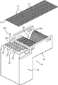
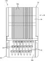
- 1 is an exploded perspective view of an electrical connection assembly according to a first embodiment of the present invention. It is a top view of the connector which comprises the said electrical connection assembly. It is a front view of the connector. It is a perspective view which shows the 1st connection member and the 2nd connection member which were fixed to the 1st terminal and 2nd terminal which comprise the said connector, and its electric wire connection surface. It is a cross-sectional front view which shows the said 1st connection member fixed to the electric wire connection surface of the said 1st terminal. It is a perspective view which shows the state which the said 1st and 2nd connection member was plastically deformed so that it might have a 1st protrusion part and a 2nd protrusion part, respectively.
- FIG. 8 is a front view showing a cross section taken along line VIII-VIII in FIG. 7. It is a perspective view which shows the state by which the 1st electric wire and the 2nd electric wire were mounted on the said 1st and 2nd connection member. It is a cross-sectional front view which shows the state of FIG. It is a perspective view which shows the process of connecting the electric wire connection surface of each terminal of the said connector, and the connection object site
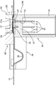
- FIG. 12 is a cross-sectional side view showing the process shown in FIG. 11.
- FIG. 13 is an enlarged view of a region surrounded by a frame line XIII in FIG. 12.
- the perspective view which shows the state by which the conductors of the said 1st and 2nd electric wire were mutually connected through the said 1st and 2nd connection member by the fusion
- FIG. It is a cross-sectional front view which shows the state of FIG. It is a perspective view which shows the state in which the 1st electric wire and the 2nd electric wire were mounted on the said 1st and 2nd connection member, respectively. It is a cross-sectional front view which shows the state of FIG. The perspective view which shows the state by which the conductors of the said 1st and 2nd electric wire were mutually connected through the said 1st and 2nd connection member by the fusion
- the electrical connection assembly includes a plurality of electric wires 10 and a connector CN for connecting the plurality of electric wires 10 to another connector.
- 1 to 3 show the connector CN before the plurality of electric wires 10 are connected.
- Each of the plurality of electric wires 10 includes a conductor 12 and an insulating film 14 covering the conductor 12 as shown in FIGS. 10 and 13.
- the plurality of electric wires 10 are connected to the connector CN in a state of being arranged in parallel to each other with an interval in the electric wire arrangement direction orthogonal to the longitudinal direction.
- the electric wire used in the present invention may be a so-called bare electric wire that does not have the insulating coating 14.
- the plurality of electric wires 10 include a first electric wire 10A and a second electric wire 10B as shown in FIGS. These first and second electric wires 10A and 10B are electric wires adjacent to each other in the electric wire arrangement direction and are electrically connected to each other to form a branch circuit, that is, electric wires to be interconnected. It is. The structure and method for interconnecting the first and second electric wires 10A and 10B will be described in detail later.
- the connector CN includes a plurality of terminals 20 corresponding to each of the plurality of electric wires 10, an insulating housing 30 that collectively holds the plurality of terminals 20, and each of which is made of solder, and is provided to each of the plurality of terminals 20.
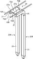
- Each of the plurality of terminals 20 is a male terminal composed of a single long metal plate, and includes a held portion 22, an electrical contact portion 23, and an outer side as shown in FIG.
- a protrusion 24 is provided.
- the held portion 22 is a portion held by the insulating housing 30 as described later.
- the electrical contact portion 23 is a male contact portion and has a shape that can be fitted to the female contact portion of the counterpart terminal. Specifically, it has a shape extending linearly from the held portion 22 in a first direction to be described later.
- the outer protruding portion 24 is a portion that protrudes from the held portion 22 to the opposite side of the electric contact portion 23 and is connected to the corresponding electric wire 10 among the plurality of electric wires 10. The outer protrusion 24 will be described in detail later.
- the plurality of terminals 20 include a first terminal 20A and a second terminal 20B corresponding to the first electric wire 10A and the second electric wire 10B, respectively, as shown in FIG.
- the first terminal 20A and the second terminal 20B are arranged adjacent to each other in the wire arrangement direction.
- the first electric wire 10A includes a first conductor 12A as the conductor
- the second electric wire 10B includes a second conductor 12B as the conductor.
- the insulating housing 30 is formed of an insulating material such as synthetic resin, and integrally includes a terminal holding portion 32, a hood 33, and an electric wire holding portion 34.
- the terminal holding portion 32 is a portion for holding the held portion 22 of each of the plurality of terminals 20, and is in a block shape in the first embodiment.
- the terminal holding portion 32 is configured to allow the electric wires 10 to be connected to the outer protrusions 24 of the plurality of terminals 20 in a conductive manner in a state where the electric wires 10 are arranged at intervals in the electric wire arrangement direction.
- the plurality of terminals 20 are collectively held in an arrangement in which the plurality of terminals 20 are arranged in the wire arrangement direction.
- the terminal holding part 32 holds the held part 22 of the terminal 20 in a state where each terminal 20 penetrates the terminal holding part 32 in a direction parallel to the first direction.
- the first direction is a direction orthogonal to both the longitudinal direction of the electric wire 10 and the electric wire arrangement direction in a state in which the electric wire 10 is connected to the terminal 20, and in the posture shown in FIG. is there. That is, in the posture shown in FIG. 12, a portion of the terminal 20 including the held portion 22 penetrates the terminal holding portion 32 in the vertical direction.
- the held portion 22 may be fixed to the terminal holding portion 32 by press-fitting the held portion 22 into a through hole provided in the terminal holding portion 32, or may be performed using an adhesive or the like. May be.
- each terminal 20 is in a direction opposite to the first direction (shown in FIG. 12) from the held portion 22 with the held portion 22 held by the terminal holding portion 32 as described above. In this posture, it extends downward) and fits in the direction with the female contact portion of the counterpart terminal.
- the hood 33 is integrally connected to the terminal holding portion 32 and has a cylindrical shape that surrounds the electrical contact portion 23 on the outer side in a direction orthogonal to the axial direction of the electrical contact portion 23 (vertical direction in the posture shown in FIG. 12). Make.
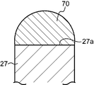
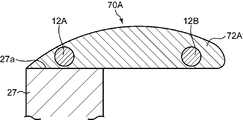
- the outer protrusion 24 of each terminal 20 integrally includes a first protrusion 26 and a second protrusion 27 as shown in FIGS.
- the first protruding portion 26 protrudes from the surface of the terminal holding portion 32 (upper surface 32a in FIG. 13) in the first direction (upward in FIG. 13).
- the second protrusion 27 is a second direction that is closer to the direction parallel to the surface of the terminal holding part 32 than the first direction from the upper end of the first protrusion 26 and is orthogonal to the wire arrangement direction. (In this first embodiment, it extends in the direction parallel to the upper surface 32a; the left-right direction in FIG. 13).
- connection surface 27a is so-called soldered to the connection target portion in a state where the connection target portion, which is a specific portion of the conductor 12 of the electric wire 10, is placed on the connection member 70 (that is, It is a surface that can be electrically connected (using the connection member 70 as a connection medium).
- the electric wire connection surface 27a according to the first embodiment extends in a direction parallel to the upper surface 32a of the terminal holding portion 32.
- the plurality of connection members 70 are fixed to the wire connection surfaces 27a of the plurality of terminals 20, respectively.
- the connection member 70 has a cross-sectional shape that bulges upward from the wire connection surface 27 a and is set on the wire connection surface 27 a so as to extend along the longitudinal direction of the wire 10.
- the plurality of connection members 70 include a first connection member 70 ⁇ / b> A applied to the first terminal 20 ⁇ / b> A and a second connection applied to the second terminal 20 ⁇ / b> B.
- Member 70B is shown in FIGS. 6 and 7, the plurality of connection members 70 include a first connection member 70 ⁇ / b> A applied to the first terminal 20 ⁇ / b> A and a second connection applied to the second terminal 20 ⁇ / b> B.
- the protrusion dimension from which the first protrusion 26 protrudes from the upper surface 32a of the terminal holding part 32 is appropriately set.
- the protruding dimension is a surface of the surface of the second protruding portion 27 that faces the upper surface 32a of the terminal holding portion 32, that is, a surface opposite to the wire connecting surface 27a.
- the second protrusion so that the second protrusion 27 extends in the second direction at a position where the inner side surface (lower surface in FIG. 13) 27b is spaced outward from the upper surface of the terminal holding portion 32 (upper side in FIG. 13).
- the dimension for setting the portion 27 is set.
- the protrusion dimension is set to the same dimension for all the terminals 20. Therefore, the terminal holding part 32 holds the terminal 20 so that the wire connection surfaces 27a of the terminals 20 are arranged on the same plane. Conversely, a specific height difference may be given between the electric wire connection surfaces 27a.
- the arrangement of the plurality of terminals 20 can be freely set.
- the electric wire connection surfaces 27a of the plurality of terminals 20 are arranged at intervals in the electric wire arrangement direction.
- the held portions 22 of the plurality of terminals 20 are held so that the wire connection surfaces 27a of the terminals 20 adjacent to each other in the arrangement direction are arranged with their positions shifted in the longitudinal direction of the wires 10 (vertical direction in FIG. 2). Specifically, in the arrangement shown in FIG.
- a plurality of outer protrusions 24 each having the electric wire connection surface 27a are arranged along three rows arranged in a direction parallel to the longitudinal direction of the electric wire 10, And the position of the electric wire connection surface 27a of the outer protrusion part 24 arrange
- column is each said electric wire arrangement direction with respect to the position of the electric wire connection surface 27a of the outer protrusion part 24 arrange
- the terminal holding portion 32 has a position of the wire connection surface 27a of the first terminal 20A and the wire connection surface of the second terminal 20B.
- the first and second terminals 20A and 20B are held at such positions that the positions are shifted in the longitudinal direction of the first and second electric wires 10A and 10B and the electric wire arrangement direction.
- the electric wire holding part 34 extends from the terminal holding part 32 along a direction parallel to the second direction, and each of the electric wires 10 extends in the posture in which the electric wires 10 extend along the second direction. Hold.
- the electric wire holding part 34 according to the first embodiment has a plurality of parallel electric wire holding grooves 34a corresponding to the electric wires 10, and the electric wires 10 are fitted in the electric wire holding grooves 34a.
- the electric wire 10 is supported from below in the state.
- the first connecting member 70A is provided with a shape including a first protruding portion 72A
- the second connecting member 70B is provided with a shape.
- 72 A of said 1st protrusion parts are the directions which approach the said 2nd electric wire 10B along the direction parallel to the said electric wire arrangement direction from the electric wire connection surface 27a of the said 1st terminal 20A (right direction in FIG. 6 and FIG. 8).
- the second protruding portion 72B extends from the electric wire connection surface 27a of the second terminal 20B toward the first electric wire 10A along a direction parallel to the electric wire arrangement direction (FIG. 6). It is the part that protrudes to the left).
- the protruding length of the first protruding portion 72A is set to a length that allows the second electric wire 10B to be placed on the first protruding portion 72A, as shown in FIGS. Has been.
- the protruding length of the second protruding portion 72B is set to a length that allows the first electric wire 10A to be placed on the second protruding portion 72B, as shown in FIG. Has been.
- the cross-sectional shapes of the first and second connection members 70A and 70B can be freely set.
- the first and second connection members 70A and 70B may have a rectangular cross section that is long in the lateral direction.
- the connector CN further includes a cover 40 as shown in FIG.
- the cover 40 is detachably attached to the insulating housing 30 so as to cover the outer protruding portion 24 of the terminal 20 and the electric wires 10 connected thereto from above.
- the cover 40 according to the first embodiment integrally includes a terminal cover portion 42 that covers the terminal holding portion 32 and an electric wire cover portion 44 that covers the electric wire holding portion 34.
- the electric wire holding portion 34 has a curved portion 36 that is curved so that the upper surface of the electric wire holding portion 34, that is, the surface on which the electric wire holding groove 34 a is formed is recessed downward at the intermediate position in the second direction.
- the lower surface of the wire cover portion 44 of the cover 40 has a curved portion 46 bulging downward corresponding to the curved portion 36.
- the bending portion 46 and the bending portion 36 have a shape capable of restraining the intermediate portion in a state where the intermediate portion of each electric wire 10 is bent downward. It effectively inhibits the tension of the electric wire 10 from acting on the connection portion between the 12 connection target portions and the electric wire connection surface 27a.
- the wire holding part 34 and the cover 40 are not essential in the present invention, and can be omitted. Conversely, when the connection target portion of the conductor 12 of each electric wire 10 is set not in the vicinity of the end of the electric wire 10 but in the intermediate portion in the longitudinal direction, on both sides of the terminal holding portion 32 in the longitudinal direction of the electric wire 10.
- the electric wire holding part 34 and the electric wire cover part 44 of the cover 40 corresponding thereto may be provided.
- the electrical connection assembly includes, for example, the following 1) electric wire preparation step, 2) connector preparation step, 3) terminal connection step and interconnection step (both steps are simultaneously executed in this embodiment), and 4) cutting. It can be manufactured by a method including steps.
- the several electric wire 10 mentioned above is prepared beforehand.
- the plurality of electric wires 10 are prepared such that the insulating coating 14 of each electric wire 10 is made of a specific synthetic resin.
- the specific synthetic resin is a synthetic resin that has an insulating property at room temperature and can be melted or decomposed at the melting temperature (for example, 380 to 400 ° C.) of the solder constituting the connecting member 70.
- the specific synthetic resin polyurethane, polyester, nylon and the like are suitable.
- the thickness of the insulating coating 14 is set to such a thickness that the insulating coating 14 can be removed and the conductor 12 can be exposed by the heating while ensuring an insulating state at room temperature. For the thickness, for example, a dimension approximating the thickness of the insulating coating in a normal enameled wire can be applied.
- This step includes the following 2-1) connecting member applying step, 2-2) terminal setting step, and 2-3) protruding portion forming step.
- connection member application step The connection members 70 are fixed to the electric wire connection surfaces 27a of the plurality of terminals 20 constituting the connector CN.
- the shape of the connecting member 70 at this stage can be freely set.
- the wire connecting surface 70 has a cross-sectional shape such that the central portion of the wire connecting surface 27 a rises in the width direction (direction parallel to the wire arranging direction). 27a is fixed.
- the connection member 70 may be applied to the terminal 20 by fixing the solder constituting the connection member 70 to the electric wire connection surface 27a in a solid state, or a paste-like solder (connection member). 70) may be applied to each electric wire connection surface 27a.
- Terminal setting step is a step of fixing the plurality of terminals 20 to the insulating housing 30, that is, a step of holding the plurality of terminals 20 in the insulating housing 30.
- the terminals 20 are inserted and press-fitted from above into a plurality of through holes formed in advance in the terminal holding portion 32 of the insulating housing 30 (that is, the through holes).
- the held portion 22 is bitten into the inner peripheral surface of the terminal holding portion 32 surrounding the terminal holding portion 32), or the held portion 22 is fixed to the terminal holding portion 32 by other means such as an adhesive.
- the plurality of terminals 20 are fixed to 32 predetermined positions, respectively.
- the terminal setting step may be performed before the connection member applying step. That is, the connection member 70 may be applied in a state where the plurality of terminals 20 are respectively held in the insulating housing 30. However, when the application of the connection member 70 is performed with heating of the connection member 70 (heating exceeding the melting point of the solder), the insulation housing 30 is in a state where the terminals 20 are already held by the insulation housing 30. Therefore, heat resistance sufficient to withstand the heating is required, and the material of the insulating housing 30 is restricted accordingly. Accordingly, the connecting member application step is performed before the terminal setting step, that is, the connection members 70 are applied to the plurality of terminals 20 before the plurality of terminals 20 are set in the insulating housing 30. Is more preferable.
- each connecting member 70 made of solder as described above can be easily generated by pressing a mold having an appropriate shape against the first and second connecting members 70A and 70B, for example. is there.
- the shape of the first and second protrusions 72A and 72B that is, the wire connection surface 27a of the first and second terminals 20A and 20B is parallel to the wire arrangement direction. It is possible to freely set a shape that protrudes in any direction.
- This protruding portion forming step may be performed before or simultaneously with the terminal setting step and the connecting member applying step.
- the protrusions 72A and 72B may be formed after the connection member 70 is applied to each terminal 20 and before the terminal 20 is held by the insulating housing 30, or the first and second protrusions are already formed.
- the first and second connection members 70A and 70B in which the portions 72A and 72B are formed may be fixed to the wire connection surfaces 27a of the first and second terminals 20A and 20B.
- the protruding portion forming step is performed after the connection member applying step and the terminal setting step, that is, the positioning of the plurality of terminals 20 with respect to the insulating housing 30 by holding the plurality of terminals 20 by the insulating housing 30 and Forming the protruding portions 72A and 72B in a state where the plurality of terminals 20 are already positioned means that the protruding portions 72A and 72B and the first and second electric wires 10A to be connected to the protruding portions 72A and 72B. , 10B can be more reliably positioned.
- the protruding portion forming step is performed only on the connection member corresponding to the wire to be interconnected among the plurality of connection members.
- the electrical connection assembly provided by the present invention may include a plurality of interconnected wire pairs (a pair of wires to be interconnected), in which case each interconnected wire is It is preferable that the protruding portion forming step is performed for the corresponding connecting member.
- Terminal connection process and interconnection process In the terminal connection process, the plurality of wires 10 are brought into contact with the plurality of connection members 70 in a state in which the plurality of wires 10 are arranged at intervals in the wire arrangement direction. While the plurality of connection members 70 are heated and melted, the connection target portions set in the respective conductors 12 of the plurality of wires 10 and the corresponding wire connection surfaces 27a are connected to the plurality of connection members. 70, and the interconnecting step includes first and second protruding portions 72A of the first and second connecting members 70A and 70B of the plurality of connecting members 70, By heating and melting 72B, the conductor 12A of the first electric wire 10A and the second electric wire are mediated by the first and second connecting members 70A and 70B. This is a step of connecting the 10B conductor 12B to each other.
- the terminal connection process and the interconnection process are performed simultaneously. Specifically, both the connecting steps are performed by sequentially performing the following 3-1) wire setting work and 3-2) heating work.
- Electric wire setting operation This operation is performed while maintaining the state in which the plurality of electric wires 10 are arranged at intervals in the electric wire arrangement direction as shown in FIG. This is an operation of bringing the connection target portion set in the intermediate direction region into contact with the surfaces of the plurality of connection members 70 in a state where the connection target portion is covered with the insulating coating 14.
- the plurality of electric wires 10 are held at positions on both outer sides of the connection target part, more preferably both ends of the connector CN in the front-rear direction (the second direction and the direction parallel to the electric wire longitudinal direction). This is done by holding the outer position. In the holding, it is preferable that the electric wire 10 is fitted into the protruding portions 72A and 72B while an appropriate tension is applied to each of the plurality of electric wires 10.
- the holding can be performed by, for example, a bobbin around which the plurality of electric wires 10 are wound, a holding tool that holds the electric wires 10 from both sides in a direction orthogonal to both the longitudinal direction and the electric wire arrangement direction, and the like. is there.
- the first connecting member 70A among the plurality of connecting members 70 is a second protruding portion 72A, that is, the second from the wire connecting surface 27a corresponding to the first connecting member 70A.
- a portion protruding in a direction parallel to the electric wire arrangement direction toward the electric wire 10B, and the second connecting member 70B is a second protruding portion 72B, that is, the electric wire connecting surface 27a corresponding to the second connecting member 70B.
- the second electric wire 10 ⁇ / b> B not only contacts the corresponding second connecting member 70 ⁇ / b> B but also from the second connecting member 70 ⁇ / b> B to the first and second It is possible to contact the first protruding portion 72A of the first connecting member 70A at a position shifted in the longitudinal direction of the electric wires 10A and 10B, and the first electric wire 10A corresponds to this. It is possible not only to contact the first connecting member 70A but also to contact the second protruding portion 72B of the second connecting member 70B at a position shifted from the first connecting member 70A in the longitudinal direction. To do.
- connection member 70 is used as an intermediary to electrically connect the connection target portion and the wire connection surface 27a of the terminal 20 corresponding thereto.
- a portion of the insulating coating 14 of each electric wire 10 that covers the connection target portion of the conductor 12 is heated together with the connection member 70, thereby melting the insulating coating 14 covering the connection target portion.
- the removal from the surface of the conductor 12 by disassembly and the conductor 12 exposed by the removal of the insulating coating 14 and the wire connection surface 27a to which the connection member 70 is fixed via the connection member 70). Electrical connection is achieved at the same time. In this way, the terminal connection process for each terminal 20 is executed.
- the pressing and heating of the electric wire 10 against the electric wire connecting surface 27a can be efficiently performed using the heater 50 shown in FIGS.
- the heater 50 has a flat lower surface constituting the heating surface 52.
- the heating surface 52 is pressed against the electric wires 10 set on the electric wire connection surfaces 27a via the connection members 70, that is, the heating surface 52 and the electric wire connection surfaces 27a.
- the heating surface 52 is pressed toward the plurality of wire connection surfaces 27a with the plurality of connection target portions and the connection member 70 respectively sandwiched between the plurality of wire connection surfaces 27a.
- the melting by heating of the connection member 70 by the heater 50 and the melting or decomposition of the insulating coating 14 by heating of the insulating coating 14 covering the connection target site are performed simultaneously. Melting or decomposing the insulating coating 14 allows the insulating coating 14 to be removed from the surface of the conductor 12.
- the terminal holding part 32 of the insulating housing 30 holds the terminals 20 so that the electric wire connection surfaces 27a are arranged on the same plane, that is, the terminals 20 are the plane array terminals.
- the plurality of connecting members 70 are simultaneously and uniformly heated using a single flat heating surface 52, and the connection target portions of the conductors 12 of each wire 10 and the conductor 12 of each wire 10 are Can be performed simultaneously.
- each said wire connection surface 27a is provided in the outer side protrusion part 24 which protrudes on the outer side (in FIG. 13 etc.) of the said terminal holding part 32 from the upper surface 32a of the terminal holding part 32.
- the first connecting member 70A is heated by the heater 50, as shown in FIGS. 14 and 15, the first electric wire 10B out of the second electric wires 10B.
- the insulating coating 14 at the portion of the connecting member 70A that contacts the first protruding portion 72A is also removed, and the conductor 12B of the second electric wire 10B is held in direct contact with the first protruding portion 72A.
- the second connecting member 70B is heated by the heater 50, the insulating coating 14 at a portion of the first electric wire 10A that contacts the second protruding portion 72B of the second connecting member 70B is also provided.
- the conductor 12A of the first electric wire 10A is removed and is held in direct contact with the second protruding portion 72B.
- the first connecting member 70A is fixed to the conductor 12A of the first electric wire 10A corresponding to the first connecting member 70A, and at a position away from the electric wire connecting surface 27a of the first terminal 20A in the electric wire longitudinal direction.
- the first protruding portion 72A is also fixed to the conductor 12B of the second electric wire 10B.
- the second connecting member 70B is fixed to the corresponding conductor 12B of the second electric wire 10B.
- the second protruding portion 72B is also fixed to the conductor 12A of the first electric wire 10A at a position away from the electric wire connecting surface 27a of the second terminal 20B in the electric wire longitudinal direction.
- the first and second electric wires 10A and 10B can be connected to each other by using the first and second connecting members 70A and 70B as they are as connection media without adding any special members.
- An interconnect process is performed.
- a cover 40 as shown in FIG. 16 is attached as necessary to complete the electrical connection assembly. Note that the cutting step and the attachment of the cover 40 are not essential in the present invention, and can be omitted as appropriate.
- the second connecting member 70B in addition to the first protruding portion 72A being formed on the first connecting member 70A and being fixed to the second electric wire 10B, the second connecting member 70B also has the second protruding portion 72A.
- the protruding portion 72B is formed and fixed to the first electric wire 10A, the first and second electric wires 10A and 10B can be interconnected only by connecting the first protruding portion 72A and the second electric wire 10B. Is possible.
- the double connection through the first and second protrusions 72A and 72B significantly improves the reliability of the interconnection.
- the first protruding portion 72A has a shape that extends further in the electric wire arrangement direction than the above shape, thereby being fixed to the conductor of the third electric wire further adjacent to the second electric wire 10B. Is also possible. This makes it possible to interconnect three or more wires via the first connecting member 70A. In other words, the present invention broadly encompasses those in which at least the first and second electric wires are interconnected using the first connecting member.
- a connector CN similar to the connector CN shown in FIGS. 1 to 3 and a plurality of electric wires 10 are used, and a connector preparation process, a terminal connection process, and an interconnection process are performed. It is done in order.
- the first and second connecting members 70A and 70B are connected to the mating electric wires (second electric wires 10B from the respective electric wire connecting surfaces 27a. And the 1st and 2nd protrusion parts 72A and 72B which protrude toward the 1st electric wire 10A) are formed.
- the second embodiment is different from the first embodiment in the following points.
- the wire connection surfaces 27a of the first and second terminals 20A and 20B adjacent in the wire arrangement direction are in a position shifted in the wire longitudinal direction, and the interconnection step.
- the first and second protruding portions 72A and 72B formed on the first and second connection members 70A and 70B are directly fixed to the conductors 12B and 12A of the second and first electric wires 10B and 10A, respectively.
- the first and second terminals 20A and 27B are arranged in a direction parallel to the electric wire arrangement direction, and the first and second protruding portions 72A.
- the first and second electric wires 10A are respectively connected to the first and second connecting members 70A and 70B as shown in FIGS. , 10B, the first and second electric wires 10A, 10B are set.
- the first and second connection members 70A and 70B are heated and melted, whereby the first and second connection members 70A and 70B are integrated with each other, as shown in FIGS.
- a single interconnection member 74 is configured, and the conductors 12A and 12B of the first and second electric wires 10A and 10B are electrically connected to each other through the interconnection member 74.
- first and second connecting members 70A and 70B are not integrated with each other, and the first and second protruding portions 72A and 72B are in contact with each other, so that the interconnection is achieved. Is possible. However, the formation of the interconnection member 74 by the integration dramatically increases the reliability of the interconnection.
- the ends of the first and second protruding portions 72A and 72B may be arranged so as to overlap each other in the thickness direction (the vertical direction in the postures according to the first and second embodiments). Or only the 1st protrusion part 72A of the 1st and 2nd protrusion parts 72A and 72B is formed, and the 1st protrusion part 72A only makes it possible to contact the 2nd connection member 70B.
- the overhang length may be given to the first overhang portion 72A.
- the counterpart to which the first protruding portion 72A is fixed is not limited to the second connecting member 70B, but may be, for example, an appropriate portion of the second terminal 20B (for example, the side surface of the second protruding portion 27). Good.
- the present invention includes the following other forms.
- the shape of the protruding portion formed at least on the first connecting member is not limited to those shown in the first and second embodiments, and is arbitrarily set. Is possible.
- the protruding portion may be provided with a shape for stabilizing the relative position between the protruding portion and the electric wire in contact with the protruding portion, for example, a shape including a groove into which the electric wire can be fitted.
- the direction in which the protruding portion protrudes from the electric wire connection surface is not necessarily limited to the direction parallel to the electric wire arrangement direction.
- the first protruding portion 72A may extend obliquely with respect to the electric wire arrangement direction so that the first protruding portion 72A contacts the second connecting member 70B or the second terminal 20B.
- the first protruding portion 72A can be fixed to the conductor 12B of the second electric wire 10B at a position away from the second connecting member 70B and the second terminal 20B in the electric wire longitudinal direction.
- the first protruding portion 72A may extend obliquely with respect to the electric wire arrangement direction.
- the terminal connection process and the interconnection process may be performed individually instead of simultaneously.
- the first connection member 70A according to the first embodiment is mediated by the first connection member 70A by local heating of a portion located immediately above the wire connection surface 27a of the first terminal 20A.
- the first protruding portion is locally heated by the first protruding portion 72A of the first connecting member 70A.
- the connection between 72A and the conductor 12B of the second electric wire 10B may be performed.
- the terminal connection step may be performed for each terminal 20 individually. That is, the plurality of connection members 70 may be individually heated. Alternatively, when a plurality of connection members 70 exist, the connection members 70 may be heated for each group divided in advance.
- connection between the wire connection surface and the connection target portion the conductor 12 is melted or decomposed simultaneously with the melting of the connection member 70 by heating with a heater.
- the removal from the surface is performed, the removal of the insulating coating 14 may be performed in advance before the heating. That is, the insulating coating is removed in advance before the connecting step by a so-called skinning process so as to expose the connection target portion of the conductor set in each of the plurality of electric wires, and the conductor exposed as described above in the connecting step Soldering with an electric wire connection surface may be performed directly.
- the material constituting the insulating coating does not necessarily have to be melted or decomposed. Needless to say, it is not necessary to remove the insulation coating when each wire is a bare wire.
- the number of wires in the electrical connection assembly according to the present invention is not limited.
- the present invention can be widely applied to an electrical connection assembly including a plurality of electric wires, wherein the plurality of electric wires include at least a first electric wire and a second electric wire (which are to be interconnected). is there.
- an electrical connection assembly including a plurality of wires and connectors, and a desired structure of the plurality of wires can be achieved with a simple structure without significant increase in cost.
- those capable of interconnecting the conductors of an electrical wire and methods that enable the electrical connection assembly to be efficiently manufactured are provided.
- connection member which is a connection medium for connecting the first electric wire and the corresponding first terminal, approaches the second electric wire from the electric wire connection surface of the first terminal.
- connection member By providing a shape that protrudes in the direction, the connection member can be used as a connection medium for connecting the first electric wire and the second electric wire, so that no special member is required. Interconnection of the first electric wire and the second electric wire can be achieved with a simple structure.
- the protruding portion of the first connecting member is directly fixed to the conductor of the second electric wire.
- the first connecting member is directly fixed to both conductors of the first and second electric wires, that is, only the first connecting member is used as a medium for the first and second electric wires.
- the position of the wire connection surface of the first terminal and the position of the wire connection surface of the second terminal are such that the first wire and the second wire are displaced in the longitudinal direction of the first wire.
- the protruding portion of the connection member applied to the first terminal is parallel to the wire arrangement direction from the wire connection surface of the first terminal. It is preferable that it protrudes in any direction and is directly fixed to the conductor of the second electric wire. Accordingly, the first and second terminals are provided with a sufficient distance between the first terminal and the second terminal due to mutual displacement of the positions of the first and second terminals in the longitudinal direction.
- the protruding length of the protruding portion for interconnecting the two electric wires can be kept small.
- the second connecting member has a protruding portion that protrudes in a direction approaching the first electric wire from the electric wire connecting surface of the second terminal.
- the protruding portion of the connecting member may be directly fixed to the conductor of the first electric wire. Such double connection further increases the reliability of the interconnection between the first electric wire and the second electric wire.
- the protruding portion of the first connecting member protrudes in the direction from the electric wire connecting surface of the first terminal toward the second terminal, and is fixed to the second terminal or the second connecting member. It may be a thing. Also in this case, it is possible to connect the first electric wire and the second electric wire to each other through the first connecting member and further the second connecting member.
- first connecting member and the second connecting member can be integrated with each other to form a single interconnect member, for example, by melting them and then solidifying them. This drastically improves the connection reliability as compared with the aspect in which the first and second connection members are simply in contact with each other.
- the method provided by the present invention includes a plurality of electric wires and connectors each including a conductor, and the first electric wire and the second electric wire included in the plurality of electric wires are connected to each other.
- a method for manufacturing a connection assembly wherein the connector includes a plurality of terminals corresponding to each of the plurality of electric wires, the first terminals corresponding to the first electric wires, and the second electric wires.
- a second connection member including a corresponding second terminal, a plurality of connection members each formed of solder and applied to each of the plurality of terminals, the first connection member applied to the first terminal, and the The connection member including the second connection member provided to the second terminal and the plurality of wires in a state in which the plurality of wires are arranged at intervals in the wire arrangement direction orthogonal to the longitudinal direction thereof.
- An insulating housing that collectively holds the plurality of terminals in an arrangement in which the plurality of terminals are arranged in the electric wire arrangement direction so as to be connected to each other.
- connection object set in each conductor of the plurality of electric wires by heating and melting the plurality of connection members while bringing the plurality of electric wires into contact with the plurality of connection members in a state of being arranged
- connection by a simple operation of heating and melting each of the plurality of connecting members, the connection between the plurality of electric wires and the corresponding terminals (terminals) through the plurality of connecting members is performed. Connection) and interconnection between the conductor of the first electric wire and the conductor of the second electric wire through the first connecting member can be efficiently performed.
- the terminal connection step for connection between the first electric wire and the first terminal through the first connection member it is also possible to carry out the interconnection step simultaneously, which can further improve the production efficiency of the electrical connection assembly as compared with the case where the terminal connection step and the interconnection step are performed separately.
- the protrusion is made to protrude from the first connection member by plastically deforming the first connection member in a state where the first connection member is fixed to the electric wire connection surface of the first terminal. It is preferable to include forming a part. In this method, a protruding portion having a preferable shape can be easily formed by plastically deforming the connection member using the characteristics of the solder constituting the connection member.
- the protruding portion is formed after the plurality of terminals are held by the insulating housing. This further ensures the positioning of the protruding portion with respect to the first electric wire.
- the protruding portion of the first connecting member is prepared to have a shape that allows direct contact with the conductor of the second electric wire.
- the protruding portion is It is preferable that the protruding portion is heated and directly fixed to the conductor of the second electric wire in a state of being in direct contact with the second electric wire.
- the first connecting member is directly fixed to the conductor of the second electric wire by a simple operation of heating the protruding portion in a state where the protruding portion and the second electric wire are in contact with each other. That is, it is possible to directly interconnect the first electric wire and the second electric wire with the first connecting member as a medium, thereby obtaining high reliability for the interconnection. it can.
- the position of the wire connection surface of the first terminal and the position of the wire connection surface of the second terminal are shifted from each other in the longitudinal direction of the first wire and the second wire.
- the protruding portion of the connecting member held by the first housing and the second terminal in the insulating housing at a certain position and applied to the first terminal extends from the wire connection surface of the first terminal to the wire arrangement.
- a protruding part is prepared in a direction parallel to the direction, and the protruding part is fixed to the conductor of the second electric wire at a position deviating from the electric wire connecting surface of the second terminal in the longitudinal direction in the interconnection step.
- first and second terminals may be provided with a sufficient distance between the first terminal and the second terminal by the mutual displacement of the positions of the first and second terminals in the longitudinal direction.
- Second wire interconnection Possible to reduce the protrusion length of the protruding portion for are possible.
- an protruding portion that protrudes in a direction in which the second connecting member approaches the first electric wire from the electric wire connecting surface of the second terminal is provided.
- the protruding portion of the second connecting member may be directly fixed to the conductor of the first electric wire in the interconnection step. Such double connection further increases the reliability of the interconnection between the first electric wire and the second electric wire.
- the protruding portion of the first connecting member is prepared to protrude in the direction from the electric wire connecting surface of the first terminal toward the second terminal.
- the protruding portion is It may be fixed to the second terminal or the second connecting member by being heated and melted. Also in this method, the first electric wire and the second electric wire can be connected to each other through the first connecting member and the second connecting member as a simple operation by simply heating the protruding portion. It is possible to connect.
- first connection member and the second connection member are integrated with each other by heating and melting both the first connection member and the second connection member. It is possible to form an interconnection member, thereby connecting the first electric wire and the second electric wire with higher connection reliability than the aspect in which the first and second connection members are simply in contact with each other. can do.
- the second terminal is provided in the second connection member.
- a protruding portion protruding from the electric wire connection surface toward the first connecting member is formed, and the protruding portions are mutually connected by heating both the protruding portions of the first connecting member and the second connecting member. It is also possible to form the interconnection member integrally. According to this method, even when there is a distance between the first terminal and the second terminal, the first electric wire is suppressed while keeping the protruding length of each protruding portion of the first and second connecting members small. And the conductor of the second electric wire can be interconnected with high reliability.
Landscapes
- Engineering & Computer Science (AREA)
- Manufacturing & Machinery (AREA)
- Connections Effected By Soldering, Adhesion, Or Permanent Deformation (AREA)
- Manufacturing Of Electrical Connectors (AREA)
Priority Applications (3)
| Application Number | Priority Date | Filing Date | Title |
|---|---|---|---|
| CN201880008520.3A CN110226262B (zh) | 2017-02-02 | 2018-01-16 | 电连接组件及其制造方法 |
| US16/482,518 US10714842B2 (en) | 2017-02-02 | 2018-01-16 | Electrical connection assembly and method for manufacturing same |
| DE112018000647.6T DE112018000647B4 (de) | 2017-02-02 | 2018-01-16 | Elektrische Verbindungsanordnung und Verfahren zur Herstellung derselben |
Applications Claiming Priority (2)
| Application Number | Priority Date | Filing Date | Title |
|---|---|---|---|
| JP2017-017816 | 2017-02-02 | ||
| JP2017017816A JP6737195B2 (ja) | 2017-02-02 | 2017-02-02 | 電気接続アセンブリ及びその製造方法 |
Publications (1)
| Publication Number | Publication Date |
|---|---|
| WO2018142913A1 true WO2018142913A1 (ja) | 2018-08-09 |
Family
ID=63039650
Family Applications (1)
| Application Number | Title | Priority Date | Filing Date |
|---|---|---|---|
| PCT/JP2018/000932 Ceased WO2018142913A1 (ja) | 2017-02-02 | 2018-01-16 | 電気接続アセンブリ及びその製造方法 |
Country Status (5)
| Country | Link |
|---|---|
| US (1) | US10714842B2 (https=) |
| JP (1) | JP6737195B2 (https=) |
| CN (1) | CN110226262B (https=) |
| DE (1) | DE112018000647B4 (https=) |
| WO (1) | WO2018142913A1 (https=) |
Families Citing this family (3)
| Publication number | Priority date | Publication date | Assignee | Title |
|---|---|---|---|---|
| CN109565137A (zh) | 2016-05-31 | 2019-04-02 | 安费诺有限公司 | 高性能线缆终端装置 |
| JP6614051B2 (ja) * | 2016-07-12 | 2019-12-04 | 株式会社オートネットワーク技術研究所 | 電気接続アセンブリの製造方法 |
| WO2019028373A1 (en) | 2017-08-03 | 2019-02-07 | Amphenol Corporation | CABLE CONNECTOR FOR HIGH SPEED INTERCONNECTIONS |
Citations (5)
| Publication number | Priority date | Publication date | Assignee | Title |
|---|---|---|---|---|
| JPH05206627A (ja) * | 1992-01-29 | 1993-08-13 | Fujitsu Ltd | リード接続用電極及びリード・電極の接続方法 |
| JPH118037A (ja) * | 1997-06-19 | 1999-01-12 | Yazaki Corp | 電線と端子との接続方法 |
| JPH1145744A (ja) * | 1997-05-30 | 1999-02-16 | Yazaki Corp | 電線と端子との接続構造及び接続方法並びに端子 |
| US20110034084A1 (en) * | 2009-08-10 | 2011-02-10 | Ant Precision Industry Co., Ltd. | SATA Electrical Connector and Assembly thereof |
| JP4681910B2 (ja) * | 2005-02-21 | 2011-05-11 | 株式会社アイペックス | 電気コネクタ |
Family Cites Families (4)
| Publication number | Priority date | Publication date | Assignee | Title |
|---|---|---|---|---|
| JP3048485B2 (ja) * | 1993-03-15 | 2000-06-05 | 矢崎総業株式会社 | 端子と電線のビーム溶接方法 |
| DE69818908T2 (de) * | 1997-05-30 | 2004-07-22 | Yazaki Corp. | Verbindungsstruktur zwischen einem Draht und einem Anschlussklemme, Verbindugsverfahren dafür und eine Anschlussklemme |
| JP4684910B2 (ja) | 2006-02-17 | 2011-05-18 | 独立行政法人 造幣局 | 斜めギザを有するコイン状製品の製造方法および製造装置 |
| JP2010146939A (ja) | 2008-12-22 | 2010-07-01 | Sumitomo Electric Ind Ltd | フラットケーブルの半田接続方法 |
-
2017
- 2017-02-02 JP JP2017017816A patent/JP6737195B2/ja not_active Expired - Fee Related
-
2018
- 2018-01-16 US US16/482,518 patent/US10714842B2/en active Active
- 2018-01-16 CN CN201880008520.3A patent/CN110226262B/zh not_active Expired - Fee Related
- 2018-01-16 DE DE112018000647.6T patent/DE112018000647B4/de active Active
- 2018-01-16 WO PCT/JP2018/000932 patent/WO2018142913A1/ja not_active Ceased
Patent Citations (5)
| Publication number | Priority date | Publication date | Assignee | Title |
|---|---|---|---|---|
| JPH05206627A (ja) * | 1992-01-29 | 1993-08-13 | Fujitsu Ltd | リード接続用電極及びリード・電極の接続方法 |
| JPH1145744A (ja) * | 1997-05-30 | 1999-02-16 | Yazaki Corp | 電線と端子との接続構造及び接続方法並びに端子 |
| JPH118037A (ja) * | 1997-06-19 | 1999-01-12 | Yazaki Corp | 電線と端子との接続方法 |
| JP4681910B2 (ja) * | 2005-02-21 | 2011-05-11 | 株式会社アイペックス | 電気コネクタ |
| US20110034084A1 (en) * | 2009-08-10 | 2011-02-10 | Ant Precision Industry Co., Ltd. | SATA Electrical Connector and Assembly thereof |
Also Published As
| Publication number | Publication date |
|---|---|
| JP2018125221A (ja) | 2018-08-09 |
| US10714842B2 (en) | 2020-07-14 |
| JP6737195B2 (ja) | 2020-08-05 |
| CN110226262B (zh) | 2020-09-15 |
| US20200014123A1 (en) | 2020-01-09 |
| DE112018000647B4 (de) | 2023-03-09 |
| CN110226262A (zh) | 2019-09-10 |
| DE112018000647T5 (de) | 2019-10-17 |
Similar Documents
| Publication | Publication Date | Title |
|---|---|---|
| CN102474028A (zh) | 用于柔性扁平电缆的连接结构和连接方法 | |
| WO2018142913A1 (ja) | 電気接続アセンブリ及びその製造方法 | |
| JP6638583B2 (ja) | コネクタ及びこれを備えた電気接続アセンブリ | |
| US10566705B2 (en) | Method for manufacturing electrical connection assembly | |
| CN111133638B (zh) | 电器件和用于制造电器件的绞合线接触机构的方法 | |
| JP6614051B2 (ja) | 電気接続アセンブリの製造方法 | |
| US10804622B2 (en) | Method for manufacturing electrical connection assembly | |
| JP6776918B2 (ja) | コネクタ及びこれを備えた電気接続アセンブリの製造方法 | |
| CN114665299A (zh) | 装配有端子的电线、连接器以及连接器的制造方法 | |
| JP2018125221A5 (https=) | ||
| JP7451048B2 (ja) | 端子製造方法 | |
| JP2018010742A (ja) | コネクタ及びこれを備えた電気接続アセンブリ | |
| CN113745863A (zh) | 导体连接结构 | |
| JP2024126811A (ja) | 端子付き電線製造方法、及び、端子付き電線 | |
| JP2021068656A (ja) | 端子、端子付き電線、及び、端子圧着方法 |
Legal Events
| Date | Code | Title | Description |
|---|---|---|---|
| 121 | Ep: the epo has been informed by wipo that ep was designated in this application |
Ref document number: 18748374 Country of ref document: EP Kind code of ref document: A1 |
|
| 122 | Ep: pct application non-entry in european phase |
Ref document number: 18748374 Country of ref document: EP Kind code of ref document: A1 |