WO2018142807A1 - 車両用携帯機 - Google Patents
車両用携帯機 Download PDFInfo
- Publication number
- WO2018142807A1 WO2018142807A1 PCT/JP2017/046324 JP2017046324W WO2018142807A1 WO 2018142807 A1 WO2018142807 A1 WO 2018142807A1 JP 2017046324 W JP2017046324 W JP 2017046324W WO 2018142807 A1 WO2018142807 A1 WO 2018142807A1
- Authority
- WO
- WIPO (PCT)
- Prior art keywords
- icon
- vehicle
- sensor
- portable device
- touch sensor
- Prior art date
- Legal status (The legal status is an assumption and is not a legal conclusion. Google has not performed a legal analysis and makes no representation as to the accuracy of the status listed.)
- Ceased
Links
Images


Classifications
-
- E—FIXED CONSTRUCTIONS
- E05—LOCKS; KEYS; WINDOW OR DOOR FITTINGS; SAFES
- E05B—LOCKS; ACCESSORIES THEREFOR; HANDCUFFS
- E05B19/00—Keys; Accessories therefor
- E05B19/0082—Keys or shanks being removably stored in a larger object, e.g. a remote control or a key fob
-
- E—FIXED CONSTRUCTIONS
- E05—LOCKS; KEYS; WINDOW OR DOOR FITTINGS; SAFES
- E05B—LOCKS; ACCESSORIES THEREFOR; HANDCUFFS
- E05B49/00—Electric permutation locks; Circuits therefor ; Mechanical aspects of electronic locks; Mechanical keys therefor
- E05B49/002—Keys with mechanical characteristics, e.g. notches, perforations, opaque marks
- E05B49/006—Keys with mechanical characteristics, e.g. notches, perforations, opaque marks actuating opto-electronic devices
-
- E—FIXED CONSTRUCTIONS
- E05—LOCKS; KEYS; WINDOW OR DOOR FITTINGS; SAFES
- E05B—LOCKS; ACCESSORIES THEREFOR; HANDCUFFS
- E05B19/00—Keys; Accessories therefor
-
- E—FIXED CONSTRUCTIONS
- E05—LOCKS; KEYS; WINDOW OR DOOR FITTINGS; SAFES
- E05B—LOCKS; ACCESSORIES THEREFOR; HANDCUFFS
- E05B49/00—Electric permutation locks; Circuits therefor ; Mechanical aspects of electronic locks; Mechanical keys therefor
-
- G—PHYSICS
- G06—COMPUTING OR CALCULATING; COUNTING
- G06F—ELECTRIC DIGITAL DATA PROCESSING
- G06F3/00—Input arrangements for transferring data to be processed into a form capable of being handled by the computer; Output arrangements for transferring data from processing unit to output unit, e.g. interface arrangements
- G06F3/01—Input arrangements or combined input and output arrangements for interaction between user and computer
- G06F3/048—Interaction techniques based on graphical user interfaces [GUI]
- G06F3/0487—Interaction techniques based on graphical user interfaces [GUI] using specific features provided by the input device, e.g. functions controlled by the rotation of a mouse with dual sensing arrangements, or of the nature of the input device, e.g. tap gestures based on pressure sensed by a digitiser
- G06F3/0488—Interaction techniques based on graphical user interfaces [GUI] using specific features provided by the input device, e.g. functions controlled by the rotation of a mouse with dual sensing arrangements, or of the nature of the input device, e.g. tap gestures based on pressure sensed by a digitiser using a touch-screen or digitiser, e.g. input of commands through traced gestures
-
- G—PHYSICS
- G07—CHECKING-DEVICES
- G07C—TIME OR ATTENDANCE REGISTERS; REGISTERING OR INDICATING THE WORKING OF MACHINES; GENERATING RANDOM NUMBERS; VOTING OR LOTTERY APPARATUS; ARRANGEMENTS, SYSTEMS OR APPARATUS FOR CHECKING NOT PROVIDED FOR ELSEWHERE
- G07C9/00—Individual registration on entry or exit
- G07C9/00174—Electronically operated locks; Circuits therefor; Nonmechanical keys therefor, e.g. passive or active electrical keys or other data carriers without mechanical keys
- G07C9/00944—Details of construction or manufacture
-
- H—ELECTRICITY
- H01—ELECTRIC ELEMENTS
- H01H—ELECTRIC SWITCHES; RELAYS; SELECTORS; EMERGENCY PROTECTIVE DEVICES
- H01H36/00—Switches actuated by change of magnetic field or of electric field, e.g. by change of relative position of magnet and switch, by shielding
-
- H—ELECTRICITY
- H03—ELECTRONIC CIRCUITRY
- H03K—PULSE TECHNIQUE
- H03K17/00—Electronic switching or gating, i.e. not by contact-making and –breaking
- H03K17/94—Electronic switching or gating, i.e. not by contact-making and –breaking characterised by the way in which the control signals are generated
- H03K17/96—Touch switches
- H03K17/962—Capacitive touch switches
- H03K17/9622—Capacitive touch switches using a plurality of detectors, e.g. keyboard
-
- H—ELECTRICITY
- H05—ELECTRIC TECHNIQUES NOT OTHERWISE PROVIDED FOR
- H05K—PRINTED CIRCUITS; CASINGS OR CONSTRUCTIONAL DETAILS OF ELECTRIC APPARATUS; MANUFACTURE OF ASSEMBLAGES OF ELECTRICAL COMPONENTS
- H05K1/00—Printed circuits
- H05K1/02—Details
- H05K1/0275—Security details, e.g. tampering prevention or detection
-
- G—PHYSICS
- G07—CHECKING-DEVICES
- G07C—TIME OR ATTENDANCE REGISTERS; REGISTERING OR INDICATING THE WORKING OF MACHINES; GENERATING RANDOM NUMBERS; VOTING OR LOTTERY APPARATUS; ARRANGEMENTS, SYSTEMS OR APPARATUS FOR CHECKING NOT PROVIDED FOR ELSEWHERE
- G07C9/00—Individual registration on entry or exit
- G07C9/00174—Electronically operated locks; Circuits therefor; Nonmechanical keys therefor, e.g. passive or active electrical keys or other data carriers without mechanical keys
- G07C9/00182—Electronically operated locks; Circuits therefor; Nonmechanical keys therefor, e.g. passive or active electrical keys or other data carriers without mechanical keys operated with unidirectional data transmission between data carrier and locks
- G07C2009/00261—Electronically operated locks; Circuits therefor; Nonmechanical keys therefor, e.g. passive or active electrical keys or other data carriers without mechanical keys operated with unidirectional data transmission between data carrier and locks the keyless data carrier having more than one function
-
- H—ELECTRICITY
- H03—ELECTRONIC CIRCUITRY
- H03K—PULSE TECHNIQUE
- H03K2217/00—Indexing scheme related to electronic switching or gating, i.e. not by contact-making or -breaking covered by H03K17/00
- H03K2217/94—Indexing scheme related to electronic switching or gating, i.e. not by contact-making or -breaking covered by H03K17/00 characterised by the way in which the control signal is generated
- H03K2217/96—Touch switches
- H03K2217/96042—Touch switches with illumination
- H03K2217/96046—Key-pad combined with display, back-lit
-
- H—ELECTRICITY
- H03—ELECTRONIC CIRCUITRY
- H03K—PULSE TECHNIQUE
- H03K2217/00—Indexing scheme related to electronic switching or gating, i.e. not by contact-making or -breaking covered by H03K17/00
- H03K2217/94—Indexing scheme related to electronic switching or gating, i.e. not by contact-making or -breaking covered by H03K17/00 characterised by the way in which the control signal is generated
- H03K2217/96—Touch switches
- H03K2217/9607—Capacitive touch switches
- H03K2217/960785—Capacitive touch switches with illumination
- H03K2217/96079—Capacitive touch switches with illumination using a single or more light guides
Definitions
- the present disclosure relates to a portable device for a vehicle used for, for example, remote operation of locking / unlocking of a vehicle door and remote operation of opening / closing of a vehicle door.
- a control signal corresponding to the currently selected icon is displayed on the vehicle. Is transmitted from the portable device to the in-vehicle device mounted on the vehicle.
- the present disclosure has been made based on this circumstance, and the purpose of the present disclosure is to display a plurality of icons on the display unit, and easy operation until a control signal is transmitted to the in-vehicle device. It is to provide a portable device for a vehicle.
- a portable device for a vehicle is a portable device for a vehicle that is carried by a user of a vehicle and transmits a control signal to the in-vehicle device mounted on the vehicle, and includes an acceleration sensor and an instruction to the in-vehicle device.
- a display unit that displays an icon that represents a display control unit that displays an icon on the display unit when it is detected that acceleration equal to or greater than the activation threshold is generated in the portable device for the vehicle based on a signal output from the acceleration sensor, In a state where the touch sensor for selecting and operating the icon displayed on the display unit, the pressure sensor for detecting the pressing force at the icon selection position that is the position for selecting the icon by the touch sensor, and the icon are selected, A transmission control unit that performs a process of transmitting a control signal corresponding to the currently selected icon based on the detection of the pressing force by the pressure sensor.
- the display control unit displays an icon on the display unit based on the detection that the acceleration equal to or higher than the activation threshold is generated in the vehicular portable device. Therefore, the user can display the icon on the display unit by simply taking out the portable device for the vehicle from the bag or pocket without performing an operation such as pressing an ON switch.
- the pressure sensor provided in the vehicle portable device is adapted to detect the pressing force at the icon selection position, and the transmission control unit selects based on the detection of the pressing force by the pressure sensor.
- a control signal corresponding to the icon inside is transmitted. Therefore, if the user selects an icon and then performs a pressing operation at that position, the control signal corresponding to the currently selected icon can be transmitted. That is, the user can perform an operation of transmitting the control signal at the position of the finger as it is following the operation of selecting the icon.
- the icon can be displayed on the display unit simply by taking the portable device for the vehicle out of the bag or pocket, and the control signal can be displayed at the position of the finger as it is following the operation of selecting the icon. Can be performed. Therefore, the operation until the control signal is transmitted to the in-vehicle device becomes easy.
- FIG. 1 is a plan view of a portable device
- FIG. 2 is an exploded perspective view of the portable device
- FIG. 3 is a block diagram showing the electrical configuration of the portable device
- FIG. 4 is a flowchart showing processing executed by sensor control and communication control.
- FIG. 5 is a flowchart showing processing executed by sensor control and communication control following FIG.
- FIG. 1 is a plan view of a vehicle portable device (hereinafter simply referred to as a portable device) 1 to which the present disclosure is applied.
- the portable device 1 is carried by a user of the vehicle and is used for remote operation of the vehicle such as locking and unlocking of a vehicle door.
- the portable device 1 has a substantially rectangular shape in a plan view as shown in FIG.
- the display unit 10 includes a message display area 11 for displaying a message and an icon display area 13 for displaying an icon 12.
- “HELLO” is displayed in the message display area 11
- five icons 12 a, 12 b, 12 c, 12 d, and 12 e are displayed in different positions in the icon display area 13.
- the icon 12 is a figure representing an instruction for the in-vehicle device mounted on the vehicle.
- the in-vehicle device performs vehicle door lock / unlock control, door open / close control, and the like.
- the icon 12a is an icon indicating the lock of the vehicle door.
- the icon 12b is an icon indicating unlocking of the vehicle door.
- the icon 12c is an icon indicating opening / closing of the electric sliding door on the right side of the vehicle.
- the icon 12d is an icon indicating opening / closing of the electric sliding door on the left side of the vehicle.
- the icon 12e is an icon indicating opening / closing of the back door of the vehicle.
- a control signal corresponding to the selected icon 12 is transmitted to the in-vehicle device.
- the number of icons 12 and the instruction content indicated by the icons 12 are not limited to those described above. In addition to the contents described above, engine start, opening / closing of a window, and the like may be used.
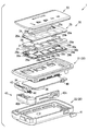
- FIG. 2 is an exploded perspective view of the portable device 1.
- the internal configuration of the portable device 1 will be described with reference to FIG.
- the portable device 1 includes an upper cover 21 and a lower cover 22.
- the material of the upper cover 21 and the lower cover 22 is made of resin.
- the material of the upper cover 21 and the lower cover 22 may be the same or different.
- the upper cover 21 and the lower cover 22 are fitted to each other at the outer peripheral portion to constitute the housing 20.
- the housing 20 has a housing space inside, and various components are housed in the housing 20.
- a display cover 23 serving as a display surface is arranged on the upper side of the upper cover 21, that is, on the surface of the upper cover 21 opposite to the lower cover 22.
- a recess for fitting the display cover 23 is formed on the surface of the upper cover 21 opposite to the lower cover 22, and the display cover 23 is fitted into this recess.
- the material of the display cover 23 is made of acrylic. However, other materials such as polycarbonate and glass can be used.
- the display unit 10 described above is a partial area of the display cover 23.
- the message display area 11 is light transmissive.
- a display 24 is arranged on the back side of the message display area 11, and light representing various messages displayed on the display 24 can be seen from the outside of the portable device 1 through the message display area 11.
- a light transmission area is formed in the shape of the icon 12.
- LEDs 28a, 28b, 28c, 28d, and 28e and light guides 29a, 29b, 29c, 29d, and 29e are arranged on the back surface of the icon display area 13 via the sensor sheet 25 and the like.
- the five LEDs 28a, 28b, 28c, 28d, and 28e are not distinguished from each other, they are described as the LED 28, and when the five light guides 29a, 29b, 29c, 29d, and 29e are not distinguished from each other, they are described as the light guide 29.
- the light emitted from the LED 28 is projected onto the icon 12 through the light guide 29, so that the icon 12 can be visually recognized from the outside of the portable device 1.
- a portion of the display cover 23 that is not the message display area 11 and the icon display area 13 is light-shielding.
- an accommodation space is also formed between the display cover 23 and the upper cover 21.
- a display 24, a sensor sheet 25, a spacer 26, a flexible printed circuit board (FPC) 27, and the like are accommodated.
- a display 24 and a sensor sheet 25 are arranged side by side at substantially the same height.
- the display 24 is, for example, an organic EL display.
- Various characters such as “HELLO” described above are displayed on the display 24.
- a spacer 26 is disposed on the back surface of the display 24 and the sensor sheet 25, and an FPC 27 is disposed on the back surface of the spacer 26.
- the FPC 27 is fixed to the bottom surface of the upper cover 21 with double-sided tape or the like.
- an LED 28, a light guide 29, a lower sensor 30, and an acceleration sensor 31 are fixed on the upper surface on the display cover 23 side.
- a sensor control IC 32 (see FIG. 3) is mounted on the lower surface of the FPC 27.
- Lower sensors 30a, 30b, 30c, 30d, and 30e are formed on the lower FPC 27 of the light guides 29a, 29b, 29c, 29d, and 29e, respectively. When the five lower sensors 30a, 30b, 30c, 30d, and 30e are not distinguished, they are described as the lower sensor 30.
- the lower sensor 30 is a transparent capacitive touch sensor like the sensor sheet 25, and corresponds to a second capacitive touch sensor.
- the spacer 26 has a light guide 29 portion as a through hole. Therefore, the lower sensor 30 faces the sensor sheet 25 with the light guide 29 interposed therebetween. In addition, a gap exists between the light guide 29 and the sensor sheet 25.
- the sensor sheet 25 bends downward according to the bending of the display cover 23.
- the gap between the light guide 29 and the sensor sheet 25 is narrowed and the capacitance detected by the lower sensor 30 changes, the lower sensor 30 is pressed by the user's finger against the display cover 23. Can be detected. That is, in the configuration in which the sensor sheet 25 and the lower sensor 30 are arranged on the back surface of the display cover 23, the position where the icon 12 of the display cover 23 is displayed is pressed by the output of the lower sensor 30.
- a pressure-sensitive sensor 33 is detected.
- the position where the icon 12 is displayed on the display cover 23 is an icon selection position where the icons 12a to 12e are selected by the touch sensor units 25a to 25e.
- the communication board 34 is arranged in a housing space formed by the upper cover 21 and the lower cover 22.
- a connector 35 (see FIG. 3) is mounted on the back surface of the communication board 34.
- the communication board 34 and the FPC 27 are electrically connected via the connector 35. Therefore, a part of the components mounted on the communication board 34 can be mounted on the FPC 27. Conversely, some of the components mounted on the FPC 27 can be mounted on the communication board 34.
- a battery 36 and a communication control IC 37 are mounted on the back surface of the communication board 34. Since the communication board 34 and the FPC 27 are electrically connected by the connector 35, the power of the battery 36 is also supplied to the electrical components mounted on the FPC 27.
- the battery 36 is a button type battery in this embodiment.
- the communication control IC 37 performs control signal transmission control and the like.
- an RF antenna 38 and an LF antenna 39 are also mounted on the communication board 34.
- the RF antenna 38 is an antenna for transmitting radio waves in the RF band such as 315 MHz.
- the LF antenna 39 is an antenna for receiving LF band radio waves such as 135 kHz.
- a tactile switch 40 is mounted on the side surface of the communication board 34.
- the tactile switch 40 can be pushed from the outside of the portable device 1 via the knob 41 disposed on the side surface of the lower cover 22.
- the tactile switch 40 is a switch that is turned on only when pressed.
- an emergency key 42 is also accommodated in the housing space of the housing 20.
- the emergency key 42 is a mechanical key that is inserted into a key cylinder provided in the vehicle and directly locks and unlocks the vehicle door, trunk, and the like.
- the emergency key 42 can be used as an emergency when the communication function of the portable device 1 is disabled due to battery exhaustion.
- the emergency key 42 includes a key part 42a inserted into the key cylinder and a grip part 42b gripped by the user when the key part 42a is inserted into the key cylinder.
- the grip portion 42 b constitutes a part of the outer shape of the portable device 1, specifically, a part of the lower side surface of the portable device 1.
- the release hook 43 and the spring 44 function as a holding mechanism that holds the emergency key 42 in the portable device 1.
- the release hook 43 engages with a part of the emergency key 42 when the release hook 43 is in the locked position by the biasing force of the spring 44.
- the release hook 43 is moved by the user in a direction opposite to the direction urged by the spring 44, the engagement between the emergency key 42 and the release hook 43 is released, and the emergency key 42 is pulled out from the portable device 1. It becomes possible.
- FIG. 3 is a diagram showing an electrical configuration of the portable device 1.
- the touch sensor units 25a to 25e, the lower sensors 30a to 30e, the LEDs 28a to 28e, the acceleration sensor 31, and the display 24 are connected to a sensor control IC 32.
- the RF antenna 38, the LF antenna 39, and the tactile switch 40 are connected to the communication control IC 37.
- the battery 36 is mounted on the communication board 34. However, since the communication board 34 and the FPC 27 are connected to each other via the connector 35, the power from the battery 36 is also supplied to various electronic components executed on the FPC 27.
- Both the sensor control IC 32 and the communication control IC 37 are computers including a CPU, a ROM, a RAM, and the like, and are connected to each other by a plurality of signal lines and a connector 35.
- the sensor control IC 32 detects that a touch operation has been performed on the icons 12a to 12e based on signals supplied from the touch sensor units 25a to 25e. Further, it is detected that the icons 12a to 12e are pressed based on signals supplied from the lower sensors 30a to 30e.
- the sensor control IC 32 outputs a signal indicating that to the communication control IC 37 when it is detected that the icon 12a to 12e is further pressed after the selection operation.
- the sensor control IC 32 performs drive control of the LEDs 28a to 28e and display control of the display 24. Therefore, the sensor control IC 32 functions as a display control unit.
- the LEDs 28a to 28e are turned on and predetermined characters are displayed on the display 24.
- a state in which power is not supplied to the touch sensor units 25a to 25e and the lower sensors 30a to 30e is a sleep state.
- the communication control IC 37 may execute part or all of the functions of the sensor control IC 32 described above. Conversely, part or all of the functions of the communication control IC 37 may be executed by the sensor control IC 32.
- the sensor control IC 32 controls whether the portable device 1 is activated or sleep.
- the communication control IC 37 acquires a signal indicating that the icon 12 has been pressed from the sensor control IC 32, the communication control IC 37 transmits a radio wave representing a control signal determined according to the pressed icon 12 from the RF antenna 38. Therefore, the communication control IC 37 functions as a transmission control unit.
- the communication control IC 37 demodulates the radio wave received by the LF antenna 39 and sequentially determines whether or not the request signal from the in-vehicle device has been received. If it is determined that the request signal has been received, a response signal in response to the request signal is generated and transmitted from the RF antenna 38.
- the sensor control IC 32 shifts the portable device 1 to the activated state.
- the tactile switch 40 is pressed for a short time in the activated state, the portable device 1 is shifted to the sleep state.
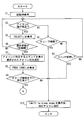
- FIG. 4 is a flowchart showing processing executed by the sensor control IC 32 and the communication control IC 37. Since the sensor control IC 32 and the communication control IC 37 are connected to each other, either the sensor control IC 32 or the communication control IC 37 may execute the processing of each step shown in FIG. Further, the processing in each step may be executed by the sensor control IC 32 and the communication control IC 37 sharing the processing. For example, in FIG. 4, step S10 is executed by the communication control IC 37, and the other steps are executed by the sensor control IC 32.
- the process shown in FIG. 4 is started when the portable device 1 is activated from the sleep state.
- the sleep state when the acceleration detected by the acceleration sensor 31 is equal to or greater than the activation threshold or when the tactile switch 40 is pressed for a short time, the state transits to the activation state.
- step When transitioning to the activation state, first, at the time of step (hereinafter, step is omitted) S1, a display at the time of activation is performed.
- a startup character string set as a character string to be displayed at startup is displayed on the display 24.
- the startup character string is, for example, “HELLO!” Or “HELLO! STAND READY!”.
- all the icons 12 are lit on the display at startup.
- the brightness of the icon 12 at the time of activation is set lower than the brightness when one icon 12 is selected.
- the brightness of the icon 12 at the time of activation is set to 20% of the brightness when one icon 12 is selected.
- the touch sensor units 25a to 25e can detect that a finger or the like has touched the icon 12, and the pressure-sensitive sensor 33 can detect that the portion of the icon 12 is pressed.
- S2 it is determined whether or not a finger or the like has approached the icon 12. This determination is performed to determine whether an operating body such as a finger touches a portion of the display cover 23 where the icon 12 is displayed or approaches a distance close thereto. This determination is made based on the magnitude of the capacitance represented by the signals output from the touch sensor units 25a to 25e.
- S ⁇ b> 3 it is determined whether or not the time during which no operation is continued has become the sleep time or longer.
- the sleep time is a time set as appropriate, and is, for example, 5 seconds or 10 seconds. If judgment of S3 is YES, it will progress to S10.
- the portable device 1 enters a sleep state. The reason for setting the sleep state is to suppress power consumption.
- S3 If the determination in S3 is NO, the process proceeds to S4. In S4, it is determined whether or not the tactile switch 40 has been pressed for a short time. Since the process proceeds to S10 even when the determination in S4 is YES, the portable device 1 enters a sleep state.
- a command corresponding to the selected icon 12 is displayed on the display 24. If the selected icon 12 is an icon 12a indicating that the vehicle door is locked, “LOCK” is displayed on the display 24, for example. Further, only the selected icon 12 is turned on, the other icons 12 are turned off, and the brightness of the selected icon 12 is set to the maximum value.
- S8 “PUSH ICON!” Which is a message indicating the next operation to be performed is displayed on the display 24.
- S9 it is determined whether or not the selected icon 12 has been pressed by the sleep time.
- the sleep time is the same time as S3. If judgment of S9 is NO, it will progress to S10.
- shift to sleep mode which is a message indicating a transition to the sleep state, is displayed on the display 24. Thereafter, the display 24 is turned off.
- the icon 12 is also turned off. That is, the display unit 10 is turned off.
- S9 determines whether the determination in S9 is YES. If the determination in S9 is YES, the process proceeds to S11 shown in FIG. In S 11, the pressed icon 12 is blinked and “sending” is displayed on the display 24. “Sending” is a message indicating that the control signal is in a standby state for transmission. Note that this message may blink as with the icon 12.
- S12 it is determined whether or not a cancel operation has been performed. Specifically, the cancel operation is an operation of pressing the tactile switch 40 for a short time. If judgment of S12 is YES, it will progress to S13. In S ⁇ b> 13, “cancel” which is a message indicating that the pressing operation of the icon 12 is canceled is displayed on the display 24. After executing S13, the process proceeds to S17, and the portable device 1 is put into a sleep state without transmitting a control signal.
- S14 it is determined whether or not the transmission time has come.
- the transmission time is determined by the number of blinks of the icon 12 or the elapsed time from the time when the icon 12 is pressed. For example, the time when the icon 12 blinks five times can be set as the transmission time. Further, the time when 3 to 5 seconds have elapsed from the time when the icon 12 is pressed can be set as the transmission time. If judgment of S14 is NO, it will return to S12. On the other hand, if the determination in S14 is YES, the process proceeds to S15.
- a control signal instructing execution of a command corresponding to the pressed icon 12 is transmitted to the in-vehicle device.
- “Transmission complete”, which is a message indicating that the transmission of the command is completed, is displayed on the display 24. Further, the currently selected icon 12 is blinked. The number of blinks is, for example, once during the display of the message and three times after the message has been displayed.
- the system waits until the transmission time and allows the cancel operation until the transmission time, so that the user has noticed that the operation should not have been performed after pressing the icon 12.
- the transmission of the control signal can be canceled. For example, when the user presses the icon 12e for instructing opening / closing of the back door of the vehicle, but when the back door of the vehicle is opened after the pressing operation, the back door is hit, and the back door is opened. It is possible to cancel transmission of a control signal instructing.
- the portable device 1 executes S ⁇ b> 1 and detects an icon on the display unit 10 when it is detected that an acceleration equal to or greater than the activation threshold is generated in the portable device 1 based on the acceleration signal output from the acceleration sensor 31. 12 is displayed. Therefore, the user can display the icon 12 on the display unit 10 by simply removing the portable device 1 from the bag or pocket without performing an operation such as pressing an on switch.
- a pressure sensitive sensor 33 for detecting a pressing force at the icon selection position is provided.
- a control signal instructing execution of the command is transmitted to the in-vehicle device. Therefore, the user touches the icon 12 to select the icon 12, and then performs a pressing operation as it is, thereby transmitting a control signal instructing execution of a command corresponding to the selected icon 12 to the in-vehicle device. can do. That is, the user can perform an operation of transmitting the control signal at the position of the finger as it is after the operation of selecting the icon 12.
- the portable device 1 of the present embodiment when used, the user only needs to take out the portable device 1 from the bag or pocket and press the button once until the control signal is transmitted to the vehicle-mounted device. Since a similar operation is sufficient, an operation until a control signal is transmitted to the in-vehicle device becomes easy.
- the selection operation of the icon 12 itself is performed by the capacitive touch sensor units 25a to 25e. Therefore, even if the portable device 1 placed in the bag is pressed, it is possible to suppress the icon 12 being selected unintentionally and the control signal being transmitted.
- the portable device 1 of the present embodiment configures the pressure-sensitive sensor 33 with a configuration in which the lower sensor 30 is disposed on the back surface of the sensor sheet 25. That is, since the sensor sheet 25 is also used as a component of the pressure sensor 33, the pressure sensor 33 can be configured at low cost.
- the portable device 1 enters the sleep state without waiting for the sleep time when the control signal is transmitted. Thereby, power saving can be achieved as compared with the case where the sleep state is entered after waiting for the sleep time to elapse.
- the display unit 10 of the portable device 1 includes a message display area 11 at a place different from the icon display area 13.
- Various messages are displayed in the message display area 11.
- the message display area 11 displays “Transmission complete”, which is a message indicating that a control signal has been transmitted. The user can recognize that the pressing operation has been performed by displaying this message in the message display area 11 even though it is difficult to recognize that the pressing operation has been performed from the touch of the finger.
- the five lower sensors 30a to 30e are provided corresponding to the five touch sensor units 25a to 25e provided to detect which icon 12 is selected. However, which icon 12 is selected can be detected by the touch sensor units 25a to 25e. Therefore, the lower sensor 30 does not need to be able to detect which icon 12 corresponds to the pressing operation.
- the lower sensor 30 can detect a change in capacitance with the sensor sheet 25 regardless of which part of the five icon selection positions is pressed on the display cover 23, the lower sensor 30 according to the above-described embodiment. A small number is also acceptable.
- Modification 2 The message displayed on the display 24 is not limited to the message described in the above embodiment. For example, “SELECT ICON!” May be displayed instead of “SELECT!”. Further, instead of “PUSH ICON!”, “PUSH” may be simply displayed. Further, “complete” may be displayed instead of “Transmission complete”. Of course, other messages may be displayed.
- the capacitive touch sensor is provided as the touch sensor.
- a touch sensor other than the capacitive touch sensor may be used.
- a touch sensor based on the principle of an ultrasonic surface acoustic wave method, an acoustic pulse recognition method, an infrared light shielding method, or the like may be used. These touch sensors are systems that do not have mechanical intermittent contacts.
- the pressure-sensitive sensor 33 does not need to have a structure in which two capacitive touch sensors are stacked, and a sensor that detects pressure by another method, such as a sensor that detects pressure by a change in resistance value, is used. You can also.
Landscapes
- Engineering & Computer Science (AREA)
- General Engineering & Computer Science (AREA)
- Theoretical Computer Science (AREA)
- Physics & Mathematics (AREA)
- General Physics & Mathematics (AREA)
- Human Computer Interaction (AREA)
- Computer Security & Cryptography (AREA)
- Microelectronics & Electronic Packaging (AREA)
- Manufacturing & Machinery (AREA)
- User Interface Of Digital Computer (AREA)
- Lock And Its Accessories (AREA)
Priority Applications (3)
| Application Number | Priority Date | Filing Date | Title |
|---|---|---|---|
| CN201780085398.5A CN110249101B (zh) | 2017-02-03 | 2017-12-25 | 车辆用便携设备 |
| DE112017006989.0T DE112017006989T5 (de) | 2017-02-03 | 2017-12-25 | Tragbare fahrzeugvorrichtung |
| US16/509,579 US11441335B2 (en) | 2017-02-03 | 2019-07-12 | Vehicular portable device |
Applications Claiming Priority (2)
| Application Number | Priority Date | Filing Date | Title |
|---|---|---|---|
| JP2017-018666 | 2017-02-03 | ||
| JP2017018666A JP6729433B2 (ja) | 2017-02-03 | 2017-02-03 | 車両用携帯機 |
Related Child Applications (1)
| Application Number | Title | Priority Date | Filing Date |
|---|---|---|---|
| US16/509,579 Continuation US11441335B2 (en) | 2017-02-03 | 2019-07-12 | Vehicular portable device |
Publications (1)
| Publication Number | Publication Date |
|---|---|
| WO2018142807A1 true WO2018142807A1 (ja) | 2018-08-09 |
Family
ID=63040489
Family Applications (1)
| Application Number | Title | Priority Date | Filing Date |
|---|---|---|---|
| PCT/JP2017/046324 Ceased WO2018142807A1 (ja) | 2017-02-03 | 2017-12-25 | 車両用携帯機 |
Country Status (5)
| Country | Link |
|---|---|
| US (1) | US11441335B2 (enExample) |
| JP (1) | JP6729433B2 (enExample) |
| CN (1) | CN110249101B (enExample) |
| DE (1) | DE112017006989T5 (enExample) |
| WO (1) | WO2018142807A1 (enExample) |
Cited By (1)
| Publication number | Priority date | Publication date | Assignee | Title |
|---|---|---|---|---|
| CN111946197A (zh) * | 2020-08-26 | 2020-11-17 | 成都龙翔达科技有限公司 | 一种带有双段式柜门设计的智能保险柜 |
Families Citing this family (5)
| Publication number | Priority date | Publication date | Assignee | Title |
|---|---|---|---|---|
| DE102017115816A1 (de) * | 2017-07-13 | 2019-01-17 | Witte Automotive Gmbh | System mit Tür, Türschloss und Funkschlüssel |
| IT202000019543A1 (it) * | 2020-08-06 | 2022-02-06 | Goffi Alberto Mario | Sistema di controllo di accessi e/o presenze |
| JP7690366B2 (ja) * | 2021-09-30 | 2025-06-10 | トヨタ自動車株式会社 | 携帯機、運転支援システム、制御方法、及び制御プログラム |
| CN115431759A (zh) * | 2022-01-14 | 2022-12-06 | 北京车和家汽车科技有限公司 | 车载显示装置、车辆方向盘总成及车辆 |
| FR3141030A1 (fr) * | 2022-10-13 | 2024-04-19 | Faurecia Interieur Industrie | Film multicouche sensible au toucher et à la pression |
Citations (3)
| Publication number | Priority date | Publication date | Assignee | Title |
|---|---|---|---|---|
| JPH0459270U (enExample) * | 1990-09-28 | 1992-05-21 | ||
| JP2015181055A (ja) * | 2015-06-18 | 2015-10-15 | Kddi株式会社 | 触覚対象画像の奥行き・高低に応じた触覚振動を付与可能なユーザインタフェース装置、触覚振動付与方法及びプログラム |
| JP2016188526A (ja) * | 2015-03-30 | 2016-11-04 | 株式会社デンソー | 車両用携帯機 |
Family Cites Families (5)
| Publication number | Priority date | Publication date | Assignee | Title |
|---|---|---|---|---|
| US8768286B2 (en) * | 2001-10-24 | 2014-07-01 | Mouhamad Ahmad Naboulsi | Hands on steering wheel vehicle safety control system |
| JP4301303B2 (ja) | 2007-02-13 | 2009-07-22 | 株式会社デンソー | 電子キーシステムの携帯機 |
| JPWO2014049794A1 (ja) * | 2012-09-27 | 2016-08-22 | パイオニア株式会社 | 電子機器 |
| CN105741538A (zh) * | 2016-03-31 | 2016-07-06 | 郑州天迈科技股份有限公司 | 一种公交车辆快速调度系统及其调度方法 |
| JP6340051B2 (ja) | 2016-09-29 | 2018-06-06 | 株式会社ソフイア | 遊技機 |
-
2017
- 2017-02-03 JP JP2017018666A patent/JP6729433B2/ja not_active Expired - Fee Related
- 2017-12-25 CN CN201780085398.5A patent/CN110249101B/zh not_active Expired - Fee Related
- 2017-12-25 DE DE112017006989.0T patent/DE112017006989T5/de not_active Withdrawn
- 2017-12-25 WO PCT/JP2017/046324 patent/WO2018142807A1/ja not_active Ceased
-
2019
- 2019-07-12 US US16/509,579 patent/US11441335B2/en active Active
Patent Citations (3)
| Publication number | Priority date | Publication date | Assignee | Title |
|---|---|---|---|---|
| JPH0459270U (enExample) * | 1990-09-28 | 1992-05-21 | ||
| JP2016188526A (ja) * | 2015-03-30 | 2016-11-04 | 株式会社デンソー | 車両用携帯機 |
| JP2015181055A (ja) * | 2015-06-18 | 2015-10-15 | Kddi株式会社 | 触覚対象画像の奥行き・高低に応じた触覚振動を付与可能なユーザインタフェース装置、触覚振動付与方法及びプログラム |
Cited By (1)
| Publication number | Priority date | Publication date | Assignee | Title |
|---|---|---|---|---|
| CN111946197A (zh) * | 2020-08-26 | 2020-11-17 | 成都龙翔达科技有限公司 | 一种带有双段式柜门设计的智能保险柜 |
Also Published As
| Publication number | Publication date |
|---|---|
| JP6729433B2 (ja) | 2020-07-22 |
| CN110249101A (zh) | 2019-09-17 |
| US11441335B2 (en) | 2022-09-13 |
| DE112017006989T5 (de) | 2019-10-17 |
| JP2018123639A (ja) | 2018-08-09 |
| CN110249101B (zh) | 2021-03-09 |
| US20190338563A1 (en) | 2019-11-07 |
Similar Documents
| Publication | Publication Date | Title |
|---|---|---|
| WO2018142807A1 (ja) | 車両用携帯機 | |
| ES2897992T3 (es) | Dispositivo de mando para un componente de vehículo | |
| KR101440708B1 (ko) | 분리가능한 사용자 입력 부속장치를 갖는 전자 디바이스용 장치, 방법 및 시스템 | |
| US7952463B2 (en) | Vehicle security system | |
| CN203117990U (zh) | 具有指纹解锁功能的移动终端 | |
| US9014875B2 (en) | Vehicle remote control key and vehicle remote control system using the same | |
| US20150248799A1 (en) | Fingerprint identification system for vehicle and vehicle smart key including the same | |
| WO2012009891A1 (zh) | 一种移动终端触摸按键锁定方法及装置 | |
| JP2007287118A (ja) | 情報処理装置、操作入力方法及びセンス部品 | |
| TWI428783B (zh) | 應用觸控感應器的解鎖方法 | |
| JP5381868B2 (ja) | 電子機器 | |
| JP6425029B2 (ja) | 電子キーシステム | |
| US20150061843A1 (en) | Remote key for control of vehicles | |
| JP6501199B2 (ja) | 車両用携帯機 | |
| CN104420716B (zh) | 汽车遥控钥匙 | |
| JP2000278383A (ja) | 携帯機器の表示照明構造及び表示照明方法。 | |
| WO2014192583A1 (ja) | 端末装置 | |
| JP2008123433A (ja) | 非接触通信媒体対応装置 | |
| JP6776919B2 (ja) | 車両用携帯機 | |
| JP2014174631A (ja) | 携帯情報端末 | |
| JP6501198B2 (ja) | 車両用携帯機 | |
| KR102410937B1 (ko) | 카드형 스마트키 및 그 제어방법 | |
| JP2001230859A (ja) | 携帯電話機 | |
| CN205193660U (zh) | 便携电子设备 | |
| KR20140127929A (ko) | 차량용 스마트 키 |
Legal Events
| Date | Code | Title | Description |
|---|---|---|---|
| 121 | Ep: the epo has been informed by wipo that ep was designated in this application |
Ref document number: 17895020 Country of ref document: EP Kind code of ref document: A1 |
|
| 122 | Ep: pct application non-entry in european phase |
Ref document number: 17895020 Country of ref document: EP Kind code of ref document: A1 |