WO2018139166A1 - 旋回制御装置 - Google Patents
旋回制御装置 Download PDFInfo
- Publication number
- WO2018139166A1 WO2018139166A1 PCT/JP2017/047294 JP2017047294W WO2018139166A1 WO 2018139166 A1 WO2018139166 A1 WO 2018139166A1 JP 2017047294 W JP2017047294 W JP 2017047294W WO 2018139166 A1 WO2018139166 A1 WO 2018139166A1
- Authority
- WO
- WIPO (PCT)
- Prior art keywords
- turning
- flow rate
- revolving
- circuit
- control device
- Prior art date
- Legal status (The legal status is an assumption and is not a legal conclusion. Google has not performed a legal analysis and makes no representation as to the accuracy of the status listed.)
- Ceased
Links
Images


Classifications
-
- B—PERFORMING OPERATIONS; TRANSPORTING
- B66—HOISTING; LIFTING; HAULING
- B66C—CRANES; LOAD-ENGAGING ELEMENTS OR DEVICES FOR CRANES, CAPSTANS, WINCHES, OR TACKLES
- B66C23/00—Cranes comprising essentially a beam, boom, or triangular structure acting as a cantilever and mounted for translatory of swinging movements in vertical or horizontal planes or a combination of such movements, e.g. jib-cranes, derricks, tower cranes
- B66C23/62—Constructional features or details
- B66C23/84—Slewing gear
- B66C23/86—Slewing gear hydraulically actuated
-
- F—MECHANICAL ENGINEERING; LIGHTING; HEATING; WEAPONS; BLASTING
- F15—FLUID-PRESSURE ACTUATORS; HYDRAULICS OR PNEUMATICS IN GENERAL
- F15B—SYSTEMS ACTING BY MEANS OF FLUIDS IN GENERAL; FLUID-PRESSURE ACTUATORS, e.g. SERVOMOTORS; DETAILS OF FLUID-PRESSURE SYSTEMS, NOT OTHERWISE PROVIDED FOR
- F15B11/00—Servomotor systems without provision for follow-up action; Circuits therefor
- F15B11/02—Systems essentially incorporating special features for controlling the speed or actuating force of an output member
- F15B11/04—Systems essentially incorporating special features for controlling the speed or actuating force of an output member for controlling the speed
- F15B11/042—Systems essentially incorporating special features for controlling the speed or actuating force of an output member for controlling the speed by means in the feed line, i.e. "meter in"
-
- F—MECHANICAL ENGINEERING; LIGHTING; HEATING; WEAPONS; BLASTING
- F15—FLUID-PRESSURE ACTUATORS; HYDRAULICS OR PNEUMATICS IN GENERAL
- F15B—SYSTEMS ACTING BY MEANS OF FLUIDS IN GENERAL; FLUID-PRESSURE ACTUATORS, e.g. SERVOMOTORS; DETAILS OF FLUID-PRESSURE SYSTEMS, NOT OTHERWISE PROVIDED FOR
- F15B11/00—Servomotor systems without provision for follow-up action; Circuits therefor
- F15B11/02—Systems essentially incorporating special features for controlling the speed or actuating force of an output member
- F15B11/04—Systems essentially incorporating special features for controlling the speed or actuating force of an output member for controlling the speed
- F15B11/044—Systems essentially incorporating special features for controlling the speed or actuating force of an output member for controlling the speed by means in the return line, i.e. "meter out"
Definitions
- the present invention relates to a turning control device. Specifically, the present invention relates to a turning control device that improves the turning operability of a work machine such as a crane.
- Patent Document 1 discloses a swing control device for a working machine that controls the rotational speed of a hydraulic motor by bleed-off control of pressure oil from a variable displacement hydraulic pump with a directional control valve.
- This swing control device for a work machine sets the pressure of a bleed-off circuit communicating from the direction control valve to the tank equal to the drive pressure of the hydraulic motor, and is a direction control valve previously associated with the working state of the work machine.
- One of the plurality of flow rate characteristics is selected based on the working state, and the discharge flow rate of the variable displacement hydraulic pump is controlled based on the selected flow rate characteristic and the operation amount.
- the bleed-off control device for an actuator disclosed in Patent Document 2 keeps the operating speed constant by opening and closing the bleed-off circuit according to the pump discharge amount.
- the lever of the operation lever for the turning operation depends on fluctuations in the discharge flow rate of the hydraulic pump and the load applied to the actuator during turning (for example, the load due to the suspended load).
- the turning speed varies with the operation amount. That is, even if the same turning operation is performed, the movement changes depending on the turning load applied at that time.
- Such characteristics of the turning operation have a problem that, for example, the controllability is deteriorated when feedback control is performed on the turning operation, and the operation quality and the operation feeling are deteriorated depending on the operation conditions. Therefore, there is a demand for a technique that suppresses the fluctuation of the turning speed with respect to the lever operation amount and stabilizes the turning speed regardless of conditions. That is, there is a need for a technique for realizing the turning operability such that the turning speed with respect to the turning operation by the operation lever is constant regardless of the discharge flow rate and the turning load of the hydraulic pump.
- An object of the present invention is to provide a turning control device that realizes a turning operability with a small variation in operation feeling irrespective of the discharge flow rate and turning load of a hydraulic pump.
- the turning control device of the present invention includes a turning base, operating means for turning the turning base, a hydraulic motor for turning the turn base, and a hydraulic pump for supplying hydraulic oil to the hydraulic motor.
- a meter-in circuit for controlling the flow rate of hydraulic oil flowing into the hydraulic motor a meter-out circuit for controlling the flow rate of hydraulic oil flowing out of the hydraulic motor, and a flow rate of pressure oil returning from the hydraulic pump to the tank
- a bleed-off circuit for controlling a turning operation of a work machine, wherein the turning load pressure applied during the turning operation of the swivel base is estimated, and the turning load pressure and the discharge flow rate of the hydraulic pump
- the opening area of the meter-in circuit, the opening area of the meter-out circuit, and the opening area of the bleed-off circuit is to linearize the relationship between the operation amount and the turning flow of the operating means.
- the predetermined arithmetic expression is (Where, Q: discharge flow rate of hydraulic pump, ⁇ P A : swing load pressure, a in : opening area of meter-in circuit, a out : opening area of meter-out circuit, a B : opening area of bleed-off circuit, R: Coefficient).
- the present invention has the following effects.
- the turning control device of the present invention it is possible to control the turning operation by linearizing the relationship between the operation amount of the operating means and the corresponding turning flow rate without changing the valve or the like of the existing hydraulic circuit.
- movement for example, turning angular velocity
- movement for example, turning angular velocity
- movement for example, turning angular velocity
- movement for example, turning angular velocity
- movement for example, turning angular velocity
- movement by the change of the discharge flow rate of a hydraulic pump or turning load pressure
- the feedback controllability is improved.
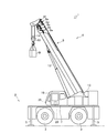
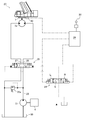
- the side view showing the whole crane composition concerning one embodiment of the present invention The figure which shows the hydraulic circuit for turning of the crane which concerns on one Embodiment of this invention.
- the figure which shows the flow volume characteristic after linearization. (A) The figure which shows the relationship (design value) of the opening degree of a spool, and a turning flow rate. (B) The figure which shows the relationship between the opening degree of a conventional spool, and a turning flow rate.
- FIGS. 1-9 the crane 1 provided with the control apparatus 39 which is one Embodiment of the turning control apparatus of this invention is demonstrated using FIGS. 1-9.
- a mobile crane will be described as a crane that is an example of a work machine.
- the present invention is not limited to this. The present invention can also be applied.
- the crane 1 is a mobile crane that can move to an unspecified location.
- the crane 1 has a vehicle 2 and a crane device 6.
- the vehicle 2 conveys the crane device 6.
- the vehicle 2 has a plurality of wheels 3 and travels using an engine 4 (see FIG. 2) as a power source.
- the vehicle 2 is provided with an outrigger 5.
- the outrigger 5 includes a projecting beam that can be extended by hydraulic pressure on both sides in the width direction of the vehicle 2 and a hydraulic jack cylinder that can extend in a direction perpendicular to the ground.
- the vehicle 2 can extend the workable range of the crane 1 by extending the beam of the outrigger 5 in the width direction of the vehicle 2 and grounding the jack cylinder.
- the crane apparatus 6 lifts the conveyed product W with a wire rope.
- the crane device 6 includes a swivel base 7, a telescopic boom 8, a hook block 10, a hoisting cylinder 12, a winch 13, a wire rope 14, a cabin 19, an operation lever 20, a control device 39 (see FIG. 4), and the like.
- the swivel base 7 is configured to allow the crane device 6 to turn.
- the swivel base 7 is provided on the frame of the vehicle 2 via a swivel bearing that is an annular bearing provided in the vehicle body 2.
- the ring-shaped slewing bearing is arranged so that the center of rotation is perpendicular to the installation surface of the vehicle 2.
- the swivel base 7 is configured to be rotatable in one direction and the other direction with the center of the annular swivel bearing as the center of rotation.
- the swivel base 7 is configured to be rotated (turned) by a swivel motor 7a (see FIG. 2) that is a hydraulic motor.
- the swivel base 7 is provided with a swivel position detection sensor 40 (see FIG. 2) for detecting the swivel position (turning angle).
- the turning position detection sensor 40 is a sensor that detects the turning angle of the turntable 7.
- information related to the turning angle of the turntable 7 based on the electrical signal input by the turning position detection sensor 40, And the information which concerns on turning speed (turning angular speed) is obtained by calculating the turning angle per unit time of the turntable 7.
- the slewing bearing of the slewing base 7 includes a slewing bearing load detecting means 43 (see FIG. 4) for detecting a load applied to the slewing bearing and a slewing bearing inclination angle detecting means 44 (see FIG. 4) for detecting an inclination angle of the slewing bearing with respect to the vehicle body 2. 4).
- the telescopic boom 8 supports the wire rope so that the transported object W can be lifted.
- the telescopic boom 8 includes a base boom member 8a, a second boom member 8b, a third boom member 8c, a force boom member 8d, a fifth boom member 8e, and a top boom member 8f, which are a plurality of boom members. Each boom member is inserted in a nested manner in the order of the cross-sectional area.
- the telescopic boom 8 is configured to be telescopic in the axial direction by moving each boom member with an unillustrated telescopic cylinder.
- the telescopic boom 8 is provided so that the base end of the base boom member 8 a can swing on the swivel base 7.
- the telescopic boom 8 is configured to be horizontally rotatable and swingable on the frame of the vehicle 2.
- the telescopic boom 8 is provided with an telescopic boom length detection sensor 41 for detecting the telescopic boom length and a hoisting angle detection sensor 42 (see FIG. 4) for detecting the hoisting angle.
- the hook block 10 is used to suspend the conveyed product W.
- the hook block 10 is provided with a plurality of hook sheaves around which the wire rope 14 is wound and a hook for hanging the conveyed product W.
- the raising / lowering cylinder 12 raises and lowers the telescopic boom 8 to hold the posture of the telescopic boom 8.
- the hoisting cylinder 12 is composed of a hydraulic cylinder composed of a cylinder part and a rod part.
- the end of the cylinder portion is swingably connected to the swivel base 7, and the end of the rod portion is swingably connected to the base boom member 8 a of the telescopic boom 8.
- the hoisting cylinder 12 elevates the base boom member 8a by supplying hydraulic oil so that the rod portion is pushed out of the cylinder portion, and the hydraulic oil is supplied so that the rod portion is pushed back to the cylinder portion.
- the boom member 8a is configured to fall down.
- the undulating cylinder 12 is provided with a pressure sensor 30 (see FIG. 4).
- the actual load of the suspended load is the cylinder pressure detected by the pressure sensor 30 of the hoisting cylinder 12, the hoisting angle detected by the hoisting angle detection sensor 42 of the telescopic boom 8, and the expansion / contraction detected by the telescopic boom length detection sensor 41.
- an actual load calculation unit (not shown) of the control device 39 can calculate and obtain it. Further, when the suspended load is not suspended and the load of the suspended load is known in advance, it may be input by a key operation of an operation unit (not shown) or a virtual load may be input.
- a winch 13 that is a hydraulic winch is for feeding (winding up) and feeding (winding down) the wire rope 14.
- the winch 13 is configured such that a drum around which the wire rope 14 is wound is rotated by a drum hydraulic motor.
- the winch 13 is supplied with hydraulic oil so that the drum hydraulic motor rotates in one direction, so that the wire rope 14 wound around the drum is fed, and the drum hydraulic motor rotates in the other direction. By supplying oil, the wire rope 14 is wound around a drum and fed.
- the telescoping cylinder used for the telescopic operation of the telescopic boom 8, the hoisting cylinder 12 used for the hoisting operation, and the turning motor 7a used for the turning operation of the swivel base 7 operate by supplying or discharging hydraulic oil.
- One end of the wire rope 14 is extended from the hook block 10, guided by a plurality of guide sheaves, and the other end is wound around a winch 13 disposed on the swivel base 7.
- the cabin 19 covers the cockpit.
- the cabin 19 is provided to the side of the telescopic boom 8 in the swivel base 7 and can swivel together with the swivel base 7.
- a cockpit is provided inside the cabin 19.
- the cockpit is provided with an operation lever 20, a winch operation valve for operating the winch 13, a hoisting operation tool for operating the telescopic boom 8, a handle for moving the crane 1, and the like.
- the operation lever 20 is an operation means for turning the turntable 7.
- the operation lever 20 is electrically connected to the control device 39, and the operator can transmit an operation signal for a turning operation corresponding to the operation lever 20 to the control device 39 by tilting the operation lever 20 by a predetermined angle.
- a push button, a pedal, a touch panel, or the like may be employed as the operation means.
- the crane 1 configured as described above can move the crane device 6 to an arbitrary position by running the vehicle 2. Further, the crane 1 rotates the swivel base 7 by a predetermined angle by the swing motor 7a, and erects the telescopic boom 8 to an arbitrary hoisting angle by the hoisting cylinder 12 to extend the telescopic boom 8 to an arbitrary telescopic boom length. Can be.
- the hydraulic circuit includes a hydraulic pump 21 to which driving force from the engine 4 is transmitted, a turning hydraulic circuit 23, and a control device 39.
- the hydraulic pump 21 discharges hydraulic oil.
- the hydraulic pump 21 is driven by the engine 4.
- the hydraulic oil discharged from the hydraulic pump 21 is supplied to the turning hydraulic circuit 23 and the turning motor 7a through the discharge oil passage 22.
- a relief valve 22 a is provided in the discharge oil passage 22 of the hydraulic pump 21.
- the turning hydraulic circuit 23 includes a meter-in throttle 23a that is a meter-in circuit, a meter-out throttle 23b that is a meter-out circuit, and a bleed-off throttle 23c that is a bleed-off circuit.
- the meter-in throttle 23a is disposed on the hydraulic oil supply side of the swing motor 7a and controls the flow rate of the hydraulic oil flowing into the swing motor 7a.
- the meter-out throttle 23b is disposed on the hydraulic oil discharge side of the swing motor 7a and controls the flow rate of the hydraulic oil flowing out of the swing motor 7a.
- the bleed-off throttle 23c controls the flow rate of the pressure oil that returns from the hydraulic pump 21 to the tank 50.
- the bleed-off throttle 23c can control the flow rate by adjusting the opening of a spool (not shown).
- the turning hydraulic circuit 23 operates the turning motor 7a.
- the turning hydraulic circuit 23 includes a turning motor 7 a, a turning operation valve 24, a turning pilot-type switching valve 25, and a turning position detection sensor 40.
- the turning motor 7a rotates the turntable 7.
- the turning motor 7 a is configured to be interlocked with the turning table 7. When the hydraulic oil is supplied, the turning motor 7a rotates in the one side direction or the other side direction of the turning table 7.
- the turning operation valve 24 controls the operation of the turning motor 7a.
- the turning operation valve 24 is composed of an electromagnetic switching valve that can switch the pilot pressure applied to the turning pilot type switching valve 25 by moving the spool with an electromagnet. Further, the turning operation valve 24 is configured to excite the electromagnet by a control signal from the control device 39. Pilot pressure is supplied from the hydraulic pump 21 to the turning operation valve 24. The turning operation valve 24 is controlled by an operation signal from the operation lever 20 via the control device 39.
- the spool When the operation valve 24 for turning is not receiving an operation signal from the control device 39, the spool is held at the stop position S. When the operation valve for turning 24 receives an operation signal for rotating the turntable 7 to one side from the control device 39, the spool is moved to the one-side turning position R by the electromagnet. When the turning operation valve 24 receives an operation signal for rotating the swivel base 7 from the control device 39 to the other side, the spool is moved to the other side turning position L by the electromagnet.
- the turning pilot type switching valve 25 switches the direction of the hydraulic oil supplied to the turning motor 7a.
- a hydraulic pump 21 is connected to a supply port of the turning pilot type switching valve 25 via a discharge oil passage 22.
- One side of the turning pilot type switching valve 25 is connected to one side of a turning motor 7 a via a one-side turning oil passage 26.
- the other port of the turning pilot type switching valve 25 is connected to the other side of the turning motor 7 a via the other-side turning oil passage 27.
- the turning pilot type switching valve 25 closes the one-side turning oil passage 26 and the other-side turning oil passage 27 when the spool of the turning operation valve 24 is held at the stop position S. Thereby, the rotation position of the turning motor 7a is maintained.
- the turning pilot-type switching valve 25 allows the hydraulic oil from the hydraulic pump 21 to move to the turning motor 7a via the one-side turning oil passage 26. Switch to supply to one side. Thereby, the turning motor 7a is operated in a direction in which the turntable 7 is rotated in one direction.
- the crane 1 having the turning hydraulic circuit 23 configured as described above switches the turning pilot type switching valve 25 by operating the turning operation valve 24 based on the operation signal from the control device 39. That is, the crane 1 can freely turn the swivel base 7 by switching the flow of hydraulic oil supplied to the turning motor 7 a according to an operation signal from the control device 39.
- the control device 39 is a device that controls the operation of an actuator or the like that the crane 1 has.
- the control device 39 is a turning control device for controlling a turning operation by the turning motor 7a which is one of actuators included in the crane 1 as an example of a control form.
- the control device 39 may actually be configured such that a CPU, ROM, RAM, HDD, or the like is connected by a bus, or may be configured by a one-chip LSI or the like.
- the control device 39 stores various programs and data for controlling the operation of the turning operation valve 24 and the like.
- the control device 39 is provided in the vehicle 2.
- the control device 39 receives various electrical signals from various sensors and can perform appropriate arithmetic processing, and can output drive signals to the hydraulic pump 21 and various flow control valves, respectively.
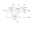
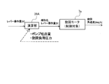
- the control device 39 includes a calculation unit 39A that executes various calculations using calculation formulas stored in advance in a storage unit, detection values acquired from various sensors, and the like. Further, the control device 39 is a control device for controlling the turning operation of the turntable 7 by general feedback control.
- the control device 39 is connected to the pressure sensor 30 of the hoisting cylinder 12.
- the actual load of the suspended load includes, for example, the cylinder pressure detected by the pressure sensor 30 of the hoisting cylinder 12, the hoisting angle detected by the hoisting angle detection sensor 42 of the telescopic boom 8, and the expansion and contraction.
- an actual load calculation unit (not shown) of the control device 39 can calculate and obtain it.
- the control device 39 is connected to the turning position detection sensor 40 of the turntable 7, and can acquire the turning direction and the turning angle of the turntable 7 detected by the turning position detection sensor 40.
- the control device 39 is connected to the telescopic boom length detection sensor 41 and the hoisting angle detection sensor 42 of the telescopic boom 8, and the telescopic boom length and hoisting angle detection sensor of the telescopic boom 8 detected by the telescopic boom length detection sensor 41.
- the undulation angle of the telescopic boom 8 detected by 42 can be acquired.
- the control device 39 is connected to the slewing bearing load detecting means 43 provided on the vehicle body 2 and can acquire the load applied to the slewing bearing.
- An example of the slewing bearing load detection means 43 includes a pressure sensor.
- the control device 39 is connected to the slewing bearing tilt angle detecting means 44 and can acquire the tilt angle of the slewing bearing provided on the vehicle body 2 with respect to the vehicle body 2.
- Control device 39 of the present embodiment estimates the turning load pressure [Delta] P A according to the time of turning operation of the turning base 7, and the discharge flow rate Q of the turning load pressure [Delta] P A and the hydraulic pump 21, and the opening area of the meter-circuit, the meter Based on the opening area of the out circuit and the opening area of the bleed-off circuit, the swirling flow rate Q A of the hydraulic oil flowing into the swiveling motor 7a during the swiveling operation of the swivel base 7 is estimated using a predetermined arithmetic expression, and the control lever 20 The relationship between the lever operation amount and the turning flow rate Q A is linearized. Details will be described below.
- the control device 39 controls the discharge flow rate Q of the hydraulic pump 21 and the discharge flow rate Q of the hydraulic pump 21 in order to suppress fluctuations in the turning angular velocity due to the pressure applied during the turning operation of the turntable 7 (swing load pressure). and in accordance with the turning load pressure [Delta] P a, linearization table (simply referred to as spool opening degree below) to alter the table showing the relationship (described later lever operation amount of the operation lever 20 and the bleed-off aperture 23c of valve opening Generation).
- the control device 39 loads the load applied to the slewing bearing provided on the vehicle body 2 as load information, the tilting angle of the slewing bearing and the crane working posture as posture information, the operation input information of the operator as operation information, and the rotation of the engine 4 as engine information.
- the number of information, other instrumental error due to the load variation such as turning load pressure ⁇ P information according to a of the other such constants (swing bearing specifications (coefficient of friction), the reduction ratio of the turning operation ( ⁇ total equivalent capacitance), the total efficiency ), or the like as appropriate get to the estimates the turning load pressure [Delta] P a based on this information.
- Turning load pressure [Delta] P A of estimating is a load which varies depending on the posture and the load of the crane.
- the turning load pressure [Delta] P A corresponds to a torque applied to the swing motor 7a at the start of turning operation of the swivel base 7.
- the control device 39 is connected to a slewing bearing load detection unit 43 that detects a load applied to the slewing bearing and a slewing bearing tilt angle detection unit 44 that detects an inclination angle of the slewing bearing with respect to the vehicle 2.
- the control device 39 can obtain the load applied to the slewing bearing and the tilt angle of the slewing bearing with respect to the vehicle 2 via the slewing bearing load detection unit 43 and the slewing bearing tilt angle detection unit 44.
- the control device 39 uses, for example, the pressure sensor 30, the turning position detection sensor 40, the telescopic boom length detection sensor 41, the undulation angle detection sensor 42, etc. as means for detecting the working posture of the crane 1. The working posture can be detected.
- the turning load pressure [Delta] P A is mainly determined by the moment applied to the swing bearing by suspended load load of the conveyed W. Therefore, the turning load pressure [Delta] P A is capable of estimating with a load applied to the swing bearing, which is acquired by at least swing bearing load detecting means 43.
- the turning flow rate Q A is a flow rate of hydraulic oil supplied to the turning motor 7a during the turning operation of the crane 1.
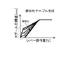
- the lever operation amount [V] and the turning flow rate Q A [L / min] Is a value calculated to derive a linearized flow characteristic (see FIG. 6) showing the relationship of An arithmetic expression for deriving the turning flow rate Q A is shown below.
- the meter opening area a in the aperture 23a, the opening area a out meter-out throttle 23b, and the bleed-off diaphragm 23c opening area a B in is uniquely determined by the spool opening (position of the spool).
- the control device 39 is connected to the hydraulic pump 21, the meter-in throttle 23a, the meter-out throttle 23b, and the bleed-off throttle 23c, and the discharge flow rate Q of the hydraulic pump 21, the opening area a in of the meter- in throttle 23a, and the opening area of the meter-out throttle 23b. a out and the opening area a B of the bleed-off stop 23c can be acquired.
- the opening degree of the spool for obtaining the turning flow rate Q A can be set uniquely, so that the inclination due to the change in the turning angular velocity due to the turning load pressure ⁇ P A It is possible to obtain a linearized table in which variations are unified and linearized (see FIG. 5). That is, as shown in FIG. 10, the spool opening target value (spool target position P) corresponding to the lever operation amount, which is the design value of the turning flow rate Q A , from the relationship between the design value and the curve obtained from the above arithmetic expression. Can be calculated.
- the dotted line circle mark part shown in FIG. 5 is a dead zone skip part provided intentionally.
- the linearization table shown in FIG. 5 uniquely determines the turning flow rate Q A and the lever operation amount of the operation lever 20, and shows the relationship between the lever operation amount [V] and the turning flow rate Q A [L / min].
- the flow characteristics after conversion can be obtained.
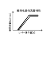
- the flow characteristics according to the present embodiment maintain a linear relationship as compared with the conventional flow characteristics shown in FIG.
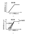
- the design value indicating the relationship between the spool opening (spool position) [mm] and the turning flow rate Q A [L / min] is a linear relationship at the start of the turning operation. And its inclination is constant.
- the crane 1 is operated to simulate various conditions and the relationship between the conventional spool opening (spool position) [mm] and the turning flow rate Q A [L / min] is estimated The result is as shown in FIG. Variations in the spool opening occur with respect to the turning flow rate Q A , and the inclination varies.
- Variation of the inclination is to pivot the load pressure [Delta] P A occurs to change.
- Q p of FIG. 7 (b) shows the variation in the delivery rate of the hydraulic pump 21.
- the maximum value of the turning flow rate Q A (max in FIG. 7B) varies according to the discharge flow rate of the hydraulic pump 21, and the operator 4 intentionally changes the maximum value of the turning flow rate Q A. It is a part resulting from controlling the rotation speed of this, and is not a part corresponding to the subject of this invention.
- the estimated value of the turning load pressure ⁇ P A is calculated in advance, the turning flow rate Q A is estimated from this and the above equation, and the spool for obtaining this turning flow rate Q A is obtained.
- the target value (target position) [mm] of the opening is determined.
- the lever operation amount of the operation lever 20 is uniquely determined from the target value of the opening degree of the spool (see FIG. 5), and based on this, the linearized flow rate characteristic shown in FIG. 6 can be obtained.
- the relationship between the lever operation amount [V] of the operation lever 20 and the turning flow rate Q A [L / min] can be kept linear (constant) at the time of starting the turning operation.
- the control target of the control device 39 which is an example of the swing control device, is not limited to a specific control target, and includes a swing operation unit included in other work machines, mobile vehicles, production machines, and the like that perform the swing operation. .
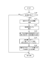
- step S100 the control device 39 determines whether or not the operation lever 20 is operated and the turning operation by the turning motor 7a of the crane 1 is started. That is, the control device 39 determines whether or not an operation signal indicating that the operator has operated the operation lever 20 is input to the calculation unit 39A. As a result, when it is determined that the operation lever 20 is operated and the turning operation by the turning motor 7a is started, the control device 39 shifts the step to step S110. On the other hand, when it is determined that the operation lever 20 is not operated and the turning operation by the turning motor 7a is not performed, the control device 39 shifts the step to step S100.
- step S110 the control device 39 acquires the discharge flow rate Q of the hydraulic pump 21, and shifts the step to step S120.
- step S120 the control unit 39 estimates the turning load pressure [Delta] P A, as described above, it shifts the step to step S130.
- step S130 the control unit 39, the discharge flow rate Q as the above-described arithmetic expression and the turning load pressure [Delta] P A estimated in step S120, the meter diaphragm opening area a in the hydraulic pump 21 acquired in step S110 in the operation section 39A,
- the turning flow rate Q A is estimated by performing calculation processing in the calculation unit 39A using the opening area a out of the meter-out aperture and the opening area a B of the bleed-off aperture, and the process proceeds to step S140.
- step S140 the controller 39 calculates a target value of the spool opening for obtaining a turning flow Q A, linearization table linearizing the relationship between the target value and the lever operation amount of opening of the spool Create Subsequently, the control device 39 shifts the step to step S150.
- step S150 the control unit 39, based on the flow characteristics showing the relationship between the lever operation amount determined based on the linearization table created swirling flow Q A in step S140, the lever operation amount of the operator of the operation lever 20 The turning flow rate Q A corresponding to is uniquely determined. Then, in response to the lever operation amount [V] of the linearized operation lever 20, hydraulic oil is supplied to the turning motor 7a to be controlled, and the turntable 7 is moved to a desired turning angular velocity [deg / s] can be turned (see FIG. 9).
- the control device 39 changes the linearization table that linearizes the relationship between the lever operation amount of the operation lever 20 and the spool target value, lever operation amount of the lever 20 and the relationship of the turning rate Q a is prevented from fluctuation.
- the control device 39 linearizes the relationship between the lever operation amount of the operation lever 20 and the corresponding turning flow rate Q A without changing the valve of the existing hydraulic circuit, and turns.
- the operation can be controlled.
- the turning operation due to changes in discharge flow rate Q and the turning load pressure [Delta] P A of the hydraulic pump 21 e.g., turning angular velocity
- the feedback controllability of the turning operation is improved.
- the present invention can be used as a turning control device that improves the turning operability of a work machine such as a crane.
Landscapes
- Engineering & Computer Science (AREA)
- Mechanical Engineering (AREA)
- Physics & Mathematics (AREA)
- Fluid Mechanics (AREA)
- General Engineering & Computer Science (AREA)
- Fluid-Pressure Circuits (AREA)
- Jib Cranes (AREA)
Applications Claiming Priority (2)
| Application Number | Priority Date | Filing Date | Title |
|---|---|---|---|
| JP2017-013711 | 2017-01-27 | ||
| JP2017013711A JP6540724B2 (ja) | 2017-01-27 | 2017-01-27 | 旋回制御装置 |
Publications (1)
| Publication Number | Publication Date |
|---|---|
| WO2018139166A1 true WO2018139166A1 (ja) | 2018-08-02 |
Family
ID=62978310
Family Applications (1)
| Application Number | Title | Priority Date | Filing Date |
|---|---|---|---|
| PCT/JP2017/047294 Ceased WO2018139166A1 (ja) | 2017-01-27 | 2017-12-28 | 旋回制御装置 |
Country Status (2)
| Country | Link |
|---|---|
| JP (1) | JP6540724B2 (enExample) |
| WO (1) | WO2018139166A1 (enExample) |
Families Citing this family (1)
| Publication number | Priority date | Publication date | Assignee | Title |
|---|---|---|---|---|
| JP7184672B2 (ja) * | 2019-02-27 | 2022-12-06 | 株式会社タダノ | 作業車両 |
Citations (6)
| Publication number | Priority date | Publication date | Assignee | Title |
|---|---|---|---|---|
| JPH0610905A (ja) * | 1992-06-24 | 1994-01-21 | Komatsu Ltd | 操作弁の開度制御方法 |
| JPH10159809A (ja) * | 1996-11-28 | 1998-06-16 | Kobe Steel Ltd | 油圧アクチュエータの流量制御装置 |
| JPH1136376A (ja) * | 1997-07-17 | 1999-02-09 | Komatsu Ltd | 作業機における旋回起動制御装置 |
| JPH1171097A (ja) * | 1997-09-01 | 1999-03-16 | Hitachi Constr Mach Co Ltd | 作業機の旋回制御装置 |
| JP2000009102A (ja) * | 1998-06-22 | 2000-01-11 | Kobe Steel Ltd | 油圧アクチュエータの制御装置 |
| JP2015067993A (ja) * | 2013-09-27 | 2015-04-13 | ダイキン工業株式会社 | 建設機械 |
Family Cites Families (2)
| Publication number | Priority date | Publication date | Assignee | Title |
|---|---|---|---|---|
| JPH0258062U (enExample) * | 1988-10-17 | 1990-04-26 | ||
| JP4997138B2 (ja) * | 2008-02-20 | 2012-08-08 | 日立建機株式会社 | 荷重負荷機械 |
-
2017
- 2017-01-27 JP JP2017013711A patent/JP6540724B2/ja active Active
- 2017-12-28 WO PCT/JP2017/047294 patent/WO2018139166A1/ja not_active Ceased
Patent Citations (6)
| Publication number | Priority date | Publication date | Assignee | Title |
|---|---|---|---|---|
| JPH0610905A (ja) * | 1992-06-24 | 1994-01-21 | Komatsu Ltd | 操作弁の開度制御方法 |
| JPH10159809A (ja) * | 1996-11-28 | 1998-06-16 | Kobe Steel Ltd | 油圧アクチュエータの流量制御装置 |
| JPH1136376A (ja) * | 1997-07-17 | 1999-02-09 | Komatsu Ltd | 作業機における旋回起動制御装置 |
| JPH1171097A (ja) * | 1997-09-01 | 1999-03-16 | Hitachi Constr Mach Co Ltd | 作業機の旋回制御装置 |
| JP2000009102A (ja) * | 1998-06-22 | 2000-01-11 | Kobe Steel Ltd | 油圧アクチュエータの制御装置 |
| JP2015067993A (ja) * | 2013-09-27 | 2015-04-13 | ダイキン工業株式会社 | 建設機械 |
Also Published As
| Publication number | Publication date |
|---|---|
| JP6540724B2 (ja) | 2019-07-10 |
| JP2018119667A (ja) | 2018-08-02 |
Similar Documents
| Publication | Publication Date | Title |
|---|---|---|
| CN108603360B (zh) | 挖土机 | |
| JPWO2017115809A1 (ja) | ショベル | |
| US20170184139A1 (en) | Method of controlling velocity of a hydraulic actuator in over-center linkage systems | |
| WO2009104449A1 (ja) | 作業機械における干渉防止制御装置 | |
| JP2010230039A (ja) | 流体圧回路 | |
| JP2013543086A (ja) | 建設機械用可変容量型油圧ポンプの流量制御装置 | |
| JP6915042B2 (ja) | ショベル | |
| JP6803194B2 (ja) | 建設機械の油圧駆動システム | |
| JP5970625B1 (ja) | 建設機械、ハイブリッド油圧ショベル、および電動発電機の出力トルク制御方法 | |
| US7546729B2 (en) | Method and system for limiting torque load associated with an implement | |
| CN109689982B (zh) | 工程机械 | |
| CN108883915B (zh) | 起重机 | |
| WO2016121185A1 (ja) | 旋回制御装置 | |
| WO2018139166A1 (ja) | 旋回制御装置 | |
| CN113454346B (zh) | 作业车辆 | |
| WO2022210776A1 (ja) | ショベル | |
| JP2001199676A (ja) | 建設機械の操作系油圧回路 | |
| JP2001302183A (ja) | 油圧速度制御装置、フック過巻防止装置および干渉防止装置 | |
| JP5639855B2 (ja) | 油圧駆動装置および油圧駆動装置を備えた作業機械 | |
| JP2024136810A (ja) | 作業機械の制御装置および作業機械、作業機械の制御方法 | |
| JP6943798B2 (ja) | ショベル | |
| JP6445352B2 (ja) | 作業機械 | |
| CN111492111B (zh) | 挖土机 | |
| JP4490654B2 (ja) | 作業機のアクセル制御装置 | |
| CN102700413B (zh) | 工程机械的发动机控制装置 |
Legal Events
| Date | Code | Title | Description |
|---|---|---|---|
| 121 | Ep: the epo has been informed by wipo that ep was designated in this application |
Ref document number: 17894059 Country of ref document: EP Kind code of ref document: A1 |
|
| NENP | Non-entry into the national phase |
Ref country code: DE |
|
| 122 | Ep: pct application non-entry in european phase |
Ref document number: 17894059 Country of ref document: EP Kind code of ref document: A1 |