WO2018139166A1 - Revolution control device - Google Patents
Revolution control device Download PDFInfo
- Publication number
- WO2018139166A1 WO2018139166A1 PCT/JP2017/047294 JP2017047294W WO2018139166A1 WO 2018139166 A1 WO2018139166 A1 WO 2018139166A1 JP 2017047294 W JP2017047294 W JP 2017047294W WO 2018139166 A1 WO2018139166 A1 WO 2018139166A1
- Authority
- WO
- WIPO (PCT)
- Prior art keywords
- turning
- flow rate
- revolving
- circuit
- control device
- Prior art date
Links
Images


Classifications
-
- B—PERFORMING OPERATIONS; TRANSPORTING
- B66—HOISTING; LIFTING; HAULING
- B66C—CRANES; LOAD-ENGAGING ELEMENTS OR DEVICES FOR CRANES, CAPSTANS, WINCHES, OR TACKLES
- B66C23/00—Cranes comprising essentially a beam, boom, or triangular structure acting as a cantilever and mounted for translatory of swinging movements in vertical or horizontal planes or a combination of such movements, e.g. jib-cranes, derricks, tower cranes
- B66C23/62—Constructional features or details
- B66C23/84—Slewing gear
- B66C23/86—Slewing gear hydraulically actuated
-
- F—MECHANICAL ENGINEERING; LIGHTING; HEATING; WEAPONS; BLASTING
- F15—FLUID-PRESSURE ACTUATORS; HYDRAULICS OR PNEUMATICS IN GENERAL
- F15B—SYSTEMS ACTING BY MEANS OF FLUIDS IN GENERAL; FLUID-PRESSURE ACTUATORS, e.g. SERVOMOTORS; DETAILS OF FLUID-PRESSURE SYSTEMS, NOT OTHERWISE PROVIDED FOR
- F15B11/00—Servomotor systems without provision for follow-up action; Circuits therefor
- F15B11/02—Systems essentially incorporating special features for controlling the speed or actuating force of an output member
- F15B11/04—Systems essentially incorporating special features for controlling the speed or actuating force of an output member for controlling the speed
- F15B11/042—Systems essentially incorporating special features for controlling the speed or actuating force of an output member for controlling the speed by means in the feed line, i.e. "meter in"
-
- F—MECHANICAL ENGINEERING; LIGHTING; HEATING; WEAPONS; BLASTING
- F15—FLUID-PRESSURE ACTUATORS; HYDRAULICS OR PNEUMATICS IN GENERAL
- F15B—SYSTEMS ACTING BY MEANS OF FLUIDS IN GENERAL; FLUID-PRESSURE ACTUATORS, e.g. SERVOMOTORS; DETAILS OF FLUID-PRESSURE SYSTEMS, NOT OTHERWISE PROVIDED FOR
- F15B11/00—Servomotor systems without provision for follow-up action; Circuits therefor
- F15B11/02—Systems essentially incorporating special features for controlling the speed or actuating force of an output member
- F15B11/04—Systems essentially incorporating special features for controlling the speed or actuating force of an output member for controlling the speed
- F15B11/044—Systems essentially incorporating special features for controlling the speed or actuating force of an output member for controlling the speed by means in the return line, i.e. "meter out"
Definitions
- the present invention relates to a turning control device. Specifically, the present invention relates to a turning control device that improves the turning operability of a work machine such as a crane.
- Patent Document 1 discloses a swing control device for a working machine that controls the rotational speed of a hydraulic motor by bleed-off control of pressure oil from a variable displacement hydraulic pump with a directional control valve.
- This swing control device for a work machine sets the pressure of a bleed-off circuit communicating from the direction control valve to the tank equal to the drive pressure of the hydraulic motor, and is a direction control valve previously associated with the working state of the work machine.
- One of the plurality of flow rate characteristics is selected based on the working state, and the discharge flow rate of the variable displacement hydraulic pump is controlled based on the selected flow rate characteristic and the operation amount.
- the bleed-off control device for an actuator disclosed in Patent Document 2 keeps the operating speed constant by opening and closing the bleed-off circuit according to the pump discharge amount.
- the lever of the operation lever for the turning operation depends on fluctuations in the discharge flow rate of the hydraulic pump and the load applied to the actuator during turning (for example, the load due to the suspended load).
- the turning speed varies with the operation amount. That is, even if the same turning operation is performed, the movement changes depending on the turning load applied at that time.
- Such characteristics of the turning operation have a problem that, for example, the controllability is deteriorated when feedback control is performed on the turning operation, and the operation quality and the operation feeling are deteriorated depending on the operation conditions. Therefore, there is a demand for a technique that suppresses the fluctuation of the turning speed with respect to the lever operation amount and stabilizes the turning speed regardless of conditions. That is, there is a need for a technique for realizing the turning operability such that the turning speed with respect to the turning operation by the operation lever is constant regardless of the discharge flow rate and the turning load of the hydraulic pump.
- An object of the present invention is to provide a turning control device that realizes a turning operability with a small variation in operation feeling irrespective of the discharge flow rate and turning load of a hydraulic pump.
- the turning control device of the present invention includes a turning base, operating means for turning the turning base, a hydraulic motor for turning the turn base, and a hydraulic pump for supplying hydraulic oil to the hydraulic motor.
- a meter-in circuit for controlling the flow rate of hydraulic oil flowing into the hydraulic motor a meter-out circuit for controlling the flow rate of hydraulic oil flowing out of the hydraulic motor, and a flow rate of pressure oil returning from the hydraulic pump to the tank
- a bleed-off circuit for controlling a turning operation of a work machine, wherein the turning load pressure applied during the turning operation of the swivel base is estimated, and the turning load pressure and the discharge flow rate of the hydraulic pump
- the opening area of the meter-in circuit, the opening area of the meter-out circuit, and the opening area of the bleed-off circuit is to linearize the relationship between the operation amount and the turning flow of the operating means.
- the predetermined arithmetic expression is (Where, Q: discharge flow rate of hydraulic pump, ⁇ P A : swing load pressure, a in : opening area of meter-in circuit, a out : opening area of meter-out circuit, a B : opening area of bleed-off circuit, R: Coefficient).
- the present invention has the following effects.
- the turning control device of the present invention it is possible to control the turning operation by linearizing the relationship between the operation amount of the operating means and the corresponding turning flow rate without changing the valve or the like of the existing hydraulic circuit.
- movement for example, turning angular velocity
- movement for example, turning angular velocity
- movement for example, turning angular velocity
- movement for example, turning angular velocity
- movement for example, turning angular velocity
- movement by the change of the discharge flow rate of a hydraulic pump or turning load pressure
- the feedback controllability is improved.
- the side view showing the whole crane composition concerning one embodiment of the present invention The figure which shows the hydraulic circuit for turning of the crane which concerns on one Embodiment of this invention.
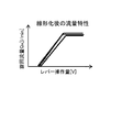
- the figure which shows the flow volume characteristic after linearization. (A) The figure which shows the relationship (design value) of the opening degree of a spool, and a turning flow rate. (B) The figure which shows the relationship between the opening degree of a conventional spool, and a turning flow rate.
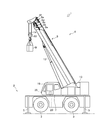
- FIGS. 1-9 the crane 1 provided with the control apparatus 39 which is one Embodiment of the turning control apparatus of this invention is demonstrated using FIGS. 1-9.
- a mobile crane will be described as a crane that is an example of a work machine.
- the present invention is not limited to this. The present invention can also be applied.
- the crane 1 is a mobile crane that can move to an unspecified location.
- the crane 1 has a vehicle 2 and a crane device 6.
- the vehicle 2 conveys the crane device 6.
- the vehicle 2 has a plurality of wheels 3 and travels using an engine 4 (see FIG. 2) as a power source.
- the vehicle 2 is provided with an outrigger 5.
- the outrigger 5 includes a projecting beam that can be extended by hydraulic pressure on both sides in the width direction of the vehicle 2 and a hydraulic jack cylinder that can extend in a direction perpendicular to the ground.
- the vehicle 2 can extend the workable range of the crane 1 by extending the beam of the outrigger 5 in the width direction of the vehicle 2 and grounding the jack cylinder.
- the crane apparatus 6 lifts the conveyed product W with a wire rope.
- the crane device 6 includes a swivel base 7, a telescopic boom 8, a hook block 10, a hoisting cylinder 12, a winch 13, a wire rope 14, a cabin 19, an operation lever 20, a control device 39 (see FIG. 4), and the like.
- the swivel base 7 is configured to allow the crane device 6 to turn.
- the swivel base 7 is provided on the frame of the vehicle 2 via a swivel bearing that is an annular bearing provided in the vehicle body 2.
- the ring-shaped slewing bearing is arranged so that the center of rotation is perpendicular to the installation surface of the vehicle 2.
- the swivel base 7 is configured to be rotatable in one direction and the other direction with the center of the annular swivel bearing as the center of rotation.
- the swivel base 7 is configured to be rotated (turned) by a swivel motor 7a (see FIG. 2) that is a hydraulic motor.
- the swivel base 7 is provided with a swivel position detection sensor 40 (see FIG. 2) for detecting the swivel position (turning angle).
- the turning position detection sensor 40 is a sensor that detects the turning angle of the turntable 7.
- information related to the turning angle of the turntable 7 based on the electrical signal input by the turning position detection sensor 40, And the information which concerns on turning speed (turning angular speed) is obtained by calculating the turning angle per unit time of the turntable 7.
- the slewing bearing of the slewing base 7 includes a slewing bearing load detecting means 43 (see FIG. 4) for detecting a load applied to the slewing bearing and a slewing bearing inclination angle detecting means 44 (see FIG. 4) for detecting an inclination angle of the slewing bearing with respect to the vehicle body 2. 4).
- the telescopic boom 8 supports the wire rope so that the transported object W can be lifted.
- the telescopic boom 8 includes a base boom member 8a, a second boom member 8b, a third boom member 8c, a force boom member 8d, a fifth boom member 8e, and a top boom member 8f, which are a plurality of boom members. Each boom member is inserted in a nested manner in the order of the cross-sectional area.
- the telescopic boom 8 is configured to be telescopic in the axial direction by moving each boom member with an unillustrated telescopic cylinder.
- the telescopic boom 8 is provided so that the base end of the base boom member 8 a can swing on the swivel base 7.
- the telescopic boom 8 is configured to be horizontally rotatable and swingable on the frame of the vehicle 2.
- the telescopic boom 8 is provided with an telescopic boom length detection sensor 41 for detecting the telescopic boom length and a hoisting angle detection sensor 42 (see FIG. 4) for detecting the hoisting angle.
- the hook block 10 is used to suspend the conveyed product W.
- the hook block 10 is provided with a plurality of hook sheaves around which the wire rope 14 is wound and a hook for hanging the conveyed product W.
- the raising / lowering cylinder 12 raises and lowers the telescopic boom 8 to hold the posture of the telescopic boom 8.
- the hoisting cylinder 12 is composed of a hydraulic cylinder composed of a cylinder part and a rod part.
- the end of the cylinder portion is swingably connected to the swivel base 7, and the end of the rod portion is swingably connected to the base boom member 8 a of the telescopic boom 8.
- the hoisting cylinder 12 elevates the base boom member 8a by supplying hydraulic oil so that the rod portion is pushed out of the cylinder portion, and the hydraulic oil is supplied so that the rod portion is pushed back to the cylinder portion.
- the boom member 8a is configured to fall down.
- the undulating cylinder 12 is provided with a pressure sensor 30 (see FIG. 4).
- the actual load of the suspended load is the cylinder pressure detected by the pressure sensor 30 of the hoisting cylinder 12, the hoisting angle detected by the hoisting angle detection sensor 42 of the telescopic boom 8, and the expansion / contraction detected by the telescopic boom length detection sensor 41.
- an actual load calculation unit (not shown) of the control device 39 can calculate and obtain it. Further, when the suspended load is not suspended and the load of the suspended load is known in advance, it may be input by a key operation of an operation unit (not shown) or a virtual load may be input.
- a winch 13 that is a hydraulic winch is for feeding (winding up) and feeding (winding down) the wire rope 14.
- the winch 13 is configured such that a drum around which the wire rope 14 is wound is rotated by a drum hydraulic motor.
- the winch 13 is supplied with hydraulic oil so that the drum hydraulic motor rotates in one direction, so that the wire rope 14 wound around the drum is fed, and the drum hydraulic motor rotates in the other direction. By supplying oil, the wire rope 14 is wound around a drum and fed.
- the telescoping cylinder used for the telescopic operation of the telescopic boom 8, the hoisting cylinder 12 used for the hoisting operation, and the turning motor 7a used for the turning operation of the swivel base 7 operate by supplying or discharging hydraulic oil.
- One end of the wire rope 14 is extended from the hook block 10, guided by a plurality of guide sheaves, and the other end is wound around a winch 13 disposed on the swivel base 7.
- the cabin 19 covers the cockpit.
- the cabin 19 is provided to the side of the telescopic boom 8 in the swivel base 7 and can swivel together with the swivel base 7.
- a cockpit is provided inside the cabin 19.
- the cockpit is provided with an operation lever 20, a winch operation valve for operating the winch 13, a hoisting operation tool for operating the telescopic boom 8, a handle for moving the crane 1, and the like.
- the operation lever 20 is an operation means for turning the turntable 7.
- the operation lever 20 is electrically connected to the control device 39, and the operator can transmit an operation signal for a turning operation corresponding to the operation lever 20 to the control device 39 by tilting the operation lever 20 by a predetermined angle.
- a push button, a pedal, a touch panel, or the like may be employed as the operation means.
- the crane 1 configured as described above can move the crane device 6 to an arbitrary position by running the vehicle 2. Further, the crane 1 rotates the swivel base 7 by a predetermined angle by the swing motor 7a, and erects the telescopic boom 8 to an arbitrary hoisting angle by the hoisting cylinder 12 to extend the telescopic boom 8 to an arbitrary telescopic boom length. Can be.
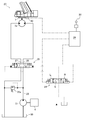
- the hydraulic circuit includes a hydraulic pump 21 to which driving force from the engine 4 is transmitted, a turning hydraulic circuit 23, and a control device 39.
- the hydraulic pump 21 discharges hydraulic oil.
- the hydraulic pump 21 is driven by the engine 4.
- the hydraulic oil discharged from the hydraulic pump 21 is supplied to the turning hydraulic circuit 23 and the turning motor 7a through the discharge oil passage 22.
- a relief valve 22 a is provided in the discharge oil passage 22 of the hydraulic pump 21.
- the turning hydraulic circuit 23 includes a meter-in throttle 23a that is a meter-in circuit, a meter-out throttle 23b that is a meter-out circuit, and a bleed-off throttle 23c that is a bleed-off circuit.
- the meter-in throttle 23a is disposed on the hydraulic oil supply side of the swing motor 7a and controls the flow rate of the hydraulic oil flowing into the swing motor 7a.
- the meter-out throttle 23b is disposed on the hydraulic oil discharge side of the swing motor 7a and controls the flow rate of the hydraulic oil flowing out of the swing motor 7a.
- the bleed-off throttle 23c controls the flow rate of the pressure oil that returns from the hydraulic pump 21 to the tank 50.
- the bleed-off throttle 23c can control the flow rate by adjusting the opening of a spool (not shown).
- the turning hydraulic circuit 23 operates the turning motor 7a.
- the turning hydraulic circuit 23 includes a turning motor 7 a, a turning operation valve 24, a turning pilot-type switching valve 25, and a turning position detection sensor 40.
- the turning motor 7a rotates the turntable 7.
- the turning motor 7 a is configured to be interlocked with the turning table 7. When the hydraulic oil is supplied, the turning motor 7a rotates in the one side direction or the other side direction of the turning table 7.
- the turning operation valve 24 controls the operation of the turning motor 7a.
- the turning operation valve 24 is composed of an electromagnetic switching valve that can switch the pilot pressure applied to the turning pilot type switching valve 25 by moving the spool with an electromagnet. Further, the turning operation valve 24 is configured to excite the electromagnet by a control signal from the control device 39. Pilot pressure is supplied from the hydraulic pump 21 to the turning operation valve 24. The turning operation valve 24 is controlled by an operation signal from the operation lever 20 via the control device 39.
- the spool When the operation valve 24 for turning is not receiving an operation signal from the control device 39, the spool is held at the stop position S. When the operation valve for turning 24 receives an operation signal for rotating the turntable 7 to one side from the control device 39, the spool is moved to the one-side turning position R by the electromagnet. When the turning operation valve 24 receives an operation signal for rotating the swivel base 7 from the control device 39 to the other side, the spool is moved to the other side turning position L by the electromagnet.
- the turning pilot type switching valve 25 switches the direction of the hydraulic oil supplied to the turning motor 7a.
- a hydraulic pump 21 is connected to a supply port of the turning pilot type switching valve 25 via a discharge oil passage 22.
- One side of the turning pilot type switching valve 25 is connected to one side of a turning motor 7 a via a one-side turning oil passage 26.
- the other port of the turning pilot type switching valve 25 is connected to the other side of the turning motor 7 a via the other-side turning oil passage 27.
- the turning pilot type switching valve 25 closes the one-side turning oil passage 26 and the other-side turning oil passage 27 when the spool of the turning operation valve 24 is held at the stop position S. Thereby, the rotation position of the turning motor 7a is maintained.
- the turning pilot-type switching valve 25 allows the hydraulic oil from the hydraulic pump 21 to move to the turning motor 7a via the one-side turning oil passage 26. Switch to supply to one side. Thereby, the turning motor 7a is operated in a direction in which the turntable 7 is rotated in one direction.
- the crane 1 having the turning hydraulic circuit 23 configured as described above switches the turning pilot type switching valve 25 by operating the turning operation valve 24 based on the operation signal from the control device 39. That is, the crane 1 can freely turn the swivel base 7 by switching the flow of hydraulic oil supplied to the turning motor 7 a according to an operation signal from the control device 39.
- the control device 39 is a device that controls the operation of an actuator or the like that the crane 1 has.
- the control device 39 is a turning control device for controlling a turning operation by the turning motor 7a which is one of actuators included in the crane 1 as an example of a control form.
- the control device 39 may actually be configured such that a CPU, ROM, RAM, HDD, or the like is connected by a bus, or may be configured by a one-chip LSI or the like.
- the control device 39 stores various programs and data for controlling the operation of the turning operation valve 24 and the like.
- the control device 39 is provided in the vehicle 2.
- the control device 39 receives various electrical signals from various sensors and can perform appropriate arithmetic processing, and can output drive signals to the hydraulic pump 21 and various flow control valves, respectively.
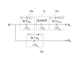
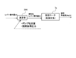
- the control device 39 includes a calculation unit 39A that executes various calculations using calculation formulas stored in advance in a storage unit, detection values acquired from various sensors, and the like. Further, the control device 39 is a control device for controlling the turning operation of the turntable 7 by general feedback control.
- the control device 39 is connected to the pressure sensor 30 of the hoisting cylinder 12.
- the actual load of the suspended load includes, for example, the cylinder pressure detected by the pressure sensor 30 of the hoisting cylinder 12, the hoisting angle detected by the hoisting angle detection sensor 42 of the telescopic boom 8, and the expansion and contraction.
- an actual load calculation unit (not shown) of the control device 39 can calculate and obtain it.
- the control device 39 is connected to the turning position detection sensor 40 of the turntable 7, and can acquire the turning direction and the turning angle of the turntable 7 detected by the turning position detection sensor 40.
- the control device 39 is connected to the telescopic boom length detection sensor 41 and the hoisting angle detection sensor 42 of the telescopic boom 8, and the telescopic boom length and hoisting angle detection sensor of the telescopic boom 8 detected by the telescopic boom length detection sensor 41.
- the undulation angle of the telescopic boom 8 detected by 42 can be acquired.
- the control device 39 is connected to the slewing bearing load detecting means 43 provided on the vehicle body 2 and can acquire the load applied to the slewing bearing.
- An example of the slewing bearing load detection means 43 includes a pressure sensor.
- the control device 39 is connected to the slewing bearing tilt angle detecting means 44 and can acquire the tilt angle of the slewing bearing provided on the vehicle body 2 with respect to the vehicle body 2.
- Control device 39 of the present embodiment estimates the turning load pressure [Delta] P A according to the time of turning operation of the turning base 7, and the discharge flow rate Q of the turning load pressure [Delta] P A and the hydraulic pump 21, and the opening area of the meter-circuit, the meter Based on the opening area of the out circuit and the opening area of the bleed-off circuit, the swirling flow rate Q A of the hydraulic oil flowing into the swiveling motor 7a during the swiveling operation of the swivel base 7 is estimated using a predetermined arithmetic expression, and the control lever 20 The relationship between the lever operation amount and the turning flow rate Q A is linearized. Details will be described below.
- the control device 39 controls the discharge flow rate Q of the hydraulic pump 21 and the discharge flow rate Q of the hydraulic pump 21 in order to suppress fluctuations in the turning angular velocity due to the pressure applied during the turning operation of the turntable 7 (swing load pressure). and in accordance with the turning load pressure [Delta] P a, linearization table (simply referred to as spool opening degree below) to alter the table showing the relationship (described later lever operation amount of the operation lever 20 and the bleed-off aperture 23c of valve opening Generation).
- the control device 39 loads the load applied to the slewing bearing provided on the vehicle body 2 as load information, the tilting angle of the slewing bearing and the crane working posture as posture information, the operation input information of the operator as operation information, and the rotation of the engine 4 as engine information.
- the number of information, other instrumental error due to the load variation such as turning load pressure ⁇ P information according to a of the other such constants (swing bearing specifications (coefficient of friction), the reduction ratio of the turning operation ( ⁇ total equivalent capacitance), the total efficiency ), or the like as appropriate get to the estimates the turning load pressure [Delta] P a based on this information.
- Turning load pressure [Delta] P A of estimating is a load which varies depending on the posture and the load of the crane.
- the turning load pressure [Delta] P A corresponds to a torque applied to the swing motor 7a at the start of turning operation of the swivel base 7.
- the control device 39 is connected to a slewing bearing load detection unit 43 that detects a load applied to the slewing bearing and a slewing bearing tilt angle detection unit 44 that detects an inclination angle of the slewing bearing with respect to the vehicle 2.
- the control device 39 can obtain the load applied to the slewing bearing and the tilt angle of the slewing bearing with respect to the vehicle 2 via the slewing bearing load detection unit 43 and the slewing bearing tilt angle detection unit 44.
- the control device 39 uses, for example, the pressure sensor 30, the turning position detection sensor 40, the telescopic boom length detection sensor 41, the undulation angle detection sensor 42, etc. as means for detecting the working posture of the crane 1. The working posture can be detected.
- the turning load pressure [Delta] P A is mainly determined by the moment applied to the swing bearing by suspended load load of the conveyed W. Therefore, the turning load pressure [Delta] P A is capable of estimating with a load applied to the swing bearing, which is acquired by at least swing bearing load detecting means 43.
- the turning flow rate Q A is a flow rate of hydraulic oil supplied to the turning motor 7a during the turning operation of the crane 1.
- the lever operation amount [V] and the turning flow rate Q A [L / min] Is a value calculated to derive a linearized flow characteristic (see FIG. 6) showing the relationship of An arithmetic expression for deriving the turning flow rate Q A is shown below.
- the meter opening area a in the aperture 23a, the opening area a out meter-out throttle 23b, and the bleed-off diaphragm 23c opening area a B in is uniquely determined by the spool opening (position of the spool).
- the control device 39 is connected to the hydraulic pump 21, the meter-in throttle 23a, the meter-out throttle 23b, and the bleed-off throttle 23c, and the discharge flow rate Q of the hydraulic pump 21, the opening area a in of the meter- in throttle 23a, and the opening area of the meter-out throttle 23b. a out and the opening area a B of the bleed-off stop 23c can be acquired.
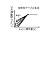
- the opening degree of the spool for obtaining the turning flow rate Q A can be set uniquely, so that the inclination due to the change in the turning angular velocity due to the turning load pressure ⁇ P A It is possible to obtain a linearized table in which variations are unified and linearized (see FIG. 5). That is, as shown in FIG. 10, the spool opening target value (spool target position P) corresponding to the lever operation amount, which is the design value of the turning flow rate Q A , from the relationship between the design value and the curve obtained from the above arithmetic expression. Can be calculated.
- the dotted line circle mark part shown in FIG. 5 is a dead zone skip part provided intentionally.
- the linearization table shown in FIG. 5 uniquely determines the turning flow rate Q A and the lever operation amount of the operation lever 20, and shows the relationship between the lever operation amount [V] and the turning flow rate Q A [L / min].
- the flow characteristics after conversion can be obtained.
- the flow characteristics according to the present embodiment maintain a linear relationship as compared with the conventional flow characteristics shown in FIG.
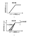
- the design value indicating the relationship between the spool opening (spool position) [mm] and the turning flow rate Q A [L / min] is a linear relationship at the start of the turning operation. And its inclination is constant.
- the crane 1 is operated to simulate various conditions and the relationship between the conventional spool opening (spool position) [mm] and the turning flow rate Q A [L / min] is estimated The result is as shown in FIG. Variations in the spool opening occur with respect to the turning flow rate Q A , and the inclination varies.
- Variation of the inclination is to pivot the load pressure [Delta] P A occurs to change.
- Q p of FIG. 7 (b) shows the variation in the delivery rate of the hydraulic pump 21.
- the maximum value of the turning flow rate Q A (max in FIG. 7B) varies according to the discharge flow rate of the hydraulic pump 21, and the operator 4 intentionally changes the maximum value of the turning flow rate Q A. It is a part resulting from controlling the rotation speed of this, and is not a part corresponding to the subject of this invention.
- the estimated value of the turning load pressure ⁇ P A is calculated in advance, the turning flow rate Q A is estimated from this and the above equation, and the spool for obtaining this turning flow rate Q A is obtained.
- the target value (target position) [mm] of the opening is determined.
- the lever operation amount of the operation lever 20 is uniquely determined from the target value of the opening degree of the spool (see FIG. 5), and based on this, the linearized flow rate characteristic shown in FIG. 6 can be obtained.
- the relationship between the lever operation amount [V] of the operation lever 20 and the turning flow rate Q A [L / min] can be kept linear (constant) at the time of starting the turning operation.
- the control target of the control device 39 which is an example of the swing control device, is not limited to a specific control target, and includes a swing operation unit included in other work machines, mobile vehicles, production machines, and the like that perform the swing operation. .
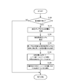
- step S100 the control device 39 determines whether or not the operation lever 20 is operated and the turning operation by the turning motor 7a of the crane 1 is started. That is, the control device 39 determines whether or not an operation signal indicating that the operator has operated the operation lever 20 is input to the calculation unit 39A. As a result, when it is determined that the operation lever 20 is operated and the turning operation by the turning motor 7a is started, the control device 39 shifts the step to step S110. On the other hand, when it is determined that the operation lever 20 is not operated and the turning operation by the turning motor 7a is not performed, the control device 39 shifts the step to step S100.
- step S110 the control device 39 acquires the discharge flow rate Q of the hydraulic pump 21, and shifts the step to step S120.
- step S120 the control unit 39 estimates the turning load pressure [Delta] P A, as described above, it shifts the step to step S130.
- step S130 the control unit 39, the discharge flow rate Q as the above-described arithmetic expression and the turning load pressure [Delta] P A estimated in step S120, the meter diaphragm opening area a in the hydraulic pump 21 acquired in step S110 in the operation section 39A,
- the turning flow rate Q A is estimated by performing calculation processing in the calculation unit 39A using the opening area a out of the meter-out aperture and the opening area a B of the bleed-off aperture, and the process proceeds to step S140.
- step S140 the controller 39 calculates a target value of the spool opening for obtaining a turning flow Q A, linearization table linearizing the relationship between the target value and the lever operation amount of opening of the spool Create Subsequently, the control device 39 shifts the step to step S150.
- step S150 the control unit 39, based on the flow characteristics showing the relationship between the lever operation amount determined based on the linearization table created swirling flow Q A in step S140, the lever operation amount of the operator of the operation lever 20 The turning flow rate Q A corresponding to is uniquely determined. Then, in response to the lever operation amount [V] of the linearized operation lever 20, hydraulic oil is supplied to the turning motor 7a to be controlled, and the turntable 7 is moved to a desired turning angular velocity [deg / s] can be turned (see FIG. 9).
- the control device 39 changes the linearization table that linearizes the relationship between the lever operation amount of the operation lever 20 and the spool target value, lever operation amount of the lever 20 and the relationship of the turning rate Q a is prevented from fluctuation.
- the control device 39 linearizes the relationship between the lever operation amount of the operation lever 20 and the corresponding turning flow rate Q A without changing the valve of the existing hydraulic circuit, and turns.
- the operation can be controlled.
- the turning operation due to changes in discharge flow rate Q and the turning load pressure [Delta] P A of the hydraulic pump 21 e.g., turning angular velocity
- the feedback controllability of the turning operation is improved.
- the present invention can be used as a turning control device that improves the turning operability of a work machine such as a crane.
Abstract
Provided is a revolution control device which achieves revolving operability with little variation in operating feel without depending on the discharge flow rate of a hydraulic pump or a revolving load. This revolution control device 39 controls the revolving movement of a work machine provided with: a revolving stand 7; an operating lever 20 for operating the revolving stand 7; a revolving motor 7a for revolving the revolving stand 7; a hydraulic pump 21 that supplies working oil to the revolving motor 7a; a meter-in circuit; a meter-out circuit; and a bleed off circuit that controls the flow rate of hydraulic oil returning from the hydraulic pump to a tank 50. The revolving load pressure ΔPA applied during the revolution movement of the revolving stand 7 is estimated; the revolving flow rate QA of the working oil flowing into the revolving motor 7a during the revolving movement of the revolving stand 7 is estimated by using a predetermined calculation equation on the basis of the revolving load pressure ΔPA, the discharge flow rate Q of the hydraulic pump 21, the opening area of the meter-in circuit, the opening area of the meter-out circuit, and the opening area of the bleed off circuit; and the relationship between the operation amount of the operating lever 20 and the revolving flow rate QA is linearized.
Description
本発明は、旋回制御装置に関する。詳しくは、クレーン等の作業機械の旋回操作性を向上させる旋回制御装置に関する。
The present invention relates to a turning control device. Specifically, the present invention relates to a turning control device that improves the turning operability of a work machine such as a crane.
従来、クレーンの旋回用油圧回路においては操作性を考慮してブリードオフ回路を採用したものが知られている(特許文献1、2参照)。
Conventionally, crane turning hydraulic circuits that employ a bleed-off circuit in consideration of operability are known (see Patent Documents 1 and 2).
特許文献1では、可変容量油圧ポンプからの圧油を方向制御弁でブリードオフ制御して油圧モータの回転速度を制御する作業機の旋回制御装置が開示されている。この作業機の旋回制御装置は、方向制御弁からタンクへ連通するブリードオフ回路の圧力を油圧モータの駆動圧力と等しく設定し、作業機の作業状態に対して予め対応づけられている方向制御弁の複数の流量特性の中から作業状態に基づいていずれかの流量特性を選択し、その選択された流量特性と操作量に基づいて可変容量油圧ポンプの吐出流量を制御するものである。
Patent Document 1 discloses a swing control device for a working machine that controls the rotational speed of a hydraulic motor by bleed-off control of pressure oil from a variable displacement hydraulic pump with a directional control valve. This swing control device for a work machine sets the pressure of a bleed-off circuit communicating from the direction control valve to the tank equal to the drive pressure of the hydraulic motor, and is a direction control valve previously associated with the working state of the work machine. One of the plurality of flow rate characteristics is selected based on the working state, and the discharge flow rate of the variable displacement hydraulic pump is controlled based on the selected flow rate characteristic and the operation amount.
特許文献2に開示されるアクチュエータのブリードオフ制御装置は、ポンプ吐出量に応じてブリードオフ回路の開閉を行うことで、動作速度を一定に保つというものである。
The bleed-off control device for an actuator disclosed in Patent Document 2 keeps the operating speed constant by opening and closing the bleed-off circuit according to the pump discharge amount.
このようなクレーンの旋回用油圧回路においてブリードオフ回路を採用したものでは、油圧ポンプの吐出流量や旋回時にアクチュエータにかかる負荷(例えば吊荷荷重による負荷)の変動によって、旋回動作の操作レバーのレバー操作量に対して旋回速度が変動する。すなわち、同じような旋回操作をしてもそのときどきに加わる旋回負荷によって動きが変わるという特性を有している。このような旋回操作の特性は、例えば旋回動作をフィードバック制御をしようとしたときに制御性を悪化させたり、操作条件によっては操作品質や操作感覚の悪化を招くという問題点がある。そのため、レバー操作量に対して旋回速度の変動を抑え、旋回速度を条件によらずに安定化させる技術が求められている。すなわち、油圧ポンプの吐出流量や旋回負荷によらず、操作レバーによる旋回操作に対する旋回速度が一定となるような旋回操作性を実現するための技術が求められる。
In such a crane turning hydraulic circuit that employs a bleed-off circuit, the lever of the operation lever for the turning operation depends on fluctuations in the discharge flow rate of the hydraulic pump and the load applied to the actuator during turning (for example, the load due to the suspended load). The turning speed varies with the operation amount. That is, even if the same turning operation is performed, the movement changes depending on the turning load applied at that time. Such characteristics of the turning operation have a problem that, for example, the controllability is deteriorated when feedback control is performed on the turning operation, and the operation quality and the operation feeling are deteriorated depending on the operation conditions. Therefore, there is a demand for a technique that suppresses the fluctuation of the turning speed with respect to the lever operation amount and stabilizes the turning speed regardless of conditions. That is, there is a need for a technique for realizing the turning operability such that the turning speed with respect to the turning operation by the operation lever is constant regardless of the discharge flow rate and the turning load of the hydraulic pump.
本発明は、油圧ポンプの吐出流量や旋回負荷によらず、操作感覚の変動が小さい旋回操作性を実現する旋回制御装置を提供することを目的とする。
An object of the present invention is to provide a turning control device that realizes a turning operability with a small variation in operation feeling irrespective of the discharge flow rate and turning load of a hydraulic pump.
本発明の解決しようとする課題は以上の如くであり、次にこの課題を解決するための手段を説明する。
The problems to be solved by the present invention are as described above. Next, means for solving the problems will be described.
即ち、本発明の旋回制御装置は、旋回台と、前記旋回台を旋回操作するための操作手段と、前記旋回台を旋回するための油圧モータと、前記油圧モータに作動油を供給する油圧ポンプと、前記油圧モータに流入する作動油の流量を制御するメータイン回路と、前記油圧モータから流出する作動油の流量を制御するメータアウト回路と、前記油圧ポンプからタンクに戻る圧油の流量を制御するブリードオフ回路と、を備えた作業機械の旋回動作を制御する旋回制御装置であって、前記旋回台の旋回動作時にかかる旋回負荷圧を推定し、当該旋回負荷圧と前記油圧ポンプの吐出流量と、前記メータイン回路の開口面積と、前記メータアウト回路の開口面積と、前記ブリードオフ回路の開口面積と、から前記旋回台の旋回動作時に前記油圧モータに流入する作動油の旋回流量を所定の演算式により推定し、前記操作手段の操作量と前記旋回流量との関係を線形化するものである。
That is, the turning control device of the present invention includes a turning base, operating means for turning the turning base, a hydraulic motor for turning the turn base, and a hydraulic pump for supplying hydraulic oil to the hydraulic motor. A meter-in circuit for controlling the flow rate of hydraulic oil flowing into the hydraulic motor, a meter-out circuit for controlling the flow rate of hydraulic oil flowing out of the hydraulic motor, and a flow rate of pressure oil returning from the hydraulic pump to the tank And a bleed-off circuit for controlling a turning operation of a work machine, wherein the turning load pressure applied during the turning operation of the swivel base is estimated, and the turning load pressure and the discharge flow rate of the hydraulic pump The opening area of the meter-in circuit, the opening area of the meter-out circuit, and the opening area of the bleed-off circuit. The swirling flow of the hydraulic oil flowing estimated by a predetermined arithmetic expression, is to linearize the relationship between the operation amount and the turning flow of the operating means.
また、前記所定の演算式は、

(式中、Q:油圧ポンプの吐出流量、ΔPA:旋回負荷圧、ain:メータイン回路の開口面積、aout:メータアウト回路の開口面積、aB:ブリードオフ回路の開口面積、R:係数とする)であるものである。
Further, the predetermined arithmetic expression is
(Where, Q: discharge flow rate of hydraulic pump, ΔP A : swing load pressure, a in : opening area of meter-in circuit, a out : opening area of meter-out circuit, a B : opening area of bleed-off circuit, R: Coefficient).
本発明は、以下に示すような効果を奏する。
The present invention has the following effects.
本発明の旋回制御装置においては、既存の油圧回路のバルブ等を変更することなく、操作手段の操作量と、これに対応する旋回流量の関係を線形化して旋回動作を制御することができる。これにより、油圧ポンプの吐出流量や旋回負荷圧の変化による旋回動作(例えば、旋回角速度)の変動を抑制できる。また、例えば、旋回動作(例えば、旋回角速度)がフィードバック制御されている場合では、フィードバック制御性が向上する。さらに、油圧ポンプの吐出流量や旋回負荷圧の変化による旋回動作の操作品質や操作感覚の悪化を抑制することができる。
In the turning control device of the present invention, it is possible to control the turning operation by linearizing the relationship between the operation amount of the operating means and the corresponding turning flow rate without changing the valve or the like of the existing hydraulic circuit. Thereby, the fluctuation | variation of turning operation | movement (for example, turning angular velocity) by the change of the discharge flow rate of a hydraulic pump or turning load pressure can be suppressed. Further, for example, when the turning operation (for example, turning angular velocity) is feedback-controlled, the feedback controllability is improved. Furthermore, it is possible to suppress deterioration of the operation quality and operation feeling of the turning operation due to changes in the discharge flow rate and the turning load pressure of the hydraulic pump.
以下に、図1から図9を用いて、本発明の旋回制御装置の一実施形態である制御装置39を備えるクレーン1について説明する。なお、本実施形態においては、作業機械の一例であるクレーンとして移動式クレーンについて説明を行うが、これに限定されるものではなく、作業時に旋回可能なクレーンであればどのような形態のクレーンにも本発明を適用
することができる。 Below, thecrane 1 provided with the control apparatus 39 which is one Embodiment of the turning control apparatus of this invention is demonstrated using FIGS. 1-9. In this embodiment, a mobile crane will be described as a crane that is an example of a work machine. However, the present invention is not limited to this. The present invention can also be applied.
することができる。 Below, the
図1に示すように、クレーン1は、不特定の場所に移動可能な移動式クレーンである。クレーン1は、車両2、クレーン装置6を有する。
As shown in FIG. 1, the crane 1 is a mobile crane that can move to an unspecified location. The crane 1 has a vehicle 2 and a crane device 6.
車両2は、クレーン装置6を搬送するものである。車両2は、複数の車輪3を有し、エンジン4(図2参照)を動力源として走行する。車両2には、アウトリガ5が設けられている。アウトリガ5は、車両2の幅方向両側に油圧によって延伸可能な張り出しビームと地面に垂直な方向に延伸可能な油圧式のジャッキシリンダとから構成されている。車両2は、アウトリガ5のビームを車両2の幅方向に延伸させるとともにジャッキシリンダを接地させることにより、クレーン1の作業可能範囲を広げることができる。
The vehicle 2 conveys the crane device 6. The vehicle 2 has a plurality of wheels 3 and travels using an engine 4 (see FIG. 2) as a power source. The vehicle 2 is provided with an outrigger 5. The outrigger 5 includes a projecting beam that can be extended by hydraulic pressure on both sides in the width direction of the vehicle 2 and a hydraulic jack cylinder that can extend in a direction perpendicular to the ground. The vehicle 2 can extend the workable range of the crane 1 by extending the beam of the outrigger 5 in the width direction of the vehicle 2 and grounding the jack cylinder.
クレーン装置6は、搬送物Wをワイヤロープによって吊り上げるものである。クレーン装置6は、旋回台7、伸縮ブーム8、フックブロック10、起伏シリンダ12、ウインチ13、ワイヤロープ14、キャビン19、操作レバー20、制御装置39(図4参照)等を具備する。
The crane apparatus 6 lifts the conveyed product W with a wire rope. The crane device 6 includes a swivel base 7, a telescopic boom 8, a hook block 10, a hoisting cylinder 12, a winch 13, a wire rope 14, a cabin 19, an operation lever 20, a control device 39 (see FIG. 4), and the like.
旋回台7は、クレーン装置6を旋回可能に構成するものである。旋回台7は、車体2に設けた円環状の軸受である旋回ベアリングを介して車両2のフレーム上に設けられる。円環状の旋回ベアリングは、その回転中心が車両2の設置面に対して垂直になるように配置されている。旋回台7は、円環状の旋回ベアリングの中心を回転中心として一方向と他方向とに回転自在に構成されている。また、旋回台7は、油圧式モータである旋回モータ7a(図2参照)によって回転(旋回)されるように構成されている。旋回台7には、その旋回位置(旋回角度)を検出する旋回位置検出センサ40(図2参照)が設けられている。旋回位置検出センサ40は、旋回台7の旋回角度を検出するセンサであり、制御装置39では、旋回位置検出センサ40により入力される電気信号に基づいて、旋回台7の旋回角度に係る情報、及び、旋回台7の単位時間当たりの旋回角度を算出することで旋回速度(旋回角速度)に係る情報が得られる。旋回台7の旋回ベアリングには、旋回ベアリングにかかる荷重を検出する旋回ベアリング荷重検出手段43(図4参照)と、旋回ベアリングの車体2に対する傾斜角度を検出する旋回ベアリング傾斜角度検出手段44(図4参照)が設けられている。
The swivel base 7 is configured to allow the crane device 6 to turn. The swivel base 7 is provided on the frame of the vehicle 2 via a swivel bearing that is an annular bearing provided in the vehicle body 2. The ring-shaped slewing bearing is arranged so that the center of rotation is perpendicular to the installation surface of the vehicle 2. The swivel base 7 is configured to be rotatable in one direction and the other direction with the center of the annular swivel bearing as the center of rotation. The swivel base 7 is configured to be rotated (turned) by a swivel motor 7a (see FIG. 2) that is a hydraulic motor. The swivel base 7 is provided with a swivel position detection sensor 40 (see FIG. 2) for detecting the swivel position (turning angle). The turning position detection sensor 40 is a sensor that detects the turning angle of the turntable 7. In the control device 39, information related to the turning angle of the turntable 7 based on the electrical signal input by the turning position detection sensor 40, And the information which concerns on turning speed (turning angular speed) is obtained by calculating the turning angle per unit time of the turntable 7. FIG. The slewing bearing of the slewing base 7 includes a slewing bearing load detecting means 43 (see FIG. 4) for detecting a load applied to the slewing bearing and a slewing bearing inclination angle detecting means 44 (see FIG. 4) for detecting an inclination angle of the slewing bearing with respect to the vehicle body 2. 4).
伸縮ブーム8は、搬送物Wを吊り上げ可能な状態にワイヤロープを支持するものである。伸縮ブーム8は、複数のブーム部材であるベースブーム部材8a、セカンドブーム部材8b、サードブーム部材8c、フォースブーム部材8d、フィフスブーム部材8e、トップブーム部材8fから構成されている。各ブーム部材は、断面積の大きさの順に入れ子式に挿入されている。伸縮ブーム8は、各ブーム部材を図示しない伸縮シリンダで移動させることで軸方向に伸縮自在に構成されている。伸縮ブーム8は、ベースブーム部材8aの基端が旋回台7上に揺動可能に設けられている。これにより、伸縮ブーム8は、車両2のフレーム上で水平回転可能かつ揺動自在に構成されている。伸縮ブーム8には、その伸縮ブーム長さを検出する伸縮ブーム長さ検出センサ41と起伏角度を検出する起伏角度検出センサ42(図4参照)とが設けられている。
The telescopic boom 8 supports the wire rope so that the transported object W can be lifted. The telescopic boom 8 includes a base boom member 8a, a second boom member 8b, a third boom member 8c, a force boom member 8d, a fifth boom member 8e, and a top boom member 8f, which are a plurality of boom members. Each boom member is inserted in a nested manner in the order of the cross-sectional area. The telescopic boom 8 is configured to be telescopic in the axial direction by moving each boom member with an unillustrated telescopic cylinder. The telescopic boom 8 is provided so that the base end of the base boom member 8 a can swing on the swivel base 7. Accordingly, the telescopic boom 8 is configured to be horizontally rotatable and swingable on the frame of the vehicle 2. The telescopic boom 8 is provided with an telescopic boom length detection sensor 41 for detecting the telescopic boom length and a hoisting angle detection sensor 42 (see FIG. 4) for detecting the hoisting angle.
フックブロック10は、搬送物Wを吊るものである。フックブロック10には、ワイヤロープ14が巻き掛けられる複数のフックシーブと、搬送物Wを吊るフックとが設けられている。
The hook block 10 is used to suspend the conveyed product W. The hook block 10 is provided with a plurality of hook sheaves around which the wire rope 14 is wound and a hook for hanging the conveyed product W.
起伏シリンダ12は、伸縮ブーム8を起立および倒伏させ、伸縮ブーム8の姿勢を保持するものである。起伏シリンダ12はシリンダ部とロッド部とからなる油圧シリンダから構成されている。起伏シリンダ12は、シリンダ部の端部が旋回台7に揺動自在に連結され、ロッド部の端部が伸縮ブーム8のベースブーム部材8aに揺動自在に連結されている。起伏シリンダ12は、ロッド部がシリンダ部から押し出されるように作動油が供給されることでベースブーム部材8aを起立させ、ロッド部がシリンダ部に押し戻されるように作動油が供給されることでベースブーム部材8aを倒伏させるように構成されている。起伏シリンダ12には、圧力センサ30(図4参照)が設けられている。吊荷の実荷重は、起伏シリンダ12の圧力センサ30によって検出されるシリンダ圧力と伸縮ブーム8の起伏角度検出センサ42によって検出される起伏角度及び、伸縮ブーム長さ検出センサ41によって検出される伸縮ブーム8の長さとに基づいて制御装置39の図示しない実荷重演算部が演算して求めることができる。また、吊荷を吊っていない場合、予め吊荷の荷重が分かっているときには、図示しない操作部のキー操作によって入力してもよく、仮想の荷重を入力してもよい。
The raising / lowering cylinder 12 raises and lowers the telescopic boom 8 to hold the posture of the telescopic boom 8. The hoisting cylinder 12 is composed of a hydraulic cylinder composed of a cylinder part and a rod part. In the hoisting cylinder 12, the end of the cylinder portion is swingably connected to the swivel base 7, and the end of the rod portion is swingably connected to the base boom member 8 a of the telescopic boom 8. The hoisting cylinder 12 elevates the base boom member 8a by supplying hydraulic oil so that the rod portion is pushed out of the cylinder portion, and the hydraulic oil is supplied so that the rod portion is pushed back to the cylinder portion. The boom member 8a is configured to fall down. The undulating cylinder 12 is provided with a pressure sensor 30 (see FIG. 4). The actual load of the suspended load is the cylinder pressure detected by the pressure sensor 30 of the hoisting cylinder 12, the hoisting angle detected by the hoisting angle detection sensor 42 of the telescopic boom 8, and the expansion / contraction detected by the telescopic boom length detection sensor 41. Based on the length of the boom 8, an actual load calculation unit (not shown) of the control device 39 can calculate and obtain it. Further, when the suspended load is not suspended and the load of the suspended load is known in advance, it may be input by a key operation of an operation unit (not shown) or a virtual load may be input.
油圧ウインチであるウインチ13は、ワイヤロープ14の繰り入れ(巻き上げ)および繰り出し(巻き下げ)を行うものである。ウインチ13は、ワイヤロープ14が巻きつけられるドラムがドラム用油圧モータによって回転されるように構成されている。ウインチ13は、ドラム用油圧モータが一方向へ回転するように作動油が供給されることでドラムに巻きつけられているワイヤロープ14を繰り出し、ドラム用油圧モータが他方向へ回転するように作動油が供給されることでワイヤロープ14をドラムに巻きつけて繰り入れるように構成されている。
A winch 13 that is a hydraulic winch is for feeding (winding up) and feeding (winding down) the wire rope 14. The winch 13 is configured such that a drum around which the wire rope 14 is wound is rotated by a drum hydraulic motor. The winch 13 is supplied with hydraulic oil so that the drum hydraulic motor rotates in one direction, so that the wire rope 14 wound around the drum is fed, and the drum hydraulic motor rotates in the other direction. By supplying oil, the wire rope 14 is wound around a drum and fed.
伸縮ブーム8の伸縮動作に用いられる伸縮シリンダ、起伏動作に用いられる起伏シリンダ12、旋回台7の旋回動作に用いられる旋回モータ7aは、作動油の供給又は排出によって作動する。
The telescoping cylinder used for the telescopic operation of the telescopic boom 8, the hoisting cylinder 12 used for the hoisting operation, and the turning motor 7a used for the turning operation of the swivel base 7 operate by supplying or discharging hydraulic oil.
ワイヤロープ14は、一端がフックブロック10から延伸され、複数のガイドシーブに案内されて、他端が旋回台7に配置されたウインチ13に巻回されている。
One end of the wire rope 14 is extended from the hook block 10, guided by a plurality of guide sheaves, and the other end is wound around a winch 13 disposed on the swivel base 7.
キャビン19は、操縦席を覆うものである。キャビン19は、旋回台7における伸縮ブーム8の側方に設けられ、旋回台7とともに旋回可能である。キャビン19の内部には、操縦席が設けられている。操縦席には、操作レバー20、ウインチ13を操作するためのウインチ用操作弁、伸縮ブーム8を操作するための起伏用操作具、クレーン1を移動させるためのハンドル等が設けられている。
The cabin 19 covers the cockpit. The cabin 19 is provided to the side of the telescopic boom 8 in the swivel base 7 and can swivel together with the swivel base 7. A cockpit is provided inside the cabin 19. The cockpit is provided with an operation lever 20, a winch operation valve for operating the winch 13, a hoisting operation tool for operating the telescopic boom 8, a handle for moving the crane 1, and the like.
操作レバー20は、旋回台7を旋回操作するための操作手段である。操作レバー20は、制御装置39に電気的に接続され、オペレータが操作レバー20を所定角度傾倒することで、これに応じた旋回操作にかかる操作信号を制御装置39に送信することができる。
なお、操作手段としては、操作レバー以外に、押ボタン、ペダル及びタッチパネル等を採用してもよい。 Theoperation lever 20 is an operation means for turning the turntable 7. The operation lever 20 is electrically connected to the control device 39, and the operator can transmit an operation signal for a turning operation corresponding to the operation lever 20 to the control device 39 by tilting the operation lever 20 by a predetermined angle.
In addition to the operation lever, a push button, a pedal, a touch panel, or the like may be employed as the operation means.
なお、操作手段としては、操作レバー以外に、押ボタン、ペダル及びタッチパネル等を採用してもよい。 The
In addition to the operation lever, a push button, a pedal, a touch panel, or the like may be employed as the operation means.
このように構成されるクレーン1は、車両2を走行させることで任意の位置にクレーン装置6を移動させることができる。また、クレーン1は、旋回モータ7aで旋回台7を所定角度回転させるとともに、起伏シリンダ12で伸縮ブーム8を任意の起伏角度に起立させて、伸縮ブーム8を任意の伸縮ブーム長さに延伸させたりすることができる。
The crane 1 configured as described above can move the crane device 6 to an arbitrary position by running the vehicle 2. Further, the crane 1 rotates the swivel base 7 by a predetermined angle by the swing motor 7a, and erects the telescopic boom 8 to an arbitrary hoisting angle by the hoisting cylinder 12 to extend the telescopic boom 8 to an arbitrary telescopic boom length. Can be.
以下に、図2、図3を用いて、クレーン1が具備する旋回モータ7aに関する油圧回路について説明する。
Hereinafter, a hydraulic circuit related to the swing motor 7a included in the crane 1 will be described with reference to FIGS.
油圧回路は、エンジン4からの駆動力が伝導されている油圧ポンプ21、旋回用油圧回路23、および制御装置39を具備する。
The hydraulic circuit includes a hydraulic pump 21 to which driving force from the engine 4 is transmitted, a turning hydraulic circuit 23, and a control device 39.
図2に示すように、油圧ポンプ21は、作動油を吐出するものである。油圧ポンプ21は、エンジン4によって駆動されている。油圧ポンプ21から吐出された作動油は、吐出油路22を介して旋回用油圧回路23、旋回モータ7aに供給される。油圧ポンプ21の吐出油路22には、リリーフ弁22aが設けられている。
As shown in FIG. 2, the hydraulic pump 21 discharges hydraulic oil. The hydraulic pump 21 is driven by the engine 4. The hydraulic oil discharged from the hydraulic pump 21 is supplied to the turning hydraulic circuit 23 and the turning motor 7a through the discharge oil passage 22. A relief valve 22 a is provided in the discharge oil passage 22 of the hydraulic pump 21.
また、旋回用油圧回路23は、図3に示すように流量制御弁から構成される、メータイン回路であるメータイン絞り23a、メータアウト回路であるメータアウト絞り23b、ブリードオフ回路であるブリードオフ絞り23cを有している。メータイン絞り23aは、旋回モータ7aの作動油供給側に配置され、旋回モータ7aに流入する作動油の流量を制御するものである。メータアウト絞り23bは、旋回モータ7aの作動油排出側に配置され、旋回モータ7aから流出する作動油の流量を制御するものである。ブリードオフ絞り23cは、油圧ポンプ21からタンク50に戻る圧油の流量を制御するものである。ブリードオフ絞り23cは、図示せぬスプールの開度を調整することで流量を制御することができる。
Further, as shown in FIG. 3, the turning hydraulic circuit 23 includes a meter-in throttle 23a that is a meter-in circuit, a meter-out throttle 23b that is a meter-out circuit, and a bleed-off throttle 23c that is a bleed-off circuit. have. The meter-in throttle 23a is disposed on the hydraulic oil supply side of the swing motor 7a and controls the flow rate of the hydraulic oil flowing into the swing motor 7a. The meter-out throttle 23b is disposed on the hydraulic oil discharge side of the swing motor 7a and controls the flow rate of the hydraulic oil flowing out of the swing motor 7a. The bleed-off throttle 23c controls the flow rate of the pressure oil that returns from the hydraulic pump 21 to the tank 50. The bleed-off throttle 23c can control the flow rate by adjusting the opening of a spool (not shown).
図2に示すように、旋回用油圧回路23は、旋回モータ7aを作動させるものである。旋回用油圧回路23は、旋回モータ7a、旋回用操作弁24、旋回用パイロット式切換弁25、旋回位置検出センサ40を備える。
As shown in FIG. 2, the turning hydraulic circuit 23 operates the turning motor 7a. The turning hydraulic circuit 23 includes a turning motor 7 a, a turning operation valve 24, a turning pilot-type switching valve 25, and a turning position detection sensor 40.
旋回モータ7aは、旋回台7を回転させるものである。旋回モータ7aは、旋回台7と連動連結するように構成されている。旋回モータ7aは、作動油が供給されると旋回台7一側方向または他側方向に回転させる。
The turning motor 7a rotates the turntable 7. The turning motor 7 a is configured to be interlocked with the turning table 7. When the hydraulic oil is supplied, the turning motor 7a rotates in the one side direction or the other side direction of the turning table 7.
旋回用操作弁24は、旋回モータ7aの動作を制御するものである。旋回用操作弁24は、旋回用パイロット式切換弁25に付加されるパイロット圧を電磁石でスプールを移動させることで切り換え可能な電磁切換弁から構成されている。また、旋回用操作弁24は、制御装置39からの制御信号によって電磁石を励起可能に構成されている。旋回用操作弁24には、油圧ポンプ21からパイロット圧が供給されている。旋回用操作弁24は、制御装置39を介して操作レバー20による操作信号により制御される。
The turning operation valve 24 controls the operation of the turning motor 7a. The turning operation valve 24 is composed of an electromagnetic switching valve that can switch the pilot pressure applied to the turning pilot type switching valve 25 by moving the spool with an electromagnet. Further, the turning operation valve 24 is configured to excite the electromagnet by a control signal from the control device 39. Pilot pressure is supplied from the hydraulic pump 21 to the turning operation valve 24. The turning operation valve 24 is controlled by an operation signal from the operation lever 20 via the control device 39.
旋回用操作弁24は、制御装置39から操作信号を受けていない場合、スプールが停止位置Sに保持される。旋回用操作弁24は、制御装置39から旋回台7を一側に回転させる操作信号を受けた場合、電磁石によってスプールが一側旋回位置Rに移動される。旋回用操作弁24は、制御装置39から旋回台7を他側に回転させる操作信号を受けた場合、電磁石によってスプールが他側旋回位置Lに移動される。
When the operation valve 24 for turning is not receiving an operation signal from the control device 39, the spool is held at the stop position S. When the operation valve for turning 24 receives an operation signal for rotating the turntable 7 to one side from the control device 39, the spool is moved to the one-side turning position R by the electromagnet. When the turning operation valve 24 receives an operation signal for rotating the swivel base 7 from the control device 39 to the other side, the spool is moved to the other side turning position L by the electromagnet.
旋回用パイロット式切換弁25は、旋回モータ7aに供給される作動油の方向を切り換えるものである。旋回用パイロット式切換弁25の供給ポートには、吐出油路22を介して油圧ポンプ21が接続されている。旋回用パイロット式切換弁25の一方のポートには、一側旋回用油路26を介して旋回モータ7aの一側が接続されている。旋回用パイロット式切換弁25の他方のポートには他側旋回用油路27を介して旋回モータ7aの他側が接続されている。
The turning pilot type switching valve 25 switches the direction of the hydraulic oil supplied to the turning motor 7a. A hydraulic pump 21 is connected to a supply port of the turning pilot type switching valve 25 via a discharge oil passage 22. One side of the turning pilot type switching valve 25 is connected to one side of a turning motor 7 a via a one-side turning oil passage 26. The other port of the turning pilot type switching valve 25 is connected to the other side of the turning motor 7 a via the other-side turning oil passage 27.
旋回用パイロット式切換弁25は、旋回用操作弁24のスプールが停止位置Sに保持されている場合、一側旋回用油路26と他側旋回用油路27とを閉鎖する。これにより、旋回モータ7aは、その回転位置が保持される。旋回用パイロット式切換弁25は、旋回用操作弁24のスプールが一側旋回位置Rに移動された場合、油圧ポンプ21からの作動油が一側旋回用油路26を介して旋回モータ7aの一側に供給されるように切り換る。これにより、旋回モータ7aは、旋回台7を一側方向に回転させる方向に作動される。旋回用パイロット式切換弁25は、旋回用操作弁24のスプールが他側旋回位置Lに移動された場合、油圧ポンプ21からの作動油が他側旋回用油路27を介して旋回モータ7aの他側に供給されるように切り換る。これにより、旋回モータ7aは、旋回台7を他側方向に回転させる方向に作動される。
The turning pilot type switching valve 25 closes the one-side turning oil passage 26 and the other-side turning oil passage 27 when the spool of the turning operation valve 24 is held at the stop position S. Thereby, the rotation position of the turning motor 7a is maintained. When the spool of the turning operation valve 24 is moved to the one-side turning position R, the turning pilot-type switching valve 25 allows the hydraulic oil from the hydraulic pump 21 to move to the turning motor 7a via the one-side turning oil passage 26. Switch to supply to one side. Thereby, the turning motor 7a is operated in a direction in which the turntable 7 is rotated in one direction. When the spool of the turning operation valve 24 is moved to the other side turning position L, the working oil from the hydraulic pump 21 is supplied to the turning pilot type switching valve 25 via the other side turning oil passage 27. Switch to supply to the other side. Thereby, the turning motor 7a is actuated in a direction for rotating the turntable 7 in the other direction.
このように構成される旋回用油圧回路23を備えるクレーン1は、制御装置39からの操作信号に基づいて旋回用操作弁24を操作することで旋回用パイロット式切換弁25を切り換える。つまり、クレーン1は、制御装置39からの操作信号によって旋回モータ7aに供給される作動油の流れを切り換えて旋回台7の旋回動作を自在に行うことができる。
The crane 1 having the turning hydraulic circuit 23 configured as described above switches the turning pilot type switching valve 25 by operating the turning operation valve 24 based on the operation signal from the control device 39. That is, the crane 1 can freely turn the swivel base 7 by switching the flow of hydraulic oil supplied to the turning motor 7 a according to an operation signal from the control device 39.
制御装置39は、クレーン1が有するアクチュエータ等の動作を制御する装置である。具体的には、制御装置39は、制御形態の一例として、クレーン1が有するアクチュエータの一つである旋回モータ7aによる旋回動作を制御するための旋回制御装置である。制御装置39は、実体的には、CPU、ROM、RAM、HDD等がバスで接続される構成であってもよく、あるいはワンチップのLSI等からなる構成であってもよい。制御装置39は、旋回用操作弁24等の動作を制御するために種々のプログラムやデータが格納されている。制御装置39は、車両2に設けられている。制御装置39は、各種センサ等から種々の電気信号が入力され、適宜の演算処理が可能であり、油圧ポンプ21及び各種流量制御弁等に対してそれぞれ駆動信号を出力することができる。制御装置39は、あらかじめ記憶部に記憶した演算式、各種センサ等から取得される検出値等を用いて種々の演算を実行する演算部39Aを有している。また、制御装置39は、旋回台7の旋回動作の制御を一般的なフィードバック制御で行うための制御装置である。
The control device 39 is a device that controls the operation of an actuator or the like that the crane 1 has. Specifically, the control device 39 is a turning control device for controlling a turning operation by the turning motor 7a which is one of actuators included in the crane 1 as an example of a control form. The control device 39 may actually be configured such that a CPU, ROM, RAM, HDD, or the like is connected by a bus, or may be configured by a one-chip LSI or the like. The control device 39 stores various programs and data for controlling the operation of the turning operation valve 24 and the like. The control device 39 is provided in the vehicle 2. The control device 39 receives various electrical signals from various sensors and can perform appropriate arithmetic processing, and can output drive signals to the hydraulic pump 21 and various flow control valves, respectively. The control device 39 includes a calculation unit 39A that executes various calculations using calculation formulas stored in advance in a storage unit, detection values acquired from various sensors, and the like. Further, the control device 39 is a control device for controlling the turning operation of the turntable 7 by general feedback control.
図4に示すように、制御装置39は、起伏シリンダ12の圧力センサ30に接続されている。吊荷(本実施形態の搬送物W)の実荷重は、例えば、起伏シリンダ12の圧力センサ30によって検出されるシリンダ圧力と伸縮ブーム8の起伏角度検出センサ42によって検出される起伏角度及び、伸縮ブーム長さ検出センサ41によって検出される伸縮ブーム8の長さとに基づいて制御装置39の図示しない実荷重演算部が演算して求めることができる。
As shown in FIG. 4, the control device 39 is connected to the pressure sensor 30 of the hoisting cylinder 12. The actual load of the suspended load (conveyed object W of the present embodiment) includes, for example, the cylinder pressure detected by the pressure sensor 30 of the hoisting cylinder 12, the hoisting angle detected by the hoisting angle detection sensor 42 of the telescopic boom 8, and the expansion and contraction. Based on the length of the telescopic boom 8 detected by the boom length detection sensor 41, an actual load calculation unit (not shown) of the control device 39 can calculate and obtain it.
制御装置39は、旋回台7の旋回位置検出センサ40に接続され、旋回位置検出センサ40が検出した旋回台7の旋回方向および旋回角度を取得することができる。
The control device 39 is connected to the turning position detection sensor 40 of the turntable 7, and can acquire the turning direction and the turning angle of the turntable 7 detected by the turning position detection sensor 40.
制御装置39は、伸縮ブーム8の伸縮ブーム長さ検出センサ41と起伏角度検出センサ42とに接続され、伸縮ブーム長さ検出センサ41が検出した伸縮ブーム8の伸縮ブーム長さおよび起伏角度検出センサ42が検出した伸縮ブーム8の起伏角度を取得することができる。
The control device 39 is connected to the telescopic boom length detection sensor 41 and the hoisting angle detection sensor 42 of the telescopic boom 8, and the telescopic boom length and hoisting angle detection sensor of the telescopic boom 8 detected by the telescopic boom length detection sensor 41. The undulation angle of the telescopic boom 8 detected by 42 can be acquired.
制御装置39は、車体2に設けた旋回ベアリング荷重検出手段43に接続され、旋回ベアリングにかかる荷重を取得することができる。旋回ベアリング荷重検出手段43の例としては、圧力センサ等が挙げられる。
The control device 39 is connected to the slewing bearing load detecting means 43 provided on the vehicle body 2 and can acquire the load applied to the slewing bearing. An example of the slewing bearing load detection means 43 includes a pressure sensor.
制御装置39は、旋回ベアリング傾斜角度検出手段44に接続され、車体2に設けた旋回ベアリングの車体2に対する傾斜角度を取得することができる。
The control device 39 is connected to the slewing bearing tilt angle detecting means 44 and can acquire the tilt angle of the slewing bearing provided on the vehicle body 2 with respect to the vehicle body 2.
次に、制御装置39による旋回モータ7aの制御態様について説明する。
本実施形態の制御装置39は、旋回台7の旋回動作時にかかる旋回負荷圧ΔPAを推定し、当該旋回負荷圧ΔPAと油圧ポンプ21の吐出流量Qと、メータイン回路の開口面積と、メータアウト回路の開口面積と、ブリードオフ回路の開口面積と、から旋回台7の旋回動作時に旋回モータ7aに流入する作動油の旋回流量QAを所定の演算式を用いて推定し、操作レバー20のレバー操作量と旋回流量QAとの関係を線形化する。詳細を以下に説明する。 Next, a control mode of the turningmotor 7a by the control device 39 will be described.
Control device 39 of the present embodiment estimates the turning load pressure [Delta] P A according to the time of turning operation of the turning base 7, and the discharge flow rate Q of the turning load pressure [Delta] P A and the hydraulic pump 21, and the opening area of the meter-circuit, the meter Based on the opening area of the out circuit and the opening area of the bleed-off circuit, the swirling flow rate Q A of the hydraulic oil flowing into the swiveling motor 7a during the swiveling operation of the swivel base 7 is estimated using a predetermined arithmetic expression, and the control lever 20 The relationship between the lever operation amount and the turning flow rate Q A is linearized. Details will be described below.
本実施形態の制御装置39は、旋回台7の旋回動作時にかかる旋回負荷圧ΔPAを推定し、当該旋回負荷圧ΔPAと油圧ポンプ21の吐出流量Qと、メータイン回路の開口面積と、メータアウト回路の開口面積と、ブリードオフ回路の開口面積と、から旋回台7の旋回動作時に旋回モータ7aに流入する作動油の旋回流量QAを所定の演算式を用いて推定し、操作レバー20のレバー操作量と旋回流量QAとの関係を線形化する。詳細を以下に説明する。 Next, a control mode of the turning
[旋回負荷圧ΔPAの推定]
本実施形態では、制御装置39は、油圧ポンプ21の吐出流量Qや旋回台7の旋回動作時に掛かる圧力(旋回負荷圧)による旋回角速度の変動を抑制するために、油圧ポンプ21の吐出流量Qと旋回負荷圧ΔPAに応じて、操作レバー20のレバー操作量とブリードオフ絞り23cのバルブ開度(以下では単にスプール開度ともいう)の関係を示すテーブルを変化させる(後述する線形化テーブルの生成)。制御装置39は、荷重情報として車体2に設けた旋回ベアリングにかかる荷重、姿勢情報として旋回ベアリングの傾斜角度及びクレーンの作業姿勢、操作情報としてオペレータの操作入力の情報、エンジン情報としてエンジン4の回転数の情報、その他の機差による負荷変動量等の旋回負荷圧ΔPAにかかる情報、その他定数(旋回ベアリング諸元(摩擦係数など)、旋回動作の減速比(≒総等価容量)、総効率)等を適宜取得して、この情報をもとに旋回負荷圧ΔPAを推定する。推定する旋回負荷圧ΔPAは、クレーンの姿勢や荷重によって変化する負荷である。ただし、荷の振れや伸縮ブーム8の慣性による旋回負荷圧ΔPAの変動は考慮していない。
なお、旋回負荷圧ΔPAは、旋回台7の旋回動作の起動時に旋回モータ7aにかかるトルクに相当する。 [Estimation of the turning load pressure [Delta] P A]
In the present embodiment, thecontrol device 39 controls the discharge flow rate Q of the hydraulic pump 21 and the discharge flow rate Q of the hydraulic pump 21 in order to suppress fluctuations in the turning angular velocity due to the pressure applied during the turning operation of the turntable 7 (swing load pressure). and in accordance with the turning load pressure [Delta] P a, linearization table (simply referred to as spool opening degree below) to alter the table showing the relationship (described later lever operation amount of the operation lever 20 and the bleed-off aperture 23c of valve opening Generation). The control device 39 loads the load applied to the slewing bearing provided on the vehicle body 2 as load information, the tilting angle of the slewing bearing and the crane working posture as posture information, the operation input information of the operator as operation information, and the rotation of the engine 4 as engine information. the number of information, other instrumental error due to the load variation such as turning load pressure ΔP information according to a of the other such constants (swing bearing specifications (coefficient of friction), the reduction ratio of the turning operation (≒ total equivalent capacitance), the total efficiency ), or the like as appropriate get to the estimates the turning load pressure [Delta] P a based on this information. Turning load pressure [Delta] P A of estimating is a load which varies depending on the posture and the load of the crane. However, the variation of the turning load pressure [Delta] P A due to the inertia of the load deflection and telescopic boom 8 is not taken into consideration.
Incidentally, the turning load pressure [Delta] P A corresponds to a torque applied to theswing motor 7a at the start of turning operation of the swivel base 7.
本実施形態では、制御装置39は、油圧ポンプ21の吐出流量Qや旋回台7の旋回動作時に掛かる圧力(旋回負荷圧)による旋回角速度の変動を抑制するために、油圧ポンプ21の吐出流量Qと旋回負荷圧ΔPAに応じて、操作レバー20のレバー操作量とブリードオフ絞り23cのバルブ開度(以下では単にスプール開度ともいう)の関係を示すテーブルを変化させる(後述する線形化テーブルの生成)。制御装置39は、荷重情報として車体2に設けた旋回ベアリングにかかる荷重、姿勢情報として旋回ベアリングの傾斜角度及びクレーンの作業姿勢、操作情報としてオペレータの操作入力の情報、エンジン情報としてエンジン4の回転数の情報、その他の機差による負荷変動量等の旋回負荷圧ΔPAにかかる情報、その他定数(旋回ベアリング諸元(摩擦係数など)、旋回動作の減速比(≒総等価容量)、総効率)等を適宜取得して、この情報をもとに旋回負荷圧ΔPAを推定する。推定する旋回負荷圧ΔPAは、クレーンの姿勢や荷重によって変化する負荷である。ただし、荷の振れや伸縮ブーム8の慣性による旋回負荷圧ΔPAの変動は考慮していない。
なお、旋回負荷圧ΔPAは、旋回台7の旋回動作の起動時に旋回モータ7aにかかるトルクに相当する。 [Estimation of the turning load pressure [Delta] P A]
In the present embodiment, the
Incidentally, the turning load pressure [Delta] P A corresponds to a torque applied to the
制御装置39は、旋回ベアリングにかかる荷重を検出する旋回ベアリング荷重検出手段43と、旋回ベアリングの車両2に対する傾斜角度を検出する旋回ベアリング傾斜角度検出手段44に接続されている。制御装置39は、旋回ベアリング荷重検出手段43及び旋回ベアリング傾斜角度検出手段44を介して旋回ベアリングにかかる荷重及び旋回ベアリングの車両2に対する傾斜角度を取得することができる。また、制御装置39は、クレーン1の作業姿勢を検出する手段として、例えば、圧力センサ30、旋回位置検出センサ40、伸縮ブーム長さ検出センサ41、起伏角度検出センサ42等を用いてクレーン1の作業姿勢を検出することができる。
なお、旋回負荷圧ΔPAは、主に搬送物Wの吊荷荷重による旋回ベアリングにかかるモーメントによって決定される。そのため、旋回負荷圧ΔPAは、少なくとも旋回ベアリング荷重検出手段43で取得される旋回ベアリングにかかる荷重を用いて推定が可能である。 Thecontrol device 39 is connected to a slewing bearing load detection unit 43 that detects a load applied to the slewing bearing and a slewing bearing tilt angle detection unit 44 that detects an inclination angle of the slewing bearing with respect to the vehicle 2. The control device 39 can obtain the load applied to the slewing bearing and the tilt angle of the slewing bearing with respect to the vehicle 2 via the slewing bearing load detection unit 43 and the slewing bearing tilt angle detection unit 44. Further, the control device 39 uses, for example, the pressure sensor 30, the turning position detection sensor 40, the telescopic boom length detection sensor 41, the undulation angle detection sensor 42, etc. as means for detecting the working posture of the crane 1. The working posture can be detected.
Incidentally, the turning load pressure [Delta] P A is mainly determined by the moment applied to the swing bearing by suspended load load of the conveyed W. Therefore, the turning load pressure [Delta] P A is capable of estimating with a load applied to the swing bearing, which is acquired by at least swing bearingload detecting means 43.
なお、旋回負荷圧ΔPAは、主に搬送物Wの吊荷荷重による旋回ベアリングにかかるモーメントによって決定される。そのため、旋回負荷圧ΔPAは、少なくとも旋回ベアリング荷重検出手段43で取得される旋回ベアリングにかかる荷重を用いて推定が可能である。 The
Incidentally, the turning load pressure [Delta] P A is mainly determined by the moment applied to the swing bearing by suspended load load of the conveyed W. Therefore, the turning load pressure [Delta] P A is capable of estimating with a load applied to the swing bearing, which is acquired by at least swing bearing
[旋回流量QAの推定]
次に、上述した旋回負荷圧ΔPAと油圧ポンプ21の吐出流量Qと下記式を用いて旋回流量QAを推定する。旋回流量QAは、クレーン1の旋回動作時に旋回モータ7aに供給される作動油の流量であり、本発明では旋回動作前にレバー操作量[V]と旋回流量QA[L/min]との関係を示す線形化された流動特性(図6参照)を導くために算出される値である。以下に、旋回流量QAを導出する演算式を示す。 [Estimation of swirling flow rate Q A ]
Next, estimate the turning flow Q A with the discharge flow rate Q and the following formula of the turning load pressure [Delta] P A and thehydraulic pump 21 described above. The turning flow rate Q A is a flow rate of hydraulic oil supplied to the turning motor 7a during the turning operation of the crane 1. In the present invention, the lever operation amount [V] and the turning flow rate Q A [L / min] Is a value calculated to derive a linearized flow characteristic (see FIG. 6) showing the relationship of An arithmetic expression for deriving the turning flow rate Q A is shown below.
次に、上述した旋回負荷圧ΔPAと油圧ポンプ21の吐出流量Qと下記式を用いて旋回流量QAを推定する。旋回流量QAは、クレーン1の旋回動作時に旋回モータ7aに供給される作動油の流量であり、本発明では旋回動作前にレバー操作量[V]と旋回流量QA[L/min]との関係を示す線形化された流動特性(図6参照)を導くために算出される値である。以下に、旋回流量QAを導出する演算式を示す。 [Estimation of swirling flow rate Q A ]
Next, estimate the turning flow Q A with the discharge flow rate Q and the following formula of the turning load pressure [Delta] P A and the

ここで、式中のΔPAは、上述した旋回モータ7aの旋回動作時の旋回負荷圧の推定値である。
また、油圧ポンプ21の吐出流量Qは、制御装置39によりエンジン4の回転数から算出される。
また、メータイン絞り23aの開口面積ain、メータアウト絞り23bの開口面積aout、及びブリードオフ絞り23cの開口面積aBは、スプールの開度(スプールの位置)によって一意に決まるものである。
Here, [Delta] P A in the formula is an estimate of the turning operation when turning load pressure of the
Further, the discharge flow rate Q of the
Also, the meter opening area a in the
制御装置39は、油圧ポンプ21、メータイン絞り23a、メータアウト絞り23b及びブリードオフ絞り23cに接続され、油圧ポンプ21の吐出流量Q、メータイン絞り23aの開口面積ain、メータアウト絞り23bの開口面積aout、及びブリードオフ絞り23cの開口面積aBをそれぞれ取得することができる。
The control device 39 is connected to the hydraulic pump 21, the meter-in throttle 23a, the meter-out throttle 23b, and the bleed-off throttle 23c, and the discharge flow rate Q of the hydraulic pump 21, the opening area a in of the meter- in throttle 23a, and the opening area of the meter-out throttle 23b. a out and the opening area a B of the bleed-off stop 23c can be acquired.
[線形化テーブルの生成]
上記のように旋回流量QAが推定することができれば、この旋回流量QAを得るためのスプールの開度が一意的に設定することできるため、旋回負荷圧ΔPAによる旋回角速度の変動による傾斜ばらつきが統一され、線形化された線形化テーブルを得ることができる(図5参照)。
すなわち、図10に示すように、設計値と上記演算式によって求まるカーブの関係から旋回流量QAの設計値となるレバー操作量に応じたスプールの開度の目標値(スプールの目標位置P)を算出することができる。
なお、図5に示す点線丸印部分は、意図的に設けられた不感帯飛ばし部分である。 [Generate linearization table]
If the turning flow rate Q A can be estimated as described above, the opening degree of the spool for obtaining the turning flow rate Q A can be set uniquely, so that the inclination due to the change in the turning angular velocity due to the turning load pressure ΔP A It is possible to obtain a linearized table in which variations are unified and linearized (see FIG. 5).
That is, as shown in FIG. 10, the spool opening target value (spool target position P) corresponding to the lever operation amount, which is the design value of the turning flow rate Q A , from the relationship between the design value and the curve obtained from the above arithmetic expression. Can be calculated.
In addition, the dotted line circle mark part shown in FIG. 5 is a dead zone skip part provided intentionally.
[線形化後の流動特性]
図5に示す線形化テーブルにより、旋回流量QAと操作レバー20のレバー操作量が一意的に決定され、レバー操作量[V]と旋回流量QA[L/min]との関係を示す線形化後の流動特性(図6参照)を得ることができる。本実施形態に係る流動特性は、後述する図7(b)に示す従来の流動特性と比べて線形の関係を保持している。 [Flow characteristics after linearization]
The linearization table shown in FIG. 5 uniquely determines the turning flow rate Q A and the lever operation amount of theoperation lever 20, and shows the relationship between the lever operation amount [V] and the turning flow rate Q A [L / min]. The flow characteristics after conversion (see FIG. 6) can be obtained. The flow characteristics according to the present embodiment maintain a linear relationship as compared with the conventional flow characteristics shown in FIG.
図5に示す線形化テーブルにより、旋回流量QAと操作レバー20のレバー操作量が一意的に決定され、レバー操作量[V]と旋回流量QA[L/min]との関係を示す線形化後の流動特性(図6参照)を得ることができる。本実施形態に係る流動特性は、後述する図7(b)に示す従来の流動特性と比べて線形の関係を保持している。 [Flow characteristics after linearization]
The linearization table shown in FIG. 5 uniquely determines the turning flow rate Q A and the lever operation amount of the
図7(a)に示すように、スプールの開度(スプールの位置)[mm]と旋回流量QA[L/min]との関係を示す設計値は、旋回動作の起動時において線形の関係であり、その傾きは一定である。この傾き部分については旋回流量QAとスプールの開度(スプールの位置)とは一意的な関係となる。しかし、クレーン1を稼働して諸条件を振ったシミュレーションを実施して、従来のスプールの開度(スプールの位置)[mm]と旋回流量QA[L/min]との関係を推定した場合、図7(b)に示すような結果となる。旋回流量QAに対してスプール開度のばらつきが発生し、傾きが変動する。この傾きの変動は、旋回負荷圧ΔPAが変動するために発生するものである。なお、図7(b)のQpは油圧ポンプ21の吐出流量の変動を示したものである。また、油圧ポンプ21の吐出流量に応じて旋回流量QAの最大値(図7(b)のmax)は変動するが、この旋回流量QAの最大値の変動はオペレータが意図的にエンジン4の回転数を制御することに起因する部分であり、本発明の課題に対応する部分ではない。本発明では、旋回操作の起動開始時において、あらかじめ旋回負荷圧ΔPAの推定値を算出し、これと上記演算式により旋回流量QAを推定し、この旋回流量QAを得るためのスプールの開度の目標値(目標位置)[mm]を決定する。これにより、スプールの開度の目標値から操作レバー20のレバー操作量が一意的に決定され(図5参照)、これに基づいて図6に示す線形化後の流量特性を得ることができる。この線形化後の流量特性では、旋回操作の起動時において操作レバー20のレバー操作量[V]と旋回流量QA[L/min]の関係を線形(一定)に保つことができる。
As shown in FIG. 7A, the design value indicating the relationship between the spool opening (spool position) [mm] and the turning flow rate Q A [L / min] is a linear relationship at the start of the turning operation. And its inclination is constant. A unique relationship with the opening of the swirl flow Q A and the spool (the position of the spool) for the inclination part. However, when the crane 1 is operated to simulate various conditions and the relationship between the conventional spool opening (spool position) [mm] and the turning flow rate Q A [L / min] is estimated The result is as shown in FIG. Variations in the spool opening occur with respect to the turning flow rate Q A , and the inclination varies. Variation of the inclination is to pivot the load pressure [Delta] P A occurs to change. Incidentally, Q p of FIG. 7 (b) shows the variation in the delivery rate of the hydraulic pump 21. The maximum value of the turning flow rate Q A (max in FIG. 7B) varies according to the discharge flow rate of the hydraulic pump 21, and the operator 4 intentionally changes the maximum value of the turning flow rate Q A. It is a part resulting from controlling the rotation speed of this, and is not a part corresponding to the subject of this invention. In the present invention, at the start of turning operation, the estimated value of the turning load pressure ΔP A is calculated in advance, the turning flow rate Q A is estimated from this and the above equation, and the spool for obtaining this turning flow rate Q A is obtained. The target value (target position) [mm] of the opening is determined. Thereby, the lever operation amount of the operation lever 20 is uniquely determined from the target value of the opening degree of the spool (see FIG. 5), and based on this, the linearized flow rate characteristic shown in FIG. 6 can be obtained. With this flow characteristic after linearization, the relationship between the lever operation amount [V] of the operation lever 20 and the turning flow rate Q A [L / min] can be kept linear (constant) at the time of starting the turning operation.
旋回制御装置の一例である制御装置39の制御対象は、特定の制御対象に限定するものでなく、旋回動作を実施するその他の作業機械、移動車両、生産機械等が有する旋回動作部が含まれる。
The control target of the control device 39, which is an example of the swing control device, is not limited to a specific control target, and includes a swing operation unit included in other work machines, mobile vehicles, production machines, and the like that perform the swing operation. .
次に、図8を用いて、クレーン1の制御装置39にによる旋回モータ7aの制御フローについて具体的に説明する。
Next, the control flow of the turning motor 7a by the control device 39 of the crane 1 will be specifically described with reference to FIG.
ステップS100において、制御装置39は、操作レバー20が操作され、クレーン1の旋回モータ7aによる旋回動作が開始されるか否か判断する。すなわち、制御装置39は、演算部39Aにオペレータが操作レバー20を操作した操作信号が入力されたか否か判断する。
その結果、操作レバー20が操作され、旋回モータ7aによる旋回動作が開始されたと判定された場合、制御装置39はステップをステップS110に移行させる。
一方、操作レバー20が操作されず、旋回モータ7aによる旋回動作が実施されていないと判定された場合、制御装置39はステップをステップS100に移行させる。 In step S100, thecontrol device 39 determines whether or not the operation lever 20 is operated and the turning operation by the turning motor 7a of the crane 1 is started. That is, the control device 39 determines whether or not an operation signal indicating that the operator has operated the operation lever 20 is input to the calculation unit 39A.
As a result, when it is determined that theoperation lever 20 is operated and the turning operation by the turning motor 7a is started, the control device 39 shifts the step to step S110.
On the other hand, when it is determined that theoperation lever 20 is not operated and the turning operation by the turning motor 7a is not performed, the control device 39 shifts the step to step S100.
その結果、操作レバー20が操作され、旋回モータ7aによる旋回動作が開始されたと判定された場合、制御装置39はステップをステップS110に移行させる。
一方、操作レバー20が操作されず、旋回モータ7aによる旋回動作が実施されていないと判定された場合、制御装置39はステップをステップS100に移行させる。 In step S100, the
As a result, when it is determined that the
On the other hand, when it is determined that the
ステップS110において、制御装置39は、油圧ポンプ21の吐出流量Qを取得し、ステップをステップS120に移行させる。
In step S110, the control device 39 acquires the discharge flow rate Q of the hydraulic pump 21, and shifts the step to step S120.
ステップS120において、制御装置39は、上述したように旋回負荷圧ΔPAを推定し、ステップをステップS130に移行させる。
In step S120, the control unit 39 estimates the turning load pressure [Delta] P A, as described above, it shifts the step to step S130.
ステップS130において、制御装置39は、演算部39AにおいてステップS110で取得した油圧ポンプ21の吐出流量QとステップS120で推定した旋回負荷圧ΔPAと上述した演算式、メータイン絞りの開口面積ain、メータアウト絞りの開口面積aout、ブリードオフ絞りの開口面積aBを用いて演算部39Aで演算処理することで旋回流量QAを推定し、ステップをステップS140に移行させる。
In step S130, the control unit 39, the discharge flow rate Q as the above-described arithmetic expression and the turning load pressure [Delta] P A estimated in step S120, the meter diaphragm opening area a in the hydraulic pump 21 acquired in step S110 in the operation section 39A, The turning flow rate Q A is estimated by performing calculation processing in the calculation unit 39A using the opening area a out of the meter-out aperture and the opening area a B of the bleed-off aperture, and the process proceeds to step S140.
ステップS140において、制御装置39は、旋回流量QAを得るためのスプールの開度の目標値を算出し、当該スプールの開度の目標値とレバー操作量との関係を線形化した線形化テーブルを作成する。続いて、制御装置39は、ステップをステップS150に移行させる。
In step S140, the controller 39 calculates a target value of the spool opening for obtaining a turning flow Q A, linearization table linearizing the relationship between the target value and the lever operation amount of opening of the spool Create Subsequently, the control device 39 shifts the step to step S150.
ステップS150において、制御装置39は、ステップS140で作成した線形化テーブルに基づいて決定されるレバー操作量と旋回流量QAの関係を示す流動特性に基づいて、オペレータの操作レバー20のレバー操作量に対応する旋回流量QAが一意的に決定される。そして、線形化後の操作レバー20のレバー操作量[V]に対応して、制御対象である旋回モータ7aに対して作動油の供給が実行され、旋回台7を所望の旋回角速度[deg/s]で旋回操作することができる(図9参照)。
以上のように、オペレータが操作レバー20により旋回動作を行うごとに、制御装置39は、操作レバー20のレバー操作量とスプールの目標値の関係を線形化した線形化テーブルを変更して、操作レバー20のレバー操作量と旋回流量QAの関係が変動しないようにしている。 In step S150, thecontrol unit 39, based on the flow characteristics showing the relationship between the lever operation amount determined based on the linearization table created swirling flow Q A in step S140, the lever operation amount of the operator of the operation lever 20 The turning flow rate Q A corresponding to is uniquely determined. Then, in response to the lever operation amount [V] of the linearized operation lever 20, hydraulic oil is supplied to the turning motor 7a to be controlled, and the turntable 7 is moved to a desired turning angular velocity [deg / s] can be turned (see FIG. 9).
As described above, every time the operator performs a turning motion with theoperation lever 20, the control device 39 changes the linearization table that linearizes the relationship between the lever operation amount of the operation lever 20 and the spool target value, lever operation amount of the lever 20 and the relationship of the turning rate Q a is prevented from fluctuation.
以上のように、オペレータが操作レバー20により旋回動作を行うごとに、制御装置39は、操作レバー20のレバー操作量とスプールの目標値の関係を線形化した線形化テーブルを変更して、操作レバー20のレバー操作量と旋回流量QAの関係が変動しないようにしている。 In step S150, the
As described above, every time the operator performs a turning motion with the
以上のように構成することで、制御装置39では、既存の油圧回路のバルブを変更することなく、操作レバー20のレバー操作量と、これに対応する旋回流量QAの関係を線形化して旋回動作を制御することができる。これにより、油圧ポンプ21の吐出流量Qや旋回負荷圧ΔPAの変化による旋回動作(例えば、旋回角速度)の変動を抑制できる。また、例えば、旋回動作(例えば、旋回角速度)がフィードバック制御されている場合、旋回動作のフィードバック制御性が向上する。さらに、油圧ポンプ21の吐出流量Qや旋回負荷圧ΔPAの変化による旋回動作の操作品質や操作感覚の悪化を抑制することができる。すなわち、油圧ポンプ21の吐出流量Qや旋回負荷圧ΔPAによらず、操作レバー20による旋回操作に対する旋回速度が一定となるような旋回操作性を実現することができる。
With the configuration as described above, the control device 39 linearizes the relationship between the lever operation amount of the operation lever 20 and the corresponding turning flow rate Q A without changing the valve of the existing hydraulic circuit, and turns. The operation can be controlled. Thereby, the turning operation due to changes in discharge flow rate Q and the turning load pressure [Delta] P A of the hydraulic pump 21 (e.g., turning angular velocity) can suppress the variation of. Further, for example, when the turning operation (for example, the turning angular velocity) is feedback-controlled, the feedback controllability of the turning operation is improved. Furthermore, it is possible to suppress the deterioration of the operation quality and operation feeling of the turning operation due to changes in discharge flow rate Q and the turning load pressure [Delta] P A of the hydraulic pump 21. That is, regardless of the discharge flow rate Q and the turning load pressure [Delta] P A of the hydraulic pump 21 can be rotation speed for the turning operation by the operation lever 20 to realize the turning operation of such a constant.
上述の実施形態は、代表的な形態を示したに過ぎず、一実施形態の骨子を逸脱しない範囲で種々変形して実施することができる。さらに種々なる形態で実施し得ることは勿論のことであり、本発明の範囲は、特許請求の範囲の記載によって示され、さらに特許請求の範囲に記載の均等の意味、および範囲内のすべての変更を含む。
The above-described embodiment merely shows a representative form, and various modifications can be made without departing from the essence of the embodiment. It goes without saying that the present invention can be embodied in various forms, and the scope of the present invention is indicated by the description of the scope of claims, and the equivalent meanings of the scope of claims, and all the scopes within the scope of the claims Includes changes.
本発明は、クレーン等の作業機械の旋回操作性を向上させる旋回制御装置として利用可能である。
The present invention can be used as a turning control device that improves the turning operability of a work machine such as a crane.
1 クレーン(作業機械)
7 旋回台
7a 旋回モータ(油圧モータ)
20 操作レバー(操作手段)
21 油圧ポンプ
23a メータイン絞り(メータイン回路)
23b メータアウト絞り(メータアウト回路)
23c ブリードオフ絞り(ブリードオフ回路)
39 制御装置(旋回制御装置)
50 タンク
ΔPA 旋回負荷圧
Q 油圧ポンプの吐出流量
QA 旋回流量 1 Crane (work machine)
7swivel base 7a swivel motor (hydraulic motor)
20 Operation lever (operation means)
21Hydraulic pump 23a Meter-in throttle (meter-in circuit)
23b Meter-out aperture (meter-out circuit)
23c Bleed-off stop (bleed-off circuit)
39 Control device (turning control device)
50 Tank ΔP A Swing load pressure Q Hydraulic pump discharge flow Q A Swing flow
7 旋回台
7a 旋回モータ(油圧モータ)
20 操作レバー(操作手段)
21 油圧ポンプ
23a メータイン絞り(メータイン回路)
23b メータアウト絞り(メータアウト回路)
23c ブリードオフ絞り(ブリードオフ回路)
39 制御装置(旋回制御装置)
50 タンク
ΔPA 旋回負荷圧
Q 油圧ポンプの吐出流量
QA 旋回流量 1 Crane (work machine)
7
20 Operation lever (operation means)
21
23b Meter-out aperture (meter-out circuit)
23c Bleed-off stop (bleed-off circuit)
39 Control device (turning control device)
50 Tank ΔP A Swing load pressure Q Hydraulic pump discharge flow Q A Swing flow
Claims (2)
- 旋回台と、
前記旋回台を旋回操作するための操作手段と、
前記旋回台を旋回するための油圧モータと、
前記油圧モータに作動油を供給する油圧ポンプと、
前記油圧モータに流入する作動油の流量を制御するメータイン回路と、
前記油圧モータから流出する作動油の流量を制御するメータアウト回路と、
前記油圧ポンプからタンクに戻る圧油の流量を制御するブリードオフ回路と、を備えた作業機械の旋回動作を制御する旋回制御装置であって、
前記旋回台の旋回動作時にかかる旋回負荷圧を推定し、当該旋回負荷圧と前記油圧ポンプの吐出流量と、前記メータイン回路の開口面積と、前記メータアウト回路の開口面積と、前記ブリードオフ回路の開口面積と、から前記旋回台の旋回動作時に前記油圧モータに流入する作動油の旋回流量を所定の演算式により推定し、
前記操作手段の操作量と前記旋回流量との関係を線形化する旋回制御装置。 Swivel,
Operation means for turning the turntable;
A hydraulic motor for turning the swivel;
A hydraulic pump for supplying hydraulic oil to the hydraulic motor;
A meter-in circuit for controlling the flow rate of hydraulic oil flowing into the hydraulic motor;
A meter-out circuit for controlling the flow rate of hydraulic oil flowing out from the hydraulic motor;
A slewing control device for controlling a slewing operation of a work machine including a bleed-off circuit for controlling a flow rate of pressure oil returning from the hydraulic pump to the tank,
The swivel load pressure applied during the swivel operation of the swivel is estimated, the swivel load pressure, the discharge flow rate of the hydraulic pump, the opening area of the meter-in circuit, the opening area of the meter-out circuit, and the bleed-off circuit From the opening area, the swirling flow rate of the hydraulic oil flowing into the hydraulic motor during the swiveling operation of the swivel base is estimated by a predetermined arithmetic expression,
A turning control device for linearizing a relationship between an operation amount of the operating means and the turning flow rate. - 前記所定の演算式は、

Applications Claiming Priority (2)
| Application Number | Priority Date | Filing Date | Title |
|---|---|---|---|
| JP2017013711A JP6540724B2 (en) | 2017-01-27 | 2017-01-27 | Turning control device |
| JP2017-013711 | 2017-01-27 |
Publications (1)
| Publication Number | Publication Date |
|---|---|
| WO2018139166A1 true WO2018139166A1 (en) | 2018-08-02 |
Family
ID=62978310
Family Applications (1)
| Application Number | Title | Priority Date | Filing Date |
|---|---|---|---|
| PCT/JP2017/047294 WO2018139166A1 (en) | 2017-01-27 | 2017-12-28 | Revolution control device |
Country Status (2)
| Country | Link |
|---|---|
| JP (1) | JP6540724B2 (en) |
| WO (1) | WO2018139166A1 (en) |
Families Citing this family (1)
| Publication number | Priority date | Publication date | Assignee | Title |
|---|---|---|---|---|
| JP7184672B2 (en) * | 2019-02-27 | 2022-12-06 | 株式会社タダノ | work vehicle |
Citations (6)
| Publication number | Priority date | Publication date | Assignee | Title |
|---|---|---|---|---|
| JPH0610905A (en) * | 1992-06-24 | 1994-01-21 | Komatsu Ltd | Opening control method for operation valve |
| JPH10159809A (en) * | 1996-11-28 | 1998-06-16 | Kobe Steel Ltd | Flow controller for hydraulic actuator |
| JPH1136376A (en) * | 1997-07-17 | 1999-02-09 | Komatsu Ltd | Swing starting-controlling device in work machine |
| JPH1171097A (en) * | 1997-09-01 | 1999-03-16 | Hitachi Constr Mach Co Ltd | Turn control device for work machine |
| JP2000009102A (en) * | 1998-06-22 | 2000-01-11 | Kobe Steel Ltd | Hydraulic actuator control device |
| JP2015067993A (en) * | 2013-09-27 | 2015-04-13 | ダイキン工業株式会社 | Construction machine |
Family Cites Families (2)
| Publication number | Priority date | Publication date | Assignee | Title |
|---|---|---|---|---|
| JPH0258062U (en) * | 1988-10-17 | 1990-04-26 | ||
| JP4997138B2 (en) * | 2008-02-20 | 2012-08-08 | 日立建機株式会社 | Load machine |
-
2017
- 2017-01-27 JP JP2017013711A patent/JP6540724B2/en active Active
- 2017-12-28 WO PCT/JP2017/047294 patent/WO2018139166A1/en active Application Filing
Patent Citations (6)
| Publication number | Priority date | Publication date | Assignee | Title |
|---|---|---|---|---|
| JPH0610905A (en) * | 1992-06-24 | 1994-01-21 | Komatsu Ltd | Opening control method for operation valve |
| JPH10159809A (en) * | 1996-11-28 | 1998-06-16 | Kobe Steel Ltd | Flow controller for hydraulic actuator |
| JPH1136376A (en) * | 1997-07-17 | 1999-02-09 | Komatsu Ltd | Swing starting-controlling device in work machine |
| JPH1171097A (en) * | 1997-09-01 | 1999-03-16 | Hitachi Constr Mach Co Ltd | Turn control device for work machine |
| JP2000009102A (en) * | 1998-06-22 | 2000-01-11 | Kobe Steel Ltd | Hydraulic actuator control device |
| JP2015067993A (en) * | 2013-09-27 | 2015-04-13 | ダイキン工業株式会社 | Construction machine |
Also Published As
| Publication number | Publication date |
|---|---|
| JP2018119667A (en) | 2018-08-02 |
| JP6540724B2 (en) | 2019-07-10 |
Similar Documents
| Publication | Publication Date | Title |
|---|---|---|
| JPWO2017115809A1 (en) | Excavator | |
| WO2009104449A1 (en) | Interference prevention control device for operating machinery | |
| JP5719440B2 (en) | Flow control device for variable displacement hydraulic pump for construction machinery | |
| KR20180132039A (en) | Shovel | |
| US20170184139A1 (en) | Method of controlling velocity of a hydraulic actuator in over-center linkage systems | |
| US7546729B2 (en) | Method and system for limiting torque load associated with an implement | |
| WO2020049668A1 (en) | Hydraulic drive device of electric-powered hydraulic operating machine | |
| JP2010230039A (en) | Hydraulic circuit | |
| JP5970625B1 (en) | Construction machine, hybrid hydraulic excavator, and motor generator output torque control method | |
| JP6803194B2 (en) | Hydraulic drive system for construction machinery | |
| WO2018139166A1 (en) | Revolution control device | |
| CN108883915B (en) | Crane with a movable crane | |
| CN113454346B (en) | work vehicle | |
| WO2016121185A1 (en) | Rotation control device | |
| JP5639855B2 (en) | Hydraulic drive device and work machine equipped with hydraulic drive device | |
| JP2001302183A (en) | Hydraulic speed controller, hook overwinding prevention device, and interference prevention device | |
| JP6943798B2 (en) | Excavator | |
| CN109689982B (en) | Construction machine | |
| JP6445352B2 (en) | Work machine | |
| JP4490654B2 (en) | Accelerator control device for work equipment | |
| JP2018184299A (en) | Revolving drive device and work machine with the same | |
| JP2001199676A (en) | Hydraulic circuit for operation system of construction machine | |
| WO2022210776A1 (en) | Excavator | |
| JP3538311B2 (en) | Hydraulic control device for construction machinery | |
| JP2021021199A (en) | Shovel |
Legal Events
| Date | Code | Title | Description |
|---|---|---|---|
| 121 | Ep: the epo has been informed by wipo that ep was designated in this application |
Ref document number: 17894059 Country of ref document: EP Kind code of ref document: A1 |
|
| NENP | Non-entry into the national phase |
Ref country code: DE |
|
| 122 | Ep: pct application non-entry in european phase |
Ref document number: 17894059 Country of ref document: EP Kind code of ref document: A1 |